U1411 Jeep Code: Quick Fixes For Fuel Volume Signal Issues
U1411 Jeep Code: Quick Fixes For Fuel Volume Signal Issues
Welcome to our expert guide on the U1411 Jeep code. If you’ve encountered this code during a diagnostic scan, don’t fret!
As a seasoned mechanic with years of experience working on Jeeps, I’m here to provide valuable insights and help you confidently resolve the issue.
In this comprehensive article, we will delve into the meaning, severity, symptoms, causes, and diagnosis of the U1411 code. I’ll share my expertise and insider knowledge to empower you to get your Jeep back on the road in no time.
So let’s unlock the secrets behind the U1411 code. Your Jeep’s optimal performance awaits!
U1411 Jeep: A Quick Overview
Below is a summary of the U1411 Jeep Code. Check it out!
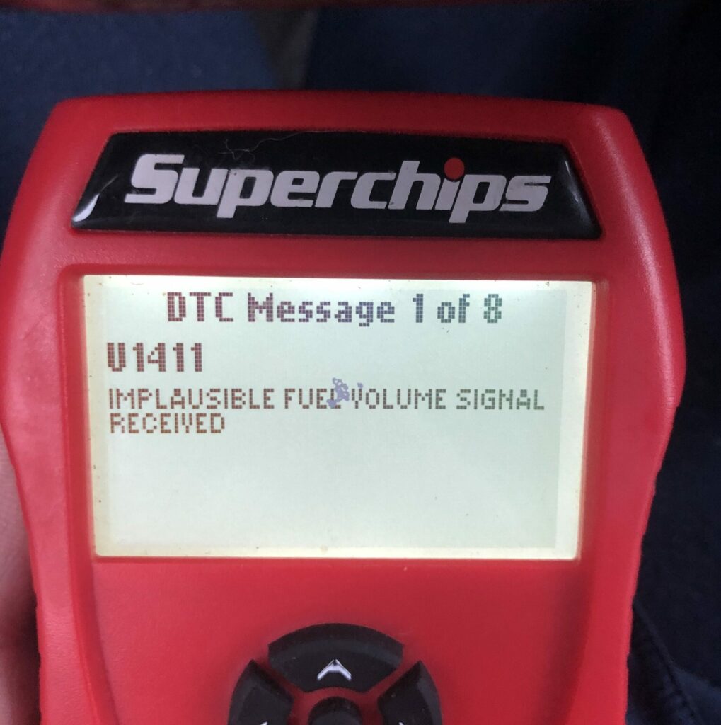
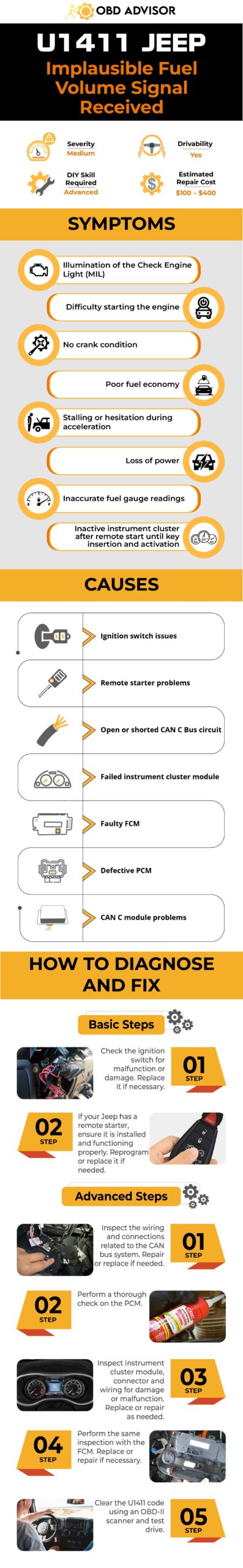
- Definition: Implausible Fuel Volume Signal Received
- Severity: Medium
- DIY Skill Level: Advanced
- Continue To Drive?: Yes
- Estimated Repair Cost: $100 – $400
Understanding The U1411 Code In Jeeps
The U1411 code in Jeeps is an OBD-II diagnostic trouble code that indicates an “Implausible Fuel Volume Signal Received.” When this code appears during a scan, it means that the Powertrain Control Module (PCM) has detected an inconsistent or unreliable fuel volume signal.
Several systems and components work together in your Jeep to ensure proper fuel volume measurement and delivery. The main players involved are:
- PCM
- Front Control Module (FCM)
- Fuel Pump Control Module (FPCM)
- Fuel Level Sensor
- Fuel Rail Pressure Sensor
- The Controller Area Network (CAN) bus
(Image credit: Jeep Garage – Jeep Forum)
When the FCM in your Jeep fails to receive a fuel volume signal from the Cluster Module over the CAN B bus, it sends a fuel volume signal to the PCM over the CAN C bus. However, if the PCM determines that the signal sent by the FCM over CAN C is implausible or inconsistent, it will result in the U1411 code being triggered.
It’s worth noting that the U1411 code is most commonly found in these Jeep models: Jeep Grand Cherokee (2005, 2006), Jeep Liberty (2006), and Jeep Commander. Additionally, it is commonly associated with other codes such as P0157 (Oxygen Sensor Circuit Low Voltage Bank 2 Sensor 2), U110C (Lost Fuel Volume Message), and U110E (Lost Ambient Temperature Message).
Read more: Dodge, Chrysler, and Jeep OBD1 Codes and OBD2 Codes [Full PDF Free Download]
Assessing The Severity: Is It Safe To Drive With The U1411 Jeep Code?
The severity level of the U1411 code in your Jeep can be considered moderate. While this code typically indicates an issue with the fuel volume signal, it is not a critical or immediate danger to your safety.
It is generally safe to drive with this code. However, it is important not to ignore the U1411 code and address it promptly. Ignoring the code may lead to potential fuel delivery problems, affecting your Jeep’s performance and fuel efficiency. It is advisable to have the issue diagnosed and repaired as soon as possible to prevent further complications.
U1411 Jeep Symptoms: How The Code Manifests In Your Jeep
The U1411 code in your Jeep may manifest itself through various symptoms, indicating an issue with the fuel volume signal. Keep an eye out for the following signs:
- Illumination of the Check Engine Light (MIL)
- Difficulty starting the engine
- No crank condition
- Poor fuel economy
- Stalling or hesitation during acceleration
- Loss of power
- Inaccurate fuel gauge readings
- The instrument cluster remains inactive after remote start until the key is inserted and turned on
Read more: Jeep Dashboard Symbols and Meaning (FULL list, Free Download)
Exploring The Causes Of the U1411 Code
To effectively diagnose and resolve the U1411 code in your Jeep, it is important to understand its potential causes. The following are common culprits associated with this code:
- Ignition switch issues
- Remote starter problems
- Open or shorted CAN C Bus circuit
- Failed instrument cluster module
- Faulty FCM
- Defective PCM
- CAN C module problems
Diagnosis And Repair: Resolving The U1411 Code Like A Pro
In this section, we’ll provide you with the tools, parts, step-by-step guide, and estimated costs to resolve the U1411 code in your Jeep. Let’s begin.
Essential Tools And Parts
To diagnose and repair the U1411 code, you may need the following tools and parts:
- OBD-II scanner
- Di-electric cleaner
- Replacement ignition switch (if needed)
- Replacement parts for wiring, connectors, circuits, PCM, Instrument Cluster, and FCM (as required)
Step-by-step Procedure
The procedure is divided into two parts, Basic and Advanced, to ensure a comprehensive and systematic approach to troubleshooting and resolving issues.
Basic Steps
Trying out the following steps in many situations can often resolve the issue.
You can give them a shot in the comfort of your own home before deciding whether to take your car to a repair shop or dealer.
These steps are accessible to those with beginner to intermediate skill and knowledge levels:
Step 1: First, check the ignition switch for malfunction or damage. Replace it if necessary.
Step 2: If your Jeep has a remote starter, ensure it is installed and functioning properly. Reprogram or replace it if needed.
Advanced Steps
If you have completed the basic steps and the U1411 code persists, doing more advanced troubleshooting that involves working with complex wiring and specific components may be necessary.
Please note that these steps require advanced automotive knowledge and skill. It is recommended to seek assistance from a qualified mechanic or automotive professional with the expertise to perform these tasks accurately and safely.
Step 1: Inspect the wiring and connections related to the CAN bus system, including the CAN C Bus circuit. Repair or replace any damaged or faulty wiring, connectors, or circuits.
Step 2: Perform a thorough check on the PCM using the following steps:
- Disconnect all PCM connectors carefully.
- Use a di-electric cleaner to spray and clean all PCM connections.
- Allow the cleaner to sit and dry.
- Clean the exposed large cable behind the fuse box under the hood on the driver’s side. Let it sit overnight alongside the disconnected PCM cables.
- Reconnect the cables and check if the U1411 code is reset. If not, reprogram or replace the PCM module.
Step 3: Inspect the instrument cluster module for damage or malfunction. Ensure it is properly connected and all wiring is in good condition. Replace or repair as needed.
Step 4: Perform the same inspection with the FCM. Replace or repair if necessary.
Step 5: Clear the U1411 code using an OBD-II scanner and test drive the vehicle.
How Much Does It Cost To Fix The U1411 Jeep Code?
The cost of repairing the U1411 code in a Jeep can vary depending on the specific cause and the parts that need replacement. Below is a table showing estimated costs for some common repair tasks related to the U1411 code based on the troubleshooting steps mentioned earlier.
| Repair Task | Estimated Cost Range |
| Wiring and connector inspection/repair | $100 – $500 |
| Ignition switch replacement | $150 – $300 |
| Remote starter repair/reprogram | $100 – $300 |
| Powertrain Control Module (PCM) inspection/repair/replace | $500 – $1,500 |
| Instrument cluster module inspection/repair | $300 – $800 |
| Front Control Module (FCM) inspection/repair | $300 – $800 |
Remember that these estimated costs are subject to variation depending on factors such as labor rates and the Jeep model. Consulting with a qualified mechanic will provide you with a more accurate estimate tailored to your specific situation.
U1411 Jeep Infographic
Final Thoughts
Congratulations! You now have a solid understanding of the U1411 Jeep code, from its meaning to symptoms, causes, and possible repair procedures. Armed with this knowledge, you’re better equipped to tackle this issue should it arise in your vehicle.
Remember, if you’re unsure about performing the diagnosis and repair yourself, it’s always wise to seek the expertise of a professional mechanic. They have the experience and specialized tools to accurately diagnose the problem and ensure a proper fix.
We hope this guide has been helpful to you. If you found it informative, don’t hesitate to share it with fellow Jeep owners who may benefit from this knowledge. Feel free to leave any questions or comments below. Happy driving!
Reference Sources
- Zinref.ru, Jeep Grand Cherokee WK. Manual – part 1130.
- RepairPal, DTC Code U1411.
- JustAnswer, Question about U1411 Code in 2006 Jeep Commander Code.
P1345 Chevy: Crankshaft position- camshaft position correlation
P1345 Chevy: Crankshaft position- camshaft position correlation
Vehicle owners who are not mechanics have a major problem in common – the difficulty of getting rid of certain DTCs. The P1345 code is definitely one of these Diagnostic Trouble Codes.
Worry not. This article will dive deep into the P1345 code on GM (Chevrolet) vehicles. We will tackle an older Chevy engine model, specifically the 5.7 Vortec, in which this problem is highly prominent.
However, this knowledge is transferable and will help you fix your Chevy. There will be a few differences depending on the engine design and the types of ignition triggers. At the very end, you will be able to fix the problem yourself, if you are a little bit handy.
P1345 Chevy definition and meaning
Definition
Trouble code P1345 is a manufacturer-specific code defined as Crankshaft position-camshaft position correlation on General Motors vehicles.
Meaning
P1345 is a manufacturer-specific DTC, which means that diagnosing it will be different for different manufacturers. Moreover, the code may only apply to specific vehicles: Audi, Isuzu, Toyota, BMW, GM (Chevrolet and GMC), Lexus, Mazda, and Volkswagen. The P1345 code on a Chevy or GMC truck will defer from the same code in another car model.
Regardless of the definitions, these codes have one thing in common – they indicate an ignition problem. As earlier stated, these codes defer due to the type of engine and ignition triggers used in each specific vehicle. However, they have another thing in common: the application of Camshaft Position Sensors (CMS) and Crankshaft Position Sensors (CKS).
The camshaft position sensor is a sensor in your vehicle. It provides the Engine Control Module (ECM) or Powertrain control module (PCM) as referred to in some vehicles, with the exact position of the camshaft lobes relative to the valve openings on each cylinder. This information will then be used by the Engine control module (ECM) to choose the best fuel injector timing.
On the other hand, there is the crankshaft position sensor (CKS), which is a sensor that provides a signal to the engine control module indicating the position of the crankshaft or crankshaft timing relative to the top dead center on the compression stroke of the cylinder number 1 in the engine.
These two sensors work together with the engine control module to control engine timing. These sensors will be in sync if everything is working properly. When the interrelation between the camshaft position sensor and crankshaft position sensors is out of sync for more than 1 or 2 degrees, the error code P1345 will be recorded.
The P1345 Chevy code may be caused by faulty CKS and CMS sensors, but in most cases, it results from a problem in engine timing. This confusion is done away with in newer vehicles whose engines adjust the timing themselves. In these newer vehicles, you will also receive a p0335 code and p0340, telling you that the CKS and CMS sensors are bad or malfunctioning.
List of OBD2 codes that relate to P1345 on Chevy
1. P0335 – Crankshaft Position Sensor ‘A’ Circuit malfunction
2. P0340 – Camshaft Position Sensor ‘A’ Circuit malfunction
Symptoms of P1345 on Chevy?
1. Check engine light ‘ON’ – like other codes, this code will trigger the ‘check engine’ light and get stored in the vehicle’s memory system.
2. Engine misfires above 1500 rpm – an engine may misfire if there is a problem with the distributor, resulting in the lack of enough current to ignite the spark plugs. The resulting trouble is a misfire. At higher speeds, the ECM usually tries to adjust valve lift. Therefore, engine misfiring may be an indication of your valve timing being off.
3. Rough idling and stalling while driving – most engine problems such as these will deem your engine performance inefficient, resulting in the engine idling and stalling.
4. Difficulty in starting the engine – an engine with poor timing will exhibit difficulties in starting up since the engine timing is crucial for its operation. Newer vehicles improved on this by having the engine time itself.
Causes of P1345 on Chevy?
1. Loose, faulty, or bad camshaft position sensors and crankshaft position sensors (highly unlikely)
The CKS and CMS may be faulty if the p0335 code and/or p0340 codes are recorded too. A quick fix for this would be to replace the sensors or have a mechanic fix them. However, in the absence of these two codes, the problem will be located elsewhere.
2. Stretched, slipped, or improperly installed valve timing chain
There may be an excessive free play on the valve timing chain and gear assembly that may result in the valve timing being off. This may be due to mechanical wear or improper installation.
3. Incorrect distributor positioning or loose distributor rotor on the distributor shaft (most likely)
The distributor transfers current to the ignition coils for firing up the spark plugs. If it fails, it will not deliver current at the right time to the appropriate coil resulting in misfires and engine timing going off.
4. Bad wiring connections causing simple electrical connection failures
Chafing, corroding, rubbing, or burning spots on melted wire insulation may result in connection problems. These types of wiring problems should be checked as a regular maintenance procedure.
How serious is the P1345 Chevy OBD2 code?
As much as you may get by without fixing this trouble code for a while, it is advisable not to. The engine will have trouble starting on multiple occasions, and it may also suddenly stop. These two scenarios are not any driver’s cup of tea. Moreover, the check engine light may end up staying on till you fix the problem.
How to diagnose and fix the code P1345 on Chevy?
Tools needed
- OBD2 scan tool
- Electrical cleaner
- Plastic bristle brush
- Dielectric silicone grease
- Digital Volt Ohm Meter (DVOM)
Method
We are specifically tackling a 5.7 Vortec engine here. You will need to check if there are any technical service bulletins (TBS) for your vehicle. This may save you time and money if the manufacturer has put out a fix for this specific problem.
1. You will first need an OBD scan tool to connect to the OBD port on your car. Use it to scan for all the stored codes to ensure you diagnose those other codes before the P1345.
2. Check for any corroded, burnt, or defective wiring in the connections around the CKS and CMS sensors. Pull the connectors apart and inspect the terminals inside. If they are corroded or burnt, you will have to clean them with an electrical cleaner and the brush listed above.
Let them dry. Apply dielectric silicone grease on the terminals before returning the sensors.
3. Check for any damages and faults on and around the CKS and CMS sensors. If any, you will need to replace them and see if the problem is solved. To see if the sensors are working correctly, you will need to use a Digital Volt Ohm Meter (DVOM). Test the 5V power supply circuit going to each sensor to ensure it is being powered up.
4. Clear the trouble codes from memory and see if the P1345 code returns. If it does, then the problem is elsewhere. Proceed to the next step.
5. Analyze the assembly of the timing chain and gear assembly to make sure there is no excessive free play. Fix the problem by adjusting the installation. You may also need to get spare parts for the affected components. If this does not fix the problem, then the last and final diagnosis will be a problem with the distributor.
A distributor may be loose or missing. It is responsible for current delivery to ignition coils in the correct firing order and correct time period. It contains a rotor, which may be loose in this case. On top of this, the gear inside of the distributor may be bad.
The distributor may need to be replaced, but if it is new and/or in good working condition, its positioning is probably off.
6. Using the scan tool, connect it to the OBD port on your vehicle with ignition OFF. Start the engine. From the scan tool, read the “Cam Retard Offset,” you will need to get your engine to 1000 rpm for accurate results.
7. A reading of +/-2 degrees of Zero is an indication of optimal timing. Otherwise, you will need to adjust the distributor. You can adjust it by loosening the bolt on the distributor while the engine is off. Connect scan tool and monitor the “Cam Retard Offset” reading. Start the engine and make sure it reaches 1000 rpm.
8. Adjust the positioning by turning the distributor clockwise if the reading is positive and anticlockwise if the reading is negative. Do this till the “Cam Retard Offset” reading is within +/- 2 degrees of Zero, finally solving the issue.
Read more: How can I perform CASE relearn without a scan tool?
Tips to avoid P1345 in the Future
1. Perform regular preventive maintenance. Problems related to P1345 will be caught earlier.
2. Avoid driving through deep puddles because water will get into the distributor cap and short out.
FAQs
How do I know the distributor is not the problem for P1345 ?
If other codes such as p0335 and p0340 are saved, there is a high likelihood the problem lies elsewhere but directly or indirectly affects valve timing and its components.
What is the cost of diagnosing the P1345 Chevy code?
The charges vary depending on where you take your vehicle for repair. The charges average at around $75 to $150 an hour. Diagnosing the P1345 Chevy code will take approximately 1 hour.
What if all the solutions listed above do not fix the problem?
If you carefully follow all the steps above, the problem will be fixed. However, if it persists or other issues such as the engine not starting and misfires, you may have another component issue. Scan for the DTCs and see what the codes are indicating. Proceed from there.
Does this solution apply to the P1345 code in other vehicles apart from GM (Chevrolet and GMC truck)?
This solution is specific to GM and Chevrolet vehicles. Search for Technical Service Bulletins by your manufacturer for a detailed solution to different manufacturers.
What if I have the P1345 code, but the engine works fine?
This is a clear indication that symptoms will surely come after some time. Take your car for maintenance to fix it sooner rather than later.
P1281 Dodge Code: Engine Temperature Troubles
P1281 Dodge Code: Engine Temperature Troubles
Today, we’re tackling a common concern for Dodge owners: the P1281 code.
If you’ve noticed your engine temperature acting up and that pesky check engine light popping up, don’t worry! We’re here to help you make sense of it all.
In this article, we’ll take a close look at the P1281 Dodge code and its connection to your engine’s temperature.
Let’s get started! Say goodbye to engine temperature troubles and hello to a reliable Dodge vehicle!
P1281 Dodge: A Quick Overview
Curious about the P1281 Dodge code? Check out our quick summary for essential details!
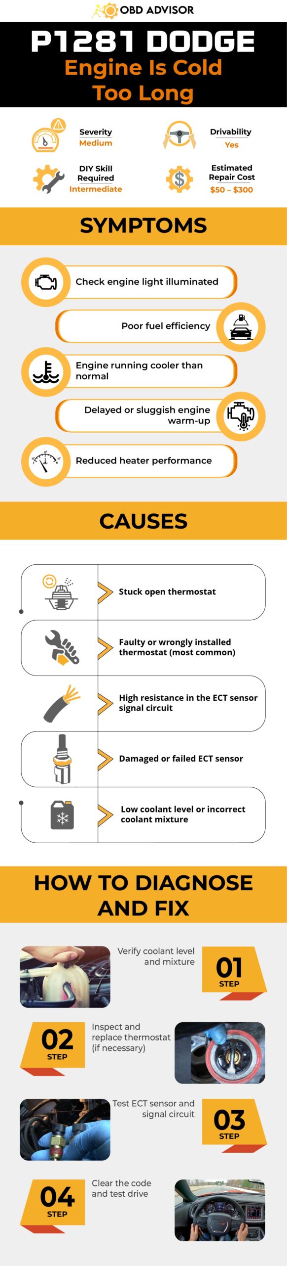
- Definition: Engine Is Cold Too Long
- Severity: Medium
- DIY Skill Level: Intermediate
- Continue To Drive?: Yes
- Estimated Repair Cost: $50 – $300
Understanding P1281 Dodge: What Does The Code Mean?
The P1281 code points to a specific issue related to the engine’s operating temperature. Your Dodge vehicle relies on various interconnected systems and components to regulate and maintain the engine’s temperature. Among these key components are the thermostat, engine coolant temperature (ECT) sensor, and engine control module (ECM). Together, they work harmoniously to ensure the engine operates within the optimal temperature range.
If the engine fails to reach the required temperature within the specified time frame, the ECM detects this anomaly and triggers the P1281 code. Specifically, this code indicates that the engine has not reached a temperature above 176 degrees Fahrenheit (80 degrees Celsius) for more than 20 minutes of continuous driving since it was first started.
It’s worth noting that the P1281 code is commonly found in Dodge models such as the Ram 1500, Dakota, Durango, and Neon. Additionally, it is often associated with other codes like P0443 (Evaporative Emission Control System Purge Control Valve Circuit) and P0420 (Catalyst System Efficiency Below Threshold).
P1281 Dodge: To Drive Or Not To Drive?
When it comes to the severity of the P1281 code, it is considered a moderate-level issue. While it may not pose an immediate danger to your vehicle’s operation, it shouldn’t be ignored. It can impact fuel efficiency, emissions, and overall engine performance.
It is generally safe to continue driving with the P1281 code, especially if you haven’t experienced any noticeable symptoms or performance issues. However, we recommend that you diagnose and repair the issue at your earliest convenience to prevent potential long-term complications and ensure the optimal performance of your vehicle.
Common Symptoms Of P1281 Dodge
Typical symptoms associated with this code include:
- Check Engine Light (MIL) illuminated
- Poor fuel efficiency
- Engine running cooler than normal
- Delayed or sluggish engine warm-up
- Reduced heater performance
Read more: Dodge RAM Warning Light Symbols and Meaning (FULL list, FREE Download)
What Triggers P1281 Dodge?
The P1281 code can be triggered by several underlying causes, which may include:
- Stuck open thermostat
- Faulty or wrongly installed thermostat (most common)
- High resistance in the ECT sensor signal circuit
- Damaged or failed ECT sensor
- Low coolant level or incorrect coolant mixture
Diagnosing And Repairing P1281 Dodge: A Step-by-Step Guide
This section will provide you with a step-by-step guide to diagnose and repair the P1281 code. Before we begin, let’s take a look at the essential tools and parts you may need for the procedure:
Essential Tools And Parts
- OBD-II scanner or code reader
- Multimeter
- Coolant tester
- Basic hand tools (wrenches, sockets, etc.)
- Replacement thermostat (if necessary)
- Engine coolant
Your Step-by-Step Guide
- Verify coolant level and mixture
- Using a coolant level gauge or visually inspecting the coolant reservoir, verify the coolant level and ensure it is not low.
- Check the coolant mixture using a coolant tester to ensure it is within the recommended range.
- Inspect and replace thermostat (if necessary)
- With the engine cooled down, locate the thermostat housing.
- Using a suitable wrench or socket, remove the bolts securing the housing and carefully take out the thermostat.
- Inspect the thermostat for any signs of being stuck open, such as a visibly loose valve or debris.
- If the thermostat is bad, replace it with a new one that matches your vehicle’s specifications.
- Test ECT sensor and signal circuit
- Follow the manufacturer’s instructions to connect the multimeter to the sensor terminals and measure the resistance.
- If the resistance is outside the specified range or there are signs of damage, make necessary repairs or replace the ECT sensor.
- Clear the code and test drive
- After making the necessary repairs or replacements, use an OBD-II scanner or code reader to clear the code and reset the vehicle’s ECM.
- Confirm the resolution of the issue by taking the vehicle for a test drive.
- Keep an eye on the engine temperature and watch for any recurrence of the code or related symptoms.
Notes: It is advisable to consult the specific repair manual for your Dodge model to obtain detailed instructions and specifications tailored to your vehicle.
DIY Repair Level And Estimated Costs
Diagnosing and fixing the P1281 code is typically considered an intermediate-level DIY repair. If you have the necessary tools and feel confident in your mechanical abilities, you can try to address the issue yourself. However, if you’re unsure or uncomfortable with the process, it’s best to seek help from a qualified mechanic.
The estimated cost for the main repair tasks associated with the P1281 code can vary depending on factors such as the location, labor rates, and parts prices. Below is a breakdown:
| Repair Task | Estimated Cost Range |
| Diagnostic Fee | $50 – $150 (may be waived if repairs are performed at the same facility) |
| Coolant Cost | $20 – $50 (may vary depending on coolant type and quantity) |
| Thermostat Replacement | $50 – $150 (excluding parts and additional labor) |
| ECT Sensor Replacement/Repair | $100 – $200 (including parts and labor) |
| Coolant Cost | $20 – $50 (may vary depending on coolant type and quantity) |
P1281 Dodge Infographic
Wrapping Up
In conclusion, addressing the P1281 Dodge code promptly is crucial for maintaining optimal engine temperature.
Whether you choose to handle the repairs yourself or seek professional assistance, taking action is key to ensuring safe and efficient driving.
Share your experiences and spread the knowledge to help others. Wishing you safe travels and a well-regulated engine temperature.
Reference Sources
- RepairPal, Getting Code P1281 w/check engine light.
- CarGurus, Dodge Dakota Questions – P1281.
- JustAnswer, DTC code P1281, what does it mean and how to fix?.
P0345 Code: Tackling Camshaft Position Sensor Faults Problems
P0345 Code: Tackling Camshaft Position Sensor Faults Problems
Have you ever encountered the dreaded Check Engine Light with code P0345? You’re in the right place!
In this guide, we’ll explore everything you need to know about this code, including its meaning, symptoms, and causes. But that’s not all – we’ll also provide you with the knowledge and expertise to diagnose and fix the problem like a pro.
So, let’s get started!
P0345 Code: Quick Overview
But first, let’s take a look at the P0345 code overview!
Definition: Camshaft Position Sensor A Circuit Malfunction (Bank 2)
Severity: High
DIY Skill Level: Advanced
Continue To Drive?: No
Estimated Repair Cost: $50 – $200
What Does the P0345 Code Mean?
The P0345 diagnostic trouble code (DTC) indicates a camshaft position sensor A circuit malfunction in Bank 2. This code is commonly found in Nissan, Ford, Infiniti, and Lexus car models.
In modern vehicles, the engine’s camshaft plays a crucial role in the precise timing of the intake and exhaust valves. The camshaft position sensor, located near the camshaft, monitors the position and speed of the camshaft. This sensor sends the recorded information to the engine control module (ECM), which uses it to determine the optimal fuel injection and ignition timing.
When the camshaft position sensor A circuit in Bank 2 malfunctions, the ECM doesn’t receive the expected signals from the sensor. As a result, the code P0345 will be set.
This code is often associated with other DTCs like P0340 (Camshaft Position Sensor A Circuit Malfunction Bank 1), P0344 (Camshaft Position Sensor Circuit Intermittent), and P0349 (Camshaft Position Sensor A Circuit Intermittent Bank 2). These codes may share similar causes and symptoms, making it important to diagnose and address them collectively for a comprehensive repair.
Read more: P0340 – Camshaft Position Sensor “A” Circuit
How Serious is the P0345 Code?
The P0345 code is considered a high severity level as it can lead to significant issues, including potential no-start situations that may leave you stranded. While it may not cause immediate breakdown or safety hazards, it is crucial to address the issue promptly to avoid potential engine performance problems and further complications.
Continuing to drive with the P0345 code can be risky as it may lead to serious issues such as stalling, misfires, or poor acceleration. To ensure safe driving conditions and prevent potential engine damage, it is strongly recommended to diagnose and repair this problem as soon as possible.
Symptoms of the P0345 Code
You can observe various symptoms when the P0345 trouble code appears, including:
- Check Engine Light, traction control, and/or “Check VSC” light illuminated
- Engine misfires or runs roughly
- Decreased engine power and performance
- Hesitation or stumbling during acceleration
- Engine stalling or difficulty starting
- Poor fuel efficiency
What Causes The P0345 Code?
Possible causes of P0345 may include:
- Faulty/Contamination camshaft position sensor
- Wiring or connector issues in the sensor circuit
- Sensor alignment or synchronization problems
- Timing belt/chain problems affecting the camshaft’s position
- Bad crankshaft position sensor
- Electrical problems such as a short or open circuit
- ECM or PCM software issues
How To Diagnose And Fix The Code P0345
Now, it’s time to explore the diagnosis and repair process. In this section, we’ll guide you through the necessary tools and parts, outline a step-by-step procedure, and discuss the level of DIY repairs you can undertake. By following this guide, you can save money on repairs and better understand your vehicle’s problem.
Essential Tools and Parts
To diagnose and repair the P0345 trouble code, you may need the following tools and parts:
- OBD-II scanner or code reader
- Multimeter
- Basic hand tools (screwdrivers, wrenches, sockets)
- Camshaft position sensor
- Crankshaft position sensor
- Wiring connectors and terminals
- Electrical tape or heat shrink tubing for wire repairs
- MAF sensor cleaner spray
Step-by-Step Procedure
- Connect the OBD-II scanner or code reader to the vehicle’s diagnostic port to retrieve the stored trouble code.
- Inspect the wiring and connectors related to the camshaft position sensor in Bank 2 for any visible damage or loose connections.
- Check the camshaft position sensor for any dirt or corrosion. Clean it if needed.
- If no apparent issues are found, use a multimeter to test the resistance and voltage of the sensor and its circuit. Compare the readings obtained to the manufacturer’s specifications.
- If the sensor is faulty, replace it with a new one, ensuring proper alignment and secure connection.
- Test the crankshaft position sensor voltage if the camshaft sensor works properly. If the reading is different from the manufacturer’s specifications, replace it.
- Perform a PCM test if the above steps cannot help you fix the P0345 code.
- Clear the trouble code and test drive to ensure the issue has been resolved.
Notes:
- Before replacing the camshaft position sensor, keep the engine cool to avoid potential burns.
- Take caution when working with electrical connections and wiring to prevent short circuits or damage.
- Refer to the vehicle’s service manual or online resources for specific instructions and component locations.
DIY Repair Level and Estimated Costs
The repair level for diagnosing and resolving the P0345 code can vary depending on an individual’s mechanical expertise. While some DIY enthusiasts with experience in automotive repairs may successfully tackle this task, it is recommended to seek professional assistance if uncertain.
Here is a table providing a general overview of the estimated costs:
| Repair Task | Estimated Cost Range |
| Camshaft position sensor repair/replacement | $50 – $250 |
| Wiring connectors and terminals | $50 – $100 |
| Professional Diagnostic Fee | $50 – $150 |
Please note that these costs are approximate and can vary significantly. It’s always recommended to consult with a trusted mechanic or automotive service center to obtain accurate cost estimates based on your specific vehicle and location. Their expertise and guidance can ensure a proper diagnosis and cost-effective resolution of the P0345 code.
Final Thoughts
You’re now gaining a comprehensive understanding of the P0345 trouble code and its implications for your vehicle’s performance! With this knowledge, you can now tackle the challenges of dealing with a camshaft position sensor A circuit malfunction in Bank 2.
Remember, timely diagnosis and repair are crucial to maintaining your vehicle’s optimal performance and avoiding further complications. If you’re confident in your DIY skills, go ahead and address the issue using the step-by-step guide provided. However, if you’re unsure or encounter difficulties, don’t hesitate to seek professional assistance from a trusted mechanic.
Additionally, take advantage of our OBD Code List Generator to find specific code lists, or use our OBD code lookup tool for instant reference.
We hope this guide has been helpful to you. Feel free to share your thoughts or ask questions in the comments below. Safe driving and happy repairing!
Reference:
- Camshaft – Wikipedia
- Understanding Camshaft Position Sensor – studentlesson.com
- Variable Valve Timing (VVT) – austincc.edu
P1516 Chevy Code: Throttle Position Sensor Issues Explained
P1516 Chevy Code: Throttle Position Sensor Issues Explained
The P1516 Diagnostic Trouble Code (DTC) is a common issue that arises in the throttle actuator control (TAC) system of Chevrolet vehicles. In this article, we will explore the meaning of the P1516 Chevy code, common symptoms, potential causes, and possible solutions.
By understanding this code and its implications, Chevy owners and technicians will be equipped with the knowledge to diagnose and resolve throttle-related issues effectively.
Let’s get started!
P1516 Chevy: A Quick Overview
Take a look at the summary of the P1516 for Chevy!
- Definition: Throttle Actuator Control Module/ Throttle Actuator Position Performance
- Severity: High
- DIY Skill Level: Advance
- Continue To Drive?: No
- Estimated Repair Cost: $60 – $600
What Does The P1516 Mean In Chevy Vehicles?
The P1516 Chevy DTC indicates a potential issue with the TAC module. This code suggests that there is a malfunction or a communication problem between the TAC module and the Engine Control Module (ECM), which is responsible for managing various engine functions.
When the P1516 DTC is triggered, it typically points to a fault within the TAC system, affecting the electronic throttle body’s operation. The electronic throttle control system plays a crucial role in regulating the engine’s air intake and improving overall performance. The P1516 DTC is commonly encountered in various Chevrolet models, including: the Silverado, Tahoe, Suburban, Trailblazer, etc.
Sometimes, the P1516 DTC may be accompanied by additional diagnostic trouble codes, which can provide further insight into the underlying issue. Some of the common accompanying codes include: P2101, P2119, P2135, and P2176.
How Serious Is The P1516 Chevy Code?
The severity of the P1516 DTC in Chevy vehicles can vary. In general, a P1516 code indicates a potentially serious problem, and it is not advisable to continue driving with this code. The issue can result in reduced engine power and driveability issues. While it may not pose an immediate safety risk, driving with the P1516 code can impact drivability and performance.
It is recommended to seek professional assistance promptly to diagnose and resolve the issue. Ignoring the code may lead to further damage and increased fuel consumption.
What Are The Signs Of The P1516 Chevy Code?
Here are some common signs of P1516 in Chevrolet vehicles:
- Illuminated check engine light (MIL)
- “Reduced engine power” message on the dashboard
- Engine hesitation or stumbling
- Throttle response issues
- Reduced fuel efficiency
- Poor acceleration
What Are The Causes Of The P1516 Code In Chevrolet Vehicles?
The P1516 Chevy code can be caused by various reasons, including:
- Faulty throttle position sensor (TPS)
- Malfunctioning throttle body
- Wiring or connector issues in the TAC system
- Carbon build-up in the throttle body
- ECM software or calibration problems
- Defective TAC system
Read more: P1345 Chevy: Meaning, Symptoms, Causes and Fixes
How To Diagnose And Repair P1516 Chevrolet Code?
Diagnosing and repairing the P1516 Chevy code requires identifying the underlying causes. In this section, we will provide an overview of the essential tools and parts needed, a step-by-step procedure for diagnosis and repair, as well as discuss the level of DIY repair and estimated costs.
Diagnostic Tools And Essential Parts
To diagnose and repair the P1516 Chevy code, you may need the following tools and parts:
- Scan tool or OBD-II code reader
- Multimeter
- Throttle position sensor
- Throttle body cleaner
- Electrical contact cleaner
- Wire connectors and terminals (if required)
- Replacement throttle body (if necessary)
Step-by-Step Guide
- Connect a scan tool or OBD-II code reader to retrieve and record the specific trouble codes, including P1516.
- Inspect the throttle body and wiring connections for any visible damage or loose connections. Repair or replace the throttle body and its wiring if needed.
- Use a multimeter to test the TPS sensor for proper voltage readings. If the sensor is defective, repair or replace it.
- Clean the throttle body and TPS using throttle body cleaner and electrical contact cleaner.
- Clear the trouble codes using the scan tool and test drive the vehicle to ensure that you have resolved the issue.
Note:
- Be cautious when working with electrical components and ensure the battery is disconnected before starting any repairs.
- Follow the manufacturer’s instructions and specifications for testing and replacing components.
- Thoroughly clean the throttle body and TPS to ensure proper functionality.
Read more: P1101 Intake Air Flow System Performance in Chevy Cruze Vehicles
DIY Repair Level And Estimated Costs
Diagnosing and repairing the P1516 Chevy code can range in difficulty depending on the specific cause. DIY enthusiasts with moderate automotive repair experience can perform basic cleaning and inspection. However, for more complex issues or component replacements, it is recommended to consult with an expert or qualified mechanic.
The estimated cost for repairing the P1516 code can vary depending on the cause and the parts required. Here is a general cost breakdown:
| Repair Task | Estimated Cost |
| Throttle body cleaning | $60 – $120 |
| Repairing wiring/connectors | $60 – $130 |
| Replacement of the TPS | $100 – $250 |
| Throttle body replacement | $300 – $700 |
Please note that the costs provided are estimates and can vary based on factors such as the vehicle model, location, and labor rates. For accurate quotes, we recommend reaching out to local repair shops or mechanics. They can provide precise estimates based on your specific vehicle and the labor rates in your area.
Conclusion
Ready to tackle the P1516 code in your Chevrolet? With the insights you’ve gained, confidently diagnose and resolve this issue. Share this valuable information with fellow Chevy owners who may be facing similar challenges.
If you have any questions or success stories, we’re here to listen in the comments section below. Keep your Chevy running smoothly and stay tuned for more expert automotive guides. Drive with confidence!
Reference Sources
- Wikipedia, Throttle position sensor.
- CarParts.com, What Is a Throttle Actuator? Function and Symptoms of Failure Explained.
C0265 Chevy Code: Your ABS Repair Guide
C0265 Chevy Code: Your ABS Repair Guide
When your Chevy vehicle shows the C0265 code, it can be confusing. While this trouble code might lead many to assume that the entire control module is at fault, the actual culprit lies in a specific component within the Electronic Brake Control Module (EBCM).
This can be a bit of a head-scratcher for Chevy owners. But don’t worry, we’ll help you understand it better. In this article, we’re going to take a closer look at the C0265 code.
If you’ve ever wondered about this code, keep reading to learn more.
C0265 Chevrolet: A Quick Summary
Look at the overview of the C0265 Chevy code.
- Definition: EBCM Motor Relay Circuit Low When On
- Severity: Medium
- DIY Skill Level: Beginner
- Continue To Drive?: Yes
- Estimated Repair Cost: $20 – $200
What Does The C0265 Mean In Chevy Vehicles?
In Chevy and GMC vehicles, this C0265 code is primarily triggered by a faulty connection at the EBCM ground, which is situated inside the module itself, not the whole EBCM. This ground issue affects the proper functioning of the anti-lock braking system (ABS).
The EBCM is a vital component of the ABS in Chevrolet and GMC vehicles. It serves as the brain behind ABS operations, responsible for regulating and optimizing braking performance. Inside the EBCM, a complex system of sensors and circuits constantly monitors wheel speed and makes rapid adjustments to prevent wheel lockup during hard braking, enhancing vehicle stability and control.
U1041 is commonly set along with C0265, this code indicates a potential loss of communication with the brake module. The C0265 code is predominantly found in various Chevrolet models. Some commonly affected models include the Silverado, Tahoe, Suburban, S-10, and Trailblazer.
How Serious Is The C0265 Chevrolet Code?
The severity of the C0265 Chevy code is moderate. While it doesn’t demand an immediate halt to driving, it shouldn’t be ignored. Continuing to drive with this code may reduce ABS effectiveness, potentially compromising safety. Our advice is to address it promptly. While it’s generally safe to continue driving, get it checked and fixed soon to ensure your ABS functions correctly.
Read more: C0265 Chevy Code: Throttle Position Sensor Issues Explained
What Are The Signs Of The C0265 Chevy Code?
Here are some common signs of C0265 in Chevrolet vehicles:
- Illuminated Check engine light, ABS warning light, or Park brake warning light on the dashboard
- Defective traction control system
- Reduced braking performance
- Difficulty accessing the 4WD
What Are The Causes Of The C0265 Code In Chevrolet Vehicles?
The C0265 code can be triggered by several underlying causes. Here are the primary culprits:
- Poor connection at the EBCM ground (specific to each vehicle type):
- Midsize Chevy/GMC vehicles: Ground 304
- Chevy SSR: Ground 400
- Full-size trucks and utility vehicles: Ground 110
- Corrosion or damage to wiring and connectors
Read more: P1345 Chevy: Meaning, Symptoms, Causes and Fixes
How To Diagnose And Repair C0265 Chevrolet Code?
When dealing with the C0265 Chevy code, proper diagnosis and repair are essential. Here’s what you’ll need and a step-by-step guide to tackle this issue.
Diagnostic Tools And Essential Parts
To diagnose and repair the C0265 Chevy code, you may need the following tools and parts:
- OBD scanner
- Soldering iron and solder
- Wiring diagram for your specific vehicle
- Wire brush or sandpaper for cleaning
- Basic hand tools (screwdrivers, pliers)
Step-by-Step Guide
- Code retrieval: Connect a scan tool or OBD-II code reader to retrieve the C0265 and any additional codes.
- Safety first: Ensure the vehicle is on a level surface, the ignition is off, and you’ve disconnected the battery.
- Locate EBCM: Find the EBCM in your vehicle. Refer to your wiring diagram if needed.
- Access EBCM: Carefully open the EBCM unit to access the circuit board inside.
- Identify ground points: Locate the specific ground point causing the issue. Refer to your vehicle’s documentation for the correct ground reference.
- Soldering: Gently solder the problematic ground point. Ensure a strong and secure connection.
- Clean surrounding area: Clean the surrounding area to remove any corrosion or dirt that may have contributed to the problem.
- Reassemble: Close the EBCM unit and reattach it securely.
- Reconnect battery: Reconnect the vehicle’s battery and start the engine to check if the ABS warning light is off.
- Test drive: Take a short test drive to ensure the ABS system is functioning correctly.
C0265 Chevy Code: DIY Repair Level And Estimated Costs
This repair is kind of easy for a DIY-er. It falls into the DIY category for those with moderate soldering skills and access to necessary tools. If you’re unsure about soldering or face difficulties, it’s wise to consult a professional mechanic.
The estimated cost for fixing the C0265 code can vary depending on whether you DIY or have it done by a mechanic. Here is a general cost breakdown:
| Repair Task | Estimated Cost |
| Soldering equipment and materials | $20 – $50 |
| Professional mechanic (if needed) | $100 – $200 |
Remember that prices may vary depending on your location and specific vehicle model.
Read more: P1101 Intake Air Flow System Performance in Chevy Cruze Vehicles
Conclusion
Now, you’ve gained valuable insights into the C0265 Chevy code’s diagnostics and repairs. Armed with this knowledge, you can now tackle this code with confidence, ensuring that your vehicle’s Anti-Lock Brake System operates at its best.
If you found this article helpful, consider sharing it with fellow Chevy and GMC owners who might be facing similar challenges.
Have you encountered the C0265 code before, or do you have additional tips to share? Drop a comment below.
Reference Sources
- General Motors, GM Technical Service Bulletin on ABS Code C0265.
- MyCarDoesWhat.org, Anti-Lock Braking System.
- YourMechanic.com, Symptoms of a Bad or Failing Traction Control Module.
P051B Code: A Comprehensive Guide for Vehicle Owners
P051B Code: A Comprehensive Guide for Vehicle Owners
Welcome, vehicle owners! If you’ve encountered your vehicle’s P051B error code, you’ve arrived at the right place.
In this guide, we’ll explore the details of the P051B code, its meaning, severity, symptoms, causes, and the necessary diagnosis and repair steps. As experienced mechanics with a wealth of knowledge, we’re here to share our expertise and assist you in resolving this issue.
So, let’s dive in!
P051B Code: Quick Overview
Here is an overview of the P051B code. Take a look!
Definition: Crankcase Pressure Sensor Circuit Range/Performance
Severity: High
DIY Skill Level: Intermediate
Continue To Drive?: No
Estimated Repair Cost: $100 – $300
What Does The P051B Mean?
The P051B error code indicates a problem with the Crankcase Pressure Sensor Circuit Range/Performance. This code is commonly found in various car brands, including Ford equipped with EcoBoost engines, Dodge with Cummin engines, etc.
The Crankcase Pressure Sensor is an essential part of the vehicle’s emission control system. It works with the Positive Crankcase Ventilation (PCV) system, which manages the pressure and circulation of gases within the engine crankcase.Under normal operating conditions, the Crankcase Pressure Sensor monitors the pressure levels within the crankcase. If the sensor detects that the pressure deviates from the expected range, it sends a signal to the engine control module (ECM) or powertrain control module (PCM), triggering the P051B error code.
It’s worth noting that the P051B code is often associated with code P04DB, which indicates a problem with the Crankcase Ventilation System Disconnected. These codes are closely related, as a malfunction in the crankcase ventilation system can impact the sensor’s readings, leading to the P051B code being triggered.
Is it Safe to Continue Driving With The P051B?
The P051B code is considered to be of high severity level. Ignoring or continuing to drive with the P051B code can have severe consequences, including engine performance degradation, reduced fuel efficiency, and the risk of further damage to crucial engine components.
It is crucial to address this code promptly to prevent further complications and ensure your vehicle’s safe and optimal operation. We strongly advise against driving with the P051B code present and diagnosis and repair as soon as possible.
Signs of The P051B Code
The following are common symptoms associated with the P051B error code:
- Illuminated Malfunction Indicator Lamp (MIL) or Check Engine Light
- Reduced engine performance or power
- Engine misfires or rough idle
- Decreased fuel efficiency
What Triggers the P051B Code?
The P051B error code can be caused by various factors, including:
- Engine over-filled with oil
- Faulty or malfunctioning crankcase pressure sensor
- Dirty/bad positive crankcase ventilation valve
- Water intrusion in crankcase pressure sensor
- Issues with the wiring or connectors related to the sensor
- Crankcase ventilation system problems: broken hoses, blown valve cover gasket, failed oil fill cap, v.v
- PCM or ECM software or programming issues
How To Diagnose And Fix The P051B Code
In this section, we will provide you with the necessary tools and parts required for diagnosing and repairing the P051B error code. We will then guide you through a step-by-step procedure to address the issue effectively.
Essential Tools and Parts
- OBD-II scanner or code reader
- Basic hand tools (such as wrenches, sockets, and screwdrivers)
- Crankcase pressure sensor (if necessary)
- Positive crankcase ventilation valve
- Vacuum hose/connector
- Electrical connectors and wiring repair kit
Step-by-Step Procedure
- Retrieve Diagnostic Trouble Codes:
Connect an OBD-II scanner or code reader to retrieve the trouble codes and identify the P051B code.
- Check the engine oil:
Use the dipstick to check the engine oil. Make sure it’s not overfilled. Drain the excess oil if needed.
- Visual inspection of the Positive Crankcase Ventilation (PCV) System:
- Inspect the PCV valve, hoses, and connections for any signs of leaks, damage, or restrictions. Ensure that the PCV valve maintenance schedule has been followed.
- Verify that the correct PCV valve part number is being used.
- Check the cleanliness and correct routing of the fresh air tube and related hoses.
- If any concerns are found during the inspection, repair or replace the affected components.
- Check for Leaks:
- Inspect the oil cap, throttle body, PCV hose, vacuum lines and the air intake system for any leaks or damages.
- Repair or replace the faulty parts if needed.
- Inspect the wiring and connectors related to the crankcase pressure sensor:
- Inspect the wiring and connectors related to the crankcase pressure sensor for any visible damage, loose connections, or corrosion.
- If wiring issues are found, repair or replace the damaged wiring and ensure proper connections.
- Test the Crankcase Pressure Sensor:
- Use a multimeter to test the crankcase pressure sensor. Ensure to consult the manufacturer’s specifications for testing procedures.
- If the reading is out of range, replace it with a new one and make sure proper installation.
- Clear code and test drive:
Clear the error codes using the OBD-II scanner and test the vehicle to verify if the P051B code reoccurs.
Note: It is recommended to consult the vehicle’s service manual or seek professional guidance for specific instructions and testing procedures tailored to your vehicle’s make and model.
DIY Repair Level And Estimated Costs
The level of DIYer skill required to address the P051B error code can vary from immediate to advanced. It is important to consider your mechanical skills and experience when deciding whether to tackle the diagnosis and repair yourself.
While some individuals may feel confident in performing the diagnosis and repair themselves, others may prefer to seek assistance from a professional mechanic. It is important to assess your capabilities and comfort level before proceeding with DIY repairs.
Below is a table of estimated costs for repairing the P051B error code:
| Repair Task | Estimated Cost Range |
| Crankcase Pressure Sensor Replacement | $50 – $200 |
| Wiring Repair | $50 – $200 |
| Vacuum Leak Repair | $100 – $300 |
| Professional Diagnostic Fee | $75 – $150 |
Please note that these estimated costs are intended to provide a general idea and can vary depending on the vehicle make and model, location, and labor rates. It’s always recommended to consult local mechanics or obtain quotes from automotive repair shops to get a more accurate estimate tailored to your situation.
Final Thoughts
Now, you have a comprehensive understanding of the P051B error code and how to address it. By recognizing the symptoms, understanding the causes, and following the step-by-step repair procedure, you are equipped to tackle this issue confidently. Remember, it is crucial to address the P051B code promptly to prevent further complications and ensure the safe operation of your vehicle.
If you found this guide helpful, feel free to share it with other car enthusiasts who may benefit from this knowledge. We also encourage you to leave your comments or questions below. Your feedback is valuable, and we’re here to provide further assistance or clarify any doubts you may have.
Keep your vehicle running smoothly and stay informed about other car-related topics. Safe travels!
Reference:
Howstuffworks – How Does a Positive Crankcase Ventilation (PCV) System Work?
P06DD Code: Causes, Diagnosis, and Repair Explained
P06DD Code: Causes, Diagnosis, and Repair Explained
If you’ve encountered the P06DD code in your vehicle, there’s no need to worry. I’ll guide you through the meaning of the P06DD code, discuss possible causes, and offer step-by-step instructions for diagnosing and fixing the problem.
Whether you’re a DIY enthusiast or simply seeking knowledge before visiting a mechanic, this article is here to assist you. Let’s explore the details of the P06DD code and get your vehicle back on the road smoothly.
P06DD Code: A Quick Overview
Take a look at a P06DD code’s quick summary!
- Definition: Engine Oil Pressure Control Circuit Stuck Off
- Severity: Medium
- DIY Skill Level: Intermediate
- Continue To Drive?: No
- Estimated Repair Cost: $20 – $600
What Does The P06DD Code Mean?
The P06DD diagnostic trouble code (DTC) is defined as “Engine Oil Pressure Control Circuit Stuck Off” and refers to a detected issue in the engine oil pressure control system. In this scenario, the engine oil pressure sensor is sending a message to the Powertrain Control Module (PCM), indicating that the oil pressure is below the acceptable level, thereby impacting the normal operation of the oil pump.
The engine oil pump plays a crucial role in ensuring a consistent oil pressure supply. It functions with two pressure stages under regulation, which are governed by an on/off solenoid. The low-pressure mode, with the solenoid on, maintains a pressure of approximately 200 kPa (29 psi). Conversely, the high-pressure mode, with the solenoid off, increases the pressure to around 450 kPa (65 psi).
The minimum required pressure for the engine, under all operating conditions, is typically around 41 kPa (6 psi). When the oil pressure sensor indicates low oil pressure where higher pressure is expected, or if there is damage to the oil pump face, the PCM takes precautionary measures to reduce engine wear. It disables the oil pump drive and generates the P06DD code as an alert.
While the P06DD code can potentially occur in various vehicle makes and models, it is more commonly observed in certain brands. Some of the manufacturers that have reported instances of the P06DD code include: Dodge, Jeep, Chevrolet, Chrysler, etc.
In some cases, the P06DD code may be accompanied by additional diagnostic trouble codes, providing further insights into the underlying issue. Some of the common accompanying codes may include: P0521, P0522, P0523, and P06DE.
Read more: Dodge, Chrysler, and Jeep OBD1 Codes and OBD2 Codes
How Serious Is The P06DD Code?
The severity level of the P06DD code is moderate to high. Ignoring this code and continuing to drive the vehicle can potentially lead to serious engine damage. Insufficient oil pressure can result in poor lubrication, increased friction, and accelerated wear on engine components. Over time, this may cause engine overheating, decreased performance, and even complete engine failure.
If the P06DD code is detected, it is strongly advised not to continue driving the vehicle. Immediate attention from a qualified technician is necessary to diagnose and resolve the underlying issue. Continuing to drive with low oil pressure can have severe consequences and may result in costly repairs. It is crucial to address the problem promptly to ensure the longevity and reliability of the engine.
What Are The Symptoms Of The P06DD Code?
The P06DD code can manifest through the following symptoms:
- Illuminated Check Engine Light
- Low oil pressure warning light or message
- Engine misfires or runs roughly
- Engine overheating
- Loss of power or reduced engine performance
- Noise from the engine
What Are The Causes Of The P06DD Code?
The P06DD code can be caused by various factors, including:
- Engine oil level or quality issues
- Faulty oil pressure sensor
- Malfunctioning oil pump
- Clogged oil passages or filters
- Wiring or connector issues in the oil pressure control circuit
- PCM or software-related problems
How To Diagnose And Repair P06DD Code?
In this section, we will outline the essential tools and parts required for diagnosing and repairing the P06DD code, followed by a step-by-step procedure.
Diagnostic Tools And Essential Parts
To diagnose and repair the P06DD code, you may need the following tools and parts:
- OBD-II scanner or code reader
- Multimeter
- Oil pressure gauge
- Engine oil
- Basic hand tools (wrenches, sockets, etc.)
- Replacement oil pressure sensor (if necessary)
- Replacement oil pump (if necessary)
Step-by-Step Guide
- Retrieve and evaluate trouble codes
Connect the OBD-II scanner or code reader to retrieve the P06DD code and any additional relevant codes.
- Check engine oil level and quality
- Check the engine oil level and ensure it is at the recommended level.
- Inspect the oil quality and consider replacing it if it appears contaminated or degraded.
- Inspect oil pressure sensor and wiring
- Inspect the oil pressure sensor and its wiring for any signs of damage, corrosion, or looseness.
- Ensure proper connection and secure any loose wiring or connectors.
- Test oil pressure sensor
- Using a multimeter, test the oil pressure sensor to determine if it is functioning correctly.
- Follow the manufacturer’s specifications for the sensor’s resistance values and compare them to the measured readings.
- If the sensor goes faulty, consider replacing it.
- Inspect oil passages and filters
- Inspect the oil passages and filters for blockages, restrictions, or debris.
- Clean or replace any clogged filters and ensure proper oil flow through the passages.
- Measure actual oil pressure
- Use an oil pressure gauge to measure the actual oil pressure and compare it to the manufacturer’s specifications.
- Ensure that the measured pressure falls within the acceptable range for the engine.
- If any parts become defective, such as an oil pump, repair or replace it.
- Clear the code and test drive
- Use the OBD-II scanner to clear the P06DD code.
- Take the vehicle for a test drive to ensure the issue is resolved and the code will not reappear.
Note:
- Ensure the engine is cool before performing any diagnostic or repair work.
- Refer to the vehicle’s service manual for specific instructions and torque specifications.
- Take caution when working with hot or pressurized oil to prevent injury.
DIY Repair Level And Estimated Costs
Performing the fixing procedure for the P06DD code may require intermediate DIY skills. Tasks such as using specialized tools, inspecting components, and replacing parts can be complex. If you have intermediate skills and feel comfortable, you can attempt the repair.
Otherwise, it’s advisable to seek assistance from a professional mechanic to ensure proper repairs and avoid complications. Prioritizing safety and the proper functioning of your vehicle is important.
Here’s an estimated cost table for the repair tasks associated with resolving the P06DD code:
| Repair Task | Estimated Cost |
| Wiring issues repair | $100 – $300 |
| Oil top up | $20 – $50 |
| Oil pump replacement | $300 – $800 |
| Oil pressure sensor replacement | $50 – $150 |
| Oil passages and filters replacement | $100 – $300 |
Please note that these estimated costs are rough estimates and can vary depending on various factors such as the location, vehicle make and model, and the specific parts and labor rates charged by mechanics or repair shops.
Conclusion
Ready to address the P06DD code in your vehicle? Equipped with the information provided, you can now approach the diagnosis and repair of this issue with confidence. Don’t hesitate to share this valuable knowledge with fellow car enthusiasts who might be encountering similar challenges.
If you have any questions or success stories to share, we’re here to listen. Feel free to leave your comments below.
Reference Sources
- Welland Power, What is an Oil Pressure Sensor? How to test an oil pressure sensor?
- Professional Auto Repair, What is engine misfiring?
P1450 Ford Code: Your Guide To Keeping EVAP System In Check
P1450 Ford Code: Your Guide To Keeping EVAP System In Check
When your vehicle’s check engine light illuminates and you discover the P1450 Ford code, it’s a sign that your car is trying to communicate an issue within the Evaporative Emission (EVAP) system.
In this article, we’ll help you understand what this code means. We’ll talk about the signs your car might show, why it happens, and give you step-by-step instructions to figure out and fix the issue. Whether you’re a car expert or want to know what’s going on under the hood, this article will make dealing with the P1450 code a breeze.
Let’s get started!
P1450 Code On Ford: An Overview
Here is a summary of the P1450 code in Ford vehicles. Check it out!
- Definition: Unable To Bleed Up Fuel Tank Vacuum
- Severity: Medium
- DIY Skill Level: Intermediate
- Continue To Drive?: Yes
- Estimated Repair Cost: $20 – $400
What Does The P1450 Mean In Ford Vehicles?
The P1450 code indicates an excessive vacuum condition within the EVAP system or fuel tank. This elevated vacuum level prevents the Powertrain Control Module (PCM) from properly bleeding or releasing the vacuum to maintain the required pressure within the system.
When the PCM detects this prolonged high vacuum condition, lasting for more than sixty seconds, it identifies a fault and subsequently triggers the Check Engine Light. Simultaneously, it stores the P1450 code in the vehicle’s diagnostic system, indicating to the vehicle owner or technician that there is a problem within the EVAP system or fuel tank that requires attention and diagnosis.
The purpose of the EVAP system is indeed crucial in preventing the release of gasoline vapors into the atmosphere. When this system fails to maintain the specified vacuum levels, it can increase emissions and environmental pollution.
The P1450 code is commonly encountered in Ford vehicles, including models such as the Ford Focus, Ford Escape, Ford Fusion, Ford Explorer, and Ford F-150, among others. Accompanying codes associated with the P1450 code may include P0442, P0455, P0446, P0456 and P0451.
How Severe Is The P1450 Code In Ford Vehicles?
The severity of the P1450 code can vary depending on the root cause and the vehicle’s overall condition. However, it’s generally considered a moderate-level issue. While this code doesn’t typically represent an immediate safety hazard, it should not be ignored.
So, can you still drive with this code? – Yes, you are able to drive. However, continuing to drive with the P1450 code illuminated for a long time may lead to increased emissions and environmental pollution. Additionally, it can negatively impact your vehicle’s fuel efficiency and overall performance. We advise against extended driving with this code active.
It’s advisable to have your vehicle inspected and repaired as soon as possible by a qualified mechanic to prevent potential long-term damage.
What Are The Signs Of The P1450 Ford Codes?
You may experience the following symptoms when the P1450 code is set:
- Illuminated check engine light
- Reduced fuel efficiency
- Difficulty starting the engine
- Rough idling
- Increased emissions
Note: In some cases, the only noticeable symptom of the P1450 code may be the illumination of the Check Engine Light. Additionally, in rare circumstances, you might experience a delay in engine start-up time after filling the tank.
Read more: B1352 Ford Code: Ignition Troubles Unveiled And Resolved
What Are The Causes Of The P1450 Code On Ford?
The P1450 code can have various causes, with the most common ones being:
- Faulty or stuck EVAP canister vent valve
- Wiring and connector issues
- Damaged EVAP canister
- Issues with the EVAP purge valve
- Defective fuel tank pressure sensor
- Jammed fuel filter cap
P1450 Ford Code Diagnosis And Repair
When dealing with the P1450 code, having the right tools and following a systematic procedure can help diagnose and resolve the issue effectively.
Essential Tools And Parts
- OBD-II scanner
- Multimeter
- Replacement EVAP canister vent valve or EVAP purge valve
- Wiring and connector repair kit
- Fuel tank pressure sensor
- New fuel filter cap
Step-by-Step Guide
- Begin by connecting the OBD-II scanner to the vehicle’s diagnostic port and retrieve the trouble code.
- Inspect the wiring and connectors associated with the EVAP system, repairing any damaged or loose connections.
- If the fuel filter cap is jammed, replace it with a new one.
- Test the EVAP canister vent valve and EVAP purge valve using a multimeter to ensure proper functionality. Replace them if they are faulty.
- Check the condition of the EVAP canister for damage or cracks and replace if necessary.
- Examine the fuel tank pressure sensor and replace it if it’s defective.
- Clear the trouble code with the OBD-II scanner and start the vehicle to confirm that the Check Engine Light remains off.
Note: It’s worth noting that there are Technical Service Bulletins (TSBs) related to the P1450 code for specific vehicle models. If you own a 2015-2016 Ford Focus, we recommend consulting TSB 16-0055 for additional guidance. Similarly, if you have a 2013-2017 Ford C-MAX Hybrid or a 2013-2017 Ford Fusion, you should check TSB 19-2207 for relevant information and potential fixes related to the P1450 code. These TSBs may provide specific insights and instructions tailored to your vehicle model, assisting in the diagnosis and resolution of the issue.
Read more: P1151 Ford Code: Decoding And Repair Guide
DIY Repair Level And Estimated Costs
This repair falls within the intermediate DIY level, suitable for those with experience in automotive repair. However, if you are unsure about the diagnosis or lack the necessary tools and experience, it is advisable to seek assistance from a qualified mechanic to avoid any potential complications.
Here’s an estimated cost breakdown for common repair tasks:
| Repair Task | Cost Range |
| Wirings repair | $20 – $150 |
| EVAP canister vent valve replacement | $50 – $150 |
| EVAP purge valve replacement | $150 – $300 |
| Fuel tank pressure sensor replacement | $250 – $290 |
| Fuel filter cap replacement | $30 – $60 |
Remember that labor costs can vary depending on your location and the specific repair shop you choose, so it’s a good idea to obtain quotes from multiple sources if you opt for professional assistance.
Conclusion
Facing the P1450 Ford code can be daunting, but with the insights provided here, you’re better equipped to tackle this challenge. By understanding the symptoms and causes of the P1450 code, you can respond effectively. Whether you decide to roll up your sleeves for a DIY fix or consult a trusted mechanic, the goal is the same: to get your vehicle back on the road running smoothly.
Stay informed, stay proactive, and share your experiences and insights with others in the automotive community. If you found this article helpful, don’t hesitate to share it and leave your comments below. Together, we keep our cars in top shape and our journeys trouble-free.
Reference Sources
- National Highway Traffic Safety Administration, Technical Service Bulletin – 16-0055.
- National Highway Traffic Safety Administration, Technical Service Bulletin – 19-2207.
P0A80 Code: Hybrid Battery Insights And Resolutions
P0A80 Code: Hybrid Battery Insights And Resolutions
Welcome to our comprehensive guide on dealing with the P0A80 error code – a common challenge faced by hybrid vehicle owners. As technology propels us into a more sustainable automotive era, understanding and troubleshooting hybrid-specific issues has become essential.
In this article, we’ll clarify the P0A80 code, equipping you with the knowledge and tools needed to diagnose and address potential hybrid battery pack issues. Whether you’re a DIY enthusiast or seeking expert assistance, our step-by-step insights aim to tackle the problem easily.
Let’s dive in!
P0A80 Code: A Quick Overview
Check the summarized details of the P0A80 code presented below!
- Definition: Replace Hybrid Battery Pack
- Severity: High
- DIY Skill Level: Advance
- Continue To Drive?: No
- Estimated Repair Cost: $50 – $2000 (It will be much more costly if you replace the full battery pack)
What Does The P0A80 Code Mean On?
Error code P0A80 indicates a problem with the hybrid battery pack’s balancing or deterioration, specifically in vehicles equipped with nickel-metal hydride (NiMH) battery technology.
P0A80 is often referred to as the “Replace Hybrid Battery Pack” code. It generally means that the battery pack’s modules are not properly balanced in terms of capacity or voltage, leading to reduced performance and efficiency of the hybrid system. This code is commonly seen in older hybrid vehicles as their battery packs age and the cells within them degrade.
This code is like a message from a hybrid car’s computer that something might be off with its battery. Imagine the battery is made of blocks, and each block has cells. If the voltage difference between these blocks is more than 20% which is detected by the battery monitoring system (BMS), the code would be set.
In addition to the P0A80 code, there are often accompanying codes that provide further insight into the specific nature of the problem. These codes help technicians pinpoint the exact issue and provide a more comprehensive diagnosis. Some of the accompanied codes commonly observed with the P0A80 code include P0A7F, P3006, P3012, etc.
The P0A80 code is frequently encountered in various hybrid and electric vehicle models, spanning a range of brands. Some of the notable brands and models that are known to experience this code include:
- Toyota Prius
- Honda Insight
- Ford Fusion Hybrid
- Chevrolet Volt
- Nissan Leaf
- Hybrid Lexus models
How Severe Is Code P0A80?
The P0A80 error code’s severity is high. Because this issue is related to the hybrid battery pack, which plays a vital role in a hybrid vehicle.
Can you drive with the P0A80 code unresolved? – It’s advised to avoid prolonged driving and seek professional assistance promptly. Operating the vehicle with an imbalanced or deteriorated battery pack could escalate the issue, potentially resulting in higher repair costs. To ensure safety and prevent further damage, consult a certified mechanic or dealership as soon as possible to diagnose and address the problem effectively.
What Are The Symptoms Of The P0A80 Codes?
Experiencing certain symptoms can provide crucial insights into the nature of error code P0A80. These indicators may point toward issues within the hybrid battery system that require attention.
Here is the list of the P0A80 code’s symptoms:
- Reduced fuel efficiency
- Poor hybrid system performance
- Warning lights on the dashboard
Read more: Complete Toyota OBD1/OBD2 Codes List [FREE DOWNLOAD]
What Causes the P0A80 Code to be Set?
Understanding the potential causes behind error code P0A80 is essential for effective diagnosis and repair. Several factors can contribute to the triggering of this code, each shedding light on possible sources of the problem within the hybrid battery system.
- Aging battery cells or pack
- Corrosion on the voltage sensor harness/bus bars
- Debris in the HV battery cooling fan
- Voltage difference between battery blocks
- Excessive cell resistance
How To Diagnose And Fix The P0A80 Code?
Efficiently addressing error code P0A80 requires accurate diagnosis and appropriate repairs. Here’s a comprehensive guide to help you navigate the process.
Essential Tools And Parts
To successfully diagnose and repair the P0A80 code, you’ll need the following tools and parts:
- OBD-II scanner
- Multimeter
- Cleaning supplies for sensor harnesses and bus bars
- A source of HV battery diagnostic information
- Replacement battery pack (if required)
Step-by-Step Procedure
- Retrieve codes and freeze frame data
Use the scanner to retrieve stored codes and relevant freeze frame data. Take note of essential information for analysis.
- Visually inspect for any corrosion and defective components
Inspect the HV battery pack and circuitry for signs of corrosion, damage, or open circuits. Clean and repair areas with corrosion. Replace defective components.
- Check the HV battery cooling fan
Check the fan for debris and ensure it’s clean.
- Test hybrid vehicle battery monitoring system (HVBMS) sensors
Follow manufacturer specifications to test HVBMS sensors, such as temperature and voltage sensors. Replace if necessary.
- Check individual cell resistance
Utilize the DVOM to test individual HV battery cells for resistance. Replace cells with unacceptable resistance levels.
- Test busbar and cable
Test resistance in busbar connectors and cables using the DVOM. Replace components with excessive resistance.
- Consider HV battery pack replacement
If extensive inconsistencies persist, consider replacing the entire HV battery pack for a more reliable fix.
- Reassess
Clear the code and test drive procedure after making repairs to ensure the issue is resolved.
Note:
- Remember to disconnect the vehicle’s 12V battery before starting any work.
- For the replacement of the battery pack, it’s strongly recommended to entrust this task to a skilled mechanic with experience in hybrid vehicles to ensure a safe and proper installation.
- If your car’s odometer is over 100,000 miles, a worn battery pack could be the culprit. In case the mileage is below 100,000, the issue might involve wiring or other components. Recognizing this early could save you a fortune by knowing when to replace the battery pack. Keep these factors in mind during diagnosis.
Read more: Nissan Trouble Codes: Comprehensive List For OBD1/OBD2
DIY Repair Level And Estimated Costs
Taking on the diagnostic and repair process outlined above requires a moderate to advanced level of DIY expertise, especially due to the involvement of high-voltage components. While the step-by-step guide offers clear instructions, working on complex systems like HV battery packs demands careful handling and specialized tools.
If you’re uncertain about any aspect of this procedure, it’s strongly recommended to seek assistance from a qualified mechanic or expert technician to ensure safety and accuracy.
Here’s a general cost overview for potential repair tasks that may arise during the process:
| Repair Task | Estimated Cost Range |
| HVBMS Sensor Replacement | $50 – $150 |
| Individual Cell Replacement | $100 – $300 per cell |
| HV Battery Pack Replacement | $1,500 – $5,000 |
| Component Corrosion Treatment | $20 – $100 |
| Diagnostic Scanner Rental/Service | $50 – $150 |
Please note that these cost ranges are approximate and can vary depending on the vehicle’s make and model, as well as the region you’re in. It’s essential to factor in labor costs if seeking professional assistance. Your safety and the vehicle’s proper functioning are of utmost importance; if unsure, consult an expert to ensure a successful repair outcome.
P0A80 Infographic
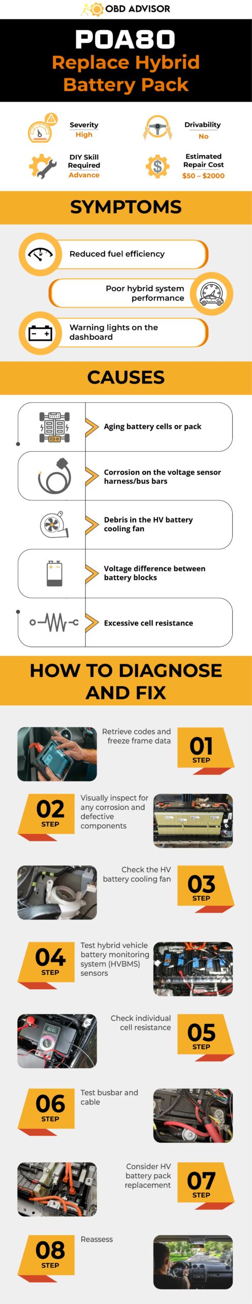
Final Thoughts
Once you’ve got the P0A80 code, it’s essential to have a grasp of and find solutions for this error code to ensure your vehicle maintains top-notch performance. By equipping yourself with the right tools and following the step-by-step procedure, you can confidently diagnose and repair hybrid battery issues. Remember, safety comes first, so if in doubt, consult a professional mechanic.
If you found this guide helpful, don’t hesitate to share it with fellow enthusiasts. Have questions or insights? Feel free to comment below – we’re here to help you keep your hybrid running smoothly.
Reference Sources
- OBD-Codes.com, P0A80 Error Code: Replace Hybrid Battery Pack
- National Highway Traffic Safety Administration (NHTSA), Technical Service Bulletin: MC-10131823-9999
- Synopsys, Battery Management System (BMS)
P0050 Code: Understanding Its Causes, Symptoms, and Repairs
P0050 Code: Understanding Its Causes, Symptoms, and Repairs
Hey there, fellow car enthusiasts and DIY mechanics! Have you ever come across the pesky P0050 error code on your car’s dashboard? Don’t panic! We’ve got your back. In this article, we’ll delve into the P0050 trouble code, specifically referring to the HO2S (Heated Oxygen Sensor) Heater Control Circuit related to Bank 2 Sensor 1. If you’ve encountered this code during a diagnostic scan, don’t worry. We’re here to help you understand its meaning, severity, symptoms, causes, necessary diagnosis and repair steps. So, let’s get started!
P0050 Code: Quick Overview
Here is an overview of the P0050 code. Take a look!
Definition: HO2S (Heated Oxygen Sensor) Heater Control Circuit Bank 2 Sensor 1
Severity: Medium
DIY Skill Level: Intermediate
Continue To Drive?: Yes (short-term)
Estimated Repair Cost: $100 – $300
What Does The P0050 Code Mean?
The P0050 code is triggered when the engine control module (ECM) detects an issue with the heater control circuit for Bank 2 Sensor 1. Bank 2 refers to the side of the engine that does not contain cylinder number one, while Sensor 1 denotes the upstream sensor located before the catalytic converter.
In modern vehicles, the engine management system relies on sensors to monitor various parameters and ensure optimal performance. One critical sensor is the oxygen sensor, also known as the HO2 sensor. Its primary function is to measure the oxygen content in the exhaust gases and provide feedback to the ECM for efficient fuel delivery and emissions control.
It’s important to note that the P0050 code is commonly associated with other related trouble codes, such as P0030, P0036, and P0056. These codes all indicate potential problems with the HO2S heater control circuit but may vary regarding the sensor position. Additionally, while the P0050 code can occur in various car brands, it is frequently found in vehicles such as Ford, Chevy (Silverado), BMW, and GMC.
How Severe Is P0050?
When it comes to the severity of the P0050 trouble code, it is considered a moderate issue. While this code doesn’t typically pose an immediate threat to your safety, it should not be ignored either due to its potential impact on fuel efficiency, engine performance, and emissions control.
It’s important not to drive for too long without fixing the P0050 code. While your vehicle may still operate, it’s important to address the underlying problem promptly to prevent potential long-term damage and ensure optimal engine performance. Taking proactive steps to resolve the P0050 code will help maintain your vehicle’s efficiency, performance, and overall reliability.
Read more: P0135 – O2 Sensor Heater Circuit Malfunction (Bank 1, Sensor 1)
Common Symptoms of P0050
The P0050 trouble code can cause various symptoms, including:
- Check Engine Light (MIL) illuminated
- Decreased fuel efficiency
- Rough idle or engine misfires
- Engine hesitation or stalling
- Failed emissions test
- Decreased engine performance
Causes of the P0050 Code
Several underlying causes can trigger the P0050 trouble code, including:
- Faulty HO2S heater control circuit
- Damaged or malfunctioning oxygen sensor
- Wiring or connector issues in the heater circuit
- Blown fuse related to the sensor heater
- Faulty ECM
Read more: P0161 – O2 Sensor Heater Circuit
How To Diagnosis And Fix The P0050 Code
When it comes to diagnosing and repairing the P0050 trouble code, it is essential to have the right tools and follow a systematic procedure. Let’s explore the necessary tools and parts, along with a step-by-step guide to resolving the code.
Essential Tools and Parts
- OBD-II scanner
- Digital multimeter
- Oxygen sensor socket
- Wire crimping tool
- Electrical contact cleaner
- Replacement oxygen sensor (if necessary)
- A test light
- Electrical connectors and wiring
Step-by-Step Procedure
Step 1: Retrieve the trouble codes and record freeze frame data
Use an OBD-II scanner to retrieve P0050 and any associated code. Take note of any freeze frame data, which provides additional information about the conditions when the code was triggered.
Step 2: Inspect the oxygen sensor wiring and connectors
Thoroughly examine the wiring and connectors associated with the affected oxygen sensor. Look for signs of damage, corrosion, or loose connections. Repair/clean if needed.
Step 3: Test the oxygen sensor heater circuit
Use a digital multimeter to check the resistance and voltage of the oxygen sensor heater circuit and compare it to the manufacturer’s specifications. If the reading is out of range, repair the circuit.
Step 4: Check the fuse related to the sensor heater
Locate the fuse responsible for the oxygen sensor heater circuit and inspect it for any signs of damage or blown fuse. Replace the fuse if necessary, ensuring it matches the proper specifications.
Step 5: Replace the oxygen sensor
Use a multimeter to test the oxygen sensor’s voltage. If the voltage is outside the range in the vehicle’s repair manual, it indicates it’s faulty. Replace the sensor following the manufacturer’s guidelines for proper installation and ensure the new sensor is compatible with your vehicle.
Step 6: Clear the codes and perform a road test
Once the repairs have been made, clear the trouble codes using an OBD-II scanner. Take the vehicle for a road test to ensure the P0050 code does not reappear and that the engine is running smoothly.
Notes:
- It’s recommended to consult the vehicle’s service manual for detailed instructions specific to your make and model.
- If you are unsure or uncomfortable with the diagnostic and repair procedures, it is best to seek assistance from a qualified mechanic.
DIY Repair Level and Estimated Costs
The diagnosis and repair of the P0050 code fall under intermediate-level repairs that require some technical knowledge. If you’re confident in your abilities, you can attempt the procedure. However, if you’re unsure or uncomfortable, it’s best to seek assistance from a professional mechanic.
Here’s a breakdown of the estimated costs for common repair tasks:
| Repair Task | Estimated Cost Range |
| Oxygen sensor replacement | $100 – $300 |
| Wiring or connector repair | $100 – $200 |
| Fuse replacement | $10 – $20 |
| Professional diagnostics | $80 – $150 (approx.) |
Please note that these approximate cost ranges can vary depending on the vehicle’s make and model, labor rates in your area, and the specific cause of the P0050 code. It’s always a good idea to consult a professional mechanic who can provide a more accurate estimate based on your circumstances.
Final Thoughts
Understanding the P0050 trouble code and its meaning can empower you to take the necessary knowledge for diagnosis and repair. By recognizing this code’s symptoms, causes, and severity, you can make informed decisions to maintain your vehicle’s performance and reliability.
Remember, if you’re confident in your DIY skills, you can attempt the repair procedure mentioned in this article. However, if you’re unsure or prefer the expertise of a professional, don’t hesitate to seek assistance from a qualified mechanic.
We hope this guide has shed light on the P0050 trouble code and provided valuable insights into its meaning and repair. If you found this article helpful, feel free to share it with others who may benefit. And if you have any questions or experiences to share, don’t hesitate to leave a comment below.
Safe travels and happy motoring!
Reference:
Freeasestudyguides. com – Heated Oxygen Sensors
P1299 Ford Code: Resolving Engine Overheating With Confidence
P1299 Ford Code: Resolving Engine Overheating With Confidence
Dealing with the P1299 Ford code in your vehicle? This comprehensive article provides valuable insights, symptoms, and effective repair methods to help you conquer the engine overheating issue. By following our expert guide, you’ll gain the knowledge and confidence to diagnose and resolve the P1299 code, ensuring optimal performance and reliability.
Read on to address the P1299 Ford code and take control of your vehicle’s cooling system.
P1299 Ford Code: An Overview
Take a look at a summary of the P1299 Ford code below:
- Definition: Cylinder Head Over-temperature Protection Active
- Severity: High
- DIY Skill Level: Intermediate
- Continue To Drive?: No
- Estimated Repair Cost: $20 – $300
What Does The P1299 Mean In Ford Vehicles?
The P1299 code is triggered when the Engine Control System detects engine overheating. It specifically relates to the Cylinder Head Temperature (CHT) sensor and monitoring circuit, which informs the Powertrain Control Module (PCM) about the engine’s temperature status.
The CHT sensor measures the temperature at the cylinder head and converts it into a signal voltage that varies with temperature fluctuations. Once the PCM receives a signal indicating that the engine temperature has exceeded the critical limit set by the manufacturer, it will set the P1299 code.
When the P1299 code is set, it may trigger Ford’s fail-safe cooling system, which is an engine protection feature that activates when the engine begins, to overheat. It reduces the risk of damage by shutting down some cylinders to lower heat production and pumping air through them to aid cooling. During this mode, engine power and performance are significantly reduced.
The P1299 diagnostic trouble code (DTC) commonly occurs in Ford vehicles across several models. Some of the popular models that may encounter this code include: Escape, Fusion, F-150, Edge, Expedition, and Explorer.
This P1299 code is often accompanied by additional codes that provide more specific information about the underlying issue. Some of the codes that might be found along with P1299 include: P0128, P0117, P0118, P0125, P0126, and P2560.
How Severe Is The P1299 Code In Ford Vehicles?
The P1299 Ford DTC indicates a potentially critical issue with the engine’s cooling system, specifically related to overheating. As such, it is considered a severe code that requires immediate attention.
If you encounter the P1299 code, it is strongly recommended not to continue driving the vehicle until the underlying issue is addressed. Continuing to drive with an overheating engine can exacerbate the problem and result in costly repairs. It is advisable to safely pull over, turn off the engine, and allow it to cool down before seeking professional assistance.
What Are The Signs Of The P1299 Ford Codes?
The P1299 Ford DTC is often accompanied by the following symptoms:
- Illuminated check engine light
- Engine overheating
- Reduced engine performance
- Engine running rough or misfiring
- Increased fuel consumption
- Possible engine stalling or failure to start
- Failsafe mode activation
Read more: B1352 Ford Code: Ignition Troubles Unveiled And Resolved
What Are The Causes Of The P1299 Code In Ford?
The P1299 Ford DTC can be caused by various factors, including:
- Malfunctioning CHT sensor
- Faulty cooling system components (thermostat or radiator)
- Low coolant level or coolant leaks
- Defective water pump
- Electrical issues in the CHT sensor circuit
- Contaminated engine oil
- Damaged cooling fan
These causes should be properly diagnosed and addressed to resolve the P1299 code.
P1299 Ford Code Diagnosis And Repair
In this section, we will address the repair and diagnosis of the P1299 Ford DTC. To effectively resolve this issue, you will need the following essential tools and parts:
Essential Tools And Parts
- OBD-II Scanner
- Multimeter
- Coolant Pressure Tester
- Replacement CHT Sensor
- Thermostat
- Radiator
- Water Pump
- Coolant
- Engine Oil
Step-by-Step Guide
- Begin by using an OBD-II scanner to retrieve the P1299 code and any additional codes present. Note the freeze frame data.
- Use a multimeter to check the CHT sensor circuit for electrical issues. Look for open circuits or short circuits and repair as necessary.
- Check the CHT sensor for physical damage or loose connections. Replace it if necessary.
- Inspect the cooling system components, including the thermostat, radiator, and water pump, for leaks, wear, or malfunction. Replace any faulty components.
- Ensure the coolant level is adequate. Top up the coolant if needed and inspect for leaks.
- Test the water pump for proper function. If it’s not circulating coolant effectively, replace it.
- Check the engine oil for signs of contamination. If present, replace the oil and address the underlying issue.
- Ensure the cooling fan operates correctly. Repair or replace the fan if needed.
- After making any necessary repairs, clear the diagnostic trouble codes and perform a road test to confirm that the issue has been resolved.
Read more: Ford OBD2 Codes List for FREE Download
DIY Repair Level And Estimated Costs
The level of DIY repair for the P1299 code varies from beginner to intermediate. If it’s a simple fix like changing the engine oil or topping up coolant, it can be a DIY task. However, more complex issues like replacing the water pump or radiator may require mechanical expertise.
Here’s an estimated cost breakdown for common repair tasks:
| Repair Task | Cost Range |
| Wirings repair | $20 – $150 |
| CHT Sensor replacement | $20 – $50 |
| Thermostat replacement | $20 – $50 |
| Radiator replacement | $100 – $300 |
| Water pump replacement | $50 – $150 |
| Coolant top up | $10 – $20 |
| Engine oil change | $30 – $50 |
It’s crucial to diagnose the specific cause of the P1299 code accurately to avoid unnecessary expenses. If you’re uncertain about the repair, consult a professional mechanic for assistance.
Conclusion
Resolving the P1299 Ford code and getting your vehicle back on the road is a reachable goal. Armed with the knowledge and steps we’ve provided, you can confidently diagnose and address this issue. Don’t keep this valuable information to yourself – share it with fellow Ford owners who might be facing the same challenge.
Do you have questions or success stories to share? We’re all ears! Feel free to drop your experiences and insights in the comments section below.
Reference Sources
- Professional Automotive Repair, What is Engine Misfiring? Does It Affect Your Car?
- Goodyear Auto Service, Engine Overheating Causes and Actions.
P2118 Code: A Guide to Throttle Actuator Control Motor Issues
P2118 Code: A Guide to Throttle Actuator Control Motor Issues
Welcome to our comprehensive guide on the P2118 engine code, a common issue related to throttle actuator control motors.
If you’ve encountered this code, you’re not alone. In this article, we’ll explore the meaning, severity, symptoms, causes, and diagnostic process for P2118. We aim to equip you with the knowledge to understand this code and its implications for your vehicle’s performance.
So, let’s dive in!
P2118 Code: A Quick Overview
Here is an overview of the P2118 code. Let’s take a look!
- Definition: Throttle Actuator Control Motor Current Range/Performance
- Severity: High
- DIY Skill Level: Intermediate
- Continue To Drive?: No
- Estimated Repair Cost: $100 – $500
What Does The P2118 Mean?
The P2118 engine code indicates a malfunction in the operation of the Throttle Actuator Control System. This system is responsible for regulating the airflow into the engine by controlling the position of the throttle plate.
When the Powertrain Control Module (PCM) detects an issue with this system, such as voltage readings or performance outside the expected range, it triggers the P2118 code. This serves as a warning that there may be a problem with the current range and performance of the throttle actuator control motor.
It’s worth noting that the P2118 code is commonly found in various car brands, including Toyota, Lexus, Ford, KIA, and Hyundai. Additionally, it is often associated with codes P2102, P2103, P2107, P2108, P2110, P2111, and P2119, which relate to the throttle actuator control system.
Read more: P0122 – Throttle/Pedal Position Sensor/Switch “A” Circuit Low
Can You Still Drive With The Code P2118?
The P2118 engine code is considered a high severity level. This code directly affects the engine’s performance and drivability, so it should not be overlooked.
Driving with the P2118 code present can result in severe consequences. The engine may experience reduced power, poor acceleration, and potentially even stalling. These issues can compromise the safety of both the driver and the vehicle.
So, it is strongly advised not to continue driving with the P2118 code unresolved. Instead, it is essential to diagnose and repair the underlying problem as soon as possible. Promptly addressing this code will restore optimal throttle actuator control system function, ensuring the safe and efficient operation of your vehicle.
Signs Of The P2118 Code
Here are some common symptoms typically seen with this code:
- Illuminated check engine light, TRAC OFF light
- Limp mode (Fail-safe mode)
- Reduced engine power or lack of acceleration
- Engine stalling or rough idle
- Hard starting
- Little or no throttle response
Causes Of The P2118 Code
Here are some possible triggers:
- Faulty throttle actuator control motor
- Issues with the throttle body or throttle position sensor
- Defective accelerator pedal position sensor
- Wiring or electrical connection problems
- Blown throttle actuator control motor’s fuse
- Malfunctioning PCM
How Do I Diagnose And Fix The P2118 Code?
In this section, we will explore the essential tools and parts required for diagnosing and repairing the P2118 code, provide a step-by-step procedure to address the issue and discuss the level of DIY repair along with estimated costs.
Essential Tools and Parts
- OBD-II scanner
- Multimeter
- Throttle actuator control motor replacement (if necessary)
- Throttle body cleaner
- Electrical contact cleaner
- Wire connectors and electrical tape
Step-by-Step Procedure
- Retrieve the trouble codes using an OBD-II scanner.
- Check the throttle actuator control motor’s fuse on the junction box with a test light. Replace the fuse if it doesn’t work properly.
- Inspect the throttle body and wiring connections for any signs of damage or loose connections. Clean/repair it if needed.
- Check other components related to the Throttle Actuator Control System, such as the throttle position sensor and accelerator pedal position sensor, to ensure it works properly. Replace any faulty components if it’s bad.
- Test the throttle actuator control motor’s voltage using a multimeter. If the voltage is outside the range in the vehicle’s repair manual, replace it with a new one.
- Inspect the electrical wiring and connections associated with the throttle actuator control system. Clean/replace it if you see any dirt or damage.
- Clear codes and test drive to ensure the issue has been resolved.
Note:
- It is recommended to consult the vehicle’s repair manual for detailed instructions specific to your make and model.
- Double-check all before reassembling.
DIY Repair Level And Estimated Costs
Regarding the P2118 code, tasks like cleaning the throttle body and changing the car fuse are within the capabilities of most DIY enthusiasts. However, replacing the throttle actuator control motor may require advanced knowledge and specialized tools, making it better suited for individuals with intermediate to advanced DIY skills.
Here’s a breakdown of estimated costs for the main repair tasks to repair the P2118 code:
| Repair Task | Estimated Cost |
| Wiring Repairs | $50 – $150 |
| Blown Fuse Replacement | $50 – $100 |
| Throttle Body Cleaning | $10 – $30 |
| Throttle Actuator Control Motor Replacement | $150 – $500 |
Please note that these estimated costs are approximate and can vary depending on the vehicle’s make, model, and location. Additionally, prices for parts and labor can vary among different service providers. It’s always recommended to obtain quotes from reputable mechanics or parts suppliers for a more accurate estimate based on your specific circumstances.
Final Thoughts
In conclusion, the P2118 engine code indicates a significant issue with the throttle actuator control motor’s current range and performance. Ignoring this code can lead to reduced engine power, stalling, and compromised driving safety. Prompt action is crucial.
If you’re experiencing the symptoms associated with the P2118 code, it’s essential to diagnose and address the underlying problem. While DIY enthusiasts can tackle some tasks, assistance from a qualified mechanic is advisable for complex repairs.
We hope this guide has provided valuable insights into the P2118 code. If you found it helpful, feel free to share it with others. If you have any questions or comments, please leave them below.
Safe and smooth driving!
Reference:
- Wikipedia – Electronic throttle control
- Toyota – T-TT-0321-15 TSB
- Toyota 20RAV4 – Repair Manual
Ford OBD2 Codes List for FREE Download
Ford OBD2 Codes List for FREE Download
Is your Ford’s Check Engine light on?
Don’t panic – our FREE comprehensive list of OBD2 codes can help you quickly diagnose your car issues. Whether you’re a seasoned DIY enthusiast or a novice looking to learn more about your Ford’s diagnostics, this list has got you covered.
So, don’t miss out – read until the end!
Ford OBD2 Codes List and Meaning [FULL]
Free Download: Full Ford OBD2 Trouble Codes List and Meaning PDF
Our user-friendly code list is divided into four parts: Powertrain, Network, Body, and Chassis, which helps you easily find the codes you need for engine, network, body control, and chassis issues.
Note: Use the search box in the table below to quickly find the specific code you’re looking for.
Powertrain (P) Codes List
| Code | Definition |
|---|---|
| P0100 | Mass Air Flow Circuit Malfunction |
| P0101 | Mass Air Flow Circuit Range/Performance Problem |
| P0102 | MAF Circuit Low Input |
| P0103 | MAF Circuit High Input |
| P0104 | MAF Circuit Intermittent |
| P0105 | MAP/BP Circuit Malfunction |
| P0106 | MAP/BP Sensor Range/Performance Problem |
| P0107 | MAP/BP Sensor Low Input |
| P0108 | MAP/BP Sensor High Input |
| P0109 | MAP/BP Circuit Intermittent |
| P0110 | IAT Circuit Malfunction |
| P0111 | IAT Circuit Range/Performance Problem |
| P0112 | IAT Circuit Low Input |
| P0113 | IAT Circuit High Input |
| P0114 | IAT Circuit Intermittent |
| P0115 | ECT Circuit Malfunction |
| P0116 | ECT Circuit Range/Performance Problem |
| P0117 | ECT Circuit Low Input |
| P0118 | ECT Circuit High Input |
| P0119 | ECT Intermittent |
| P0120 | TP Sensor A Circuit Malfunction |
| P0121 | TP Sensor A Circuit Range/Performance Problem |
| P0122 | TP Sensor A Circuit Low Input |
| P0123 | TP Sensor A Circuit High Input |
| P0124 | TP Sensor A Circuit Intermittent |
| P0125 | Insufficient Coolant Temp For Closed Loop Fuel Control |
| P0126 | Insufficient Coolant Temp For Stable Operation |
| P0128 | Coolant Thermostat Malfunction |
| P0130 | Heated O2 Sensor Circuit Malfunction (Bank 1, Sensor 1) |
| P0131 | Heated O2 Circuit Low Voltage (Bank 1, Sensor 1) |
| P0132 | Heated O2 Sensor Circuit High Voltage (Bank 1, Sensor 1) |
| P0133 | Heated O2 Sensor Circuit Slow Response (Bank 1, Sensor 1) |
| P0134 | Heated O2 Sensor Circuit No Activity Detected (Bank 1, Sensor 1) |
| P0135 | Heated O2 Sensor Heater Circuit Malfunction (Bank 1, Sensor 1) |
| P0136 | Heated O2 Sensor Circuit Malfunction (Bank 1, Sensor 2) |
| P0137 | Heated O2 Sensor Circuit Low Voltage (Bank 1, Sensor 2) |
| P0138 | Heated O2 Sensor Circuit High Voltage (Bank 1, Sensor 2) |
| P0139 | Heated O2 Sensor Circuit Slow Response (Bank 1, Sensor 2) |
| P0140 | Heated O2 Sensor Circuit No Activity Detected (Bank 1, Sensor 2) |
| P0141 | Heated O2 Sensor Heater Circuit Malfunction (Bank 1, Sensor 2) |
| P0142 | Heated O2 Sensor Circuit Malfunction (Bank 1, Sensor 3) |
| P0143 | Heated O2 Sensor Circuit Low Voltage (Bank 1, Sensor 3) |
| P0144 | Heated O2 Sensor Circuit High Voltage (Bank 1, Sensor 3) |
| P0145 | Heated O2 Sensor Circuit Slow Response (Bank 1, Sensor 3) |
| P0146 | Heated O2 Sensor Circuit No Activity Detected (Bank 1, Sensor 3) |
| P0147 | Heated O2 Sensor Heater Circuit Malfunction (Bank 1, Sensor 3) |
| P0150 | Heated O2 Sensor Circuit Malfunction (Bank 2, Sensor 1) |
| P0151 | Heated O2 Sensor Circuit Low Voltage (Bank 2, Sensor 1) |
| P0152 | Heated O2 Sensor Circuit High Voltage (Bank 2, Sensor 1) |
| P0153 | Heated O2 Sensor Circuit Slow Response (Bank 2, Sensor 1) |
| P0154 | Heated O2 Sensor Circuit No Activity Detected (Bank 2, Sensor 1) |
| P0155 | Heated O2 Sensor Heater Circuit Malfunction (Bank 2, Sensor 1) |
| P0156 | Heated O2 Sensor Circuit Malfunction (Bank 2, Sensor 1) |
| P0157 | Heated O2 Sensor Circuit Low Voltage (Bank 2, Sensor 2) |
| P0158 | Heated O2 Sensor Circuit High Voltage (Bank 2, Sensor 2) |
| P0159 | Heated O2 Sensor Circuit Slow Response (Bank 2, Sensor 2) |
| P0160 | Heated O2 Sensor Circuit No Activity Detected (Bank 2, Sensor 2) |
| P0161 | Heated O2 Sensor Heater Circuit Malfunction (Bank 2, Sensor 2) |
| P0170 | Fuel Trim Malfunction (Bank 1) |
| P0171 | System Too Lean (Bank 1) |
| P0172 | System Too Rich (Bank 1) |
| P0173 | Fuel Trim Malfunction (Bank 2) |
| P0174 | System Too Lean (Bank 2) |
| P0175 | System Too Rich (Bank 2) |
| P0176 | Fuel Composition Sensor Circuit Fault |
| P0177 | Fuel Composition Sensor Circuit Range/Performance |
| P0178 | Fuel Composition Sensor Circuit Low Input |
| P0179 | Fuel Composition Sensor Circuit High Input |
| P0180 | Fuel Temperature Sensor A Circuit Malfunction |
| P0181 | Fuel Temperature Sensor A Circuit Range/Performance |
| P0182 | Fuel Temperature Sensor A Circuit Low Input |
| P0183 | Fuel Temperature Sensor A Circuit High Input |
| P0184 | Fuel Temperature Sensor A Circuit Intermittent |
| P0185 | Fuel Temperature Sensor B Circuit Malfunction |
| P0186 | Fuel Temperature Sensor B Circuit Range/Performance |
| P0187 | Fuel Temperature Sensor B Circuit Low Input |
| P0188 | Fuel Temperature Sensor B Circuit High Input |
| P0189 | Fuel Temperature Sensor B Circuit Intermittent |
| P0190 | Fuel Rail Pressure Sensor Circuit Malfunction |
| P0191 | Fuel Rail Pressure Sensor Circuit Range/Performance |
| P0192 | Fuel Rail Pressure Sensor Circuit Low Input |
| P0193 | Fuel Rail Pressure Sensor Circuit High Input |
| P0195 | Engine Oil Temperature Sensor Circuit Malfunction |
| P0196 | Engine Oil Temperature Sensor Range/Performance |
| P0197 | Engine Oil Temperature Sensor Low |
| P0198 | Engine Oil Temperature Sensor High |
| P0199 | Engine Oil Temperature Sensor Intermittent |
| P0200 | Injector Circuit Malfunction |
| P0201 | Injector Circuit Malfunction – Cylinder #1 |
| P0202 | Injector Circuit Malfunction – Cylinder #2 |
| P0203 | Injector Circuit Malfunction – Cylinder #3 |
| P0204 | Injector Circuit Malfunction – Cylinder #4 |
| P0205 | Injector Circuit Malfunction – Cylinder #5 |
| P0206 | Injector Circuit Malfunction – Cylinder #6 |
| P0207 | Injector Circuit Malfunction – Cylinder #7 |
| P0208 | Injector Circuit Malfunction – Cylinder #8 |
| P0209 | Injector Circuit Malfunction – Cylinder #9 |
| P0210 | Injector Circuit Malfunction – Cylinder #10 |
| P0211 | Injector Circuit Malfunction – Cylinder #11 |
| P0212 | Injector Circuit Malfunction – Cylinder #12 |
| P0213 | Cold Start Injector #1 Malfunction |
| P0214 | Cold Start Injector #2 Malfunction |
| P0215 | Engine Shutoff Solenoid Malfunction |
| P0216 | Injection Timing Control Circuit Malfunction |
| P0217 | Engine Overtemp Condition |
| P0218 | Transmission Overtemp Condition |
| P0219 | Engine Overspeed Condition |
| P0220 | Throttle/Pedal Position Sensor/Switch B Circuit Malfunction |
| P0221 | Throttle/Pedal Position Sensor/Switch B Performance Problem |
| P0222 | Throttle Position Sensor B Circuit Low Input |
| P0223 | Throttle Position Sensor B Circuit High Input |
| P0224 | Throttle Position Sensor B Intermittent |
| P0225 | Throttle Position Sensor C Circuit Malfunction |
| P0227 | Throttle Position Sensor C Circuit Low Input |
| P0228 | Throttle Position Sensor C Circuit High Input |
| P0229 | Throttle Position Sensor C Intermittent |
| P0230 | Fuel Pump Primary Circuit Malfunction |
| P0231 | Fuel Pump Secondary Circuit Low |
| P0232 | Fuel Pump Secondary Circuit High |
| P0233 | Fuel Pump Secondary Circuit Intermittent |
| P0234 | Engine Overboost Condition |
| P0235 | Turbocharger Boost Sensor A Circuit Malfunction |
| P0236 | Turbocharger Boost Sensor A Performance |
| P0237 | Turbocharger Boost Sensor A Circuit Low |
| P0238 | Turbocharger Boost Sensor A Circuit High |
| P0239 | Turbocharger Boost Sensor B Circuit Malfunction |
| P0240 | Turbocharger Boost Sensor B Circuit Range/Performance |
| P0241 | Turbocharger Boost Sensor B Circuit Low |
| P0242 | Turbocharger Boost Sensor B Circuit High |
| P0243 | Wastegate Solenoid A Malfunction |
| P0244 | Wastegate Solenoid A Range/Performance |
| P0245 | Wastegate Solenoid A Low |
| P0246 | Wastegate Solenoid A High |
| P0247 | Wastegate Solenoid B Malfunction |
| P0248 | Wastegate Solenoid B Range/Performance |
| P0249 | Wastegate Solenoid B Low |
| P0250 | Wastegate Solenoid B High |
| P0251 | Injection Pump Fuel Metering Control A Malfunction |
| P0252 | Injection Pump Fuel Metering Control A Range/Performance |
| P0253 | Injection Pump Fuel Metering Control A Low |
| P0254 | Injection Pump Fuel Metering Control A High |
| P0255 | Injection Pump Fuel Metering Control A Intermittent |
| P0256 | Injection Pump Fuel Metering Control B Malfunction |
| P0257 | Injection Pump Fuel Metering Control B Range/Performance |
| P0258 | Injection Pump Fuel Metering Control B Low |
| P0259 | Injection Pump Fuel Metering Control B High |
| P0260 | Injection Pump Fuel Metering Control B Intermittent |
| P0261 | Injector Circuit Low – Cylinder #1 |
| P0262 | Injector Circuit High – Cylinder #1 |
| P0263 | Cylinder #1 Balance Fault |
| P0264 | Injector Circuit Low – Cylinder #2 |
| P0265 | Injector Circuit High – Cylinder #2 |
| P0266 | Cylinder #2 Balance Fault |
| P0267 | Injector Circuit Low – Cylinder #3 |
| P0268 | Injector Circuit High – Cylinder #3 |
| P0269 | Cylinder #3 Balance Fault |
| P0270 | Injector Circuit Low – Cylinder #4 |
| P0271 | Injector Circuit High – Cylinder #4 |
| P0272 | Cylinder #4 Balance Fault |
| P0273 | Injector Circuit Low – Cylinder #5 |
| P0274 | Injector Circuit High – Cylinder #5 |
| P0275 | Cylinder #5 Balance Fault |
| P0276 | Injector Circuit Low – Cylinder #6 |
| P0277 | Injector Circuit High – Cylinder #6 |
| P0278 | Cylinder #6 Balance Fault |
| P0279 | Injector Circuit Low – Cylinder #7 |
| P0280 | Injector Circuit High – Cylinder #7 |
| P0281 | Cylinder #7 Balance Fault |
| P0282 | Injector Circuit Low – Cylinder #8 |
| P0283 | Injector Circuit High – Cylinder #8 |
| P0284 | Cylinder #8 Balance Fault |
| P0285 | Injector Circuit Low – Cylinder #9 |
| P0286 | Injector Circuit High – Cylinder #9 |
| P0287 | Cylinder #9 Balance Fault |
| P0288 | Injector Circuit Low – Cylinder #10 |
| P0289 | Injector Circuit High – Cylinder #10 |
| P0290 | Cylinder #10 Balance Fault |
| P0291 | Injector Circuit Low – Cylinder #11 |
| P0292 | Injector Circuit High – Cylinder #11 |
| P0293 | Cylinder #11 Balance Fault |
| P0294 | Injector Circuit Low – Cylinder #12 |
| P0295 | Injector Circuit High – Cylinder #12 |
| P0296 | Cylinder #12 Balance Fault |
| P0300 | Random Misfire Detected |
| P0301 | Cylinder #1 Misfire Detected |
| P0302 | Cylinder #2 Misfire Detected |
| P0303 | Cylinder #3 Misfire Detected |
| P0304 | Cylinder #4 Misfire Detected |
| P0305 | Cylinder #5 Misfire Detected |
| P0306 | Cylinder #6 Misfire Detected |
| P0307 | Cylinder #7 Misfire Detected |
| P0308 | Cylinder #8 Misfire Detected |
| P0309 | Cylinder #9 Misfire Detected |
| P0310 | Cylinder #10 Misfire Detected |
| P0311 | Cylinder #11 Misfire Detected |
| P0312 | Cylinder #12 Misfire Detected |
| P0320 | Ignition Engine Speed Input Circuit Malfunction |
| P0321 | Ignition Engine Speed Input Circuit Range/Performance |
| P0322 | Ignition Engine Speed Input Circuit No Signal |
| P0323 | Ignition Engine Speed Input Circuit Intermittent |
| P0325 | Knock Sensor 1 Circuit Malfunction |
| P0326 | Knock Sensor 1 Circuit Range/Performance |
| P0327 | Knock Sensor 1 Circuit Low Input |
| P0328 | Knock Sensor 1 Circuit High Input |
| P0329 | Knock Sensor 1 Circuit Intermittent |
| P0330 | Knock Sensor 2 Circuit Malfunction |
| P0331 | Knock Sensor 2 Circuit Range/Performance |
| P0332 | Knock Sensor 2 Circuit Low Input |
| P0333 | Knock Sensor 2 Circuit High Input |
| P0334 | Knock Sensor 2 Circuit Intermittent |
| P0335 | Crankshaft Position Sensor A Circuit Malfunction |
| P0336 | Crankshaft Position Sensor A Circuit Range/Performance |
| P0337 | Crankshaft Position Sensor A Circuit Low Input |
| P0338 | Crankshaft Position Sensor A Circuit High Input |
| P0339 | Crankshaft Position Sensor A Circuit Intermittent |
| P0340 | Camshaft Position Sensor Circuit Malfunction |
| P0341 | Camshaft Position Sensor Circuit Performance |
| P0342 | Camshaft Position Sensor Circuit Low Input |
| P0343 | Camshaft Position Sensor Circuit High Input |
| P0344 | Camshaft Position Sensor Circuit Intermittent |
| P0350 | Ignition Coil Primary / Secondary Circuit Malfunction |
| P0351 | Ignition Coil Primary A / Secondary Circuit Malfunction |
| P0352 | Ignition Coil Primary B / Secondary Circuit Malfunction |
| P0353 | Ignition Coil Primary C / Secondary Circuit Malfunction |
| P0354 | Ignition Coil Primary D / Secondary Circuit Malfunction |
| P0355 | Ignition Coil Primary E / Secondary Circuit Malfunction |
| P0356 | Ignition Coil Primary F / Secondary Circuit Malfunction |
| P0357 | Ignition Coil Primary G / Secondary Circuit Malfunction |
| P0358 | Ignition Coil Primary H / Secondary Circuit Malfunction |
| P0359 | Ignition Coil Primary I / Secondary Circuit Malfunction |
| P0360 | Ignition Coil Primary J / Secondary Circuit Malfunction |
| P0361 | Ignition Coil Primary K / Secondary Circuit Malfunction |
| P0362 | Ignition Coil Primary L / Secondary Circuit Malfunction |
| P0370 | Timing Reference High Resolution Signal A Malfunction |
| P0371 | Timing Reference High Resolution Signal A Too Many Pulses |
| P0372 | Timing Reference High Resolution Signal A Too Few Pulses |
| P0373 | Timing Reference High Resolution Signal A Intermittent |
| P0374 | Timing Reference High Resolution Signal A No Pulses |
| P0375 | Timing Reference High Resolution Signal B Malfunction |
| P0376 | Timing Reference High Resolution Signal B Too Many Pulses |
| P0377 | Timing Reference High Resolution Signal B Too Few Pulses |
| P0378 | Timing Reference High Resolution Signal B Intermittent |
| P0379 | Timing Reference High Resolution Signal B No Pulses |
| P0380 | Glow Plug Circuit A Malfunction |
| P0381 | Glow Plug Indicator Circuit Malfunction |
| P0382 | Glow Plug Circuit B Malfunction |
| P0385 | Crankshaft Position Sensor B Circuit Malfunction |
| P0386 | Crankshaft Position Sensor B Circuit Range/Performance |
| P0387 | Crankshaft Position Sensor B Circuit Low Input |
| P0388 | Crankshaft Position Sensor B Circuit High Input |
| P0389 | Crankshaft Position Sensor B Circuit Intermittent |
| P0400 | EGR Flow Malfunction |
| P0401 | EGR Flow Insufficient Detected |
| P0402 | EGR Flow Excessive Detected |
| P0403 | EGR Circuit Malfunction |
| P0404 | EGR Circuit Range/Performance |
| P0405 | EGR Sensor A Circuit Low Input |
| P0406 | EGR Sensor A Circuit High Input |
| P0407 | EGR Sensor B Circuit Low Input |
| P0408 | EGR Sensor B Circuit High Input |
| P0410 | SAI System Malfunction |
| P0411 | SAI System Incorrect Upstream Flow Detected |
| P0412 | SAI System Switching Valve A Circuit Malfunction |
| P0413 | SAI System Switching Valve A Circuit Open |
| P0414 | SAI System Switching Valve A Circuit Shorted |
| P0415 | SAI System Switching Valve B Circuit Malfunction |
| P0416 | SAI System Switching Valve B Circuit Open |
| P0417 | SAI System Switching Valve B Circuit Shorted |
| P0418 | SAI System Relay A Circuit Malfunction |
| P0419 | SAI System Relay B Circuit Malfunction |
| P0420 | Catalyst System Efficiency Below Threshold (Bank 1) |
| P0421 | Warm Up Catalyst Efficiency Below Threshold (Bank 1) |
| P0422 | Main Catalyst Efficiency Below Threshold (Bank 1) |
| P0423 | Heated Catalyst Efficiency Below Threshold (Bank 1) |
| P0424 | Heated Catalyst Temperature Below Threshold (Bank 1) |
| P0426 | Catalyst Temperature Sensor Range/Performance (Bank 1) |
| P0427 | Catalyst Temperature Sensor Low Input (Bank 1) |
| P0428 | Catalyst Temperature Sensor High Input (Bank 1) |
| P0430 | Catalyst System Efficiency Below Threshold (Bank 2) |
| P0431 | Warm Up Catalyst Efficiency Below Threshold (Bank 2) |
| P0432 | Main Catalyst Efficiency Below Threshold (Bank 2) |
| P0433 | Heated Catalyst Efficiency Below Threshold (Bank 2) |
| P0434 | Heated Catalyst Temperature Below Threshold (Bank 2) |
| P0436 | Catalyst Temperature Sensor Range/Performance (Bank 2) |
| P0437 | Catalyst Temperature Sensor Low Input (Bank 2) |
| P0438 | Catalyst Temperature Sensor High Input (Bank 2) |
| P0440 | Evaporative Emission Control System Malfunction |
| P0441 | Evaporative Emission Control System Incorrect Purge Flow |
| P0442 | Evaporative Emission Control System Leak Detected |
| P0443 | Evap Emission Control System Purge Control Circuit Malf. |
| P0444 | Evap Emission Control Sys Purge Control Valve Circuit Open |
| P0445 | Evap Emission Control Sys Purge Control Valve Circuit Short |
| P0446 | Evap Emission Control System Vent Malfunction |
| P0447 | Evap Emission Control System Vent Circuit Open |
| P0448 | Evap Emission Control System Vent Circuit Shorted |
| P0449 | Evap Emission Control System Vent Circuit Intermittent |
| P0450 | Evap Emission Control System Pressure Sensor Malfunction |
| P0451 | Evap Emission Control System Pressure Sensor Performance |
| P0452 | Evap Emission Control System Pressure Sensor Low Input |
| P0453 | Evap Emission Control System Pressure Sensor High Input |
| P0454 | Evap Emission Control System Pressure Sensor Intermittent |
| P0455 | Evap Emission Control System Leak Detected (Gross Leak/No Flow) |
| P0460 | Fuel Level Sensor Circuit Malfunction |
| P0461 | Fuel Level Sensor Circuit Range/Performance |
| P0462 | Fuel Level Sensor Circuit Low Input |
| P0463 | Fuel Level Sensor Circuit High Input |
| P0464 | Fuel Level Sensor Circuit Intermittent |
| P0465 | Purge Flow Sensor Circuit Malfunction |
| P0466 | Purge Flow Sensor Circuit Range/Performance |
| P0467 | Purge Flow Sensor Circuit Low Input |
| P0468 | Purge Flow Sensor Circuit High Input |
| P0469 | Purge Flow Sensor Circuit Intermittent |
| P0470 | Exhaust Pressure Sensor Circuit Malfunction |
| P0471 | Exhaust Pressure Sensor Circuit Range/Performance |
| P0472 | Exhaust Pressure Sensor Low |
| P0473 | Exhaust Pressure Sensor High |
| P0474 | Exhaust Pressure Sensor Intermittent |
| P0475 | Exhaust Pressure Control Valve Malfunction |
| P0476 | Exhaust Pressure Control Valve Performance |
| P0477 | Exhaust Pressure Control Valve Low |
| P0478 | Exhaust Pressure Control Valve High |
| P0479 | Exhaust Pressure Control Valve Intermittent |
| P0480 | Cooling Fan 1 Control Circuit Malfunction |
| P0481 | Cooling Fan 2 Control Circuit Malfunction |
| P0482 | Cooling Fan 3 Control Circuit Malfunction |
| P0483 | Cooling Fan Rationality Check Malfunction |
| P0484 | Cooling Fan Circuit Over Current |
| P0485 | Cooling Fan Power/Ground Circuit Malfunction |
| P0500 | Vehicle Speed Sensor Malfunction |
| P0501 | Vehicle Speed Sensor Range/Performance |
| P0502 | Vehicle Speed Sensor Low Input |
| P0503 | Vehicle Speed Sensor Intermittent |
| P0505 | Idle Air Control System Malfunction |
| P0506 | Idle Air Control System RPM Lower Than Expected |
| P0507 | Idle Air Control System RPM Higher Than Expected |
| P0510 | Closed Throttle Position Switch Malfunction |
| P0520 | Engine Oil Pressure Sensor/Switch Circuit Malfunction |
| P0521 | Engine Oil Pressure Sensor/Switch Circuit Range/Performance |
| P0522 | Engine Oil Pressure Sensor/Switch Circuit Low Input |
| P0523 | Engine Oil Pressure Sensor/Switch Circuit High Input |
| P0530 | A/C Refrigerant Pressure Sensor Circuit Malfunction |
| P0531 | A/C Refrigerant Pressure Sensor Circuit Range/Performance |
| P0532 | A/C Refrigerant Pressure Sensor Circuit Low Input |
| P0533 | A/C Refrigerant Pressure Sensor Circuit High Input |
| P0534 | A/C Refrigerant Charge Loss |
| P0550 | Power Steering Pressure Sensor Circuit Malfunction |
| P0551 | Power Steering Pressure Sensor Circuit Range/Performance |
| P0552 | Power Steering Pressure Sensor Circuit Low Input |
| P0553 | Power Steering Pressure Sensor Circuit High Input |
| P0554 | Power Steering Pressure Sensor Circuit Intermittent |
| P0560 | System Voltage Malfunction |
| P0561 | System Voltage Unstable |
| P0562 | System Voltage Low |
| P0563 | System Voltage High |
| P0565 | Cruise ON Signal Malfunction |
| P0566 | Cruise OFF Signal Malfunction |
| P0567 | Cruise RESUME Signal Malfunction |
| P0568 | Cruise SET Signal Malfunction |
| P0569 | Cruise COAST Signal Malfunction |
| P0570 | Cruise ACCEL Signal Malfunction |
| P0571 | Cruise Brake Switch Circuit Malfunction |
| P0572 | Cruise Brake Switch Circuit Low |
| P0573 | Cruise Brake Switch Circuit High |
| P0600 | Serial Communications Link Malfunction |
| P0601 | Internal Control Module Memory Check Sum Error |
| P0602 | Control Module Programming Error |
| P0603 | Powertrain Control Module KAM Test Error |
| P0604 | Powertrain Control Module RAM Test Error |
| P0605 | Powertrain Control Module ROM Test Error |
| P0606 | PCM Processor Fault |
| P0608 | PCM VSS Output A Malfunction |
| P0609 | PCM VSS Output B Malfunction |
| P0620 | Generator Control Circuit Malfunction |
| P0621 | Generator Lamp “L” Control Circuit Malfunction |
| P0622 | Generator Field “F” Control Circuit Malfunction |
| P0650 | MIL Control Circuit Malfunction |
| P0700 | Transmission Control System Malfunction |
| P0701 | Transmission Control System Range/Performance |
| P0702 | Transmission Control System Electrical |
| P0703 | Brake Switch Input Malfunction |
| P0704 | Clutch Switch Input Circuit Malfunction |
| P0705 | Transmission Range Sensor Circuit Malfunction |
| P0706 | Transmission Range Sensor Circuit Range/Performance |
| P0707 | Transmission Range Sensor Circuit Low Input |
| P0708 | Transmission Range Sensor Circuit High Input |
| P0709 | Transmission Range Sensor Circuit Intermittent |
| P0710 | Transmission Fluid Temperature Sensor Circuit Malfunction |
| P0711 | Transmission Fluid Temperature Sensor Circuit Range/Perf |
| P0712 | Transmission Fluid Temp Sensor Circuit Low Input |
| P0713 | Transmission Fluid Temp Sensor Circuit High Input |
| P0714 | Transmission Fluid Temp Sensor Circuit Intermittent |
| P0715 | Turbine Speed Sensor Circuit Malfunction |
| P0716 | Turbine Speed Sensor Circuit Range/Performance |
| P0717 | Turbine Speed Sensor Circuit No Signal |
| P0718 | Turbine Speed Sensor Circuit Intermittent |
| P0719 | Torque Converter/Brake Switch B Circuit Low |
| P0720 | Output Shaft Speed Sensor Circuit Malfunction |
| P0721 | Output Shaft Speed Sensor No Performance |
| P0722 | Output Shaft Speed Sensor No Signal |
| P0723 | Output Shaft Speed Sensor Intermittent |
| P0724 | Torque Converter/Brake Switch B Circuit High |
| P0725 | Engine Speed Input Circuit Malfunction |
| P0726 | Engine Speed Input Circuit Range/Performance |
| P0727 | Engine Speed Input Circuit No Signal |
| P0728 | Engine Speed Input Circuit Intermittent |
| P0730 | Incorrect Gear Ratio |
| P0731 | Gear 1 Incorrect Ratio |
| P0732 | Gear 2 Incorrect Ratio |
| P0733 | Gear 3 Incorrect Ratio |
| P0734 | Gear 4 Incorrect Ratio |
| P0735 | Gear 5 Incorrect Ratio |
| P0736 | Reverse Incorrect Ratio |
| P0740 | Torque Converter Clutch Circuit Malfunction |
| P0741 | Torque Converter Clutch System Performance Or Stuck Off |
| P0742 | Torque Converter Clutch Circuit Stuck On |
| P0743 | Torque Converter Clutch System Electrical |
| P0744 | Torque Converter Clutch Circuit Intermittent |
| P0745 | Pressure Control Solenoid A Malfunction |
| P0746 | Pressure Control Solenoid A Performance or Stuck Off |
| P0747 | Pressure Control Solenoid A Stuck On |
| P0748 | Pressure Control Solenoid A Electrical |
| P0749 | Pressure Control Solenoid A Intermittent |
| P0750 | Shift Solenoid A Malfunction |
| P0751 | Shift Solenoid A Performance |
| P0752 | Shift Solenoid A Stuck On |
| P0753 | Shift Solenoid A Electrical |
| P0754 | Shift Solenoid A Intermittent |
| P0755 | Shift Solenoid B Malfunction |
| P0756 | Shift Solenoid B Performance |
| P0757 | Shift Solenoid B Stuck On |
| P0758 | Shift Solenoid B Electrical |
| P0759 | Shift Solenoid B Intermittent |
| P0760 | Shift Solenoid C Malfunction |
| P0761 | Shift Solenoid C Performance |
| P0762 | Shift Solenoid C Stuck On |
| P0763 | Shift Solenoid C Electrical |
| P0764 | Shift Solenoid C Intermittent |
| P0765 | Shift Solenoid D Malfunction |
| P0766 | Shift Solenoid D Performance |
| P0767 | Shift Solenoid D Stuck On |
| P0768 | Shift Solenoid D Electrical |
| P0769 | Shift Solenoid D Intermittent |
| P0770 | Shift Solenoid E Malfunction |
| P0771 | Shift Solenoid E Performance |
| P0772 | Shift Solenoid E Stuck On |
| P0773 | Shift Solenoid E Electrical |
| P0774 | Shift Solenoid E Intermittent |
| P0775 | Pressure Control Solenoid B Malfunction |
| P0776 | Pressure Control Solenoid B Performance |
| P0777 | Pressure Control Solenoid B Stuck On |
| P0778 | Pressure Control Solenoid B Electrical |
| P0779 | Pressure Control Solenoid B Intermittent |
| P0780 | Shift Malfunction |
| P0781 | 1 – 2 Shift Error |
| P0782 | 2 – 3 Shift Error |
| P0783 | 3 – 4 Shift Error |
| P0784 | 4 – 5 Shift Error |
| P0785 | Shift/Timing Solenoid Malfunction |
| P0786 | Shift/Timing Solenoid Range/Performance |
| P0787 | Shift/Timing Solenoid Low |
| P0788 | Shift/Timing Solenoid High |
| P0789 | Shift/Timing Solenoid Intermittent |
| P0790 | Mode Switch Circuit Malfunction |
| P0801 | Reverse Inhibit Control Circuit Malfunction |
| P0803 | 1 – 4 Upshift (Skip Shift) Solenoid Circuit Malfunction |
| P0804 | 1 – 4 Upshift (Skip Shift) Lamp Control Circuit Malfunction |
| P1000 | Check of all OBDII Systems Not Complete |
| P1001 | KOER Not Able To Complete. KOER Aborted. |
| P1100 | MAF Sensor Intermittent |
| P1101 | MAF Sensor Out Of Self Test Range |
| P1102 | MAF Sensor In Range But Lower Than Expected |
| P1103 | MAF Sensor In Range But Higher Than Expected |
| P1104 | MAF Ground Malfunction |
| P1105 | Dual Alternator Upper Fault |
| P1106 | Dual Alternator Lower Fault |
| P1107 | Dual Alternator Lower Circuit Malfunction |
| P1108 | Dual Alternator Battery Lamp Circuit Malfunction |
| P1109 | IAT – B Sensor Intermittent |
| P1110 | IAT Sensor (D/C) Open/Short |
| P1111 | System Pass |
| P1112 | IAT Sensor Intermittent |
| P1113 | IAT Sensor (L/C) Open/Short |
| P1114 | IAT – B Circuit Low Input |
| P1115 | IAT – B Circuit High Input |
| P1116 | ECT Sensor Out Of Self Test Range |
| P1117 | ECT Sensor Intermittent |
| P1118 | Manifold Absolute Temperature Circuit Low Input |
| P1119 | Manifold Absolute Temperature Circuit High Input |
| P1120 | TP Sensor Out Of Range Low (Ratch Too Low) |
| P1121 | TP Sensor Inconsistent With MAF Sensor |
| P1122 | TP In Range But Lower Than Expected |
| P1123 | TP In Range But Higher Than Expected |
| P1124 | TP Sensor Out Of Self Test Range |
| P1125 | TP Sensor Intermittent |
| P1126 | TP (Narrow Range) Sensor Circuit Malfunction |
| P1127 | Exhaust Not Warm, Downstream O2 Sensor Not Tester |
| P1128 | Upstream Heated O2 Sensors Swapped |
| P1129 | Downstream Heated O2 Sensors Swapped |
| P1130 | Lack Of HO2S11 Switch – Adaptive Fuel At Limit |
| P1131 | Lack Of HO2S11 Switch – Sensor Indicates Lean |
| P1132 | Lack Of HO2S11 Switch – Sensor Indicates Rich |
| P1133 | Bank 1 Fuel Control Shifted Lean (FAOSC) |
| P1134 | Bank 1 Fuel Control Shifted Rich (FAOSC) |
| P1135 | Pedal Position Sensor A Circuit Intermittent |
| P1136 | Control Box Fan Circuit Malfunction |
| P1137 | Lack Of HO2S12 Switch – Sensor Indicates Lean |
| P1138 | Lack Of HO2S12 Switch – Sensor Indicates Rich |
| P1139 | Water In Fuel Indicator Circuit Malfunction |
| P1140 | Water In Fuel Condition |
| P1141 | Fuel Restriction Indicator Circuit Malfunction |
| P1142 | Fuel Restriction Condition |
| P1143 | Air Assist Control Valve Range/Performance |
| P1144 | Air Assist Control Valve Circuit Malfunction |
| P1150 | Lack Of HO2S21 Switch – Adaptive Fuel At Limit |
| P1151 | Lack Of HO2S21 Switch – Sensor Indicates Lean |
| P1152 | Lack Of HO2S21 Switch – Sensor Indicates Rich |
| P1153 | Bank 2 Fuel Control Shifted Lean (FAOSC) |
| P1154 | Bank 2 Fuel Control Shifted Rich (FAOSC) |
| P1155 | Alternative Fuel Controller Has Activated the MIL |
| P1156 | Fuel Select Switch Malfunction |
| P1157 | Lack Of HO2S22 Switch – Sensor Indicates Lean |
| P1158 | Lack Of HO2S22 Switch – Sensor Indicates Rich |
| P1159 | Fuel Stepper Motor Malfunction |
| P1167 | Invalid Test, Operator Did Not Actuate Throttle |
| P1168 | Fuel Rail Sensor In-Range Low Failure |
| P1169 | Fuel Rail Sensor In-Range High Failure |
| P1170 | ESO – Engine Shut Off Solenoid Fault |
| P1171 | Rotor Sensor Fault |
| P1172 | Rotor Control Fault |
| P1173 | Rotor Calibration Fault |
| P1174 | Cam Sensor Fault |
| P1175 | Cam Control Fault |
| P1176 | Cam Calibration Fault |
| P1177 | Synchronisation Fault |
| P1178 | Boltup Limits Fault |
| P1180 | Fuel Delivery System Malfunction – Low |
| P1181 | Fuel Delivery System Malfunction – High |
| P1182 | Fuel Shut Off Solenoid Malfunction |
| P1183 | Engine Oil Temperature Circuit Malfunction |
| P1184 | Engine Oil Temperature Out Of Self Test Range |
| P1185 | FTS High – Fuel Pump Temperature Sensor High |
| P1186 | FTS Low – Fuel Pump Temperature Sensor Low |
| P1187 | Variant Selection |
| P1188 | Calibration Memory Fault |
| P1189 | Pump Speed Signal Fault |
| P1190 | Calibration Resistor Out Of Range |
| P1191 | Key Line Voltage |
| P1192 | V External |
| P1193 | EGR Drive Overcurrent |
| P1194 | ECU A/D Converter |
| P1195 | SCP HBCC Failed To Initialize |
| P1196 | Key Off Voltage High |
| P1197 | Key Off Voltage Low |
| P1198 | Pump Rotor Control Underfueling |
| P1199 | Fuel Level Input Circuit Low |
| P1201 | Injector Circuit Open / Shorted – Cylinder #1 |
| P1202 | Injector Circuit Open / Shorted – Cylinder #2 |
| P1203 | Injector Circuit Open / Shorted – Cylinder #3 |
| P1204 | Injector Circuit Open / Shorted – Cylinder #4 |
| P1205 | Injector Circuit Open / Shorted – Cylinder #5 |
| P1206 | Injector Circuit Open / Shorted – Cylinder #6 |
| P1209 | Injector Control Pressure System Fault |
| P1210 | Injector Control Pressure Above Expected Level |
| P1211 | Injector Control Pressure Sensor Above / Below Desired |
| P1212 | Injector Control Pressure Not Detected During Crank |
| P1213 | Start Injector Circuit Malfunction |
| P1214 | Pedal Position Sensor B Circuit Intermittent |
| P1215 | Pedal Position Sensor C Circuit Low Input |
| P1216 | Pedal Position Sensor C Circuit High Input |
| P1217 | Pedal Position Sensor C Circuit Intermittent |
| P1218 | CID High |
| P1219 | CID Low |
| P1220 | Series Throttle Control System Malfunction |
| P1221 | Traction Control System Malfunction |
| P1222 | Traction Control Output Circuit Malfunction |
| P1223 | Pedal Demand Sensor B Circuit High Input |
| P1224 | Throttle Position Sensor B Out Of Self Test Range |
| P1225 | Needle Lift Sensor Malfunction |
| P1226 | Control Sleeve Sensor Malfunction |
| P1227 | Wastegate Failed Closed (Over Pressure) |
| P1228 | Wastegate Failed Open (Under Pressure) |
| P1229 | Intercooler Pump Driver Fault |
| P1230 | Fuel Pump Low Speed Malfunction |
| P1231 | Fuel Pump Secondary Circuit Low, High Speed |
| P1232 | Fuel Pump Speed Primary Circuit Malfunction |
| P1233 | Fuel Pump Driver Module Off Line |
| P1234 | Fuel Pump Driver Module Off Line |
| P1235 | Fuel Pump Control Out Of Range |
| P1236 | Fuel Pump Control Out Of Range |
| P1237 | Fuel Pump Secondary Circuit Malfunction |
| P1238 | Fuel Pump Secondary Circuit Malfunction |
| P1239 | Speed Fuel Pump Positive Feed Fault |
| P1240 | Sensor Power Supply Malfunction |
| P1241 | Sensor Power Supply Low Input |
| P1242 | Sensor Power Supply High Input |
| P1243 | Second Fuel Pump Faulty or Ground Fault |
| P1244 | Alternator Load Input Failed High |
| P1245 | Alternator Load Input Failed Low |
| P1246 | Alternator Load Input Failed |
| P1247 | Turbo Boost Pressure Low |
| P1248 | Turbo Boost Pressure Not Detected |
| P1249 | Wastegate Control Valve Performance |
| P1250 | PRC Solenoid Circuit Malfunction |
| P1251 | Air Mixture Solenoid Circuit Malfunction |
| P1252 | Pedal Correlation PDS1 and LPDS High |
| P1253 | Pedal Correlation PDS1 and LPDS Low |
| P1254 | Pedal Correlation PDS2 and LPDS High |
| P1255 | Pedal Correlation PDS2 and LPDS Low |
| P1256 | Pedal Correlation PDS1 and HPDS |
| P1257 | Pedal Correlation PDS2 and HPDS |
| P1258 | Pedal Correlation PDS1 and PDS2 |
| P1259 | Immobilizer to PCM Signal Error |
| P1260 | THEFT Detected, Vehicle Immobilzed |
| P1261 | Cylinder #1 High To Low Side Short |
| P1262 | Cylinder #2 High To Low Side Short |
| P1263 | Cylinder #3 High To Low Side Short |
| P1264 | Cylinder #4 High To Low Side Short |
| P1265 | Cylinder #5 High To Low Side Short |
| P1266 | Cylinder #6 High To Low Side Short |
| P1267 | Cylinder #7 High To Low Side Short |
| P1268 | Cylinder #8 High To Low Side Short |
| P1269 | Immobilizer Code Not Programmed |
| P1270 | Engine RPM Or Speed Limiter Reached |
| P1271 | Cylinder #1 High To Low Side Open |
| P1272 | Cylinder #2 High To Low Side Open |
| P1273 | Cylinder #3 High To Low Side Open |
| P1274 | Cylinder #4 High To Low Side Open |
| P1275 | Cylinder #5 High To Low Side Open |
| P1276 | Cylinder #6 High To Low Side Open |
| P1277 | Cylinder #7 High To Low Side Open |
| P1278 | Cylinder #8 High To Low Side Open |
| P1280 | Injection Control Pressure Out Of Range Low |
| P1281 | Injection Control Pressure Out Of Range High |
| P1282 | Excessive Injection Control Pressure |
| P1283 | IPR Circuit Failure |
| P1284 | Aborted KOER – ICP Failure |
| P1285 | Cylinder Head Overtemperature Sensed |
| P1286 | Fuel Pulse In Range But Lower Than Expected |
| P1287 | Fuel Pulse In Range But Higher Than Expected |
| P1288 | Cylinder Head Temp Sensor Out Of Self Test Range |
| P1289 | Cylinder Head Temp Sensor High Input |
| P1290 | Cylinder Head Temp Sensor Low Input |
| P1291 | Injector High Side Short To GND Or VBATT – Bank 1 |
| P1292 | Injector High Side Short To GND Or VBATT – Bank 2 |
| P1293 | Injector High Side Open – Bank 1 |
| P1294 | Injector High Side Open – Bank 2 |
| P1295 | Multi-faults – Bank 1 – With Low Side Shorts |
| P1296 | Multi-faults – Bank 2 – With Low Side Shorts |
| P1297 | Injector High Sides Shorted Together |
| P1298 | IDM Failure |
| P1299 | Cylinder Head Overtemperature Protection Active |
| P1300 | Boost Calibration Fault |
| P1301 | Boost Calibration High |
| P1302 | Boost Calibration Low |
| P1303 | EGR Calibration Fault |
| P1304 | EGR Calibration High |
| P1305 | EGR Calibration Low |
| P1306 | Kickdown Relay Pull – In Circuit Fault |
| P1307 | Kickdown Relay Hold Circuit Fault |
| P1308 | A/C Clutch Circuit Fault |
| P1309 | Misfire Monitor AICE Chip Fault |
| P1313 | Misfire Rate Catalyst Damage Fault – Bank 1 |
| P1314 | Misfire Rate Catalyst Damage Fault – Bank 2 |
| P1315 | Persistent Misfire |
| P1316 | Injector Circuit / IDM Codes Detected |
| P1317 | Injector Circuit / IDM Codes Not Updated |
| P1336 | Crank / Cam Sensor Range / Performance |
| P1340 | Camshaft Position Sensor B Circuit Malfunction |
| P1341 | Camshaft Position Sensor B Range / Performance |
| P1345 | SGC (Cam Position) Sensor Circuit Malfunction |
| P1346 | Fuel Level Sensor B Circuit Malfunction |
| P1347 | Fuel Level Sensor B Range / Performance |
| P1348 | Fuel Level Sensor B Circuit Low |
| P1349 | Fuel Level Sensor B Circuit High |
| P1350 | Fuel Level Sensor B Intermittent |
| P1351 | IDM Input Circuit Malfunction |
| P1352 | Ignition Coil A Primary Circuit Malfunction |
| P1353 | Ignition Coil B Primary Circuit Malfunction |
| P1354 | Ignition Coil C Primary Circuit Malfunction |
| P1355 | Ignition Coil D Primary Circuit Malfunction |
| P1356 | IDM Pulsewidth Indicates Engine Not Turning |
| P1357 | IDM Pulsewidth Not Defined |
| P1358 | IDM Signal Out Of Self Test Range (No CPUOK) |
| P1359 | Spark Output Circuit Malfunction |
| P1360 | Ignition Coil A Secondary Circuit Malfunction |
| P1361 | Ignition Coil B Secondary Circuit Malfunction |
| P1362 | Ignition Coil C Secondary Circuit Malfunction |
| P1363 | Ignition Coil D Secondary Circuit Malfunction |
| P1364 | Ignition Coil Primary Circuit Failure |
| P1365 | Ignition Coil Secondary Circuit Failure |
| P1366 | Ignition Spare |
| P1367 | Ignition Spare |
| P1368 | Ignition Spare |
| P1369 | Engine Temperature Light Monitor Failure |
| P1370 | Insufficient RMP Increase During Spark Test |
| P1371 | Ignition Coil – Cylinder 1 – Early Activation Fault |
| P1372 | Ignition Coil – Cylinder 2 – Early Activation Fault |
| P1373 | Ignition Coil – Cylinder 3 – Early Activation Fault |
| P1374 | Ignition Coil – Cylinder 4 – Early Activation Fault |
| P1375 | Ignition Coil – Cylinder 5 – Early Activation Fault |
| P1376 | Ignition Coil – Cylinder 6 – Early Activation Fault |
| P1380 | Variable Cam Timing Solenoid A Malfunction |
| P1381 | Variable Cam Timing Overadvanced (Bank #1) |
| P1382 | Variable Cam Timing Solenoid #1 Circuit Malfunction |
| P1383 | Variable Cam Timing Overretarded (Bank #1) |
| P1384 | VVT Solenoid A Malfunction |
| P1385 | Variable Cam Timing Solenoid B Malfunction |
| P1386 | Variable Cam Timing Overadvanced (Bank #2) |
| P1387 | Variable Cam Timing Solenoid #2 Circuit Malfunction |
| P1388 | Variable Cam Timing Overretarded (Bank #2) |
| P1389 | Glow Plug Circuit High Side Low Input |
| P1390 | Octane Adjust Pin Out Of Self Test Range |
| P1391 | Glow Plug Circuit Low Input (Bank #1) |
| P1392 | Glow Plug Circuit High Input (Bank #1) |
| P1393 | Glow Plug Circuit Low Input (Bank #2) |
| P1394 | Glow Plug Circuit High Input (Bank #2) |
| P1395 | Glow Plug Monitor Fault (Bank #1) |
| P1396 | Glow Plug Monitor Fault (Bank #2) |
| P1397 | System Voltage Out Of Self Test Range |
| P1398 | VVT Solenoid B Circuit High Input |
| P1399 | Glow Plug Circuit High Side, High Input |
| P1400 | DPFE Circuit Low Input |
| P1401 | DPFE Circuit High Input |
| P1402 | EGR Metering Orifice Restricted |
| P1403 | DPFE Sensor Hoses Reversed |
| P1404 | IAT – B Circuit Malfunction |
| P1405 | DPFE Sensor Upstream Hose Off Or Plugged |
| P1406 | DPFE Sensor Downstream Hose Off Or Plugged |
| P1407 | EGR No Flow Detected |
| P1408 | EGR Flow Out Of Self Test Range |
| P1409 | EVR Control Circuit Malfunction |
| P1411 | SAI System Incorrect Downstream Flow Detected |
| P1413 | SAI System Monitor Circuit Low Input |
| P1414 | SAI System Monitor Circuit High Input |
| P1415 | Air Pump Circuit Malfunction |
| P1416 | Port Air Circuit Malfunction |
| P1417 | Port Air Relief Circuit Malfunction |
| P1418 | Split Air #1 Circuit Malfunction |
| P1419 | Split Air #2 Circuit Malfunction |
| P1420 | Catalyst Temperature Sensor Failure |
| P1421 | Catalyst Damage |
| P1422 | EGI Temperature Sensor Failure |
| P1423 | EGI Functionality Test Failed |
| P1424 | EGI Glow Plug Primary Failure |
| P1425 | EGI Glow Plug Secondary Failure |
| P1426 | EGI Mini – MAF Failed Out Of Range |
| P1427 | EGI Mini – MAF Failed Short Circuit |
| P1428 | EGI Mini – MAF Failed Open Circuit |
| P1429 | Electric Air Pump Primary Failure |
| P1430 | Electric Air Pump Secondary Failure |
| P1433 | A/C Refrigerant Temperature Circuit Low |
| P1434 | A/C Refrigerant Temperature Circuit High |
| P1435 | A/C Refrigerant Temperature Circuit Range/Performance |
| P1436 | A/C Evaporator Air Temperature Circuit Low |
| P1437 | A/C Evaporator Air Temperature Circuit High |
| P1438 | A/C Evaporator Air Temperature Circuit Range/Performance |
| P1439 | Floor Temperature Switch Circuit Malfunction |
| P1440 | Purge Valve Stuck Open |
| P1441 | ELC System Fault |
| P1442 | Evaporative Emission Control System Leak Detected |
| P1443 | Evaporative Emission Control System Control Valve Malf. |
| P1444 | Purge Flow Sensor Circuit Low Input |
| P1445 | Purge Flow Sensor Circuit High Input |
| P1446 | Evaporative Vac Solenoid Circuit Malfunction |
| P1447 | ELC System Closure Valve Flow Fault |
| P1448 | ELC System 2 Fault |
| P1449 | Evaporative Check Solenoid Circuit Malfunction |
| P1450 | Unable To Bleed Up Fuel Tank Vacuum |
| P1451 | Evap. Emission Control Sys. Vent Control Valve Circuit Malf. |
| P1452 | Unable To Bleed – Up Vacuum in Tank |
| P1453 | Fuel Tank Pressure Relief Valve Malfunction |
| P1454 | Evaporative System Vacuum Test Malfunction |
| P1455 | Evap. Emission Control Sys. Leak Detected (Gross Leak/No Flow) |
| P1456 | Fuel Tank Temperature Sensor Circuit Malfunction |
| P1457 | Unable To Pull Vacuum In Tank |
| P1460 | WOT A/C Cutout Circuit Malfunction |
| P1461 | A/C Pressure Sensor Circuit High Input |
| P1462 | A/C Pressure Sensor Circuit Low Input |
| P1463 | A/C Pressure Sensor Insufficient Pressure Change |
| P1464 | A/C Demand Out of Self Test Range |
| P1465 | A/C Relay Circuit Malfunction |
| P1466 | A/C Refrigerant Temperature Sensor/Circuit Malfunction |
| P1467 | A/C Compressor Temperature Sensor Malfunction |
| P1468 | SSPOD Open Circuit or Closed Circuit Fault |
| P1469 | Low A/C Cycling Period |
| P1470 | A/C Cycling Period Too Short |
| P1471 | Electrodrive Fan 1 Operational Failure (Driver Side) |
| P1472 | Electrodrive Fan 2 Operational Failure (Passenger Side) |
| P1473 | Fan Secondary High With Fan(s) Off |
| P1474 | Low Fan Control Primary Circuit Malfunction |
| P1475 | Fan Relay (Low) Circuit Malfunction |
| P1476 | Fan Relay (High) Circuit Malfunction |
| P1477 | Additional Fan Relay Circuit Malfunction |
| P1478 | Cooling Fan Driver Fault |
| P1479 | High Fan Control Primary Circuit Malfunction |
| P1480 | Fan Secondary Low with Low Fan On |
| P1481 | Fan Secondary Low With High Fan On |
| P1482 | SCP |
| P1483 | Power To Fan Circuit Overcurrent |
| P1484 | Open Power To Ground VCRM |
| P1485 | EGRV Circuit Malfunction |
| P1486 | EGRA Circuit Malfunction |
| P1487 | EGRCHK Solenoid Circuit Malfunction |
| P1490 | Secondary Air Relief Solenoid Circuit Malfunction |
| P1491 | Secondary Switch Solenoid Circuit Malfunction |
| P1492 | APLSOL Solenoid Circuit Malfunction |
| P1493 | RCNT Solenoid Circuit Malfunction |
| P1494 | SPCUT Solenoid Circuit Malfunction |
| P1495 | TCSPL Solenoid Circuit Malfunction |
| P1500 | Vehicle Speed Sensor Intermittent |
| P1501 | Vehicle Speed Sensor Out Of Self Test Range |
| P1502 | Vehicle Speed Sensor Intermittent Malfunction |
| P1503 | Auxillary Speed Sensor Fault |
| P1504 | Idle Air Control Circuit Malfunction |
| P1505 | Idle Air Control System At Adaptive Clip |
| P1506 | Idle Air Control Overspeed Error |
| P1507 | Idle Air Control Underspeed Error |
| P1508 | Idle Control System Circuit Open |
| P1509 | Idle Control System Circuit Shorted |
| P1510 | Idle Signal Circuit Malfunction |
| P1511 | Idle Switch (Electric Control Throttle) Circuit Malfunction |
| P1512 | Intake Manifold Runner Control (Bank 1) Stuck Closed |
| P1513 | Intake Manifold Runner Control (Bank 2) Stuck Closed |
| P1514 | High Load Neutral/Drive Fault |
| P1515 | Electric Current Circuit Malfunction |
| P1516 | IMRC Input Error (Bank 1) |
| P1517 | IMRC Input Error (Bank 2) |
| P1518 | Intake Manifold Runner Control (Stuck Open) |
| P1519 | Intake Manifold Runner Control (Stuck Closed) |
| P1520 | Intake Manifold Runner Control Circuit Malfunction |
| P1521 | Variable Intake Solenoid #1 Circuit Malfunction |
| P1522 | Variable Intake Solenoid #2 Circuit Malfunction |
| P1523 | IVC Solenoid Circuit Malfunction |
| P1524 | Variable Intake Solenoid System |
| P1525 | Air Bypass Valve System |
| P1526 | Air Bypass System |
| P1527 | Accelerate Warmup Solenoid Circuit Malfunction |
| P1528 | Subsidiary Throttle Valve Solenoid Circuit Malfunction |
| P1529 | SCAIR Solenoid Circuit Malfunction |
| P1530 | A/C Clutch Circuit Malfunction |
| P1531 | Invalid Test – Accelerator Pedal Movement |
| P1532 | IMCC Circuit Malfunction, Bank B |
| P1533 | AAI Circuit Malfunction |
| P1534 | Inertia Switch Activated |
| P1535 | Blower Fan Speed Circuit Range/Performance |
| P1536 | Parking Brake Switch Circuit Failure |
| P1537 | Intake Manifold Runner Control (Bank 1) Stuck Open |
| P1538 | Intake Manifold Runner Control (Bank 2) Stuck Open |
| P1539 | Power To A/C Clutch Circuit Overcurrent |
| P1540 | Air Bypass Valve Circuit Malfunction |
| P1549 | IMCC Circuit Malfunction, Bank B |
| P1550 | PSPS Out Of Self Test Range |
| P1565 | Speed Control Command Switch Out of Range High |
| P1566 | Speed Control Command Switch Out of Range Low |
| P1567 | Speed Control Output Circuit Continuity |
| P1568 | Speed Control Unable to Hold Speed |
| P1571 | Brake Switch Malfunction |
| P1572 | Brake Pedal Switch Circuit Malfunction |
| P1573 | Throttle Position Not Available |
| P1574 | Throttle Position Sensor Disagreement btwn Sensors |
| P1575 | Pedal Position Out of Self Test Range |
| P1576 | Pedal Position Not Available |
| P1577 | Pedal Position Sensor Disagreement btwn Sensors |
| P1578 | ETC Power Less Than Demand |
| P1579 | ETC In Power Limiting Mode |
| P1580 | Electronic Throttle Monitor PCM Override |
| P1581 | Electronic Throttle Monitor Malfunction |
| P1582 | Electronic Throttle Monitor Data Available |
| P1583 | Electronic Throttle Monitor Cruise Disable |
| P1584 | TCU Detected IPE Circuit Malfunction |
| P1585 | Throttle Control Unit Malfunction |
| P1586 | Throttle Control Unit Throttle Position Malfunction |
| P1587 | Throttle Control Unit Modulated Command Malfunction |
| P1588 | Throttle Control Unit Detected Loss of Return Spring |
| P1589 | TCU Unable To Control Desired Throttle Angle |
| P1600 | Loss of KAM Power; Open Circuit |
| P1601 | ECM/TCM Serial Communication Error |
| P1602 | Immobilizer/ECM Communication Error |
| P1603 | EEPROM Malfunction |
| P1604 | Code Word Unregestered |
| P1605 | Keep Alive Memory Test Failure |
| P1606 | ECM Control Relay O/P Circuit Malfunction |
| P1607 | MIL O/P Circuit Malfunction |
| P1608 | Internal ECM Malfunction |
| P1609 | Diagnostic Lamp Driver Fault |
| P1610 | SBDS Interactive Codes |
| P1611 | SBDS Interactive Codes |
| P1612 | SBDS Interactive Codes |
| P1613 | SBDS Interactive Codes |
| P1614 | SBDS Interactive Codes |
| P1615 | SBDS Interactive Codes |
| P1616 | SBDS Interactive Codes |
| P1617 | SBDS Interactive Codes |
| P1618 | SBDS Interactive Codes |
| P1619 | SBDS Interactive Codes |
| P1620 | SBDS Interactive Codes |
| P1621 | Immobilizer Code Words Do Not Match |
| P1622 | Immobilizer ID Does Not Match |
| P1623 | Immobilizer Code Word/ID Number Write Failure |
| P1624 | Anti Theft System |
| P1625 | B+ Supply To VCRM Fan Circuit Malfunction |
| P1626 | B+ Supply To VCRM A/C Circuit Malfunction |
| P1627 | Module Supply Voltage Out Of Range |
| P1628 | Module Ignition Supply Input Malfunction |
| P1629 | Internal Voltage Regulator Malfunction |
| P1630 | Internal Vref Malfunction |
| P1631 | Main Relay Malfunction (Power Hold) |
| P1632 | Smart Alternator Faults Sensor/Circuit Malfunction |
| P1633 | KAM Voltage Too Low |
| P1634 | Data Output Link Circuit Failure |
| P1635 | Tire / Axle Ratio Out of Acceptable Range |
| P1636 | Inductive Signature Chip Communication Error |
| P1637 | Can Link ECM/ABSCM Circuit / Network Malfunction |
| P1638 | Can Link ECM/INSTM Circuit / Network Malfunction |
| P1639 | Vehicle ID Block Corrupted or Not Programmed |
| P1640 | Powertrain DTCs Available in Another Module |
| P1641 | Fuel Pump Primary Circuit Failure |
| P1642 | Fuel Pump Monitor Circuit High Input |
| P1643 | Fuel Pump Monitor Circuit Low Input |
| P1644 | Fuel Pump Speed Control Circuit Malfunction |
| P1645 | Fuel Pump Resistor Switch Circuit Malfunction |
| P1650 | PSP Switch Out of Self Test Range |
| P1651 | PSP Switch Input Malfunction |
| P1652 | IAC Monitor Disabled by PSP Switch Failed On |
| P1653 | Power Steering Output Circuit Malfunction |
| P1654 | Recirculation Override Circuit Malfunction |
| P1655 | Starter Disable Circuit Malfunction |
| P1660 | Output Circuit Check Signal High |
| P1661 | Output Circuit Check Signal Low |
| P1662 | IDM_EN Circuit Failure |
| P1663 | Fuel Demand Command Signal Circuit Malfunction |
| P1667 | CI Circuit Malfunction |
| P1668 | PCM – IDM Communications Error |
| P1670 | Electronic Feedback Signal Not Detected |
| P1680 | Metering Oil Pump Malfunction |
| P1681 | Metering Oil Pump Malfunction |
| P1682 | Metering Oil Pump Malfunction |
| P1683 | Metering Oil Pump Temperature Sensor Circuit Malfunction |
| P1684 | Metering Oil Pump Position Sensor Circuit Malfunction |
| P1685 | Metering Oil Pump Stepping Motor Circuit Malfunction |
| P1686 | Metering Oil Pump Stepping Motor Circuit Malfunction |
| P1687 | Metering Oil Pump Stepping Motor Circuit Malfunction |
| P1688 | Metering Oil Pump Stepping Motor Circuit Malfunction |
| P1689 | Oil Pressure Control Solenoid Circuit Malfunction |
| P1690 | Wastegate Solenoid Circuit Malfunction |
| P1691 | Turbo Pressure Control Solenoid Circuit Malfunction |
| P1692 | Turbo Control Solenoid Circuit Malfunction |
| P1693 | Turbo Charge Control Circuit Malfunction |
| P1694 | Turbo Charge Relief Circuit Malfunction |
| P1700 | Transmission Indeterminate Failure (Failed to Neutral) |
| P1701 | Reverse Engagement Error |
| P1702 | TRS Circuit Intermittent Malfunction |
| P1703 | Brake Switch Out Of Self Test Range |
| P1704 | Digital TRS Failed to Transition States in KOEO / KOER |
| P1705 | Not in P or N During KOEO / KOER |
| P1706 | High Vehicle Speed Observed in Park |
| P1707 | Transfer Case Neutral Indicator Hard Fault Present |
| P1708 | Clutch Switch Circuit Malfunction |
| P1709 | PNP Switch Out Of Self Test Range |
| P1711 | TFT Sensor Out Of Self Test Range |
| P1712 | Trans Torque Reduction Request Signal Malfunction |
| P1713 | TFT Sensor In Range Failure Low Value |
| P1714 | SSA Inductive Signature Malfunction |
| P1715 | SSB Inductive Signature Malfunction |
| P1716 | SSC Inductive Signature Malfunction |
| P1717 | SSD Inductive Signature Malfunction |
| P1718 | TFT Sensor In Range Failure High |
| P1720 | Vehicle Speed (Meter) Circuit Malfunction |
| P1721 | Gear 1 Incorrect Ratio |
| P1722 | Gear 2 Incorrect Ratio |
| P1723 | Gear 3 incorrect Ratio |
| P1724 | Gear 4 Incorrect Ratio |
| P1725 | Insufficient Engine Speed Increase During Self Test |
| P1726 | Insufficient Engine Speed Decrease During Self Test |
| P1727 | Coast Clutch Solenoid Inductive Signature Malfunction |
| P1728 | Transmission Slip Error |
| P1729 | 4×4 Low Switch Error |
| P1730 | Gear Control Malfunction 2,3,5 |
| P1731 | 1-2 Shift Malfunction |
| P1732 | 2-3 Shift Malfunction |
| P1733 | 3-4 Shift Malfunction |
| P1734 | Gear Control Malfunction |
| P1735 | First Gear Switch Circuit Malfunction |
| P1736 | Second Gear Switch Circuit Malfunction |
| P1737 | Lockup Solenoid System |
| P1738 | Shift Time Error |
| P1739 | Slip Solenoid System |
| P1740 | Torque Converter Clutch Inductive Signature Malfunction |
| P1741 | Torque Converter Clutch Control Error |
| P1742 | Torque Converter Clutch Solenoid Failed On |
| P1743 | Torque Converter Clutch Solenoid Failied On |
| P1744 | Torque Converter Clutch System Performance |
| P1745 | Line Pressure Solenoid System |
| P1746 | Pressure Control Solenoid “A” Open Circuit |
| P1747 | Pressure Control Solenoid “A” Short Circuit |
| P1748 | EPC Malfunction |
| P1749 | Pressure Control Solenoid Failed Low |
| P1751 | Shift Solenoid A Performance |
| P1754 | Coast Clutch Solenoid Circuit Malfunction |
| P1755 | Intermediate Speed Sensor (ISS) Malfunction |
| P1756 | Shift Solenoid B Performance |
| P1760 | Pressure Control Solenoid “A” Short Circuit |
| P1761 | Shift Solenoid C Performance |
| P1762 | Overdrive Band Failed Off |
| P1765 | Timing Solenoid Circuit Malfunction |
| P1767 | Torque Converter Clutch Circuit Malfunction |
| P1768 | Performance / Normal / Winter Mode Input Malfunction |
| P1769 | AG4 Transmission Torque Modulation Fault |
| P1770 | Clutch Solenoid Circuit Malfunction |
| P1775 | Transmission System MIL Fault |
| P1776 | Ignition Retard Request Duration Fault |
| P1777 | Ignition Retard Request Circuit Fault |
| P1778 | Transmission Reverse I/P Circuit Malfunction |
| P1779 | TCIL Circuit Malfunction |
| P1780 | Trans Control Switch (O/D Cancel) Out of Self Test Range |
| P1781 | 4X4 Switch Out of Self Test Range |
| P1782 | P/ES Circuit Out Of Self Test Range |
| P1783 | Transmission Overtemperature Condition |
| P1784 | Transmission Mechanical Failure – First And Reverse |
| P1785 | Transmission Mechanical Failure – First And Second |
| P1786 | 3-2 Downshift Error |
| P1787 | 2-1 Downshift Error |
| P1788 | Pressure Control Solenoid “B” Open Circuit |
| P1789 | Pressure Control Solenoid “B” Short Circuit |
| P1790 | TP (Mechanical) Circuit Malfunction |
| P1791 | TP (Electric) Circuit Malfunction |
| P1792 | Barometer Pressure Circuit Malfunction |
| P1793 | Intake Air Volume Circuit Malfunction |
| P1794 | Battery Voltage Circuit Malfunction |
| P1795 | Idle Switch Circuit Malfunction |
| P1796 | Kick Down Switch Circuit Malfunction |
| P1797 | Neutral Switch Circuit Malfunction |
| P1798 | Coolant Temperature Circuit Malfunction |
| P1799 | Hold Switch Circuit Malfunction |
| P1800 | Transmission Clutch Interlock Safety Switch Circuit Failure |
| P1801 | Transmission Clutch Interlock Safety Switch Open Circuit |
| P1802 | Transmission Clutch Interlock Safety Switch Short Circuit To Battery |
| P1803 | Transmission Clutch Interlock Safety Switch Short Circuit To Ground |
| P1804 | Transmission 4-Wheel Drive High Indicator Circuit Failure |
| P1805 | Transmission 4-Wheel Drive High Indicator Open Circuit |
| P1806 | Transmission 4-Wheel Drive High Indicator Short Circuit To Battery |
| P1807 | Transmission 4-Wheel Drive High Indicator Short Circuit To Ground |
| P1808 | Transmission 4-Wheel Drive Low Indicator Circuit Failure |
| P1809 | Transmission 4-Wheel Drive Low Indicator Open Circuit |
| P1810 | Transmission 4-Wheel Drive Low Indicator Short Circuit To Battery |
| P1811 | Transmission 4-Wheel Drive Low Indicator Short Circuit To Ground |
| P1812 | Transmission 4-Wheel Drive Mode Select Circuit Failure |
| P1813 | Transmission 4-Wheel Drive Mode Select Open Circuit |
| P1814 | Transmission 4-Wheel Drive Mode Select Short Circuit To Battery |
| P1815 | Transmission 4-Wheel Drive Mode Select Short Circuit To Ground |
| P1816 | Transmission Neutral Safety Switch Circuit Failure |
| P1817 | Transmission Neutral Safety Switch Open Circuit |
| P1818 | Transmission Neutral Safety Switch Short Circuit To Battery |
| P1819 | Transmission Neutral Safety Switch Short Circuit To Ground |
| P1820 | Transmission Transfer Case Clockwise Shift Relay Coil Circuit Failure |
| P1821 | Transmission Transfer Case Clockwise Shift Relay Coil Open Circuit |
| P1822 | Transmission Transfer Case Clockwise Shift Relay Coil Short Circuit To Battery |
| P1823 | Transmission Transfer Case Clockwise Shift Relay Coil Short Circuit To Ground |
| P1824 | Transmission 4-Wheel Drive Clutch Relay Circuit Failure |
| P1825 | Transmission 4-Wheel Drive Clutch Relay Open Circuit |
| P1826 | Transmission 4-Wheel Drive Low Clutch Relay Circuit To Battery |
| P1827 | Transmission 4-Wheel Drive Low Clutch Relay Circuit To Ground |
| P1828 | Transmission Transfer Case Counter Clockwise Shift Relay Coil Circuit Failure |
| P1829 | Transmission Transfer Case Counter Clockwise Shift Relay Coil Open Circuit |
| P1830 | Transmission Transfer Case Counter Clockwise Shift Relay Coil Short Circuit To Battery |
| P1831 | Transmission Transfer Case Counter Clockwise Shift Relay Coil Short Circuit To Ground |
| P1832 | Transmission Transfer Case Differential Lock-Up Solenoid Circuit Failure |
| P1833 | Transmission Transfer Case Differential Lock-Up Solenoid Open Circuit |
| P1834 | Transmission Transfer Case Differential Lock-Up Solenoid Short Circuit To Battery |
| P1835 | Transmission Transfer Case Differential Lock-Up Solenoid Short Circuit To Ground |
| P1836 | Transmission Transfer Case Front Shaft Speed Sensor Circuit Failure |
| P1837 | Transmission Transfer Case Rear Shaft Speed Sensor Circuit Failure |
| P1838 | Transmission Transfer Case Shift Motor Circuit Failure |
| P1839 | Transmission Transfer Case Shift Motor Open Circuit |
| P1840 | Transmission Transfer Case Shift Motor Short Circuit To Battery |
| P1841 | Transmission Transfer Case Shift Motor Short Circuit To Ground |
| P1842 | Transmission Transfer Case Differential Lock-Up Feedback Switch Circuit Failure |
| P1843 | Transmission Transfer Case Differential Lock-Up Feedback Switch Open Circuit |
| P1844 | Transmission Transfer Case Differential Lock-Up Feedback Switch Short Circuit To Battery |
| P1845 | Transmission Transfer Case Differential Lock-Up Feedback Switch Short Circuit To Ground |
| P1846 | Transmission Transfer Case Contact Plate ‘A’ Circuit Failure |
| P1847 | Transmission Transfer Case Contact Plate ‘A’ Open Circuit |
| P1848 | Transmission Transfer Case Contact Plate ‘A’ Short Circuit To Battery |
| P1849 | Transmission Transfer Case Contact Plate ‘A’ Short Circuit To Ground |
| P1850 | Transmission Transfer Case Contact Plate ‘B’ Circuit Failure |
| P1851 | Transmission Transfer Case Contact Plate ‘B’ Open Circuit |
| P1852 | Transmission Transfer Case Contact Plate ‘B’ Short Circuit To Battery |
| P1853 | Transmission Transfer Case Contact Plate ‘B’ Short Circuit To Ground |
| P1854 | Transmission Transfer Case Contact Plate ‘C’ Circuit Failure |
| P1855 | Transmission Transfer Case Contact Plate ‘C’ Open Circuit |
| P1856 | Transmission Transfer Case Contact Plate ‘C’ Short Circuit To Battery |
| P1857 | Transmission Transfer Case Contact Plate ‘C’ Short Circuit To Ground |
| P1858 | Transmission Transfer Case Contact Plate ‘D’ Circuit Failure |
| P1859 | Transmission Transfer Case Contact Plate ‘D’ Open Circuit |
| P1860 | Transmission Transfer Case Contact Plate ‘D’ Short Circuit To Battery |
| P1861 | Transmission Transfer Case Contact Plate ‘D’ Short Circuit To Ground |
| P1862 | Transmission Transfer Case Contact Plate Power Circuit Failure |
| P1863 | Transmission Transfer Case Contact Plate Power Open Circuit |
| P1864 | Transmission Transfer Case Contact Plate Power Short To Battery |
| P1865 | Transmission Transfer Case Contact Plate Power Short To Ground |
| P1866 | Transmission Transfer Case System Concern – Servicing Required |
| P1867 | Transmission Transfer Case Contact Plate General Circuit Failure |
| P1868 | Transmission Automatic 4-Wheel Drive Indicator (Lamp) Circuit Failure |
| P1869 | Transmission Automatic 4-Wheel Drive Indicator (Lamp) Circuit Short To Battery |
| P1870 | Transmission Mechanical Transfer Case 4×4 Switch Circuit Failure |
| P1871 | Transmission Mechanical Transfer Case 4×4 Switch Circuit Short To Battery |
| P1872 | Transmission Mechanical 4-Wheel Drive Axle Lock Lamp Circuit Failure |
| P1873 | Transmission Mechanical 4-Wheel Drive Axle Lock Lamp Circuit Short To Battery |
| P1874 | Transmission Automatic Hall Effect Sensor Power Circuit Failure |
| P1875 | Transmission Automatic Hall Effect Sensor Power Circuit Short To Battery |
| P1876 | Transmission Transfer Case 2-Wheel Drive Solenoid Circuit Failure |
| P1877 | Transmission Transfer Case 2-Wheel Drive Solenoid Circuit Short To Battery |
| P1878 | Transmission Transfer Case Disengaged Solenoid Circuit Failure |
| P1879 | Transmission Transfer Case Disengaged Solenoid Open Circuit |
| P1880 | Transmission Transfer Case Disengaged Solenoid Short to Battery |
| P1881 | Engine Coolant Level Switch Circuit Failure, GEM |
| P1882 | Engine Coolant Level Switch Circuit Short to Ground |
| P1883 | Engine Coolant Level Switch Circuit Failure, GEM |
| P1884 | Engine Coolant Level Lamp Circuit Short to Ground |
| P1885 | Transmission Transfer Case Disengaged Solenoid Short to Ground |
| P1886 | 4X4 Initialization Failure |
| P1890 | Transmission 4WD Mode Select Return Input Circuit Failure |
| P1891 | Transmission Transfer Case Contact Plate Ground Return Open Circuit |
| P1900 | OSS Circuit Intermittent Malfunction |
| P1901 | TSS Circuit Intermittent Malfunction |
| P1902 | Pressure Control Solenoid “B” Intermittent Short |
| P1903 | Pressure Control Solenoid “C” Short Circuit |
| P1904 | Pressure Control Solenoid “C” Open Circuit |
| P1905 | Pressure Control Solenoid “C” Intermittent Short |
| P1906 | Kickdown Pull Relay Open or Short Circuit to Ground |
| P1907 | Kickdown Hold Relay Open or Short Circuit to Ground |
| P1908 | Transmission Pressure Circuit Solenoid Open or Short to Ground |
| P1909 | Trans. Temp. Sensor Circuit Open or Shorted to Pwr. or Gnd. |
| P1910 | VFS A Pressure Output Failed Low |
| P1911 | VFS B Pressure Output Failed Low |
| P1912 | VFS C Pressure Output Failed Low |
| P1913 | Pressure Switch A Circuit Malfunction |
| P1914 | Manually Shifted Automatic (MSA) Sw. Circuit Malf. |
| P1915 | Reverse Switch Circuit Malfunction |
| P1916 | High Clutch Drum Speed Sensor Malfunction |
| P1917 | High Clutch Drum Speed Sensor Intermittent |
| P1918 | Transmission Range Display Circuit Malfunction |
Network (U) Codes List
| Code | Definition |
|---|---|
| U1000 | SCP (J1850) Invalid or Missing Data for Primary Id $00 |
| U1001 | SCP (J1850) Invalid or Missing Data for Primary Id $01 |
| U1002 | SCP (J1850) Invalid or Missing Data for Primary Id $02 |
| U1003 | SCP (J1850) Invalid or Missing Data for Primary Id $03 |
| U1004 | SCP (J1850) Invalid or Missing Data for EEC Programming |
| U1005 | SCP (J1850) Invalid or Missing Data for EEC Programming |
| U1006 | SCP (J1850) Invalid or Missing Data for Primary Id $06 |
| U1007 | SCP (J1850) Invalid or Missing Data for Primary Id $07 |
| U1008 | SCP (J1850) Invalid or Missing Data for Engine Torque |
| U1009 | SCP (J1850) Invalid or Missing Data for Engine Torque |
| U1010 | SCP (J1850) Invalid or Missing Data for Engine Air Intake |
| U1011 | SCP (J1850) Invalid or Missing Data for Engine Air Intake |
| U1012 | SCP (J1850) Invalid or Missing Data for Primary Id $0C |
| U1013 | SCP (J1850) Invalid or Missing Data for Primary Id $0D |
| U1014 | SCP (J1850) Invalid or Missing Data for Primary Id $0E |
| U1015 | SCP (J1850) Invalid or Missing Data for Primary Id $0F |
| U1016 | SCP (J1850) Invalid or Missing Data for Primary Id $10 |
| U1017 | SCP (J1850) Invalid or Missing Data for Primary Id $11 |
| U1018 | SCP (J1850) Invalid or Missing Data for Throttle |
| U1019 | SCP (J1850) Invalid or Missing Data for Throttle |
| U1020 | SCP (J1850) Invalid or Missing Data for Air Conditioning Clutch |
| U1021 | SCP (J1850) Invalid or Missing Data for Air Conditioning Clutch |
| U1022 | SCP (J1850) Invalid or Missing Data for Primary Id $16 |
| U1023 | SCP (J1850) Invalid or Missing Data for Primary Id $17 |
| U1024 | SCP (J1850) Invalid or Missing Data for Primary Id $18 |
| U1025 | SCP (J1850) Invalid or Missing Data for Primary Id $19 |
| U1026 | SCP (J1850) Invalid or Missing Data for Engine RPM |
| U1027 | SCP (J1850) Invalid or Missing Data for Engine RPM |
| U1028 | SCP (J1850) Invalid or Missing Data for Primary Id $1C |
| U1029 | SCP (J1850) Invalid or Missing Data for Primary Id $1D |
| U1030 | SCP (J1850) Invalid or Missing Data for Experimental #1 |
| U1031 | SCP (J1850) Invalid or Missing Data for Experimental #1 |
| U1032 | SCP (J1850) Invalid or Missing Data for Primary Id $20 |
| U1033 | SCP (J1850) Invalid or Missing Data for Primary Id $21 |
| U1034 | SCP (J1850) Invalid or Missing Data for Primary Id $22 |
| U1035 | SCP (J1850) Invalid or Missing Data for Primary Id $23 |
| U1036 | SCP (J1850) Invalid or Missing Data for Wheels |
| U1037 | SCP (J1850) Invalid or Missing Data for Wheels |
| U1038 | SCP (J1850) Invalid or Missing Data for Primary Id $26 |
| U1039 | SCP (J1850) Invalid or Missing Data for Primary Id $27 |
| U1040 | SCP (J1850) Invalid or Missing Data for Vehicle Speed |
| U1041 | SCP (J1850) Invalid or Missing Data for Vehicle Speed |
| U1042 | SCP (J1850) Invalid or Missing Data for Traction Control |
| U1043 | SCP (J1850) Invalid or Missing Data for Traction Control |
| U1044 | SCP (J1850) Invalid or Missing Data for Traction Motor |
| U1045 | SCP (J1850) Invalid or Missing Data for Traction Motor |
| U1046 | SCP (J1850) Invalid or Missing Data for Primary Id $2E |
| U1047 | SCP (J1850) Invalid or Missing Data for Primary Id $2F |
| U1048 | SCP (J1850) Invalid or Missing Data for Primary Id $30 |
| U1049 | SCP (J1850) Invalid or Missing Data for Primary Id $31 |
| U1050 | SCP (J1850) Invalid or Missing Data for Brakes |
| U1051 | SCP (J1850) Invalid or Missing Data for Brakes |
| U1052 | SCP (J1850) Invalid or Missing Data for Steering / Steering Wheel |
| U1053 | SCP (J1850) Invalid or Missing Data for Steering / Steering Wheel |
| U1054 | SCP (J1850) Invalid or Missing Data for Primary Id $36 |
| U1055 | SCP (J1850) Invalid or Missing Data for Primary Id $37 |
| U1056 | SCP (J1850) Invalid or Missing Data for Vehicle Configuration |
| U1057 | SCP (J1850) Invalid or Missing Data for Vehicle Configuration |
| U1058 | SCP (J1850) Invalid or Missing Data for Transmission / Transaxle / PRNDL |
| U1059 | SCP (J1850) Invalid or Missing Data for Transmission / Transaxle / PRNDL |
| U1060 | SCP (J1850) Invalid or Missing Data for Primary Id $3C |
| U1061 | SCP (J1850) Invalid or Missing Data for Primary Id $3D |
| U1062 | SCP (J1850) Invalid or Missing Data for Primary Id $3E |
| U1063 | SCP (J1850) Invalid or Missing Data for Primary Id $3F |
| U1064 | SCP (J1850) Invalid or Missing Data for Primary Id $40 |
| U1065 | SCP (J1850) Invalid or Missing Data for Primary Id $41 |
| U1066 | SCP (J1850) Invalid or Missing Data for Primary Id $42 |
| U1067 | SCP (J1850) Invalid or Missing Data for Primary Id $43 |
| U1068 | SCP (J1850) Invalid or Missing Data for Primary Id $44 |
| U1069 | SCP (J1850) Invalid or Missing Data for Primary Id $45 |
| U1070 | SCP (J1850) Invalid or Missing Data for Engine Sensors |
| U1071 | SCP (J1850) Invalid or Missing Data for Engine Sensors |
| U1072 | SCP (J1850) Invalid or Missing Data for Engine Coolant |
| U1073 | SCP (J1850) Invalid or Missing Data for Engine Coolant |
| U1074 | SCP (J1850) Invalid or Missing Data for Engine Oil |
| U1075 | SCP (J1850) Invalid or Missing Data for Engine Oil |
| U1076 | SCP (J1850) Invalid or Missing Data for Primary Id $4C |
| U1077 | SCP (J1850) Invalid or Missing Data for Primary Id $4D |
| U1078 | SCP (J1850) Invalid or Missing Data for Primary Id $4E |
| U1079 | SCP (J1850) Invalid or Missing Data for Primary Id $4F |
| U1080 | SCP (J1850) Invalid or Missing Data for Primary Id $50 |
| U1081 | SCP (J1850) Invalid or Missing Data for Primary Id $51 |
| U1082 | SCP (J1850) Invalid or Missing Data for Engine Systems Other |
| U1083 | SCP (J1850) Invalid or Missing Data for Engine Systems Other |
| U1084 | SCP (J1850) Invalid or Missing Data for Powertrain Status Request |
| U1085 | SCP (J1850) Invalid or Missing Data for Powertrain Status Request |
| U1086 | SCP (J1850) Invalid or Missing Data for Primary Id $56 |
| U1087 | SCP (J1850) Invalid or Missing Data for Primary Id $57 |
| U1088 | SCP (J1850) Invalid or Missing Data for Suspension |
| U1089 | SCP (J1850) Invalid or Missing Data for Suspension |
| U1090 | SCP (J1850) Invalid or Missing Data for Non-Legislated Diagnostics |
| U1091 | SCP (J1850) Invalid or Missing Data for Non-Legislated Diagnostics |
| U1092 | SCP (J1850) Invalid or Missing Data for Primary Id $5C |
| U1093 | SCP (J1850) Invalid or Missing Data for Primary Id $5D |
| U1094 | SCP (J1850) Invalid or Missing Data for Experimental #2 |
| U1095 | SCP (J1850) Invalid or Missing Data for Experimental #2 |
| U1096 | SCP (J1850) Invalid or Missing Data for Primary Id $60 |
| U1097 | SCP (J1850) Invalid or Missing Data for Primary Id $61 |
| U1098 | SCP (J1850) Invalid or Missing Data for Vehicle Speed Control |
| U1099 | SCP (J1850) Invalid or Missing Data for Vehicle Speed Control |
| U1100 | SCP (J1850) Invalid or Missing Data for Primary Id $64 |
| U1101 | SCP (J1850) Invalid or Missing Data for Primary Id $65 |
| U1102 | SCP (J1850) Invalid or Missing Data for Primary Id $66 |
| U1103 | SCP (J1850) Invalid or Missing Data for Primary Id $67 |
| U1104 | SCP (J1850) Invalid or Missing Data for Chassis Status Request |
| U1105 | SCP (J1850) Invalid or Missing Data for Chassis Status Request |
| U1106 | SCP (J1850) Invalid or Missing Data for Legislated Diagnostics |
| U1107 | SCP (J1850) Invalid or Missing Data for Legislated Diagnostics |
| U1108 | SCP (J1850) Invalid or Missing Data for Electric Traction Drive (Inverter) |
| U1109 | SCP (J1850) Invalid or Missing Data for Electric Traction Drive (Inverter) |
| U1110 | SCP (J1850) Invalid or Missing Data for Primary Id $6E |
| U1111 | SCP (J1850) Invalid or Missing Data for Primary Id $6F |
| U1112 | SCP (J1850) Invalid or Missing Data for Primary Id $70 |
| U1113 | SCP (J1850) Invalid or Missing Data for Primary Id $71 |
| U1114 | SCP (J1850) Invalid or Missing Data for Charging System |
| U1115 | SCP (J1850) Invalid or Missing Data for Charging System |
| U1116 | SCP (J1850) Invalid or Missing Data for Electrical Energy Management |
| U1117 | SCP (J1850) Invalid or Missing Data for Electrical Energy Management |
| U1118 | SCP (J1850) Invalid or Missing Data for Primary Id $76 |
| U1119 | SCP (J1850) Invalid or Missing Data for Primary Id $77 |
| U1120 | SCP (J1850) Invalid or Missing Data for Primary Id $78 |
| U1121 | SCP (J1850) Invalid or Missing Data for Primary Id $79 |
| U1122 | SCP (J1850) Invalid or Missing Data for Odometer |
| U1123 | SCP (J1850) Invalid or Missing Data for Odometer |
| U1124 | SCP (J1850) Invalid or Missing Data for Primary Id $7C |
| U1125 | SCP (J1850) Invalid or Missing Data for Primary Id $7D |
| U1126 | SCP (J1850) Invalid or Missing Data for Primary Id $7E |
| U1127 | SCP (J1850) Invalid or Missing Data for Primary Id $7F |
| U1128 | SCP (J1850) Invalid or Missing Data for Primary Id $80 |
| U1129 | SCP (J1850) Invalid or Missing Data for Primary Id $81 |
| U1130 | SCP (J1850) Invalid or Missing Data for Fuel System |
| U1131 | SCP (J1850) Invalid or Missing Data for Fuel System |
| U1132 | SCP (J1850) Invalid or Missing Data for Vehicle Motion |
| U1133 | SCP (J1850) Invalid or Missing Data for Vehicle Motion |
| U1134 | SCP (J1850) Invalid or Missing Data for Ignition Switch / Starter |
| U1135 | SCP (J1850) Invalid or Missing Data for Ignition Switch / Starter |
| U1136 | SCP (J1850) Invalid or Missing Data for Telltales |
| U1137 | SCP (J1850) Invalid or Missing Data for Telltales |
| U1138 | SCP (J1850) Invalid or Missing Data for Primary Id $8A |
| U1139 | SCP (J1850) Invalid or Missing Data for Primary Id $8B |
| U1140 | SCP (J1850) Invalid or Missing Data for Gateway |
| U1141 | SCP (J1850) Invalid or Missing Data for Gateway |
| U1142 | SCP (J1850) Invalid or Missing Data for Primary Id $8E |
| U1143 | SCP (J1850) Invalid or Missing Data for Primary Id $8F |
| U1144 | SCP (J1850) Invalid or Missing Data for Primary Id $90 |
| U1145 | SCP (J1850) Invalid or Missing Data for Primary Id $91 |
| U1146 | SCP (J1850) Invalid or Missing Data for Vehicle Security |
| U1147 | SCP (J1850) Invalid or Missing Data for Vehicle Security |
| U1148 | SCP (J1850) Invalid or Missing Data for Audio Control |
| U1149 | SCP (J1850) Invalid or Missing Data for Audio Control |
| U1150 | SCP (J1850) Invalid or Missing Data for Audible Warnings |
| U1151 | SCP (J1850) Invalid or Missing Data for Audible Warnings |
| U1152 | SCP (J1850) Invalid or Missing Data for Experimental #3 |
| U1153 | SCP (J1850) Invalid or Missing Data for Experimental #3 |
| U1154 | SCP (J1850) Invalid or Missing Data for Compact Disc |
| U1155 | SCP (J1850) Invalid or Missing Data for Compact Disc |
| U1156 | SCP (J1850) Invalid or Missing Data for Digital Signal Processing |
| U1157 | SCP (J1850) Invalid or Missing Data for Digital Signal Processing |
| U1158 | SCP (J1850) Invalid or Missing Data for Antenna |
| U1159 | SCP (J1850) Invalid or Missing Data for Antenna |
| U1160 | SCP (J1850) Invalid or Missing Data for Primary Id $A0 |
| U1161 | SCP (J1850) Invalid or Missing Data for Primary Id $A1 |
| U1162 | SCP (J1850) Invalid or Missing Data for Digital Audio Tape |
| U1163 | SCP (J1850) Invalid or Missing Data for Digital Audio Tape |
| U1164 | SCP (J1850) Invalid or Missing Data for Tuner / Receiver |
| U1165 | SCP (J1850) Invalid or Missing Data for Tuner / Receiver |
| U1166 | SCP (J1850) Invalid or Missing Data for Cassette Tape |
| U1167 | SCP (J1850) Invalid or Missing Data for Cassette Tape |
| U1168 | SCP (J1850) Invalid or Missing Data for Primary Id $A8 |
| U1169 | SCP (J1850) Invalid or Missing Data for Primary Id $A9 |
| U1170 | SCP (J1850) Invalid or Missing Data for Cellular Phone / Paging System |
| U1171 | SCP (J1850) Invalid or Missing Data for Cellular Phone / Paging System |
| U1172 | SCP (J1850) Invalid or Missing Data for Remote Button Control |
| U1173 | SCP (J1850) Invalid or Missing Data for Remote Button Control |
| U1174 | SCP (J1850) Invalid or Missing Data for Primary Id $AE |
| U1175 | SCP (J1850) Invalid or Missing Data for Primary Id $AF |
| U1176 | SCP (J1850) Invalid or Missing Data for Primary Id $B0 |
| U1177 | SCP (J1850) Invalid or Missing Data for Primary Id $B1 |
| U1178 | SCP (J1850) Invalid or Missing Data for Climate Control (HVAC) |
| U1179 | SCP (J1850) Invalid or Missing Data for Climate Control (HVAC) |
| U1180 | SCP (J1850) Invalid or Missing Data for Personalization (Memory) Features |
| U1181 | SCP (J1850) Invalid or Missing Data for Personalization (Memory) Features |
| U1182 | SCP (J1850) Invalid or Missing Data for Primary Id $B6 |
| U1183 | SCP (J1850) Invalid or Missing Data for Primary Id $B7 |
| U1184 | SCP (J1850) Invalid or Missing Data for Window Wiper / Washer |
| U1185 | SCP (J1850) Invalid or Missing Data for Window Wiper / Washer |
| U1186 | SCP (J1850) Invalid or Missing Data for Primary Id $BA |
| U1187 | SCP (J1850) Invalid or Missing Data for Primary Id $BB |
| U1188 | SCP (J1850) Invalid or Missing Data for Primary Id $BC |
| U1189 | SCP (J1850) Invalid or Missing Data for Primary Id $BD |
| U1190 | SCP (J1850) Invalid or Missing Data for Primary Id $BE |
| U1191 | SCP (J1850) Invalid or Missing Data for Primary Id $BF |
| U1192 | SCP (J1850) Invalid or Missing Data for Primary Id $C0 |
| U1193 | SCP (J1850) Invalid or Missing Data for Primary Id $C1 |
| U1194 | SCP (J1850) Invalid or Missing Data for Mirrors |
| U1195 | SCP (J1850) Invalid or Missing Data for Mirrors |
| U1196 | SCP (J1850) Invalid or Missing Data for Door Locks |
| U1197 | SCP (J1850) Invalid or Missing Data for Door Locks |
| U1198 | SCP (J1850) Invalid or Missing Data for External Access (Doors) |
| U1199 | SCP (J1850) Invalid or Missing Data for External Access (Doors) |
| U1200 | SCP (J1850) Invalid or Missing Data for Seat Motion / Control |
| U1201 | SCP (J1850) Invalid or Missing Data for Seat Motion / Control |
| U1202 | SCP (J1850) Invalid or Missing Data for Windows |
| U1203 | SCP (J1850) Invalid or Missing Data for Windows |
| U1204 | SCP (J1850) Invalid or Missing Data for Steering Column |
| U1205 | SCP (J1850) Invalid or Missing Data for Steering Column |
| U1206 | SCP (J1850) Invalid or Missing Data for Primary Id $CE |
| U1207 | SCP (J1850) Invalid or Missing Data for Primary Id $CF |
| U1208 | SCP (J1850) Invalid or Missing Data for Seat Switches |
| U1209 | SCP (J1850) Invalid or Missing Data for Seat Switches |
| U1210 | SCP (J1850) Invalid or Missing Data for Restraints |
| U1211 | SCP (J1850) Invalid or Missing Data for Restraints |
| U1212 | SCP (J1850) Invalid or Missing Data for Primary Id $D4 |
| U1213 | SCP (J1850) Invalid or Missing Data for Primary Id $D5 |
| U1214 | SCP (J1850) Invalid or Missing Data for Primary Id $D6 |
| U1215 | SCP (J1850) Invalid or Missing Data for Primary Id $D7 |
| U1216 | SCP (J1850) Invalid or Missing Data for External Lamp Outage |
| U1217 | SCP (J1850) Invalid or Missing Data for External Lamp Outage |
| U1218 | SCP (J1850) Invalid or Missing Data for External Lamps |
| U1219 | SCP (J1850) Invalid or Missing Data for External Lamps |
| U1220 | SCP (J1850) Invalid or Missing Data for Interior Lamp Outage |
| U1221 | SCP (J1850) Invalid or Missing Data for Interior Lamp Outage |
| U1222 | SCP (J1850) Invalid or Missing Data for Interior Lamps |
| U1223 | SCP (J1850) Invalid or Missing Data for Interior Lamps |
| U1224 | SCP (J1850) Invalid or Missing Data for Primary Id $E0 |
| U1225 | SCP (J1850) Invalid or Missing Data for Primary Id $E1 |
| U1226 | SCP (J1850) Invalid or Missing Data for Body Status Request |
| U1227 | SCP (J1850) Invalid or Missing Data for Body Status Request |
| U1228 | SCP (J1850) Invalid or Missing Data for Tires |
| U1229 | SCP (J1850) Invalid or Missing Data for Tires |
| U1230 | SCP (J1850) Invalid or Missing Data for Electric Defrost |
| U1231 | SCP (J1850) Invalid or Missing Data for Electric Defrost |
| U1232 | SCP (J1850) Invalid or Missing Data for Navigation |
| U1233 | SCP (J1850) Invalid or Missing Data for Navigation |
| U1234 | SCP (J1850) Invalid or Missing Data for Displays |
| U1235 | SCP (J1850) Invalid or Missing Data for Displays |
| U1236 | SCP (J1850) Invalid or Missing Data for Memory Storage |
| U1237 | SCP (J1850) Invalid or Missing Data for Memory Storage |
| U1238 | SCP (J1850) Invalid or Missing Data for Experimental #4 |
| U1239 | SCP (J1850) Invalid or Missing Data for Experimental #4 |
| U1240 | SCP (J1850) Invalid or Missing Data for Primary Id $F0 |
| U1241 | SCP (J1850) Invalid or Missing Data for Primary Id $F1 |
| U1242 | SCP (J1850) Invalid or Missing Data for Exterior Environment |
| U1243 | SCP (J1850) Invalid or Missing Data for Exterior Environment |
| U1244 | SCP (J1850) Invalid or Missing Data for Interior Environment |
| U1245 | SCP (J1850) Invalid or Missing Data for Interior Environment |
| U1246 | SCP (J1850) Invalid or Missing Data for Primary Id $F6 |
| U1247 | SCP (J1850) Invalid or Missing Data for Primary Id $F7 |
| U1248 | SCP (J1850) Invalid or Missing Data for Time / Date |
| U1249 | SCP (J1850) Invalid or Missing Data for Time / Date |
| U1250 | SCP (J1850) Invalid or Missing Data for Vehicle Id (VIN) |
| U1251 | SCP (J1850) Invalid or Missing Data for Vehicle Id (VIN) |
| U1252 | SCP (J1850) Invalid or Missing Data for Class A Functions |
| U1253 | SCP (J1850) Invalid or Missing Data for Class A Functions |
| U1254 | SCP (J1850) Invalid or Missing Data for Network Control |
| U1255 | SCP (J1850) Invalid or Missing Data for Network Control |
| U1260 | SCP (J1850) Single Ended (+) Circuit Failure |
| U1261 | SCP (J1850) Single Ended (-) Circuit Failure |
| U1262 | SCP (J1850) Communication Bus Fault |
| U1308 | SCP (J1850) Invalid or Missing Data for Function Read Engine Torque |
| U1341 | SCP (J1850) Invalid or Missing Data for Function Read Vehicle Speed |
| U1430 | SCP (J1850) Invalid or Missing Data for Function Read Fuel System |
| U1451 | SCP (J1850) Invalid or Missing Data for Function Read Audible Warnings |
| U1612 | SCP (J1850) Lack of Acknowledgment for Primary Id $0C |
| U1736 | SCP (J1850) Lack of Acknowledgment for Telltales |
| U1750 | SCP (J1850) Lack of Acknowledgment for Audible Warnings |
| U1794 | SCP (J1850) Lack of Acknowledgment for Mirrors |
| U1797 | SCP (J1850) Lack of Acknowledgment for Door Locks |
| U1798 | SCP (J1850) Lack of Acknowledgment for External Access (Doors) |
| U1806 | SCP (J1850) Lack of Acknowledgment for Primary Id $CE |
| U1900 | CAN Communication Bus Fault |
| U1950 | UPB Communication Bus Fault |
| U2000 | Audio Rear Control Unit is Not Responding |
| U2001 | Audio Tape Deck Unit is Not Responding |
| U2002 | Audio Bezel is Not Responding |
| U2003 | Audio Compact Disk / Disk Jockey Unit is Not Responding |
| U2004 | Audio Steering Wheel Control Unit is Not Responding |
| U2005 | Audio Rear Integrated Control Panel Unit is Not Responding |
| U2006 | Audio Remote Climate Control Unit is Not Responding |
| U2007 | Audio Navigation Unit is Not Responding |
| U2008 | Audio Phone is Not Responding |
| U2009 | Audio Front Control Module (ACM) is Not Responding |
| U2010 | Module is Not Responding (Non SCP) |
| U2011 | Module Transmitted Invalid Data (Non SCP) |
| U2012 | Communication Bus Error (Non SCP) |
| U2013 | Compass Module is not Responding |
| U2014 | Audio Subwoofer Unit is Not Responding |
| U2015 | Signal Link Fault (Non SCP) |
| U2016 | Signal Link Short to Ground (Non SCP) |
| U2017 | Driver Side Crash Sensor Communication Fault (Non SCP) |
| U2018 | Passenger Side Crash Sensor Communication Fault (Non SCP) |
| U2019 | Audio Voice Module Not Responding |
| U2020 | Audio Center Amp is not responding |
| U2021 | Invalid /fault data received (Non SCP) |
| U2150 | SCP (J1850) Invalid Data from REM |
| U2152 | SCP (J1850) Invalid Data from GEM |
| U2160 | SCP (J1850) Invalid Data from IC |
| U2195 | SCP (J1850) Invalid Data from SCLM |
| U2500 | (CAN) Lack of Acknowledgement From Engine Management |
Body (B) Codes List
| Code | Definition |
|---|---|
| B1200 | Climate Control Pushbutton Circuit Failure |
| B1201 | Fuel Sender Circuit Failure |
| B1202 | Fuel Sender Circuit Open |
| B1203 | Fuel Sender Circuit Short To Battery |
| B1204 | Fuel Sender Circuit Short To Ground |
| B1205 | EIC Switch-1 Assembly Circuit Failure |
| B1206 | EIC Switch-1 Assembly Circuit Open |
| B1207 | EIC Switch-1 Assembly Circuit Short To Battery |
| B1208 | EIC Switch-1 Assembly Circuit Short To Ground |
| B1209 | EIC Switch-2 Assembly Circuit Failure |
| B1210 | EIC Switch-2 Assembly Circuit Open |
| B1211 | EIC Switch-2 Assembly Circuit Short To Battery |
| B1212 | EIC Switch-2 Assembly Circuit Short To Ground |
| B1213 | Anti-Theft Number of Programmed Keys Is Below Minimum |
| B1214 | Running Board Lamp Circuit Failure |
| B1215 | Running Board Lamp Circuit Short to Battery |
| B1216 | Emergency & Road Side Assistance Switch Circuit Short to Ground |
| B1217 | Horn Relay Coil Circuit Failure |
| B1218 | Horn Relay Coil Circuit Short to Vbatt |
| B1219 | Fuel Tank Pressure Sensor Circuit Failure |
| B1220 | Fuel Tank Pressure Sensor Circuit Open |
| B1222 | Fuel Temperature Sensor #1 Circuit Failure |
| B1223 | Fuel Temperature Sensor #1 Circuit Open |
| B1224 | Fuel Temperature Sensor #1 Circuit Short to Battery |
| B1225 | Fuel Temperature Sensor #1 Circuit Short to Ground |
| B1226 | Fuel Temperature Sensor #2 Circuit Failure |
| B1227 | Fuel Temperature Sensor #2 Circuit Open |
| B1228 | Fuel Temperature Sensor #2 Circuit Short to Battery |
| B1229 | Fuel Temperature Sensor #2 Circuit Short to Ground |
| B1231 | Longitudinal Acceleration Threshold Exceeded |
| B1232 | DO NOT USE (See Shop Manual for Description) |
| B1233 | Glass Break Sensor Failure |
| B1234 | Mirror Switch Invalid Code |
| B1235 | Window Feedback Failure |
| B1236 | Window Feedback Loss of Signal |
| B1237 | Window Feedback Out of Range |
| B1238 | Over Temperature Fault |
| B1239 | Air Flow Blend Door Driver Circuit Failure |
| B1240 | Wiper Washer Rear Pump Relay Circuit Failure |
| B1241 | Wiper Washer Rear Pump Relay Circuit Short to Battery |
| B1242 | Air Flow Recirculation Door Driver Circuit Failure |
| B1243 | Express Window Down Switch Circuit Short to Battery |
| B1244 | Wiper Rear Motor Run Relay Circuit Failure |
| B1245 | Wiper Rear Motor Run Relay Circuit Short to Battery |
| B1246 | Dim Panel Potentiometer Switch Circuit Failure |
| B1247 | Panel Dim Switch Circuit Open |
| B1248 | Passenger’s Seatback Autoglide Rearward Switch Circuit Short to Ground |
| B1249 | Blend Door Failure |
| B1250 | Air Temperature Internal Sensor Circuit Failure |
| B1251 | Air Temperature Internal Sensor Circuit Open |
| B1252 | Air Temperature Internal Sensor Circuit Short To Battery |
| B1253 | Air Temperature Internal Sensor Circuit Short To Ground |
| B1254 | Air Temperature External Sensor Circuit Failure |
| B1255 | Air Temperature External Sensor Circuit Open |
| B1256 | Air Temperature External Sensor Circuit Short To Battery |
| B1257 | Air Temperature External Sensor Circuit Short To Ground |
| B1258 | Solar Radiation Sensor Circuit Failure |
| B1259 | Solar Radiation Sensor Circuit Open |
| B1260 | Solar Radiation Sensor Circuit Short To Battery |
| B1261 | Solar Radiation Sensor Circuit Short To Ground |
| B1262 | Servo Motor Defrost Circuit Failure |
| B1263 | Servo Motor Vent Circuit Failure |
| B1264 | Servo Motor Foot Circuit Failure |
| B1265 | Servo Motor Coolair Bypass Circuit Failure |
| B1266 | Servo Motor Airintake Left Circuit Failure |
| B1267 | Servo Motor Airintake Right Circuit Failure |
| B1268 | Servo Motor Potentiometer Defrost Circuit Failure |
| B1269 | Servo Motor Potentiometer Defrost Circuit Open |
| B1270 | Servo Motor Potentiometer Defrost Circuit Short To Battery |
| B1271 | Servo Motor Potentiometer Defrost Circuit Short To Ground |
| B1272 | Servo Motor Potentiometer Vent Circuit Failure |
| B1273 | Servo Motor Potentiometer Vent Circuit Open |
| B1274 | Servo Motor Potentiometer Vent Circuit Short To Battery |
| B1275 | Servo Motor Potentiometer Vent Circuit Short To Ground |
| B1276 | Servo Motor Potentiometer Foot Circuit Failure |
| B1277 | Servo Motor Potentiometer Foot Circuit Open |
| B1278 | Servo Motor Potentiometer Foot Circuit Short To Battery |
| B1279 | Servo Motor Potentiometer Foot Circuit Short To Ground |
| B1280 | Servo Motor Potentiometer Coolair Circuit Failure |
| B1281 | Servo Motor Potentiometer Coolair Circuit Open |
| B1282 | Servo Motor Potentiometer Coolair Circuit Short To Battery |
| B1283 | Servo Motor Potentiometer Coolair Circuit Short To Ground |
| B1284 | Servo Motor Potentiometer Airintake Left Circuit Failure |
| B1285 | Servo Motor Potentiometer Airintake Left Circuit Open |
| B1286 | Servo Motor Potentiometer Airintake Left Circuit Short To Battery |
| B1287 | Servo Motor Potentiometer Airintake Left Circuit Short To Ground |
| B1288 | Servo Motor Potentiometer Airintake Right Circuit Failure |
| B1289 | Servo Motor Potentiometer Airintake Right Circuit Open |
| B1290 | Servo Motor Potentiometer Airintake Right Circuit Short To Battery |
| B1291 | Servo Motor Potentiometer Airintake Right Circuit Short To Ground |
| B1292 | Battery Power Relay Circuit Failure |
| B1293 | Battery Power Relay Circuit Open |
| B1294 | Battery Power Relay Circuit Short To Battery |
| B1295 | Battery Power Relay Circuit Short To Ground |
| B1296 | Power Supply Sensor Circuit Failure |
| B1297 | Power Supply Sensor Circuit Open |
| B1298 | Power Supply Sensor Circuit Short To Battery |
| B1299 | Power Supply Sensor Circuit Short To Ground |
| B1300 | Power Door Lock Circuit Failure |
| B1301 | Power Door Lock Circuit Open |
| B1302 | Accessory Delay Relay Coil Circuit Failure |
| B1303 | Accessory Delay Relay Coil Circuit Open |
| B1304 | Accessory Delay Relay Coil Circuit Short To Battery |
| B1305 | Accessory Delay Relay Coil Circuit Short To Ground |
| B1306 | Oil Level Switch Circuit Open |
| B1307 | Oil Level Switch Circuit Short To Battery |
| B1308 | Oil Level Switch Circuit Short To Ground |
| B1309 | Power Door Lock Circuit Short To Ground |
| B1310 | Power Door Unlock Circuit Failure |
| B1311 | Power Door Unlock Circuit Open |
| B1312 | Lamp Headlamp Input Circuit Short To Battery |
| B1313 | Battery Saver Relay Coil Circuit Failure |
| B1314 | Battery Saver Relay Coil Circuit Open |
| B1315 | Battery Saver Relay Coil Circuit Short To Battery |
| B1316 | Battery Saver Relay Coil Circuit Short To Ground |
| B1317 | Battery Voltage High |
| B1318 | Battery Voltage Low |
| B1319 | Driver Door Ajar Circuit Failure |
| B1320 | Driver Door Ajar Circuit Open |
| B1321 | Driver Door Ajar Circuit Short To Battery |
| B1322 | Driver Door Ajar Circuit Short To Ground |
| B1323 | Door Ajar Lamp Circuit Failure |
| B1324 | Door Ajar Lamp Circuit Open |
| B1325 | Door Ajar Lamp Circuit Short To Battery |
| B1326 | Door Ajar Lamp Circuit Short To Ground |
| B1327 | Passenger Door Ajar Circuit Failure |
| B1328 | Passenger Door Ajar Circuit Open |
| B1329 | Passenger Door Ajar Circuit Short To Battery |
| B1330 | Passenger Door Ajar Circuit Short To Ground |
| B1331 | Decklid Ajar Rear Door Circuit Failure |
| B1332 | Decklid Ajar Rear Door Circuit Open |
| B1333 | Decklid Ajar Rear Door Circuit Short To Battery |
| B1334 | Decklid Ajar Rear Door Circuit Short To Ground |
| B1335 | Door Ajar RR Circuit Failure |
| B1336 | Door Ajar RR Circuit Open |
| B1337 | Door Ajar RR Circuit Short To Battery |
| B1338 | Door Ajar RR Circuit Short To Ground |
| B1339 | Chime Input Request Circuit Short To Battery |
| B1340 | Chime Input Request Circuit Short To Ground |
| B1341 | Power Door Unlock Circuit Short To Ground |
| B1342 | ECU Is Defective |
| B1343 | Heated Backlite Input Circuit Failure |
| B1344 | Heated Backlite Input Circuit Open |
| B1345 | Heated Backlite Input Circuit Short To Ground |
| B1346 | Heated Backlite Input Circuit Short To Battery |
| B1347 | Heated Backlite Relay Circuit Failure |
| B1348 | Heated Backlite Relay Circuit Open |
| B1349 | Heated Backlite Relay Short To Battery |
| B1350 | Heated Backlite Relay Short To Ground |
| B1351 | Ignition Key-In Circuit Short To Battery |
| B1352 | Ignition Key-In Circuit Failure |
| B1353 | Ignition Key-In Circuit Open |
| B1354 | Ignition Key-In Circuit Short To Ground |
| B1355 | Ignition Run Circuit Failure |
| B1356 | Ignition Run Circuit Open |
| B1357 | Ignition Run Circuit Short To Battery |
| B1358 | Ignition Run Circuit Short To Ground |
| B1359 | Ignition Run/Acc Circuit Failure |
| B1360 | Ignition Run/Acc Circuit Open |
| B1361 | Ignition Run/Acc Circuit Short To Battery |
| B1362 | Ignition Run/Acc Circuit Short To Ground |
| B1363 | Ignition Start Circuit Failure |
| B1364 | Ignition Start Circuit Open |
| B1365 | Ignition Start Circuit Short To Battery |
| B1366 | Ignition Start Circuit Short To Ground |
| B1367 | Ignition Tach Circuit Failure |
| B1368 | Ignition Tach Circuit Open |
| B1369 | Ignition Tach Circuit Short To Battery |
| B1370 | Ignition Tach Circuit Short To Ground |
| B1371 | Illuminated Entry Relay Circuit Failure |
| B1372 | Illuminated Entry Relay Circuit Open |
| B1373 | Illuminated Entry Relay Short To Battery |
| B1374 | Illuminated Entry Relay Short To Ground |
| B1375 | Oil Change Lamp Circuit Open |
| B1376 | Oil Change Lamp Circuit Short To Battery |
| B1377 | Oil Change Lamp Circuit Failure |
| B1378 | Oil Change Lamp Circuit Short To Ground |
| B1379 | Oil Change Reset Button Circuit Short To Ground |
| B1380 | Oil Change Reset Button Circuit Failure |
| B1381 | Oil Change Reset Button Circuit Open |
| B1382 | Oil Change Reset Button Circuit Short To Battery |
| B1383 | Oil Level Lamp Circuit Short To Battery |
| B1384 | Oil Level Lamp Circuit Failure |
| B1385 | Oil Level Lamp Circuit Open |
| B1386 | Oil Level Lamp Circuit Short To Ground |
| B1387 | Oil Temperature Sensor Circuit Open |
| B1388 | Oil Temperature Sensor Circuit Short To Battery |
| B1389 | Oil Temperature Sensor Circuit Failure |
| B1390 | Oil Temperature Sensor Circuit Short To Ground |
| B1391 | Oil Level Switch Circuit Failure |
| B1392 | Power Door Memory Lock Relay Circuit Failure |
| B1393 | Power Door Memory Lock Relay Circuit Open |
| B1394 | Power Door Memory Lock Relay Circuit Short To Battery |
| B1395 | Power Door Memory Lock Relay Circuit Short To Ground |
| B1396 | Power Door Lock Circuit Short To Battery |
| B1397 | Power Door Unlock Circuit Short To Battery |
| B1398 | Driver Power Window One Touch Window Relay Circuit Failure |
| B1399 | Driver Power Window One Touch Window Relay Circuit Open |
| B1400 | Driver Power Window One Touch Window Relay Circuit Short To Battery |
| B1401 | Driver Power Window One Touch Window Relay Circuit Short To Ground |
| B1402 | Driver Power Window Down Switch Circuit Failure |
| B1403 | Driver Power Window Up Switch Circuit Failure |
| B1404 | Driver Power Window Down Circuit Open |
| B1405 | Driver Power Window Down Circuit Short To Battery |
| B1406 | Driver Power Window Down Circuit Short To Ground |
| B1407 | Driver Power Window Up Circuit Open |
| B1408 | Driver Power Window Up Circuit Short To Battery |
| B1409 | Driver Power Window Up Circuit Short To Ground |
| B1410 | Driver Power Window Motor Circuit Failure |
| B1411 | Driver Power Window Motor Circuit Open |
| B1412 | Driver Power Window Motor Circuit Short To Battery |
| B1413 | Driver Power Window Motor Circuit Short To Ground |
| B1414 | Power Window LR Motor Circuit Failure |
| B1415 | Power Window LR Motor Circuit Open |
| B1416 | Power Window LR Motor Circuit Short To Battery |
| B1417 | Power Window LR Motor Circuit Short To Ground |
| B1418 | Passenger Power Window Motor Circuit Failure |
| B1419 | Passenger Power Window Motor Circuit Open |
| B1420 | Passenger Power Window Motor Circuit Short To Battery |
| B1421 | Passenger Power Window Motor Circuit Short To Ground |
| B1422 | Power Window RR Motor Circuit Failure |
| B1423 | Power Window RR Motor Circuit Open |
| B1424 | Power Window RR Motor Circuit Short To Battery |
| B1425 | Power Window RR Motor Circuit Short To Ground |
| B1426 | Lamp Seat Belt Circuit Short To Battery |
| B1427 | Lamp Seat Belt Circuit Open |
| B1428 | Lamp Seat Belt Circuit Failure |
| B1429 | Lamp Seat Belt Circuit Short To Ground |
| B1430 | Seat Belt Switch Circuit Short To Ground |
| B1431 | Wiper Brake/Run Relay Circuit Failure |
| B1432 | Wiper Brake/Run Relay Circuit Short To Battery |
| B1433 | Wiper Brake/Run Relay Circuit Short To Ground |
| B1434 | Wiper Hi/Low Speed Relay Coil Circuit Failure |
| B1435 | Wiper Hi/Low Speed Relay Coil Circuit Open |
| B1436 | Wiper Hi/Low Speed Relay Coil Circuit Short To Battery |
| B1437 | Wiper Hi/Low Speed Relay Coil Circuit Short To Ground |
| B1438 | Wiper Mode Select Switch Circuit Failure |
| B1439 | Wiper Mode Select Switch Circuit Open |
| B1440 | Wiper Mode Select Switch Circuit Short To Battery |
| B1441 | Wiper Mode Select Switch Circuit Short To Ground |
| B1442 | Door Handle Switch Circuit Failure |
| B1443 | Door Handle Switch Circuit Open |
| B1444 | Door Handle Switch Circuit Short To Battery |
| B1445 | Door Handle Switch Circuit Short To Ground |
| B1446 | Wiper Park Sense Circuit Failure |
| B1447 | Wiper Park Sense Circuit Open |
| B1448 | Wiper Park Sense Circuit Short To Battery |
| B1449 | Wiper Park Sense Circuit Short To Ground |
| B1450 | Wiper Wash/Delay Switch Circuit Failure |
| B1451 | Wiper Wash/Delay Switch Circuit Open |
| B1452 | Wiper Wash/Delay Switch Circuit Short To Battery |
| B1453 | Wiper Wash/Delay Switch Circuit Short To Ground |
| B1454 | Wiper Washer Fluid Lamp Circuit Failure |
| B1455 | Wiper Washer Fluid Lamp Circuit Open |
| B1456 | Wiper Washer Fluid Lamp Circuit Short To Battery |
| B1457 | Wiper Washer Fluid Lamp Circuit Short To Ground |
| B1458 | Wiper Washer Pump Motor Relay Circuit Failure |
| B1459 | Wiper Washer Pump Motor Relay Coil Circuit Open |
| B1460 | Wiper Washer Pump Motor Relay Coil Circuit Short To Battery |
| B1461 | Wiper Washer Pump Motor Relay Coil Circuit Short To Ground |
| B1462 | Seat Belt Switch Circuit Failure |
| B1463 | Seat Belt Switch Circuit Open |
| B1464 | Seat Belt Switch Circuit Short To Battery |
| B1465 | Wiper Brake/Run Relay Circuit Open |
| B1466 | Wiper Hi/Low Speed Not Switching |
| B1467 | Wiper Hi/Low Speed Circuit Motor Short To Battery |
| B1468 | Chime Input Request Circuit Failure |
| B1469 | Chime Input Request Circuit Open |
| B1470 | Lamp Headlamp Input Circuit Failure |
| B1471 | Lamp Headlamp Input Circuit Open |
| B1472 | Lamp Headlamp Input Circuit Short To Ground |
| B1473 | Wiper Low Speed Circuit Motor Failure |
| B1474 | Battery Saver Power Relay Circuit Short To Battery |
| B1475 | Accessory Delay Relay Contact Short To Battery |
| B1476 | Wiper High Speed Circuit Motor Failure |
| B1477 | Wiper Hi/Low Circuit Motor Short To Ground |
| B1478 | Power Window One Touch Up/Down Activated Simultaneously |
| B1479 | Wiper Washer Fluid Level Sensor Circuit Failure |
| B1480 | Wiper Washer Fluid Level Sensor Circuit Open |
| B1481 | Wiper Washer Fluid Level Sensor Circuit Short To Battery |
| B1482 | Wiper Washer Fluid Level Sensor Circuit Short To Ground |
| B1483 | Brake Pedal Input Circuit Failure |
| B1484 | Brake Pedal Input Open Circuit |
| B1485 | Brake Pedal Input Circuit Battery Short |
| B1486 | Brake Pedal Input Circuit Ground Short |
| B1487 | Door Handle Right Front Circuit Failure |
| B1488 | Door Handle Right Front Circuit Open |
| B1489 | Door Handle Right Front Short To Battery |
| B1490 | Door Handle Right Front Short To Ground |
| B1491 | Ignition Cylinder Sensor Circuit Failure |
| B1492 | Ignition Cylinder Sensor Open Circuit |
| B1493 | Ignition Cylinder Sensor Battery Short |
| B1494 | Ignition Cylinder Sensor Ground Short |
| B1495 | Decklid Punch-Out Sensor Circuit Failure |
| B1496 | Decklid Punch-Out Sensor Open Circuit |
| B1497 | Decklid Punch-Out Sensor Battery Short |
| B1498 | Decklid Punch-Out Sensor Ground Short |
| B1499 | Lamp Turn Signal Left Circuit Failure |
| B1500 | Lamp Turn Signal Left Circuit Open |
| B1501 | Lamp Turn Signal Left Circuit Short To Battery |
| B1502 | Lamp Turn Signal Left Circuit Short To Ground |
| B1503 | Lamp Turn Signal Right Circuit Failure |
| B1504 | Lamp Turn Signal Right Circuit Open |
| B1505 | Lamp Turn Signal Right Circuit Short To Battery |
| B1506 | Lamp Turn Signal Right Circuit Short To Ground |
| B1507 | Flash To Pass Switch Circuit Failure |
| B1508 | Flash To Pass Switch Circuit Open |
| B1509 | Flash To Pass Switch Circuit Short To Battery |
| B1510 | Flash To Pass Switch Circuit Short To Ground |
| B1511 | Driver Door Handle Circuit Failure |
| B1512 | Driver Door Handle Circuit Open |
| B1513 | Driver Door Handle Circuit Short To Battery |
| B1514 | Driver Door Handle Circuit Short To Ground |
| B1515 | Seat Driver Occupied Switch Circuit Failure |
| B1516 | Seat Driver Occupied Switch Circuit Open |
| B1517 | Seat Driver Occupied Switch Circuit Short To Battery |
| B1518 | Seat Driver Occupied Switch Circuit Short To Ground |
| B1519 | Hood Switch Circuit Failure |
| B1520 | Hood Switch Circuit Open |
| B1521 | Hood Switch Circuit Short To Battery |
| B1522 | Hood Switch Circuit Short To Ground |
| B1523 | Keyless Entry Circuit Failure |
| B1524 | Keyless Entry Circuit Open |
| B1525 | Keyless Entry Circuit Short To Battery |
| B1526 | Keyless Entry Circuit Short To Ground |
| B1527 | Memory Set Switch Circuit Failure |
| B1528 | Memory Set Switch Circuit Open |
| B1529 | Memory Set Switch Circuit Short To Battery |
| B1530 | Memory Set Switch Circuit Short To Ground |
| B1531 | Memory 1 Switch Circuit Failure |
| B1532 | Memory 1 Switch Circuit Open |
| B1533 | Memory 1 Switch Circuit Short To Battery |
| B1534 | Memory 1 Switch Circuit Short To Ground |
| B1535 | Memory 2 Switch Circuit Failure |
| B1536 | Memory 2 Switch Circuit Open |
| B1537 | Memory 2 Switch Circuit Short To Battery |
| B1538 | Memory 2 Switch Circuit Short To Ground |
| B1539 | Mirror Driver Switch Assembly Circuit Failure |
| B1540 | Mirror Driver Switch Assembly Circuit Open |
| B1541 | Mirror Driver Switch Assembly Circuit Short To Battery |
| B1542 | Mirror Driver Switch Assembly Circuit Short To Ground |
| B1543 | Seat Direction Switch Assembly Circuit Failure |
| B1544 | Seat Direction Switch Assembly Circuit Open |
| B1545 | Seat Direction Switch Assembly Circuit Short To Battery |
| B1546 | Seat Direction Switch Assembly Circuit Short To Ground |
| B1547 | Power Window Master Circuit Failure |
| B1548 | Power Window Master Circuit Open |
| B1549 | Power Window Master Circuit Short To Battery |
| B1550 | Power Window Master Circuit Short To Ground |
| B1551 | Decklid Release Circuit Failure |
| B1552 | Decklid Release Circuit Open |
| B1553 | Decklid Release Circuit Short To Battery |
| B1554 | Decklid Release Circuit Short To Ground |
| B1555 | Ignition Run/Start Circuit Failure |
| B1556 | Ignition Run/Start Circuit Open |
| B1557 | Ignition Run/Start Circuit Short To Battery |
| B1558 | Ignition Run/Start Circuit Short To Ground |
| B1559 | Door Lock Cylinder Circuit Failure |
| B1560 | Door Lock Cylinder Circuit Open |
| B1561 | Door Lock Cylinder Circuit Short To Battery |
| B1562 | Door Lock Cylinder Circuit Short To Ground |
| B1563 | Door Ajar Circuit Failure |
| B1564 | Door Ajar Circuit Open |
| B1565 | Door Ajar Circuit Short To Battery |
| B1566 | Door Ajar Circuit Short To Ground |
| B1567 | Lamp Headlamp High-Beam Circuit Failure |
| B1568 | Lamp Headlamp High-Beam Circuit Open |
| B1569 | Lamp Headlamp High-Beam Circuit Short To Battery |
| B1570 | Lamp Headlamp High-Beam Circuit Short To Ground |
| B1571 | Door Ajar LR Circuit Failure |
| B1572 | Door Ajar LR Circuit Open |
| B1573 | Door Ajar LR Circuit Short To Battery |
| B1574 | Door Ajar LR Circuit Short To Ground |
| B1575 | Lamp Park Input Circuit Failure |
| B1576 | Lamp Park Input Circuit Open |
| B1577 | Lamp Park Input Circuit Short To Battery |
| B1578 | Lamp Park Input Circuit Short To Ground |
| B1579 | Dim Panel Increase Input Circuit Failure |
| B1580 | Dim Panel Increase Input Circuit Open |
| B1581 | Dim Panel Increase Input Circuit Short To Battery |
| B1582 | Dim Panel Increase Input Circuit Short To Ground |
| B1583 | Dim Panel Decrease Input Circuit Failure |
| B1584 | Dim Panel Decrease Input Circuit Open |
| B1585 | Dim Panel Decrease Input Circuit Short To Battery |
| B1586 | Dim Panel Decrease Input Circuit Short To Ground |
| B1587 | Autolamp Delay Increase Circuit Failure |
| B1588 | Autolamp Delay Increase Circuit Open |
| B1589 | Autolamp Delay Increase Circuit Short To Battery |
| B1590 | Autolamp Delay Increase Circuit Short To Ground |
| B1591 | Autolamp Delay Decrease Circuit Failure |
| B1592 | Autolamp Delay Decrease Circuit Open |
| B1593 | Autolamp Delay Decrease Circuit Short To Battery |
| B1594 | Autolamp Delay Decrease Circuit Short To Ground |
| B1595 | Ignition Switch Illegal Input Code |
| B1596 | Service Continuous Codes |
| B1597 | Driver’s Seat Seatback Autoglide Forward Switch Circuit Short to Ground |
| B1598 | Driver’s Seat Seatback Autoglide Rearward Switch Circuit Short to Ground |
| B1599 | Passenger’s Seatback Autoglide Forward Switch Circuit Short to Ground |
| B1600 | PATS Ignition Key Transponder Signal Is Not Received |
| B1601 | PATS Received Incorrect Key-Code From Ignition Key Transponder |
| B1602 | PATS Received Invalid Format Of Key-Code From Ignition Key Transponder |
| B1603 | Lamp Anti-Theft Indicator Circuit Failure |
| B1604 | Lamp Anti-Theft Indicator Circuit Open |
| B1605 | Lamp Anti-Theft Indicator Circuit Short To Battery |
| B1606 | Lamp Anti-Theft Indicator Circuit Short To Ground |
| B1607 | Illuminated Entry Input Circuit Failure |
| B1608 | Illuminated Entry Input Open Circuit |
| B1609 | Illuminated Entry Input Short Circuit To Battery |
| B1610 | Illuminated Entry Input Short Circuit To Ground |
| B1611 | Wiper Rear Mode Select Switch Circuit Failure |
| B1612 | Wiper Rear Mode Select Switch Circuit Open |
| B1613 | Wiper Rear Mode Select Switch Circuit Short To Battery |
| B1614 | Wiper Rear Mode Select Switch Circuit Short To Ground |
| B1615 | Wiper Rear Disable Switch Circuit Failure |
| B1616 | Wiper Rear Disable Switch Circuit Open |
| B1617 | Wiper Rear Disable Switch Circuit Short To Battery |
| B1618 | Wiper Rear Disable Switch Circuit Short To Ground |
| B1619 | Wiper Rear Low Limit Input Circuit Failure |
| B1620 | Wiper Rear Low Limit Input Circuit Open |
| B1621 | Wiper Rear Low Limit Input Circuit Short To Battery |
| B1622 | Wiper Rear Low Limit Input Circuit Short To Ground |
| B1623 | Lamp Keypad Output Circuit Failure |
| B1624 | Lamp Keypad Output Open Circuit |
| B1625 | Lamp Keypad Output Short Circuit To Battery |
| B1626 | Lamp Keypad Output Short Circuit To Ground |
| B1627 | PRNDL Reverse Input Circuit Failure |
| B1628 | PRNDL Reverse Input Open Circuit |
| B1629 | PRNDL Reverse Input Short To Battery |
| B1630 | PRNDL Reverse Input Short Circuit To Ground |
| B1631 | Mirror Driver Left Circuit Failure |
| B1632 | Mirror Driver Left Circuit Open |
| B1633 | Mirror Driver Left Circuit Short To Battery |
| B1634 | Mirror Driver Left Circuit Short To Ground |
| B1635 | Mirror Driver Right Circuit Failure |
| B1636 | Mirror Driver Right Circuit Open |
| B1637 | Mirror Driver Right Circuit Short To Battery |
| B1638 | Mirror Driver Right Short To Ground |
| B1639 | Mirror Passenger Left Circuit Failure |
| B1640 | Mirror Passenger Left Circuit Open |
| B1641 | Mirror Passenger Left Circuit Short To Battery |
| B1642 | Mirror Passenger Left Circuit Short To Ground |
| B1643 | Mirror Passenger Right Circuit Failure |
| B1644 | Mirror Passenger Right Circuit Open |
| B1645 | Mirror Passenger Right Circuit Short To Battery |
| B1646 | Mirror Passenger Right Circuit Short To Ground |
| B1647 | Seat Driver Recline Forward Circuit Failure |
| B1648 | Seat Driver Recline Forward Circuit Open |
| B1649 | Seat Driver Recline Forward Circuit Short To Battery |
| B1650 | Seat Driver Recline Forward Circuit Short To Ground |
| B1651 | Seat Driver Recline Backward Circuit Failure |
| B1652 | Seat Driver Recline Backward Circuit Open |
| B1653 | Seat Driver Recline Backward Circuit Short To Battery |
| B1654 | Seat Driver Recline Backward Circuit Short To Ground |
| B1655 | Seat Driver Rear Up Circuit Failure |
| B1656 | Seat Driver Rear Up Circuit Open |
| B1657 | Seat Driver Rear Up Circuit Short To Battery |
| B1658 | Seat Driver Rear Up Circuit Short To Ground |
| B1659 | Seat Driver Front Up Circuit Failure |
| B1660 | Seat Driver Front Up Circuit Open |
| B1661 | Seat Driver Front Up Circuit Short To Battery |
| B1662 | Seat Driver Front Up Circuit Short To Ground |
| B1663 | Seat Driver Front Up/Down Motor Stalled |
| B1664 | Seat Driver Rear Up/Down Motor Stalled |
| B1665 | Seat Driver Forward/Backward Motor Stalled |
| B1666 | Seat Driver Recline Motor Stalled |
| B1667 | Mirror Driver Up/Down Motor Stalled |
| B1668 | Mirror Driver Right/Left Motor Stalled |
| B1669 | Mirror Passenger Up/Down Motor Stalled |
| B1670 | Mirror Passenger Right/Left Motor Stalled |
| B1671 | Battery Module Voltage Out Of Range |
| B1672 | Seat Driver Occupied Input Circuit Failure |
| B1673 | Seat Driver Occupied Input Circuit Open |
| B1674 | Seat Driver Occupied Input Circuit Short To Battery |
| B1675 | Seat Driver Occupied Input Circuit Short To Ground |
| B1676 | Battery Pack Voltage Out Of Range |
| B1677 | Alarm Panic Input Circuit Failure |
| B1678 | Alarm Panic Input Circuit Open |
| B1679 | Alarm Panic Input Circuit Short To Battery |
| B1680 | Alarm Panic Input Circuit Short To Ground |
| B1681 | PATS Transceiver Module Signal Is Not Received |
| B1682 | PATS Is Disabled (Check Link Between PATS And Transponder) |
| B1683 | Mirror Driver/Passenger Switch Circuit Failure |
| B1684 | Mirror Driver/Passenger Switch Circuit Open |
| B1685 | Lamp Dome Input Circuit Failure |
| B1686 | Lamp Dome Input Circuit Open |
| B1687 | Lamp Dome Input Circuit Short To Battery |
| B1688 | Lamp Dome Input Circuit Short To Ground |
| B1689 | Autolamp Delay Circuit Failure |
| B1690 | Autolamp Delay Circuit Open |
| B1691 | Autolamp Delay Circuit Short To Battery |
| B1692 | Autolamp Delay Circuit Short To Ground |
| B1693 | Autolamp On Circuit Failure |
| B1694 | Autolamp On Circuit Open |
| B1695 | Autolamp On Circuit Short To Battery |
| B1696 | Autolamp On Circuit Short To Ground |
| B1697 | Mirror Driver/Passenger Switch Circuit Short To Battery |
| B1698 | Mirror Driver/Passenger Switch Circuit Short To Ground |
| B1699 | Passenger’s Seat Occupied Switch Circuit Short to Ground |
| B1700 | Passenger’s Seatbelt Tension Reducer Circuit Short to Ground |
| B1701 | Seat Driver Recline Forward Switch Circuit Failure |
| B1702 | Seat Driver Recline Forward Switch Circuit Open |
| B1703 | Seat Driver Recline Forward Switch Circuit Short To Battery |
| B1704 | Seat Driver Recline Forward Switch Circuit Short To Ground |
| B1705 | Seat Driver Recline Rearward Switch Circuit Failure |
| B1706 | Seat Driver Recline Rearward Switch Circuit Open |
| B1707 | Seat Driver Recline Rearward Switch Circuit Short To Battery |
| B1708 | Seat Driver Recline Rearward Switch Circuit Short To Ground |
| B1709 | Seat Driver Front Up Switch Circuit Failure |
| B1710 | Seat Driver Front Up Switch Circuit Open |
| B1711 | Seat Driver Front Up Switch Circuit Short To Battery |
| B1712 | Seat Driver Front Up Switch Circuit Short To Ground |
| B1713 | Seat Driver Front Down Switch Circuit Failure |
| B1714 | Seat Driver Front Down Switch Circuit Open |
| B1715 | Seat Driver Front Down Switch Circuit Short To Battery |
| B1716 | Seat Driver Front Down Switch Circuit Short To Ground |
| B1717 | Seat Driver Forward Switch Circuit Failure |
| B1718 | Seat Driver Forward Switch Circuit Open |
| B1719 | Seat Driver Forward Switch Circuit Short To Battery |
| B1720 | Seat Driver Forward Switch Circuit Short To Ground |
| B1721 | Seat Driver Rearward Switch Circuit Failure |
| B1722 | Seat Driver Rearward Switch Circuit Open |
| B1723 | Seat Driver Rearward Switch Circuit Short To Battery |
| B1724 | Seat Driver Rearward Switch Circuit Short To Ground |
| B1725 | Seat Driver Rear Up Switch Circuit Failure |
| B1726 | Seat Driver Rear Up Switch Circuit Open |
| B1727 | Seat Driver Rear Up Switch Circuit Short To Battery |
| B1728 | Seat Driver Rear Up Switch Circuit Short To Ground |
| B1729 | Seat Driver Rear Down Switch Circuit Failure |
| B1730 | Seat Driver Rear Down Switch Circuit Open |
| B1731 | Seat Driver Rear Down Switch Circuit Short To Battery |
| B1732 | Seat Driver Rear Down Switch Circuit Short To Ground |
| B1733 | Mirror Driver Vertical Switch Circuit Failure |
| B1734 | Mirror Driver Vertical Switch Circuit Open |
| B1735 | Mirror Driver Vertical Switch Circuit Short To Battery |
| B1736 | Mirror Driver Vertical Switch Circuit Short To Ground |
| B1737 | Mirror Driver Horizontal Switch Circuit Failure |
| B1738 | Mirror Driver Horizontal Switch Circuit Open |
| B1739 | Mirror Driver Horizontal Switch Circuit Short To Battery |
| B1740 | Mirror Driver Horizontal Switch Circuit Short To Ground |
| B1741 | Mirror Passenger Vertical Switch Circuit Failure |
| B1742 | Mirror Passenger Vertical Switch Circuit Open |
| B1743 | Mirror Passenger Vertical Switch Circuit Short To Battery |
| B1744 | Mirror Passenger Vertical Switch Circuit Short To Ground |
| B1745 | Mirror Passenger Horizontal Switch Circuit Failure |
| B1746 | Mirror Passenger Horizontal Switch Circuit Open |
| B1747 | Mirror Passenger Horizontal Switch Circuit Short To Battery |
| B1748 | Mirror Passenger Horizontal Switch Circuit Short To Ground |
| B1749 | Park/Neutral Switch Circuit Failure |
| B1750 | Park/Neutral Switch Circuit Open |
| B1751 | Park/Neutral Switch Circuit Short To Battery |
| B1752 | Park/Neutral Switch Circuit Short To Ground |
| B1753 | Hazard Flash Output Circuit Failure |
| B1754 | Hazard Flash Output Circuit Open |
| B1755 | Hazard Flash Output Circuit Short Battery |
| B1756 | Hazard Flash Output Circuit Short To Ground |
| B1757 | Seat Driver Rear Down Circuit Failure |
| B1758 | Seat Driver Rear Down Circuit Open |
| B1759 | Seat Driver Rear Down Circuit Short To Battery |
| B1760 | Seat Driver Rear Down Circuit Short To Ground |
| B1761 | Seat Driver Front Down Circuit Failure |
| B1762 | Seat Driver Front Down Circuit Open |
| B1763 | Seat Driver Front Down Circuit Short To Battery |
| B1764 | Seat Driver Front Down Circuit Short To Ground |
| B1765 | Seat Driver Forward Circuit Failure |
| B1766 | Seat Driver Forward Circuit Open |
| B1767 | Seat Driver Forward Circuit Short To Battery |
| B1768 | Seat Driver Forward Circuit Short To Ground |
| B1769 | Seat Driver Backward Circuit Failure |
| B1770 | Seat Driver Backward Circuit Open |
| B1771 | Seat Driver Backward Circuit Short To Battery |
| B1772 | Seat Driver Backward Circuit Short To Ground |
| B1773 | Mirror Driver Up Circuit Failure |
| B1774 | Mirror Driver Up Circuit Open |
| B1775 | Mirror Driver Up Circuit Short To Battery |
| B1776 | Mirror Driver Up Circuit Short To Ground |
| B1777 | Driver’s Seatbelt Tension Reducer Circuit Short to Ground |
| B1778 | Mirror Driver Down Circuit Failure |
| B1779 | Mirror Driver Down Circuit Open |
| B1780 | Mirror Driver Down Circuit Short To Battery |
| B1781 | Mirror Driver Down Short To Ground |
| B1782 | Mirror Passenger Up Circuit Failure |
| B1783 | Mirror Passenger Up Circuit Open |
| B1784 | Mirror Passenger Up Circuit Short To Battery |
| B1785 | Mirror Passenger Up Circuit Short To Ground |
| B1786 | Mirror Passenger Down Circuit Failure |
| B1787 | Mirror Passenger Down Circuit Open |
| B1788 | Mirror Passenger Down Circuit Short To Battery |
| B1789 | Mirror Passenger Down Circuit Short To Ground |
| B1790 | Autolamp Sensor Input Circuit Failure |
| B1791 | Autolamp Sensor Input Circuit Open |
| B1792 | Autolamp Sensor Input Circuit Short To Battery |
| B1793 | Autolamp Sensor Input Circuit Short To Ground |
| B1794 | Lamp Headlamp Low-Beam Circuit Failure |
| B1795 | Lamp Headlamp Low-Beam Circuit Open |
| B1796 | Lamp Headlamp Low-Beam Circuit Short To Battery |
| B1797 | Lamp Headlamp Low-Beam Circuit Short To Ground |
| B1798 | Lamp Turn Signal Front Output Circuit Failure |
| B1799 | Lamp Turn Signal Front Output Circuit Open |
| B1800 | Lamp Turn Signal Front Output Circuit Short To Battery |
| B1801 | Lamp Turn Signal Front Output Circuit Short To Ground |
| B1802 | Lamp Turn Signal Rear Output Circuit Failure |
| B1803 | Lamp Turn Signal Rear Output Circuit Open |
| B1804 | Lamp Turn Signal Rear Output Circuit Short To Battery |
| B1805 | Lamp Turn Signal Rear Output Circuit Short To Ground |
| B1806 | Lamp Tail Output Circuit Failure |
| B1807 | Lamp Tail Output Circuit Open |
| B1808 | Lamp Tail Output Circuit Short To Battery |
| B1809 | Lamp Tail Output Circuit Short To Ground |
| B1810 | Lamp Backup Switch Input Circuit Failure |
| B1811 | Lamp Backup Switch Input Circuit Open |
| B1812 | Lamp Backup Switch Input Circuit Short To Battery |
| B1813 | Lamp Backup Switch Input Circuit Short To Ground |
| B1814 | Wiper Rear Motor Down Relay Coil Circuit Failure |
| B1815 | Wiper Rear Motor Down Relay Coil Circuit Open |
| B1816 | Wiper Rear Motor Down Relay Coil Circuit Short To Battery |
| B1817 | Wiper Rear Motor Down Relay Coil Circuit Short To Ground |
| B1818 | Wiper Rear Motor Up Relay Coil Circuit Failure |
| B1819 | Wiper Rear Motor Up Relay Coil Circuit Open |
| B1820 | Wiper Rear Motor Up Relay Coil Circuit Short To Battery |
| B1821 | Wiper Rear Motor Up Relay Coil Circuit Short To Ground |
| B1822 | Wiper Rear Park Sense Input Circuit Failure |
| B1823 | Wiper Rear Park Sense Input Circuit Open |
| B1824 | Wiper Rear Park Sense Input Circuit Short To Battery |
| B1825 | Wiper Rear Park Sense Input Circuit Short To Ground |
| B1826 | Wiper Rear High Limit Input Circuit Failure |
| B1827 | Wiper Rear High Limit Input Circuit Open |
| B1828 | Wiper Rear High Limit Input Circuit Short To Battery |
| B1829 | Wiper Rear High Limit Input Circuit Short To Ground |
| B1830 | Door Unlock Disarm Switch Circuit Failure |
| B1831 | Door Unlock Disarm Switch Circuit Open |
| B1832 | Door Unlock Disarm Switch Circuit Short To Battery |
| B1833 | Door Unlock Disarm Switch Circuit Short To Ground |
| B1834 | Door Unlock Disarm Output Circuit Failure |
| B1835 | Door Unlock Disarm Output Circuit Open |
| B1836 | Door Unlock Disarm Output Circuit Short To Battery |
| B1837 | Door Unlock Disarm Output Circuit Short To Ground |
| B1838 | Battery Saver Power Relay Circuit Failure |
| B1839 | Wiper Rear Motor Circuit Failure |
| B1840 | Wiper Front Power Circuit Failure |
| B1841 | Wiper Front Power Circuit Open |
| B1842 | Wiper Front Power Circuit Short To Battery |
| B1843 | Wiper Front Power Circuit Short To Ground |
| B1844 | Phone Handset Circuit Failure |
| B1845 | Ignition Tamper Circuit Failure |
| B1846 | Ignition Tamper Circuit Open |
| B1847 | Ignition Tamper Circuit Short To Battery |
| B1848 | Ignition Tamper Circuit Short To Ground |
| B1849 | Climate Control Temperature Differential Circuit Failure |
| B1850 | Climate Control Temperature Differential Circuit Open |
| B1851 | Climate Control Temperature Differential Circuit Short To Battery |
| B1852 | Climate Control Temperature Differential Circuit Short To Ground |
| B1853 | Climate Control Air Temperature Internal Sensor Motor Circuit Failure |
| B1854 | Climate Control Air Temperature Internal Sensor Motor Circuit Open |
| B1855 | Climate Control Air Temperature Internal Sensor Motor Circuit Short To Battery |
| B1856 | Climate Control Air Temperature Internal Sensor Motor Circuit Short To Ground |
| B1857 | Climate Control On/Off Switch Circuit Failure |
| B1858 | Climate Control A/C Pressure Switch Circuit Failure |
| B1859 | Climate Control A/C Pressure Switch Circuit Open |
| B1860 | Climate Control A/C Pressure Switch Circuit Short To Battery |
| B1861 | Climate Control A/C Pressure Switch Circuit Short To Ground |
| B1862 | Climate Control A/C Lock Sensor Failure |
| B1863 | Ground ECU Circuit Open |
| B1864 | Battery Power Supply ECU Circuit Failure |
| B1865 | Battery Power Supply ECU Circuit Open |
| B1866 | Battery Power Supply ECU Circuit Short To Battery |
| B1867 | Battery Power Supply ECU Circuit Short To Ground |
| B1868 | Lamp Air Bag Warning Indicator Circuit Failure |
| B1869 | Lamp Air Bag Warning Indicator Circuit Open |
| B1870 | Lamp Air Bag Warning Indicator Circuit Short To Battery |
| B1871 | Passenger Air Bag Disable Module Fault |
| B1872 | Turn Signal / Hazard Power Feed Circuit Short To Battery |
| B1873 | Turn Signal / Hazard Power Feed Circuit Short To Ground |
| B1874 | Cellular Phone Handset Not Present |
| B1875 | Turn Signal / Hazard Switch Signal Circuit Failure |
| B1876 | Seatbelt Driver Pretensioner Circuit Failure |
| B1877 | Seatbelt Driver Pretensioner Circuit Open |
| B1878 | Seatbelt Driver Pretensioner Circuit Short to Battery |
| B1879 | Seatbelt Driver Pretensioner Circuit Short to Ground |
| B1880 | Seatbelt Passenger Pretensioner Circuit Failure |
| B1881 | Seatbelt Passenger Pretensioner Circuit Open |
| B1882 | Seatbelt Passenger Pretensioner Circuit Short to Battery |
| B1883 | Seatbelt Passenger Pretensioner Circuit Short to Ground |
| B1884 | PAD Warning Lamp Inoperative |
| B1885 | Seatbelt Driver Pretensioner Circuit Resistance Low on Squib |
| B1886 | Seatbelt Passenger Pretensioner Circuit Resistance Low on Squib |
| B1887 | Air Bag Driver Circuit Resistance Low or Shorted Together |
| B1888 | Air Bag Passenger Circuit Resistance Low or Shorted Together |
| B1889 | Passenger Airbag Disable Module Sensor Obstructed |
| B1890 | PAD Warning Lamp Circuit Short to Battery |
| B1891 | Air Bag Tone Warning Indicator Circuit Short to Battery |
| B1892 | Air Bag Tone Warning Indicator Circuit Failure |
| B1893 | GPS Antenna Open Circuit |
| B1894 | Wiper Rear Motor Speed Sense Circuit Failure |
| B1895 | Driver’s / Passenger’s Door Ajar Output Circuit Failure |
| B1896 | Driver’s / Passenger’s Door Ajar Output Circuit Short to Battery |
| B1897 | Horn Switch Circuit Failure |
| B1898 | Chime Input #2 Circuit Short to Ground |
| B1899 | Microphone Input Signal Circuit Open |
| B1900 | Driver Side Airbag Fault |
| B1901 | Air Bag Crash Sensor #1 Feed/Return Circuit Short To Ground |
| B1902 | Air Bag Crash Sensor #1 Ground Circuit Failure |
| B1903 | Air Bag Crash Sensor #1 Ground Circuit Short To Battery |
| B1904 | Air Bag Crash Sensor #2 Feed/Return Circuit Failure |
| B1905 | Air Bag Crash Sensor #2 Feed/Return Circuit Short To Battery |
| B1906 | Air Bag Crash Sensor #2 Feed/Return Circuit Short To Ground |
| B1907 | Air Bag Crash Sensor #2 Ground Circuit Failure |
| B1908 | Air Bag Crash Sensor #2 Ground Circuit Short To Battery |
| B1909 | Air Bag Crash Sensor #2 Ground Circuit Short To Ground |
| B1910 | Air Bag Diagnostic Monitor Ground Circuit Failure |
| B1911 | Air Bag Diagnostic Monitor Ground Circuit Short To Battery |
| B1912 | Air Bag Diagnostic Monitor Ground Circuit Short To Ground |
| B1913 | Air Bag Driver/Passenger Circuit Short To Ground |
| B1914 | Air Bag Crash Sensors #1 / #2 Circuit Short To Ground |
| B1915 | Air Bag Driver Circuit Failure |
| B1916 | Air Bag Driver Circuit Short To Battery |
| B1917 | Air Bag Memory Clear Circuit Failure |
| B1918 | Air Bag Memory Clear Circuit Open |
| B1919 | Air Bag Memory Clear Circuit Short To Battery |
| B1920 | Air Bag Passenger Circuit Failure |
| B1921 | Air Bag Diagnostic Monitor Ground Circuit Open |
| B1922 | Air Bag Safing Sensor Output Circuit Short To Battery |
| B1923 | Air Bag Memory Clear Circuit Short To Ground |
| B1924 | Air Bag Internal Diagnostic Monitor Fault or System Disarm Fault |
| B1925 | Air Bag Passenger Circuit Short To Battery |
| B1926 | Air Bag Passenger Pressure Switch Circuit Failure |
| B1927 | Passenger Side Airbag Fault |
| B1928 | Air Bag Safing Sensor Output Circuit Failure |
| B1929 | Air Bag Safing Sensor Output Circuit Open |
| B1930 | Air Bag Safing Sensor Output Circuit Short To Ground |
| B1931 | Air Bag Crash Sensor #1 Feed/Return Circuit Failure |
| B1932 | Air Bag Driver Circuit Open |
| B1933 | Air Bag Passenger Circuit Open |
| B1934 | Air Bag Driver Inflator Circuit Resistance Low on Squib |
| B1935 | Air Bag Passenger Inflator Circuit Resistance Low on Squib |
| B1936 | Air Bag Driver Circuit Short To Ground |
| B1937 | Air Bag Passenger Pressure Switch Circuit Open |
| B1938 | Air Bag Passenger Circuit Short To Ground |
| B1939 | Air Bag Passenger Pressure Switch Circuit Short To Ground |
| B1941 | Air Bag Crash Sensor #1 Feed/Return Circuit Open |
| B1942 | Air Bag Crash Sensor #2 Feed/Return Circuit Open |
| B1943 | Air Bag Crash Sensor #1 Ground Circuit Short To Ground |
| B1944 | Air Bag Crash Sensor #1 Ground Circuit Open |
| B1945 | Air Bag Crash Sensor #2 Ground Circuit Open |
| B1946 | Climate Control A/C Post Evaporator Sensor Circuit Failure |
| B1947 | Climate Control A/C Post Evaporator Sensor Circuit Short To Ground |
| B1948 | Climate Control Water Temperature Sensor Circuit Failure |
| B1949 | Climate Control Water Temperature Sensor Circuit Short To Ground |
| B1950 | Seat Rear Up/Down Potentiometer Feedback Circuit Failure |
| B1951 | Seat Rear Up/Down Potentiometer Feedback Circuit Open |
| B1952 | Seat Rear Up/Down Potentiometer Feedback Circuit Short To Battery |
| B1953 | Seat Rear Up/Down Potentiometer Feedback Circuit Short To Ground |
| B1954 | Seat Front Up/Down Potentiometer Feedback Circuit Failure |
| B1955 | Seat Front Up/Down Potentiometer Feedback Circuit Open |
| B1956 | Seat Front Up/Down Potentiometer Feedback Circuit Short To Battery |
| B1957 | Seat Front Up/Down Potentiometer Feedback Circuit Short To Ground |
| B1958 | Seat Recline Forward/Backward Potentiometer Feedback Circuit Failure |
| B1959 | Seat Recline Forward/Backward Potentiometer Feedback Circuit Open |
| B1960 | Seat Recline Forward/Backward Potentiometer Feedback Circuit Short To Battery |
| B1961 | Seat Recline Forward/Backward Potentiometer Feedback Circuit Short To Ground |
| B1962 | Seat Horizontal Forward/Rearward Potentiometer Feedback Circuit Failure |
| B1963 | Seat Horizontal Forward/Rearward Potentiometer Feedback Circuit Open |
| B1964 | Seat Horizontal Forward/Rearward Potentiometer Feedback Circuit Short To Battery |
| B1965 | Seat Horizontal Forward/Rearward Potentiometer Feedback Circuit Short To Ground |
| B1966 | A/C Post Heater Sensor Circuit Failure |
| B1967 | A/C Post Heater Sensor Circuit Short To Ground |
| B1968 | A/C Water Pump Detection Circuit Failure |
| B1969 | A/C Clutch Magnetic Control Circuit Failure |
| B1970 | Passenger Seatback Forward Switch Circuit Short to Ground |
| B1971 | Passenger Seatback Rearward Switch Circuit Short to Ground |
| B1972 | Passenger Rear Seat Up Switch Circuit Short to Battery |
| B1973 | Passenger Rear Seat Down Switch Circuit Short to Battery |
| B1974 | Passenger’s Seat Recline Forward Switch Circuit Short to Battery |
| B1975 | Passenger’s Seat Recline Back Switch Circuit Short to Battery |
| B1976 | Passenger’s Seat Forward Switch Circuit Short to Battery |
| B1977 | Passenger’s Front Seat Up Switch Circuit Short to Battery |
| B1978 | Passenger’s Front Seat Down Switch Circuit Short to Battery |
| B1979 | Passenger Seat Rearward Switch Circuit Short to Battery |
| B1980 | Bulb – Outage Condition Detected |
| B1981 | Memory Off Switch Circuit Short to Battery |
| B1982 | Driver’s Door Unlock Relay Circuit Failure |
| B1983 | Driver’s Door Unlock Relay Circuit Short to Battery |
| B1984 | Seat Switch Lumbar Inflate Circuit Failure |
| B1985 | Seat Switch Lumbar Deflate Circuit Failure |
| B1986 | Driver’s Seat Seatback Autoglide Rearward Switch Circuit Failure |
| B1987 | Pedal Forward / Rearward Motor Stalled |
| B1988 | Pedal Position Forward Switch Circuit Short to Battery |
| B1989 | Pedal Position Rearward Switch Circuit Short to Battery |
| B1990 | Pedal Forward / Rearward Potentiometer Feedback Circuit Failure |
| B1991 | Pedal Forward / Rearward Potentiometer Feedback Circuit Short to Battery |
| B1992 | Driver Side, Side mount Airbag Circuit Short to Vbatt |
| B1993 | Driver Side, Side mount Airbag Circuit Short to Ground |
| B1994 | Driver Side, Side mount Airbag Circuit Open |
| B1995 | Driver Side, Side mount Airbag Low resistance on Squib |
| B1996 | Passenger Side, Side mount Airbag Circuit Short to Vbatt |
| B1997 | Passenger Side, Side mount Airbag Circuit Short to Ground |
| B1998 | Passenger Side, Side mount Airbag Circuit Open |
| B1999 | Passenger Side, Side mount Airbag Low resistance on Squib |
| B2100 | Door Driver Key Cylinder Switch Failure |
| B2101 | Head Rest Switch Circuit Failure |
| B2102 | Antenna Circuit Short to Ground |
| B2103 | Antenna Not Connected |
| B2104 | Door Passenger Key Cylinder Switch Failure |
| B2105 | Throttle Position Input Out of Range Low |
| B2106 | Throttle Position Input Out of Range High |
| B2107 | Front Wiper Motor Relay Circuit Short to Vbatt |
| B2108 | Trunk Key Cylinder Switch Failure |
| B2109 | Heated Wind Shield Relay Short to Vbatt (changed from Failure 2/6/97) |
| B2110 | Front Wiper Motor Relay Circuit Open (changed from Failure 2/6/97) |
| B2111 | All Door Lock Input Short to Ground |
| B2112 | Door Driver Set Switch Stuck Failure |
| B2113 | Heated Windshield Input Short to Ground |
| B2114 | Front Washer Input Short to Ground |
| B2115 | Rear Washer Input Short to Ground |
| B2116 | Door Driver Reset Switch Stuck Failure |
| B2117 | Driver Side, Side mount Airbag Low capacitance on Squib |
| B2118 | Passenger Side, Side mount Airbag Low capacitance on Squib |
| B2119 | Compressor Failure |
| B2120 | Door Passenger Set Switch Stuck Failure |
| B2122 | Driver Side Satellite Communication Circuit Short to Ground |
| B2123 | Passenger Side Satellite Communication Circuit Short to Ground |
| B2124 | Door Passenger Reset Switch Stuck Failure |
| B2128 | Central Lock Motor Failure |
| B2129 | Central Lock Feedback Failure |
| B2130 | Double Lock Timeout Failure |
| B2131 | Double Lock Feedback Failure |
| B2132 | Dimmer switch Circuit Short to Gnd |
| B2133 | Brake Motor Warning lamp Circuit Failure |
| B2134 | Brake Motor Warning lamp Circuit Short to Vbatt |
| B2135 | Park Brake Applied Warning Lamp Circuit Failure |
| B2136 | Park Brake Applied Warning Lamp Circuit Short To Battery |
| B2139 | Data Mismatch (receive data does not match what was expected) |
| B2141 | NVM Configuration Failure |
| B2142 | NVM TIC Failure |
| B2143 | NVM Memory Failure |
| B2144 | NVM Alarm Data Failure |
| B2145 | NVM RF HR Failure |
| B2146 | Seat Recline Motor Position Out of Range |
| B2148 | PWM Input Circuit Failure |
| B2149 | Seat Front Vertical Motor Position Out of Range |
| B2150 | Power Supply #1 Circuit Short to Ground |
| B2151 | Power Supply #2 Circuit Short to Ground |
| B2152 | Seat Rear Vertical Motor Position Out of Range |
| B2153 | Rear Echo Sensor Circuit Failure |
| B2154 | Front Echo Sensor Circuit Failure |
| B2155 | Seat Horizontal Motor Position Out of Range |
| B2156 | Rear Doppler Sensor Circuit Failure |
| B2157 | Front Doppler Sensor Circuit Failure |
| B2158 | Seat Recline Motor Memory Position Out of Range |
| B2159 | Memory #1 output Short to Ground |
| B2160 | Memory #1 output Short to VBatt |
| B2161 | Seat Front Vertical Motor Memory Position Out of Range |
| B2162 | Data Mismatch #2 (receive data does not match what was expected) |
| B2163 | Clutch Position Fault |
| B2164 | Seat Rear Vertical Motor Memory Position Out of Range |
| B2165 | Gear shift position Fault |
| B2166 | Gear select position Fault |
| B2167 | Seat Horizontal Motor Memory Position Out of Range |
| B2168 | Unable to confirm Unlock Condition |
| B2169 | Unable to confirm lock Condition |
| B2170 | Steering Column Lock Switch Circuit Failure |
| B2172 | Inertia Switch input Circuit Open |
| B2174 | Window Driver Rear Remote Up Switch Short to Battery |
| B2175 | A/C Request Signal Circuit Short to Ground |
| B2176 | Overdrive switch circuit short to Vbatt |
| B2177 | Interior Scanning Sensor Circuit Failure |
| B2178 | Window Driver Rear Remote Down Switch Short to Battery |
| B2179 | Front Wiper Select Switch “A” Short to Ground |
| B2180 | Front Wiper Select Switch “B” Short to Ground |
| B2181 | Front Wiper Select Switch “C” Short to Ground |
| B2182 | Window Passenger Front Remote Up Switch Short to Battery |
| B2183 | Front Wiper Select Switch “H” Short to Ground |
| B2184 | Front Wiper Select Switch “W” Short to Ground |
| B2185 | Rear Wiper Select Switch “D” Short to Ground |
| B2186 | Window Passenger Front Remote Down Switch Short to Battery |
| B2187 | Rear Wiper Select Switch “B” Short to Ground |
| B2188 | Rear Wiper Select Switch “E” Short to Ground |
| B2190 | Window Passenger Rear Remote Up Switch Short to Battery |
| B2194 | Window Passenger Rear Remote Down Switch Short to Battery |
| B2195 | Driver Window Up / Down Power Circuit Short to Ground |
| B2196 | Passenger Window Up / Down Power Circuit Short to Ground |
| B2197 | TV Module Error |
| B2198 | TrafficMaster Module Error |
| B2199 | VICS Module Error |
| B2200 | No Communication to TV Module (No Fitting of TV) |
| B2201 | No Communication With Traffic MasterModule |
| B2202 | No Communication to VICS Module (No Fitting of VICS) |
| B2203 | CD-ROM Error |
| B2204 | GPS Antenna Connection Open or Short |
| B2205 | GPS Receiver Error |
| B2206 | Gyroscope Error |
| B2207 | ECU ROM Checksum Error |
| B2208 | Communication Link to Display and Switch Module Error |
| B2209 | Interior Lamp Override Switch Open Circuit |
| B2210 | Interior Lamp Override Switch Short to Ground |
| B2211 | Low Coolant Lamp Output Circuit Short to Battery |
| B2214 | Window Passenger Front Up Switch Short to Battery |
| B2215 | Window Passenger Front Down Switch Short to Battery |
| B2219 | Window Driver Front Current Feedback Exceeded |
| B2220 | Window Driver Rear Current Feedback Exceeded |
| B2221 | Window Passenger Front Current Feedback Exceeded |
| B2222 | Window Passenger Rear Current Feedback Exceeded |
| B2223 | Mirror Driver Drive Circuit Failure |
| B2224 | Mirror Passenger Drive Circuit Failure |
| B2225 | Front Crash Sensor Mount Fault |
| B2226 | Front Crash Sensor Internal Fault |
| B2227 | Front Crash Sensor Driver Communications Fault |
| B2228 | Air Bag Driver Circuit Short to Ground – Loop #2 |
| B2229 | Air Bag Passenger Circuit Short to Ground – Loop #2 |
| B2230 | Air Bag Driver Circuit Short to Battery – Loop #2 |
| B2231 | Air Bag Passenger Circuit Short to Battery – Loop #2 |
| B2232 | Air Bag Driver Circuit Open – Loop #2 |
| B2233 | Air Bag passenger Circuit Open – Loop #2 |
| B2234 | Air Bag Driver Inflator Circuit Resistance Low on Squib – Loop #2 |
| B2235 | Air Bag Passenger Inflator Circuit |
| B2236 | Weak or Defected Electric Vehicle Battery Module Fault |
| B2237 | Vehicle Signal indicating Park While VSS Present |
| B2238 | Power Cable For Power Sliding Door Broken |
| B2239 | Rear Cargo Door Set Switch Stuck (Short to Ground) |
| B2240 | Rear Cargo Door Reset Switch Stuck (Short to Ground) |
| B2241 | Rear Cargo Door Lock Circuit Short to Ground |
| B2242 | Rear Cargo Door Unlock Circuit Open |
| B2243 | Driver Rear Door Ajar Circuit Open |
| B2244 | Driver Sliding Door Ajar Circuit Short to GND |
| B2245 | Passenger Rear Door Ajar Circuit Open |
| B2246 | Passenger Sliding Door Ajar Circuit Short to GND |
| B2247 | EV Battery Pack Temperature Fault |
| B2248 | Heated Windshield Relay Coil Circuit Failure |
| B2249 | Head Lamp Relay Coil Short to Battery |
| B2250 | All Doors Unlock Relay Circuit Failure |
| B2251 | Parklamp Output Relay Driver Circuit Failure |
| B2252 | Parklamp Output Relay Dirver Short to Battery |
| B2300 | Seat Driver Memory Position Error |
| B2301 | Seat Passenger Memory Position Error |
| B2302 | Seat Headrest Feedback Potentiometer Circuit Failure |
| B2303 | Seat Headrest Feedback Potentiometer Circuit Open |
| B2304 | Seat Headrest Feedback Potentiometer Circuit Short to Battery |
| B2305 | Seat Headrest Feedback Potentiometer Circuit Short to Ground |
| B2306 | Seat Headrest Motor Stalled |
| B2310 | Mirror Driver Memory Position Error |
| B2311 | Mirror Passenger Memory Position Error |
| B2312 | Mirror Passenger Horizontal Feedback Potentiometer Circuit Failure |
| B2313 | Mirror Passenger Horizontal Feedback Potentiometer Circuit Open |
| B2314 | Mirror Passenger Horizontal Feedback Potentiometer Circuit Short to Battery |
| B2315 | Mirror Passenger Horizontal Feedback Potentiometer Circuit Short to Ground |
| B2316 | Mirror Passenger Vertical Feedback Potentiometer Circuit Failure |
| B2317 | Mirror Passenger Vertical Feedback Potentiometer Circuit Open |
| B2318 | Mirror Passenger Vertical Feedback Potentiometer Circuit Short to Battery |
| B2319 | Mirror Passenger Vertical Feedback Potentiometer Circuit Short to Ground |
| B2320 | Mirror Driver Horizontal Feedback Potentiometer Circuit Failure |
| B2321 | Mirror Driver Horizontal Feedback Potentiometer Circuit Open |
| B2322 | Mirror Driver Horizontal Feedback Potentiometer Circuit Short to Battery |
| B2323 | Mirror Driver Horizontal Feedback Potentiometer Circuit Short to Ground |
| B2324 | Mirror Driver Vertical Feedback Potentiometer Circuit Failure |
| B2325 | Mirror Driver Vertical Feedback Potentiometer Circuit Open |
| B2326 | Mirror Driver Vertical Feedback Potentiometer Circuit Short to Battery |
| B2327 | Mirror Driver Vertical Feedback Potentiometer Circuit Short to Ground |
| B2328 | Column Reach Feedback Potentiometer Circuit Failure |
| B2329 | Column Reach Feedback Potentiometer Circuit Open |
| B2330 | Column Reach Feedback Potentiometer Circuit Short to Battery |
| B2331 | Column Reach Feedback Potentiometer Circuit Short to Ground |
| B2332 | Column Tilt Feedback Potentiometer Circuit Failure |
| B2333 | Column Tilt Feedback Potentiometer Circuit Open |
| B2334 | Column Tilt Feedback Potentiometer Circuit Short to Battery |
| B2335 | Column Tilt Feedback Potentiometer Circuit Short to Ground |
| B2336 | Mirror Switch Assembly Circuit Failure |
| B2337 | Mirror Switch Assembly Circuit Open |
| B2338 | Mirror Switch Assembly Circuit Short to Battery |
| B2339 | Mirror Switch Assembly Circuit Short to Ground |
| B2340 | Column Reach Motor Stalled |
| B2341 | Column Tilt Motor Stalled |
| B2342 | Seat Switch Reference Voltage Positive Common Open Circuit |
| B2343 | Seat Switch Reference Voltage Positive Common Supply Low Voltage |
| B2344 | Seat Switch Reference Voltage Positive Common Supply Voltage Fault |
| B2345 | Seat Switch Reference Voltage Negative Common Open Circuit |
| B2346 | Mirror Switch Reference Voltage Positive Common Open Circuit |
| B2347 | Mirror Switch Reference Voltage Positive Common Supply Low Voltage |
| B2348 | Mirror Switch Reference Voltage Positive Common Supply Voltage Fault |
| B2349 | Mirror Switch Reference Voltage Negative Common Open Circuit |
| B2350 | Steering Column Switch Circuit Short to Battery |
| B2351 | Steering Column Switch Circuit Failure |
| B2352 | Driver Memory Power Switch Indicator Circuit Short to Battery |
| B2353 | Driver Mirror Power Driver Circuit Short Ground |
| B2354 | Driver Mirror Horizontal / Vertical Feedback Potentiometer Circuit Open |
| B2355 | Passenger Mirror Horizontal / Vertical Feedback Potentiometer Circuit Open |
| B2357 | Driver Window Down Current Sense Low Circuit Failure |
| B2362 | Remote Open/Close signal Circuit Short to Ground |
| B2363 | Optical Sensor System Failure |
| B2364 | Fuel Filler Door Circuit Open |
| B2365 | B-pillar Power Sliding Door Open/Close Switch Input Ckt. Short to Gnd. |
| B2366 | IP Power Sliding Door Open/Close switch Ckt. Short to Gnd. |
| B2367 | Power Sliding Door Override Switch Input Ckt. Short to Gnd. |
| B2368 | Steering Column Switch Circuit Out of Range |
| B2369 | Chime OUTPUT Request Ckt. Short to Ground |
| B2373 | LED #1 Circuit Short to Battery |
| B2374 | Power Sliding Detent (Latch) Circuit Failure |
| B2380 | Heater Coolant Temp. sensor circuit Short to GND |
| B2381 | Heater Coolant Temp. sensor circuit Open |
| B2384 | Audio Reverse Aid Mute Input Ckt. Failure |
| B2385 | Audio Navigation Mute Input Ckt. Failure |
| B2401 | Audio Tape Deck Mechanism Fault |
| B2402 | Audio CD/DJ Thermal Shutdown Fault |
| B2403 | Audio CD/DJ Internal Fault |
| B2404 | Audio Steering Wheel Switch Circuit Fault |
| B2405 | Audio Single-Disc CD Player Thermal Shutdown Fault |
| B2406 | Audio Single-Disc CD Player Internal Fault |
| B2416 | Climate Control Recirculation Actuator Out of Limits |
| B2425 | Remote Keyless Entry Out of Synchronization |
| B2426 | Passenger Solar Radiation Sensor Circuit Open |
| B2427 | Passenger Solar Radiation Sensor Circuit Short to Ground |
| B2428 | A/C Post Heater Sensor #2 Circuit Failure |
| B2429 | A/C Post Heater Sensor #2 Circuit Short to Ground |
| B2431 | Transponder Programming Failed |
| B2432 | Drivers Seat Belt Buckle Switch Circuit Open |
| B2433 | Drivers Seat Belt Buckle Switch Circuit Short to Battery |
| B2434 | Drivers Seat Belt Buckle Switch Circuit Short to Ground |
| B2435 | Drivers Seat Belt Buckle Switch Resistance out of Range |
| B2436 | Passengers Seat Belt Buckle Switch Circuit Open |
| B2437 | Passengers Seat Belt Buckle Switch Circuit Short to Battery |
| B2438 | Passengers Seat Belt Buckle Switch Circuit Short to Ground |
| B2439 | Passengers Seat Belt Buckle Switch Resistance out of Range |
| B2440 | Passenger Side, Side crash sensor mount fault |
| B2441 | Driver Side, Side crash sensor mount fault |
| B2442 | Intrusion Sensor Fault |
| B2443 | Powertrain Performance Mode Switch Circuit failure |
| B2444 | Driver Side Crash Sensor Internal Fault |
| B2445 | Passenger Side Crash Sensor Internal Fault |
| B2446 | RESCU/VEMS Input Circuit Open |
| B2447 | RESCU/VEMS Input Circuit Short to Battery |
| B2448 | RESCU/VEMS Input Circuit Short to Ground |
| B2449 | Aux. Heater Glow Plug Circuit Short to Ground |
| B2450 | Aux. Heater Glow Plug Circuit Open |
| B2451 | Aux. Heater Fuel Pump Circuit Short to Ground |
| B2452 | Aux. Heater Fuel Pump Circuit Open |
| B2453 | Aux. Heater Blower Fan Circuit Short to Ground |
| B2454 | Aux. Heater Blower Fan Circuit Open |
| B2455 | Aux. Heater Blower Faulted |
| B2456 | Aux. Heater Coolant Sensor Circuit Short to Ground |
| B2457 | Aux. Heater Coolant Sensor Circuit Open |
| B2458 | Aux. Heater Overheat Sensor Circuit Short to Ground |
| B2459 | Aux. Heater Overheat Sensor Circuit Open |
| B2460 | Aux. Heater Flame Sensor Circuit Short to Ground |
| B2461 | Aux. Heater Flame Sensor Circuit Open |
| B2462 | Aux. Heater Flame Out Fault |
| B2463 | Aux. Heater Overheat Fault |
| B2464 | Aux. Heater Start Time Exceeded |
| B2465 | Aux. Heater Start Counter Overrun/System Locked (same as below ?) |
| B2466 | Aux. Heater Overheat Counter Overrun/System Locked |
| B2467 | Aux. Heater Cool Down Time Exceeded (may be con. to a453-5 ) |
| B2468 | Aux. Heater Coolant Pump Circuit Short to Ground |
| B2469 | Aux. Heater Coolant Pump Circuit Open |
| B2470 | Interior Fan Control Circuit Short to Ground |
| B2471 | Interior Fan Control Circuit Open |
| B2472 | Fog Lamp Switch Failure |
| B2473 | Passenger Door Disarm Switch ckt Short to Gnd |
| B2474 | PASSENGER DOOR LOCK SWITCH CKT. SHORT TO GROUND |
| B2475 | PASSENGER DOOR UNLOCK SWITCH CKT. SHORT TO GROUND |
| B2476 | RADIO PRESENT SWITCH Ckt Failure |
| B2477 | Module Configuration Failure |
| B2478 | ANTI THEFT INPUT SIGNAL SHORT TO GROUND |
| B2479 | BRAKE PARK SWITCH CIRCUIT SHORT TO GROUND |
| B2480 | LF CORNER LAMP OUTPUT Ckt Short to Battery |
| B2481 | Convertible Top Up/Down switch Fault |
| B2482 | RF CORNER LAMP OUTPUT Ckt Short to Battery |
| B2483 | Enable Signal Open Circuit |
| B2484 | Disable Signal Short to Ground |
| B2485 | LF SIDE REPEATER LAMP OUTPUT Ckt Short to Battery |
| B2487 | RF SIDE REPEATER LAMP OUTPUT Ckt Short to Battery |
| B2489 | UNDERHOOD LAMP OUTPUT CIRCUIT Failure |
| B2490 | UNDERHOOD LAMP OUTPUT CIRCUIT Short to Battery |
| B2491 | RF PARK LAMP OUTPUT CIRCUIT Short to Battery |
| B2492 | Already Programmed (Test Mode DTC Only !!!) |
| B2493 | LF PARK LAMP OUTPUT CIRCUIT Short to Battery |
| B2494 | ANTI THEFT HORN OUTPUT CIRCUIT Short to Batt |
| B2495 | ANTI THEFT HORN OUTPUT CIRCUIT Failure |
| B2496 | ANTI THEFT HORN OUTPUT CIRCUIT Short to Gnd |
| B2499 | COURTESY LAMP OUTPUT Failure |
| B2500 | COURTESY LAMP OUTPUT Ckt Short to Battery |
| B2501 | LF LAMP LOW BEAM CIRCUIT Failure |
| B2502 | LF LAMP LOW BEAM CIRCUIT Short to Battery |
| B2503 | RF LAMP LOW BEAM CIRCUIT Failure |
| B2504 | RF LAMP LOW BEAM CIRCUIT Short to Battery |
| B2505 | LF LAMP HIGH BEAM CIRCUIT Failure |
| B2506 | LF LAMP HIGH BEAM CIRCUIT Short to Battery |
| B2507 | RF LAMP HIGH BEAM CIRCUIT Failure |
| B2508 | RF LAMP HIGH BEAM CIRCUIT Short to Battery |
| B2509 | Rear Fog Lamp Switch Circuit Failure |
| B2510 | Main Blower Motor Relay Circuit Short to Battery |
| B2511 | Horn Output Relay Circuit Short to Battery |
| B2512 | Front Fog Lamp Relay Ckt Short to Battery |
| B2513 | Blower (Fan) Circuit Failure |
| B2514 | Blower (Fan) Circuit Short to Vbatt |
| B2515 | Heater Blower Relay Circuit Failure |
| B2516 | Blower Control Circuit Failure |
| B2517 | Emergency Power Off System Faulted |
| B2518 | Compressor Overtemp Fault |
| B2519 | High Mount Stop Lamp Circuit Failure |
| B2520 | High Mount Stop Lamp Circuit Short to Battery |
| B2523 | License Lamp Circuit Failure |
| B2524 | License Lamp Circuit Short to Battery |
| B2525 | Left Rear Backup Lamp Circuit Failure |
| B2526 | Left Rear Backup Lamp Circuit Short to Battery |
| B2527 | Left Rear Stop lamp Circuit Failure |
| B2528 | Left Rear Stop lamp Circuit Short to Battery |
| B2529 | Left Rear Turn Lamp Circuit Failure |
| B2530 | Left Rear Turn Lamp Circuit Short to Battery |
| B2531 | Right Rear Backup Lamp Circuit Failure |
| B2532 | Right Rear Backup Lamp Circuit Short to Battery |
| B2533 | Right Rear Stop lamp Circuit Failure |
| B2534 | Right Rear Stop lamp Circuit Short to Battery |
| B2535 | Right Rear Turn Lamp Circuit Failure |
| B2536 | Right Rear Turn Lamp Circuit Short to Battery |
| B2539 | Aux A/C Mode Position Reference Circuit Short to Ground |
| B2540 | Aux A/C Mode Position Reference Circuit Short to Battery |
| B2543 | Aux A/C Control Switch Reference Circuit Short to Ground |
| B2544 | Aux A/C Control Switch Reference Circuit Short to Battery |
| B2545 | System Power Relay Circuit Short to Battery |
| B2546 | System Power Relay Circuit Failure |
| B2550 | LAMP DOME OUTPUT Circuit Short to Ground |
| B2553 | Disable Signal Output Circuit Short to Battery |
| B2554 | LAMP DOME OUTPUT Circuit Failure |
| B2555 | LAMP DOME OUTPUT Circuit Short to Battery |
| B2556 | Enable Signal Circuit Short to Battery |
| B2557 | Left Power Sliding Door Open/Close Output Circuit Short to Battery |
| B2558 | Right Power Sliding Door Open/Close Output Circuit Short to Battery |
| B2559 | Aux A/C Blower Motor Relay Circuit Short to Battery |
| B2560 | Aux A/C Blower Motor Relay Circuit Short to Ground |
| B2561 | Aux A/C Blower Speed 1 Circuit Failure |
| B2562 | Aux A/C Blower Speed 1 Circuit Short to Ground |
| B2563 | Aux A/C Blower Speed 2 Circuit Failure |
| B2564 | Aux A/C Blower Speed 2 Circuit Short to Ground |
| B2565 | Right Tail Lamp Circuit Failure |
| B2566 | Right Tail Lamp Circuit Short to Ground |
| B2567 | Reverse Mirror Output Circuit Failure |
| B2568 | Reverse Mirror Output Circuit Short to Ground |
| B2569 | Liftgate Disarm Switch Circuit Short to Ground |
| B2570 | Right Lamp Outage Signal Circuit Short to Ground |
| B2571 | Left Lamp Outage Signal Circuit Short to Ground |
| B2580 | Aux Blower Sense Switch Circuit Failure |
| B2581 | Passenger Seat Occupant Detection Circuit Short To Ground |
| B2582 | Passenger Seat Occupant Detection Circuit Open |
| B2583 | Child Seat Detection Circuit Short to Ground |
| B2584 | Child Seat Detection Circuit Open |
| B2585 | Anti Theft Input Signal Circuit Short To Battery |
| B2586 | Headlamp Mode Select Circuit Failure |
| B2587 | Passenger Seat Occupant Detection Circuit Short To Battery |
| B2588 | Child Seat Detection Circuit Short To Battery |
| B2589 | Unexpected Door Reversal During Close |
| B2590 | Vehicle Park/Speed Signal Circuit Failure |
| B2591 | Detent Signal Missing During Unlatch |
| B2592 | PSD Not Fully Closed (Module Commanded Successfully) |
| B2593 | Power Sliding Door Opened During Module Close Command |
| B2594 | No Movement Detected After an Unlatch During Power Open |
| B2595 | Anti Theft Input Signal Circuit Failure |
| B2596 | Headlamp Aim Output Relay Circuit Short To Battery |
| B2597 | Headlamp Aim Output Relay Circuit Failure |
| B2598 | Headlamp Relay Circuit Failure |
| B2599 | Tailgate Release Open Circuit |
| B2600 | Double Locking Door Motor Frozen |
| B2601 | No Latch Signal Sensed on Closing and Door Reversed |
| B2602 | Missing Latch Signal During Power Sliding Door Unlatch |
| B2603 | PSD Not Fully Closed During Self-Test |
| B2604 | Power Sliding Door On/Off Switch Open Circuit |
| B2605 | Disable Signal Open Circuit |
| B2606 | A/C Temperature Sensor Out of Range |
Chassis (C) Codes List
| Code | Definition |
|---|---|
| C0869 | Air Suspension Auxiliary Inflator Indicator Lamp Circuit Failure |
| C1091 | Speed Wheel Sensor All Coherency Failure |
| C1095 | ABS Hydraulic Pump Motor Circuit Failure |
| C1096 | ABS Hydraulic Pump Motor Circuit Open |
| C1097 | ABS Hydraulic Pump Motor Circuit Short To Ground |
| C1098 | ABS Hydraulic Pump Motor Circuit Short To Battery |
| C1100 | ABS Pump Switch Circuit Failure |
| C1101 | ABS Hydraulic Valve Circuit Failure |
| C1102 | ABS Acceleration Switch Circuit Failure |
| C1103 | ABS Hydraulic Brake Switch Circuit Failure |
| C1104 | Traction Control Active Lamp – Circuit Short to Battery |
| C1105 | Traction Control Disable Lamp – Circuit Short to Battery |
| C1106 | Traction Control Disable Switch Circuit Short to Battery |
| C1107 | ABS Function Enabled Input Circuit Failure |
| C1109 | Speed Control Actuator Assembly Cable Release Failure |
| C1110 | ABS Power Relay Coil Circuit Failure |
| C1111 | ABS Power Relay Coil Open Circuit |
| C1112 | ABS Power Relay Coil Short Circuit To Ground |
| C1113 | ABS Power Relay Coil Short Circuit To Battery |
| C1114 | ABS Power Relay Output Short Circuit To Ground |
| C1115 | ABS Power Relay Output Short Circuit To Battery |
| C1116 | Starter Motor Circuit Failure |
| C1117 | RPM Input Circuit Failure |
| C1123 | Vehicle Speed Sensor Input Short to Battery |
| C1124 | Input shaft speed signal missing/faulted |
| C1125 | Brake Fluid Level Sensor Input Circuit Failure |
| C1126 | Cruise Control Command Switch Assembly Circuit Failure |
| C1127 | Cruise Control Deactivator Brake Switch Circuit Failure |
| C1132 | Clutch position ckt short to ground |
| C1133 | Clutch position ckt short to battery |
| C1134 | Gear Shift position short to ground |
| C1135 | Gear Shift position short to battery |
| C1136 | Gear Select position short to ground |
| C1137 | ECU is Defective |
| C1138 | Gear Select position short to Battery |
| C1139 | Wheel Speed Sensor Center Tone Ring Missing Tooth Fault |
| C1140 | Hydraulic Base Brake Failure |
| C1141 | Wheel Speed Sensor LF Tone Ring Tooth Missing Fault |
| C1142 | Wheel Speed Sensor RF Tone Ring Tooth Missing Fault |
| C1143 | Wheel Speed Sensor LR Tone Ring Tooth Missing Fault |
| C1144 | Wheel Speed Sensor RR Tone Ring Tooth Missing Fault |
| C1145 | Speed Wheel Sensor RF Input Circuit Failure |
| C1146 | Speed Wheel Sensor RF Circuit Open |
| C1148 | Speed Wheel Sensor RF Coherency Fault |
| C1149 | Hydraulic Fluid Pressure/ Flow Circuit Failure |
| C1150 | Two Speed Rear Axle Input Switch Circuit Short to Vbatt |
| C1155 | Speed Wheel Sensor LF Input Circuit Failure |
| C1156 | Speed Wheel Sensor LF Circuit Open |
| C1157 | Park Brake Actuator Assembly Switch Applied Circuit Failure |
| C1158 | Speed Wheel Sensor LF Coherency Fault |
| C1159 | Hydraulic Fluid Pressure/ Flow Circuit Short to Gnd |
| C1161 | Air Pressure Low Circuit Short to Gnd |
| C1162 | Park Brake Switch # 2 Released Circuit Failure |
| C1163 | Park Brake Switch # 2 Applied Circuit Short to Gnd |
| C1164 | Park Brake Actuator Assembly Switch Circuit Failure |
| C1165 | Speed Wheel Sensor RR Input Circuit Failure |
| C1166 | Speed Wheel Sensor RR Input Open Circuit |
| C1167 | Park Brake Actuator Assembly Switch Released Circuit Short to Gnd |
| C1168 | Speed Wheel Sensor RR Coherency Fault |
| C1169 | ABS Fluid Dumping Exceeds Maximum Timing |
| C1170 | PRNDL Switch Circuit Failure |
| C1172 | Park Brake Switch # 1 Applied Circuit Failure |
| C1173 | Park Brake Switch # 1 Released Circuit Short to Gnd |
| C1174 | Park Brake Switch # 2 Applied Circuit Failure |
| C1175 | Speed Wheel Sensor LR Input Circuit Failure |
| C1176 | Speed Wheel Sensor LR Circuit Open |
| C1177 | Park Brake Actuator Assembly Switch Released Circuit Failure |
| C1178 | Speed Wheel Sensor LR Coherency Fault |
| C1179 | Speed Control Actuator Assembly Cable Slack Failure |
| C1180 | Park Brake Valve Solenoid #1 Sense Input Circuit Failure |
| C1181 | Park Brake Valve Solenoid #1 Sense Input Circuit Short to Gound |
| C1182 | Park Lamp Flash Relay Circuit Failure |
| C1183 | Park Lamp Flash Relay Circuit Short to Battery |
| C1184 | ABS System Is Not Operational |
| C1185 | ABS Power Relay Output Circuit Failure |
| C1186 | ABS Power Relay Output Open Circuit |
| C1187 | Brake Fluid Level Sensor Input Open Circuit |
| C1188 | Brake Fluid Level Sensor Input Short Circuit To Battery |
| C1189 | Brake Fluid Level Sensor Input Short Circuit To Ground |
| C1190 | Speed Wheel Sensor LF Input Short Circuit To Battery |
| C1191 | Speed Wheel Sensor LF Input Short Circuit To Ground |
| C1192 | Speed Wheel Sensor RF Input Short Circuit To Battery |
| C1193 | Speed Wheel Sensor RF Input Short Circuit To Ground |
| C1194 | ABS Outlet Valve Coil LF Circuit Failure |
| C1195 | ABS Outlet Valve Coil LF Circuit Open |
| C1196 | ABS Outlet Valve Coil LF Circuit Short To Battery |
| C1197 | ABS Outlet Valve Coil LF Circuit Short To Ground |
| C1198 | ABS Inlet Valve Coil LF Circuit Failure |
| C1199 | ABS Inlet Valve Coil LF Circuit Open |
| C1200 | ABS Inlet Valve Coil LF Circuit Short To Battery |
| C1201 | ABS Inlet Valve Coil LF Circuit Short To Ground |
| C1202 | ABS Outlet Valve Coil Rear Circuit Failure |
| C1203 | ABS Outlet Valve Coil Rear Circuit Open |
| C1204 | ABS Outlet Valve Coil Rear Circuit Short To Battery |
| C1205 | ABS Outlet Valve Coil Rear Circuit Short To Ground |
| C1206 | ABS Inlet Valve Coil Rear Circuit Failure |
| C1207 | ABS Inlet Valve Coil Rear Circuit Open |
| C1208 | ABS Inlet Valve Coil Rear Circuit Short To Battery |
| C1209 | ABS Inlet Valve Coil Rear Circuit Short To Ground |
| C1210 | ABS Outlet Valve Coil RF Circuit Failure |
| C1211 | ABS Outlet Valve Coil RF Circuit Open |
| C1212 | ABS Outlet Valve Coil RF Circuit Short To Battery |
| C1213 | ABS Outlet Valve Coil RF Circuit Short To Ground |
| C1214 | ABS Inlet Valve Coil RF Circuit Failure |
| C1215 | ABS Inlet Valve Coil RF Circuit Open |
| C1216 | ABS Inlet Valve Coil RF Circuit Short To Battery |
| C1217 | ABS Inlet Valve Coil RF Circuit Short To Ground |
| C1218 | Lamp ABS Warning Output Circuit Failure |
| C1219 | Lamp ABS Warning Output Circuit Open |
| C1220 | Lamp ABS Warning Output Circuit Short To Battery |
| C1221 | Lamp ABS Warning Output Circuit Short To Ground |
| C1222 | Speed Wheel Mismatch |
| C1223 | Lamp Brake Warning Output Circuit Failure |
| C1224 | Lamp Brake Warning Output Circuit Open |
| C1225 | Lamp Brake Warning Output Circuit Short To Battery |
| C1226 | Lamp Brake Warning Output Circuit Short To Ground |
| C1227 | Speed Wheel Sensor LR Input Short Circuit To Battery |
| C1228 | Speed Wheel Sensor LR Input Short Circuit To Ground |
| C1229 | Speed Wheel Sensor Rear Center Coherency Fault |
| C1230 | Speed Wheel Sensor Rear Center Input Circuit Failure |
| C1231 | Speed Wheel Sensor Rear Center Circuit Open |
| C1232 | Speed Wheel Sensor Rear Center Input Short Circuit To Battery |
| C1233 | Speed Wheel LF Input Signal Missing |
| C1234 | Speed Wheel RF Input Signal Missing |
| C1235 | Speed Wheel RR Input Signal Missing |
| C1236 | Speed Wheel LR Input Signal Missing |
| C1237 | Speed Wheel Rear Input Signal Missing |
| C1238 | ABS Hydraulic Pressure Differential Switch Input Circuit Failure |
| C1239 | ABS Hydraulic Pressure Differential Switch Input Open Circuit |
| C1240 | ABS Hydraulic Pressure Differential Switch Input Short Circuit To Battery |
| C1241 | ABS Hydraulic Pressure Differential Switch Input Short Circuit To Ground |
| C1242 | ABS Outlet Valve Coil LR Circuit Failure |
| C1243 | ABS Outlet Valve Coil LR Circuit Open |
| C1244 | ABS Outlet Valve Coil LR Circuit Short To Battery |
| C1245 | ABS Outlet Valve Coil LR Circuit Short To Ground |
| C1246 | ABS Outlet Valve Coil RR Circuit Failure |
| C1247 | ABS Outlet Valve Coil RR Circuit Open |
| C1248 | ABS Outlet Valve Coil RR Circuit Short To Battery |
| C1249 | ABS Outlet Valve Coil RR Circuit Short To Ground |
| C1250 | ABS Inlet Valve Coil LR Circuit Failure |
| C1251 | ABS Inlet Valve Coil LR Circuit Open |
| C1252 | ABS Inlet Valve Coil LR Circuit Short To Battery |
| C1253 | ABS Inlet Valve Coil LR Circuit Short To Ground |
| C1254 | ABS Inlet Valve Coil RR Circuit Failure |
| C1255 | ABS Inlet Valve Coil RR Circuit Open |
| C1256 | ABS Inlet Valve Coil RR Circuit Short To Battery |
| C1257 | ABS Inlet Valve Coil RR Circuit Short To Ground |
| C1258 | Speed Wheel LF Comparison Failure |
| C1259 | Speed Wheel RF Comparison Failure |
| C1260 | Speed Wheel RR Comparison Failure |
| C1261 | Speed Wheel LR Comparison Failure |
| C1262 | Lamp Warning Relay Circuit Failure |
| C1263 | Lamp Warning Relay Circuit Open |
| C1264 | Lamp Warning Relay Circuit Short To Battery |
| C1265 | Lamp Warning Relay Circuit Short To Ground |
| C1266 | ABS Valve Power Relay Circuit Failure |
| C1267 | ABS Functions Temporarily Disabled |
| C1268 | Motor Relay # 1 Circuit Failure |
| C1269 | Motor Relay # 1 Circuit Short to Battery |
| C1270 | Motor # 1 Input Circuit Failure |
| C1271 | Motor # 1 Input Circuit Short to Gnd |
| C1272 | Motor # 2 Input Circuit Failure |
| C1273 | Motor # 2 Input Circuit Short to Vbat |
| C1274 | Solenoid Relay # 1 Circuit Failure |
| C1275 | Solenoid Relay # 1 Circuit Short to Vbatt |
| C1276 | Park Brake Actuator Assembly Switch Applied Circuit Short to Gnd |
| C1277 | STEERING Wheel Angle 1and 2 Circuit Failure |
| C1278 | STEERING Wheel Angle 1and 2 Signal Faulted |
| C1279 | Yaw Rate Sensor circuit Failure |
| C1280 | Yaw Rate Sensor Signal Fault |
| C1281 | Lateral Accelerometer circuit Failure |
| C1282 | Lateral Accelerometer Signal Fault |
| C1283 | Switch Test Signal Failure |
| C1284 | Oil Pressure Switch Failure |
| C1285 | Booster Solenoid circuit Failure |
| C1286 | Booster Mechanical Failure |
| C1287 | Booster Pedal Force switch circuit Failure |
| C1288 | Pressure Transducer Main / Primary Input Circuit Failure |
| C1289 | Pressure Transducer Redundant / Secondary Input Circuit Failure |
| C1400 | Traction Control Valve RF Circuit Failure |
| C1401 | Traction Control Valve RF Circuit Open |
| C1402 | Traction Control Valve RF Circuit Short To Ground |
| C1403 | Traction Control Valve RF Circuit Short To Battery |
| C1404 | Traction Control Valve Rear Circuit Failure |
| C1405 | Traction Control Valve Rear Circuit Open |
| C1406 | Traction Control Valve Rear Circuit Short To Ground |
| C1407 | Traction Control Valve Rear Circuit Short To Battery |
| C1410 | Traction Control Valve LF Circuit Failure |
| C1411 | Traction Control Valve LF Circuit Open |
| C1412 | Traction Control Valve LF Circuit Short To Ground |
| C1413 | Traction Control Valve LF Circuit Short To Battery |
| C1414 | Incorrect Module Design Level |
| C1415 | Incorrect Module Configuration |
| C1416 | Damper RF Circuit Short To Battery |
| C1417 | Damper RF Circuit Short to Ground |
| C1418 | Damper RF Circuit Failure |
| C1419 | Damper RF Circuit Open |
| C1420 | Hydraulic Fluid Pressure/ Flow Circuit Short to Vbatt |
| C1421 | Damper LF Circuit Short To Battery |
| C1422 | Damper LF Circuit Short to Ground |
| C1423 | Damper LF Circuit Failure |
| C1424 | Damper LF Circuit Open |
| C1425 | Damper RR Circuit Short to Ground |
| C1426 | Damper RR Circuit Short To Battery |
| C1427 | Damper RR Circuit Open |
| C1428 | Damper RR Circuit Failure |
| C1429 | Input-shaft-speed input circuit failure |
| C1430 | Damper LR Circuit Open |
| C1431 | Damper LR Circuit Short To Battery |
| C1432 | Damper LR Circuit Short to Ground |
| C1433 | Damper LR Circuit Failure |
| C1435 | Accelerometer Rear Circuit Failure |
| C1436 | Accelerometer Rear Circuit Signal Is Not Sensed |
| C1437 | Accelerometer Rear Circuit Short To Ground |
| C1438 | Accelerometer Rear Circuit Short To Battery |
| C1439 | Vehicle Acceleration EEC-IV Circuit Failure |
| C1440 | Pressure Transducer Main / Primary signal Faulted |
| C1441 | Steering Phase A Circuit Signal Is Not Sensed |
| C1442 | Steering Phase B Circuit Signal Is Not Sensed |
| C1443 | Steering Phase A Circuit Short To Ground |
| C1444 | Steering Phase B Circuit Short To Ground |
| C1445 | Speed Vehicle Signal Circuit Failure |
| C1446 | Brake Switch Circuit Failure |
| C1447 | Traction Control Module Request Circuit Failure |
| C1448 | Lamp Adaptive Damping Warning Circuit Failure |
| C1449 | Traction Control Motor Coherency Fault |
| C1450 | Traction Control Motor Circuit Failure |
| C1451 | Traction Control Motor Circuit Open |
| C1452 | Traction Control Motor Circuit Short to Battery |
| C1453 | Traction Control Motor Circuit Short to Ground |
| C1454 | Front Lateral Accelerometer Circuit Failure |
| C1455 | Accelerometer Front Circuit Failure |
| C1456 | Accelerometer Front Circuit Is Not Sensed |
| C1457 | Accelerometer Front Circuit Short To Ground |
| C1458 | Accelerometer Front Circuit Short To Battery |
| C1459 | Adaptive Mode Switch Circuit Failure |
| C1460 | Vehicle Accelerometer Power Circuit Failure |
| C1461 | Vehicle Accelerometer Power Circuit Short to Battery |
| C1462 | Left Front Vertical Accelerometer Circuit Failure |
| C1463 | Right Front Vertical Accelerometer Circuit Failure |
| C1464 | Pressure Transducer Redundant / Secondary Signal Faulted |
| C1465 | Damper High Side Front Circuit Short To Battery |
| C1466 | Damper Circuit Failure |
| C1467 | Damper High Side Rear Circuit Short To Battery |
| C1468 | Damper Low Side Front Circuit Failure |
| C1469 | Damper Low Side Rear Circuit Failure |
| C1495 | Traction Control Motor Potentiometer Circuit Failure |
| C1496 | Traction Control Motor Potentiometer Circuit Open |
| C1497 | Traction Control Motor Potentiometer Circuit Short to Battery |
| C1498 | Traction Control Motor Potentiometer Circuit Short to Ground |
| C1499 | Transfer Case Contact Plate “A” Encoder Circuit Failure |
| C1500 | Transfer Case Contact Plate “B” Encoder Circuit Failure |
| C1501 | Transfer Case Contact Plate “C” Encoder Circuit Failure |
| C1502 | Transfer Case Contact Plate “D” Encoder Circuit Failure |
| C1503 | Dynamic Stability Control Left Front Valve Malfunction |
| C1504 | Dynamic Stability Control Right Front Valve Malfunction |
| C1505 | Dynamic Stability Control Left Rear Valve Malfunction |
| C1506 | Dynamic Stability Control Right Rear Valve Malfunction |
| C1507 | Traction Control of Brake Exceeds Time-Out |
| C1508 | Traction Control of Engine Exceeds Time-Out |
| C1510 | Right Front Wheel Pressure Reduction Performance Problem |
| C1511 | Left Front Wheel Pressure Reduction Performance Problem |
| C1512 | Right Rear Wheel Pressure Reduction Performance Problem |
| C1513 | Left rear Wheel Pressure Reduction Performance Problem |
| C1699 | Left Rear Sensor Circuit Short to Vbat |
| C1700 | Left Rear Sensor Circuit Failure |
| C1701 | Left Rear Sensor Circuit Fault |
| C1702 | RightRear Sensor Circuit Short to Vbat |
| C1703 | Right Rear Sensor Circuit Failure |
| C1704 | Right Rear Sensor Circuit Fault |
| C1705 | Left Rear Center Sensor Circuit Short to Vbat |
| C1706 | Left Rear Center Sensor Circuit Failure |
| C1707 | Left Rear Center Sensor Circuit Fault |
| C1708 | Right Rear Center Sensor Circuit Short to Vbat |
| C1709 | Right Rear Center Sensor Circuit Failure |
| C1710 | Right Rear Center Sensor Circuit Fault |
| C1711 | Left Front Sensor Circuit Short to Vbat |
| C1712 | Left Front Sensor Circuit Failure |
| C1713 | Left Front Sensor Circuit Fault |
| C1714 | Right Front Sensor Circuit Short to Vbat |
| C1715 | Right Front Sensor Circuit Failure |
| C1716 | Right Front Sensor Circuit Fault |
| C1717 | Left Front Center Sensor Circuit Short to Vbat |
| C1718 | Left Front Center Sensor Circuit Failure |
| C1719 | Left Front Center Sensor Circuit Fault |
| C1721 | Air Suspension Height Sensor Power Circuit Open |
| C1722 | Air Suspension Height Sensor Power Circuit Short To Battery |
| C1723 | Air Suspension Height Sensor Power Circuit Short To Ground |
| C1724 | Air Suspension Height Sensor Power Circuit Failure |
| C1725 | Air Suspension Front Pneumatic Failure |
| C1726 | Air Suspension Rear Pneumatic Failure |
| C1727 | Air Suspension Reservoir Pneumatic Failure |
| C1728 | Transfer Case unable to transition between 2H and 4H |
| C1729 | Transfer Case unable to transition between 4H and 4L |
| C1730 | Reference Voltage Out of Range (+5 v) |
| C1731 | Air Suspension LF Corner Up Timeout |
| C1732 | Air Suspension LF Corner Down Timeout |
| C1733 | Air Suspension RF Corner Up Timeout |
| C1734 | Air Suspension RF Corner Down Timeout |
| C1735 | Air Suspension LR Corner Up Timeout |
| C1736 | Air Suspension LR Corner Down Timeout |
| C1737 | Air Suspension RR Corner Up Timeout |
| C1738 | Air Suspension RR Corner Down Timeout |
| C1739 | Right Front Center Sensor Circuit Short to Vbat |
| C1740 | Right Front Center Sensor Circuit Failure |
| C1741 | Right Front Center Sensor Circuit Fault |
| C1742 | Rear Sounder Circuit Failure |
| C1743 | Rear Sounder Circuit Short to Vbatt |
| C1744 | Front Sounder Circuit Failure |
| C1745 | Front Sounder Circuit Short to Vbatt |
| C1748 | Switch input Circuit Short to Gnd |
| C1749 | Trailer Input Circuit Failure |
| C1750 | Accelerator Position Sensor Out of Range |
| C1751 | Vehicle Speed Sensor # 1 Output Circuit Short to Vbatt |
| C1752 | Vehicle Speed Sensor # 1 Output Circuit Short to Gnd |
| C1753 | Hydraulic Clutch Actuator Valve Signal Fault |
| C1754 | Hydraulic Clutch Actuator Valve Circuit Failure |
| C1755 | Power Limit Shutdown Fault |
| C1756 | Air Suspension Front Height Sensor High (SE) Signal Circuit Failure |
| C1757 | Air Suspension Front Height Sensor High (SE) Signal Circuit Open |
| C1758 | Air Suspension Front Height Sensor High (SE) Signal Circuit Short To Battery |
| C1759 | Air Suspension Front Height Sensor High (SE) Signal Circuit Short To Ground |
| C1760 | Air Suspension Rear Height Sensor High (SE) Signal Circuit Failure |
| C1761 | Air Suspension Rear Height Sensor High (SE) Signal Circuit Open |
| C1762 | Air Suspension Rear Height Sensor High (SE) Signal Circuit Short To Battery |
| C1763 | Air Suspension Rear Height Sensor High (SE) Signal Circuit Short To Ground |
| C1765 | Air Suspension Rear Height Sensor Low Signal Circuit Failure |
| C1766 | Air Suspension Rear Height Sensor Low Signal Circuit Open |
| C1767 | Air Suspension Rear Height Sensor Low Signal Circuit Short To Battery |
| C1768 | Air Suspension Rear Height Sensor Low Signal Circuit Short To Ground |
| C1770 | Air Suspension Vent Solenoid Output Circuit Failure |
| C1771 | Air Suspension Vent Solenoid Output Circuit Open |
| C1772 | Air Suspension Vent Solenoid Output Circuit Short To Battery |
| C1773 | Air Suspension Vent Solenoid Output Circuit Short To Ground |
| C1774 | Coolant Temp. Out of Range |
| C1775 | DC-DC Converter Failure |
| C1776 | Heater System Failure |
| C1777 | Vacuum Pressure Circuit Failure |
| C1778 | Power Steering Failure |
| C1779 | Blower Switch Failure |
| C1780 | Temperature Select Failure |
| C1781 | Engine Coolant Temperature Signal Missing/Fault |
| C1790 | Air Suspension LR Air Spring/Shock Solenoid Output Circuit Failure |
| C1791 | Air Suspension LR Air Spring/Shock Solenoid Output Circuit Open |
| C1792 | Air Suspension LR Air Spring/Shock Solenoid Output Circuit Short To Battery |
| C1793 | Air Suspension LR Air Spring/Shock Solenoid Output Circuit Short To Ground |
| C1795 | Air Suspension RR Air Spring/Shock Solenoid Output Circuit Failure |
| C1796 | Air Suspension RR Air Spring/Shock Solenoid Output Circuit Open |
| C1797 | Air Suspension RR Air Spring/Shock Solenoid Output Circuit Short To Battery |
| C1798 | Air Suspension RR Air Spring/Shock Solenoid Output Circuit Short To Ground |
| C1800 | Air Suspension Reservoir Solenoid Circuit Failure |
| C1805 | Mismatched PCM and/or ABS-TC Module |
| C1813 | Air Suspension LR Vent Request Exceeded Max. Timing |
| C1814 | Air Suspension RR Vent Request Exceeded Max. Timing |
| C1818 | Air Suspension LR Air Compress Request Exceeded Max. Timing |
| C1819 | Air Suspension RR Air Compress Request Exceeded Max. Timing |
| C1820 | Air Suspension RF Air Compress Request Exceeded Max. Timing |
| C1830 | Air Suspension Compressor Relay Circuit Failure |
| C1831 | Air Suspension Compressor Relay Circuit Open |
| C1832 | Air Suspension Compressor Relay Circuit Short To Battery |
| C1833 | Air Suspension Compressor Relay Circuit Short To Ground |
| C1834 | Gauge Drive Current Fault |
| C1835 | Current Sense Circuit Failure |
| C1836 | Battery Temp. Out of Range |
| C1837 | Battery Heater Circuit Failure |
| C1838 | Charging System Fault |
| C1839 | Leakage Fault |
| C1840 | Air Suspension Disable Switch Circuit Failure |
| C1841 | Air Suspension Disable Switch Circuit Open |
| C1842 | Air Suspension Disable Switch Circuit Short To Battery |
| C1843 | Air Suspension Disable Switch Circuit Short To Ground |
| C1844 | Air Suspension Secondary Front Inflator Solenoid Output Circuit Failure |
| C1845 | Air Suspension Front Inflator Solenoid Output Circuit Failure |
| C1846 | Air Suspension Front Inflator Solenoid Output Circuit Open |
| C1847 | Air Suspension Front Inflator Solenoid Output Circuit Short To Battery |
| C1848 | Air Suspension Front Inflator Solenoid Output Circuit Short To Ground |
| C1849 | Master Cylinder Pressure Out of Range |
| C1850 | Air Suspension Warning Lamp Circuit Failure |
| C1851 | Air Suspension Warning Lamp Circuit Open |
| C1852 | Air Suspension Warning Lamp Circuit Short To Battery |
| C1853 | Air Suspension Warning Lamp Circuit Short To Ground |
| C1854 | Motor Temperature Out of Range |
| C1855 | Acceleration Position Sensor Conflict |
| C1856 | Traction Motor Encoder circuit Failure |
| C1859 | PRNDL Input #2 Circuit Failure |
| C1860 | PRNDL Input #3 Circuit Failure |
| C1861 | PRNDL Input #4 Circuit Failure |
| C1862 | Contactor Circuit Failure |
| C1863 | External Charging Fault |
| C1864 | Battery Module Fault |
| C1865 | Air Suspension Rear Inflator Solenoid Output Circuit Failure |
| C1866 | Air Suspension Rear Inflator Solenoid Output Circuit Open |
| C1867 | Air Suspension Rear Inflator Solenoid Output Circuit Short To Battery |
| C1868 | Air Suspension Rear Inflator Solenoid Output Circuit Short To Ground |
| C1869 | Air Suspension Gate Solenoid Output Circuit Failure |
| C1870 | Air Suspension Gate Solenoid Output Circuit Open |
| C1871 | Air Suspension Gate Solenoid Output Circuit Short To Battery |
| C1872 | Air Suspension Gate Solenoid Output Circuit Short To Ground |
| C1873 | Air Suspension RF Air Spring Solenoid Output Circuit Failure |
| C1874 | Air Suspension RF Air Spring Solenoid Output Circuit Open |
| C1875 | Air Suspension RF Air Spring Solenoid Output Circuit Short To Battery |
| C1876 | Air Suspension RF Air Spring Solenoid Output Circuit Short To Ground |
| C1877 | Air Suspension LF Air Spring Solenoid Output Circuit Failure |
| C1878 | Air Suspension LF Air Spring Solenoid Output Circuit Open |
| C1879 | Air Suspension LF Air Spring Solenoid Output Circuit Short To Battery |
| C1880 | Air Suspension LF Air Spring Solenoid Output Circuit Short To Ground |
| C1881 | Air Suspension RF Height Sensor Circuit Failure |
| C1882 | Air Suspension RF Height Sensor Circuit Open |
| C1883 | Air Suspension RF Height Sensor Circuit Short To Battery |
| C1884 | Air Suspension RF Height Sensor Circuit Short To Ground |
| C1885 | Air Suspension RR Height Sensor Circuit Failure |
| C1886 | Air Suspension RR Height Sensor Circuit Open |
| C1887 | Air Suspension RR Height Sensor Circuit Short To Battery |
| C1888 | Air Suspension RR Height Sensor Circuit Short To Ground |
| C1889 | Air Suspension LF Height Sensor Circuit Failure |
| C1890 | Air Suspension LF Height Sensor Circuit Open |
| C1891 | Air Suspension LF Height Sensor Circuit Short To Battery |
| C1892 | Air Suspension LF Height Sensor Circuit Short To Ground |
| C1893 | Air Suspension LR Height Sensor Circuit Failure |
| C1894 | Air Suspension LR Height Sensor Circuit Open |
| C1895 | Air Suspension LR Height Sensor Circuit Short To Battery |
| C1896 | Air Suspension LR Height Sensor Circuit Short To Ground |
| C1897 | Steering VAPS II Circuit Loop Failure |
| C1898 | Steering VAPS II Circuit Loop Open |
| C1899 | Steering VAPS II Circuit Loop Short To Battery |
| C1900 | Steering VAPS II Circuit Loop Short To Ground |
| C1901 | Ride Control RR Shock Actuator Circuit Failure |
| C1902 | Ride Control RR Shock Actuator Circuit Open |
| C1903 | Ride Control RR Shock Actuator Circuit Short To Battery |
| C1904 | Ride Control RR Shock Actuator Circuit Short To Ground |
| C1905 | Ride Control LR Shock Actuator Circuit Failure |
| C1906 | Ride Control LR Shock Actuator Circuit Open |
| C1907 | Ride Control LR Shock Actuator Circuit Short To Battery |
| C1908 | Ride Control LR Shock Actuator Circuit Short To Ground |
| C1909 | Ride Control RF Shock Actuator Circuit Failure |
| C1910 | Ride Control RF Shock Actuator Circuit Open |
| C1911 | Ride Control RF Shock Actuator Circuit Short To Battery |
| C1912 | Ride Control RF Shock Actuator Circuit Short To Ground |
| C1913 | Ride Control LF Shock Actuator Circuit Failure |
| C1914 | Ride Control LF Shock Actuator Circuit Open |
| C1915 | Ride Control LF Shock Actuator Circuit Short To Battery |
| C1916 | Ride Control LF Shock Actuator Circuit Short To Ground |
| C1917 | Steering EVO Out-of-Range Fault |
| C1918 | Air Suspension Ride Height Select Switch Circuit Failure |
| C1920 | Led #1 Circuit Failure |
| C1921 | VAPS Solenoid Actuator Output Circuit Failure |
| C1922 | VAPS Solenoid Actuator Output Circuit Open |
| C1923 | VAPS Solenoid Actuator Output Circuit Short To Battery |
| C1924 | VAPS Solenoid Actuator Output Circuit Short To Ground |
| C1925 | VAPS Solenoid Actuator Return Circuit Failure |
| C1926 | VAPS Solenoid Actuator Return Circuit Open |
| C1927 | VAPS Solenoid Actuator Return Circuit Short To Battery |
| C1928 | VAPS Solenoid Actuator Return Circuit Short To Ground |
| C1929 | Air Suspension Front Compressor Relay Circuit Failure |
| C1930 | Air Suspension Front Compressor Relay Circuit Open |
| C1931 | Air Suspension Front Compressor Relay Circuit Short To Battery |
| C1932 | Air Suspension Front Compressor Relay Circuit Short To Ground |
| C1933 | Solenoid Current Out Of Range |
| C1934 | HPU (Hydraulic Pump Unit) Pressurisation Failure |
| C1935 | Chime Circuit Failure |
| C1936 | Hydraulic Pump Relay Circuit Failure |
| C1937 | Steering Wheel Angle Sensor Offset Failure |
| C1938 | Invalid Steering Wheel Angle Sensor ID |
| C1939 | Brake Pressure Switch Input Circuit Failure |
| C1940 | Brake Pressure Switch Mechanical Failure |
| C1942 | Unrecognized Powertrain Configuration |
| C1943 | Airbag Deployment Indication Input Fault |
| C1944 | Gauge Driver Circuit Fault |
| C1945 | Park Switch Indicates Park with Vehicle Moving |
| C1946 | Seat Track Position Switch Circuit Open |
| C1947 | Seat Track Position Switch Circuit Short to Ground |
| C1948 | Seat Track Position Switch Circuit Resistance Out of Range |
| C1949 | Accelerometer Sensor Circuit Open |
| C1950 | Accelerometer Sensor Circuit Failure |
| C1951 | Lateral Accelerometer Sensor Circuit Open |
| C1952 | Yaw Rate Sensor Circuit Open |
| C1953 | Master Cylinder Pressure Sensor Circuit Open |
| C1954 | Master Cylinder Pressure Sensor Circuit Failure |
| C1955 | Steering Angle Sensor Circuit Open |
| C1956 | Steering Angle Sensor Circuit Failure |
| C1957 | Dynamic Stability Control Valve RF Circuit Failure |
| C1958 | Dynamic Stability Control Valve LF Circuit Failure |
| C1959 | Lateral Accelerometer Sensor Circuit Failure |
| C1960 | Driver Brake Apply Circuit Fault |
| C1961 | Park Lamp Relay Coil Circuit Failure |
| C1962 | Park Lamp Relay Coil Short to Battery |
| C1963 | Stability Control Inhibit Warning |
| C2767 | Reserved – TBD |
If you need to learn how to interpret an OBD2 Code, click HERE to learn more.
Final Thoughts
Our post serves as a comprehensive Ford OBD2 codes list to assist you in diagnosing any issues that may arise with your Ford vehicle.
Don’t hesitate to leave your comment if you have any questions or wanna share your success stories when fixing your car’s problem.
In addition, if you’re seeking further guidance on choosing the suitable OBD2 scanner for your Ford, check out our dedicated Ford OBD2 scanner review.
I hope this post is helpful to you. Thanks for reading this post!
Read more: P1131 Ford: Symptoms, Causes, and How to Fix
References
Ford Motor Company Group Diagnostic Trouble Codes, Edge Products
Mercury Fault Codes: An OBD2 Codes List For DIY Mechanics
Mercury Fault Codes: An OBD2 Codes List For DIY Mechanics
Welcome, fellow automotive enthusiasts, to an exciting journey into the world of Mercury fault codes! As a seasoned mechanic with years of experience, I understand the frustration that comes with encountering a mysterious fault code.
But fear not, I am here to guide you through this complex world and help you conquer any code that comes your way.
In this article, we will fault codes in your Mercury, equipping you with the knowledge to help you tackle automotive issues head-on.
So, let’s get started!
Mercury Fault Codes List and Definition
Free download: Mercury OBD2 Manufacturer-specific Codes List and Meaning PDF
Note: Quickly locate the codes you need using the search box in the table below.
| Code | Definition |
|---|---|
| P1000 | Obd System Readiness Test Not Complete |
| P1001 | Koer Test Cannot Be Completed |
| P1039 | Vehicle Speed Signal Missing Or Improper |
| P1051 | Brake Switch Signal Missing Or Improper |
| P1100 | Mass Air Flow Sensor Intermittent |
| P1101 | Mass Air Flow Sensor Out Of Self-Test Range |
| P1102 | Mass Air Flow Sensor In Range But Lower Than Expected |
| P1105 | Dual Alternator Upper Fault |
| P1106 | Dual Alternator Lower Fault/ Manifold Absolute Pressure (Map) Sensor Circuit Intermittent High Voltage |
| P1107 | Dual Alternator Lower Circuit Malfunction/ Manifold Absolute Pressure (Map) Sensor Circuit Intermittent Low Voltage |
| P1108 | Dual Alternator Battery Lamp Circuit Malfunction |
| P1109 | IAT – B Sensor Intermittent |
| P1111 | System Pass |
| P1112 | Intake Air Temperature Sensor Intermittent |
| P1114 | Engine Coolant Temperature (Ect) Sensor Circuit Intermittent Low Voltage/Iat – B Circuit Low Input |
| P1115 | Engine Coolant Temperature (Ect) Sensor Circuit Intermittent High Voltage/Iat – B Circuit High Input |
| P1116 | Engine Coolant Temperature Sensor Is Out Of Self-Test Range |
| P1117 | Engine Coolant Temperature Sensor Intermittent |
| P1118 | Manifold Absolute Temperature Circuit Low Input |
| P1119 | Manifold Absolute Temperature Circuit High Input |
| P1120 | Throttle Position Sensor Out Of Range |
| P1121 | Throttle Position (TP) Sensor Inconsistent With Mass Air Flow (MAF) Sensor Signal |
| P1123 | Throttle Position Sensor Circuit Intermittent High Voltage |
| P1124 | Throttle Position (TP) Sensor -Signal Malfunction |
| P1125 | Throttle Position (TP) Sensor -Circuit Intermittent |
| P1127 | Self-Test Not Completed -Heated Oxygen Sensor(H02S), Not Tested |
| P1128 | Heated Oxygen Sensor (H02S) 1, Bank 1/ Bank 2 Interchanged |
| P1129 | Heated Oxygen Sensor (H02S) 2, Bank 1/ Bank 2 -Interchanged |
| P1130 | Heated Oxygen Sensor (H02S) 1, Bank 1 -Fuel Trim (FT), At Limit |
| P1131 | Heated Oxygen Sensor (H02S) 1, Bank 1 Not Switching, Fuel Trim (FT) Weak Mixture |
| P1132 | Heated Oxygen Sensor (H02S) 1, Bank 1 Not Switching, Fuel Trim (FT) Rich Mixture |
| P1133 | Bank 1 Fuel Control Shifted Lean |
| P1136 | Crankshaft Position Sensor And Or Camshaft Position Sensor Input Signal To PCM Concerns |
| P1137 | Heated Oxygen Sensor (H02S) 2, Bank 1 Not Switching, Fuel Trim (FT) Weak Mixture |
| P1138 | Heated Oxygen Sensor (H02S) 2, Bank 1 Not Switching•, Fuel Trim (FT) Rich Mixture |
| P1140 | Water In Fuel Condition |
| P1148 | Fuel Trim (FT) -Malfunction |
| P1150 | Heated Oxygen Sensor (H02S) 1, Bank 2 -Fuel Trim(FT), At Limit |
| P1151 | Heated Oxygen Sensor (H02S) 1, Bank 2 Not Switching, Fuel Trim (FT) Weak Mixture |
| P1152 | Heated Oxygen Sensor (H02S) 1, Bank 2 Not Switching, Fuel Trim (FT) Rich Mixture |
| P1156 | Engine Control Module (ECM)/Fuel Injector Control Module -Malfunction |
| P1157 | Heated Oxygen Sensor (H02S) 2, Bank 2 Not Switching, Fuel Trim (FT) Weak Mixture |
| P1158 | Heated Oxygen Sensor (H02S) 2, Bank 2 Not Switching, Fuel Trim (FT) Rich Mixture |
| P115E | Engine Control Module (ECM) -Data Transmission Fault |
| P1168 | Fuel Rail Pressure Sensor -Signal Low |
| P1169 | Fuel Rail Pressure Sensor -Signal High |
| P117A | Engine Control Module (ECM) -Engine Oil Temperature |
| P1180 | Fuel Delivery System -Pressure Low |
| P1181 | Fuel Delivery System -Pressure High |
| P1183 | Engine Oil Temperature (EOT) Sensor -Circuitmalfunction |
| P1184 | Engine Oil Temperature (EOT) Sensor -Out Of Self-Test Range |
| P1217 | Engine Overheating |
| P1229 | Supercharger (SC) Intercooler Pump |
| P1230 | Low Speed Fuel Pump Fault Condition |
| P1231 | High Speed Fuel Pump Relay Activated |
| P1232 | Low Speed Fuel Pump -Malfunction |
| P1233 | Fuel System -Malfunction |
| P1234 | Fuel System -Malfunction |
| P1235 | Fuel Pump Control -Signal Malfunction |
| P1236 | Fuel Pump Control -Signal Malfunction |
| P1237 | Fuel Pump -Circuit Malfunction |
| P1238 | Fuel Pump -Circuit Malfunction |
| P1243 | Second Fuel Pump Faulty Or Ground Fault |
| P1244 | Alternator -High Input |
| P1245 | Alternator -Low Input |
| P1246 | Alternator |
| P1250 | Lack Of Power To Fuel Pressure Regulator Control Solenoid |
| P1260 | Theft Detected -Vehicle Immobilized |
| P1261 | Injector Circuit, Cylinder 1 -High To Low Side Short |
| P1262 | Injector Circuit, Cylinder 2 -High To Low Side Short |
| P1263 | Injector Circuit, Cylinder 3 -High To Low Side Short |
| P1264 | Injector Circuit, Cylinder 4 -High To Low Side Short |
| P1265 | Injector Circuit, Cylinder 5 -High To Low Side Short |
| P1266 | Injector Circuit, Cylinder 6 -High To Low Side Short |
| P1267 | Injector Circuit, Cylinder 7 -High To Low Side Short |
| P1268 | Injector Circuit” Cylinder 8 -High To Low Side Short |
| P1270 | Maximum Engine RPM Or Vehicle Speed Limit Reached |
| P1271 | Injector Circuit, Cylinder 1 -High To Low Side Open |
| P1272 | Injector Circuit, Cylinder 2 -High To Low Side Open |
| P1273 | Injector Circuit, Cylinder 3 -High To Low Side Open |
| P1274 | Injector Circuit, Cylinder 4 -High To Low Side Open |
| P1275 | Injector Circuit, Cylind_Er ,5 -High To Low Side Open |
| P1276 | Injector Circuit, Cylinder 6 -High To Low Side Open |
| P1277 | Injector Circuit, Cylinder 7 -High To Low Side Open |
| P1278 | Injector Circuit, Cylinder 8 -High To Low Side Open |
| P1285 | Cylinder Head Temperature (CHT) Sensor Overheat Condition |
| P1288 | Cylinder Head Temperature (CHT) Sensor -Out Of Self-Test Range |
| P1289 | Cylinder Head Temperature (CHT) Sensor Highinput |
| P128A | Engine Control Module (ECM)/Cylinder Headtemperature (CHT) Sensor -High Input |
| P1290 | Cylinder Head Temperature (CHT) Sensor -Low Input |
| P1299 | Cylinder Head Temperature (CHT) Sensor Over Temperature Condition |
| P1309 | Misfire Monitor Disabled |
| P1320 | Ignition Check Signal Missing |
| P1336 | Crankshaft Position (CKP) Sensor |
| P1356 | Loss Of Ignition Diagnostic Module Input To Pcm |
| P1357 | Ignition Diagnostic Monitor Pulsewidth Not Defined |
| P1358 | Ignition Diagnostic Monitor Signal Out Of Self-Test Range |
| P1359 | Spark Output Circuit Fault |
| P1360 | Ignition Coil A Secondary Circuit Malfunction |
| P1361 | Ignition Control (Ic) Circuit Low Voltage |
| P1362 | Ignition Coil C Secondary Circuit Malfunction |
| P1363 | Ignition Coil D Secondary Circuit Malfunction |
| P1364 | Ignition Coil Primary Circuit Fault |
| P1365 | Ignition Coil Secondary Circuit Failure |
| P1369 | Engine Temperature Light Monitor Failure |
| P1380 | VCT Solenoid Valve Circuit Short Or Open |
| P1381 | Cam Timing Advance Is Excessive |
| P1383 | Cam Timing Advance Is Excessive |
| P1385 | Variable Cam Timing Solenoid B Malfunction |
| P1386 | Variable Cam Timing Overadvanced (Bank #2) |
| P1388 | Variable Cam Timing Overretarded (Bank #2) |
| P1389 | Glow Plug Circuit High Side Low Input |
| P1390 | Octane Adjust Out Of Self-Test Range |
| P1391 | Glow Plug Circuit Low Input (Bank #1) |
| P1392 | Glow Plug Circuit High Input (Bank #1) |
| P1393 | Glow Plug Circuit Low Input (Bank #2) |
| P1394 | Glow Plug Circuit High Input (Bank #2) |
| P1395 | Glow Plug Monitor Fault (Bank #1) |
| P1396 | Glow Plug Monitor Fault (Bank #2) |
| P1397 | System Voltage Out Of Self Test Range |
| P1399 | Glow Plug Circuit High Side, High Input |
| P1400 | Differential Pressure Feedback Electronic Sensor Circuit Low Voltage |
| P1401 | Differential Pressure Feedback Electronic Sensor Circuit High Voltage |
| P1402 | Egr Metering Orifice Restricted |
| P1403 | Differential Pressure Feedback Electronic Sensor Hoses Reversed |
| P1404 | Iat – B Circuit Malfunction/ Exhaust Gas Recirculation Closed Position Performance |
| P1405 | Differential Pressure Feedback Electronic Sensor Circuit Upstream Hose |
| P1406 | Differential Pressure Feedback Electronic Sensor Circuit Downstream Hose |
| P1407 | Egr No Flow Detected |
| P1408 | EGR Flow Out Of Self-Test Range |
| P1409 | EGR Vacuum Regulator Circuit Malfunction |
| P1410 | Egr Barometric Pressure Sensor Vref Voltage |
| P1411 | Secondary Air Is Not Being Diverted |
| P1413 | Secondary Air Injection System Monitor Circuit Low Voltage |
| P1414 | Secondary Air Injection System Monitor Circuit High Voltage |
| P1420 | Catalyst Temperature Sensor |
| P1421 | Catalyst Damage |
| P1422 | Exhaust Gas Ignition Temperature Sensor |
| P1431 | Misfire Monitor Disabled, Unable To Learn Trigger Wheel Profile |
| P1432 | Engine Thermostat Heater -Circuit Malfunction |
| P1436 | Alc Evaporator Temperature Sensor -Low Input |
| P1437 | Alc Evaporator Temperature Sensor -High Input |
| P1440 | Evaporative Emission (EVAP) System -Small Leak Detected |
| P1442 | Secondary Air Injection System Monitor Circuit High Voltage |
| P1443 | Evaporative Emission Control System – Vacuum System – Purge Control Solenoid Or Purge Control Valve Fault |
| P1444 | Purge Flow Sensor Circuit Input Low |
| P1445 | Purge Flow Sensor Circuit Input High |
| P1446 | Evaporative Emission (EVAP) Canister Purge Valve -Remains Closed |
| P1447 | Evaporative Emission (EVAP) System -Malfunction/Leak Detected |
| P1448 | Evaporative Emission (EVAP) Canister Purge Valve -Remains Open |
| P1450 | Inability Of Evaporative Emission Control System To Bleed Fuel Tank |
| P1451 | Evap Control System Canister Vent Solenoid Circuit Malfunction |
| P1452 | Inability Of Evaporative Emission Control System To Bleed Fuel Tank |
| P1455 | Substantial Leak Or Blockage In Evaporative Emission Control System |
| P1457 | Unable To Pull Vacuum In Tank |
| P145E | Positive Crankcase Ventilation (PCV) Heater Circuit Malfunction |
| P1460 | Wide Open Throttle Air Conditioning Cutoff Circuit Malfunction |
| P1461 | Air Conditioning Pressure Sensor Circuit Low Input |
| P1462 | Air Conditioning Pressure Sensor Circuit High Input |
| P1463 | Air Conditioning Pressure Sensor Insufficient Pressure Change |
| P1464 | ACCS To PCM High During Self-Test |
| P1465 | A/C Relay Circuit Malfunction |
| P1466 | A/C Refrigerant Temperature Sensor/Circuit Malfunction |
| P1469 | Low Air Conditioning Cycling Period |
| P1473 | Fan Secondary High With Fans Off |
| P1474 | Low Fan Control Primary Circuit |
| P1479 | High Fan Control Primary Circuit |
| P1480 | Fan Secondary Low With Low Fans On |
| P1481 | Fan Secondary Low With High Fans On |
| P1482 | Scp |
| P1483 | Power To Cooling Fan Exceeded Normal Draw |
| P1484 | Variable Load Control Module Pin 1 Open |
| P1485 | Egrv Circuit Malfunction |
| P1489 | Crankcase Breather Heater -Circuit Malfunction |
| P1490 | Evaporative Emission (EVAP) Canister Purge Valve Bypass Solenoid |
| P1491 | Evaporative Emission (EVAP) Canister Purge Valve Bypass Solenoid -Malfunction |
| P1492 | Evaporative Emission (EVAP) Canister Purge Valve -Circuit Malfunction |
| P1493 | Evaporative Emission (EVAP) Canister Purge Valve -Malfunction, Stuck Open |
| P1500 | Vehicle Speed Sensor Intermittent |
| P1501 | Programmable Speedometer & Odometer Module/Vehicle Speed Sensor Intermittent Circuit-Failure |
| P1502 | Invalid Or Missing Vehicle Speed Message Or Brake Data |
| P1504 | Intake Air Control Circuit Malfunction |
| P1505 | Idle Air Control System At Adaptive Clip |
| P1506 | Idle Air Control Over Speed Error |
| P1507 | Idle Air Control Under Speed Error |
| P1512 | Intake Manifold Runner Control Stuck Closed |
| P1513 | Intake Manifold Runner Control Stuck Closed |
| P1516 | Intake Manifold Runner Control Stuck Closed |
| P1517 | Intake Manifold Runner Control Input Error |
| P1518 | Intake Manifold Runner Control Input Error |
| P1519 | Intake Manifold Runner Control Fault – Stuck Open |
| P151A | Intake Manifold Runner Control Stuck Open |
| P1520 | Intake Manifold Runner Control (IMRC) Module -Malfunction |
| P1530 | Intake Manifold Runner Control Circuit Fault |
| P1531 | Open Or Short To A/C Compressor Clutch Circuit |
| P1532 | Invalid Test – Accelerator Pedal Movement |
| P1533 | Imcc Circuit Malfunction, Bank B |
| P1534 | Aai Circuit Malfunction |
| P1536 | Inertia Switch Activated |
| P1537 | Parking Brake Switch Circuit Failure |
| P1538 | Intake Manifold Runner Control Stuck Open |
| P1539 | Intake Manifold Runner Control Stuck Open |
| P1549 | Power To A/C Compressor Clutch Circuit Exceeded Normal Current Draw |
| P1550 | Intake Manifold Temperature Valve Vacuum Actuator Connection |
| P1561 | Power Steering Pressure Sensor Out Of Self-Test Range |
| P1565 | Brake Line Pressure Sensor Circuit |
| P1566 | Speed Control Command Switch Out Of Range High |
| P1567 | Speed Control Command Switch Out Of Range Low |
| P1568 | Speed Control Output Circuit Continuity |
| P1572 | Speed Control Unable To Hold Speed |
| P1573 | Brake Pedal Switch Circuit Malfunction |
| P1574 | Throttle Position Not Available |
| P1575 | Throttle Position Sensor Disagreement Btwn Sensors |
| P1576 | Pedal Position Out Of Self Test Range |
| P1577 | Pedal Position Not Available |
| P1578 | Pedal Position Sensor Disagreement Btwn Sensors |
| P1579 | Etc Power Less Than Demand |
| P1580 | Etc In Power Limiting Mode |
| P1581 | Electronic Throttle Monitor Pcm Override |
| P1582 | Electronic Throttle Monitor Malfunction |
| P1583 | Electronic Throttle Monitor Data Available |
| P1584 | Electronic Throttle Monitor Cruise Disable |
| P1585 | Throttle Control Detected Etb Malfunction |
| P1586 | Throttle Control Unit Malfunction |
| P1587 | Throttle Control Unit Throttle Position Malfunction |
| P1588 | Throttle Control Unit Modulated Command Malfunction |
| P1589 | Throttle Control Unit Detected Loss Of Return Spring |
| P1600 | Throttle Control Unit Unable To Control Desired Throttle Angle |
| P1605 | Loss Of KAM Power – Open Circuit |
| P1625 | Pcm Keep Alive Memory Test Error |
| P1626 | Voltage To Vehicle Load Control Module Fan Circuit Not Detected |
| P1634 | Voltage To Vehicle Load Control Module Circuit Not Detected |
| P1635 | Data Output Link Circuit Failure |
| P1636 | Tire / Axle Ratio Out Of Acceptable Range |
| P1639 | Inductive Signature Chip Communication Error |
| P1640 | Vehicle ID Block Corrupted Or Not Programmed |
| P1641 | Powertrain Dtcs Available In Another Module |
| P1642 | Fuel Pump Primary Circuit Failure |
| P1643 | Fuel Pump Monitor Circuit High Input |
| P1644 | Fuel Pump Monitor Circuit Low Input |
| P1646 | Fuel Pump Speed Control Circuit Malfunction |
| P1647 | Engine Control Module (ECM) -Linear Oxygen Sensor (02S) Control, Bank 1 |
| P1650 | Engine Control Module (ECM) -Linear Oxygen Sensor (02S) Control, Bank 2 |
| P1651 | Power Steering Pressure Switch Out Of Self-Test Range |
| P1656 | Power Steering Pressure Switch Input Fault |
| P1657 | Can Link Pcm – Pcm Circuit – Network |
| P1660 | Can Link Chip Malfunction |
| P1661 | Output Circuit Check Signal High |
| P1662 | Output Circuit Check Signal Low |
| P1663 | Idm_En Circuit Failure |
| P1667 | Fuel Demand Command Signal Circuit Malfunction |
| P1668 | Ic Circuit Malfunction |
| P1670 | Pcm – Idm Communications Error |
| P1674 | Electronic Feedback Signal Not Detected |
| P1690 | Engine Control Module (ECM) -Malfunction |
| P1700 | Wastegate Solenoid Circuit Malfunction |
| P1701 | Transmission System Problems |
| P1702 | Reverse Engagement Error |
| P1703 | Transmission System Problems |
| P1704 | Brake On/Off Switch Out Of Self-Test Range |
| P1705 | Transmission System Problems |
| P1706 | Manual Lever Position Sensor Out Of Self-Test Range |
| P1707 | High Vehicle Speed Observed In Park |
| P1709 | Transfer Case Neutral Indicator Hard Fault Present |
| P1710 | Park Or Neutral Position Switch Out Of Self-Test Range |
| P1711 | Transmission System Problems |
| P1712 | Transmission Fluid Temperature Sensor Out Of Self-Test Range |
| P1713 | Trans Torque Reduction Request Signal Malfunction |
| P1714 | Tft Sensor In Range Failure Low Value |
| P1715 | Ssa Inductive Signature Malfunction |
| P1716 | Ssb Inductive Signature Malfunction |
| P1717 | Ssc Inductive Signature Malfunction |
| P1718 | Ssd Inductive Signature Malfunction |
| P1720 | Tft Sensor In Range Failure High |
| P1721 | Vehicle Speed (Meter) Circuit Malfunction |
| P1722 | Gear 1 Incorrect Ratio |
| P1723 | Gear 2 Incorrect Ratio |
| P1724 | Gear 3 Incorrect Ratio |
| P1725 | Gear 4 Incorrect Ratio |
| P1726 | Insufficient Engine Speed Increase During Self Test |
| P1727 | Insufficient Engine Speed Decrease During Self Test |
| P1728 | Coast Clutch Solenoid Inductive Signature Malfunction |
| P1729 | Transmission Slip Error |
| P1731 | 4×4 Low Switch Error |
| P1732 | 1-2 Shift Malfunction |
| P1733 | 2-3 Shift Malfunction |
| P1740 | 3-4 Shift Malfunction |
| P1741 | Transmission System Problems |
| P1742 | Torque Converter Clutch Control Error |
| P1743 | Torque Converter Clutch Solenoid Faulty |
| P1744 | Torque Converter Clutch Solenoid Faulty |
| P1745 | Torque Converter Clutch System Stuck In Off Position |
| P1746 | Transmission System Problems |
| P1747 | Electronic Pressure Control Solenoid A – Open Circuit |
| P1748 | Electronic Pressure Control Solenoid A- Short Circuit |
| P1749 | Epc Malfunction |
| P1751 | Electronic Pressure Control Solenoid Failed Low |
| P1754 | Shift Solenoid A Performance |
| P1756 | Coast Clutch Solenoid Circuit Malfunction |
| P1760 | Shift Solenoid B Performance |
| P1761 | Transmission System Problems |
| P1762 | Shift Solenoid C Performance |
| P1766 | Overdrive Band Failed Off |
| P1767 | Shift Solenoid D Performance |
| P1768 | Torque Converter Clutch Circuit Malfunction |
| P1770 | Performance / Normal / Winter Mode Input Malfunction |
| P1779 | Clutch Solenoid Circuit Malfunction |
| P1780 | Transmission Control Indicator Lamp Circuit Malfunction |
| P1781 | Transmission Control Switch Circuit Is Out Of Self-Test Range |
| P1782 | 4×4 Low Switch Is Out Of Self-Test Range |
| P1783 | P/Es Circuit Out Of Self Test Range |
| P1784 | Transmission Over-Temperature Condition |
| P1785 | Transmission Mechanical Failure – First And Reverse |
| P1786 | Transmission Mechanical Failure – First And Second |
| P1787 | 3-2 Downshift Error |
| P1793 | 2-1 Downshift Error |
| P1795 | Ignition Supply Malfunction |
| P1804 | Idle Switch Circuit Malfunction |
| P1806 | Transmission 4-Wheel Drive High Indicator Circuit Failure |
| P1808 | Transmission 4-Wheel Drive High Indicator Short Circuit To Battery |
| P1809 | Transmission 4-Wheel Drive Low Indicator Circuit Failure |
| P1810 | Transmission 4-Wheel Drive Low Indicator Open Circuit |
| P1812 | Tfp Valve Position Switch Circuit/ Transmission 4-Wheel Drive Low Indicator Short Circuit To Battery |
| P1815 | Transmission 4-Wheel Drive Mode Select Circuit Failure |
| P1819 | Transmission 4-Wheel Drive Mode Select Short Circuit To Ground |
| P1820 | Transmission Neutral Safety Switch Short Circuit To Ground |
| P1822 | Transmission Transfer Case Clockwise Shift Relay Coil Circuit Failure |
| P1824 | Transmission Transfer Case Clockwise Shift Relay Coil Short Circuit To Battery |
| P1826 | Transmission 4-Wheel Drive Clutch Relay Circuit Failure |
| P1828 | Transmission 4-Wheel Drive Low Clutch Relay Circuit To Battery |
| P1830 | Transmission Transfer Case Counter Clockwise Shift Relay Coil Circuit Failure |
| P1832 | Transmission Transfer Case Counter Clockwise Shift Relay Coil Short Circuit To Battery |
| P1834 | Transmission Transfer Case Differential Lock-Up Solenoid Circuit Failure |
| P1838 | Transmission Transfer Case Differential Lock-Up Solenoid Short Circuit To Battery |
| P1840 | Transmission Transfer Case Shift Motor Circuit Failure |
| P1846 | Transmission Transfer Case Shift Motor Short Circuit To Battery |
| P1850 | Transmission Transfer Case Contact Plate ‘A’ Circuit Failure |
| P1852 | Transmission Transfer Case Contact Plate ‘B’ Circuit Failure |
| P1854 | Brake Band Apply Solenoid Low Input Voltage |
| P1857 | Transmission Transfer Case Contact Plate ‘C’ Circuit Failure |
| P1858 | Transmission Transfer Case Contact Plate ‘C’ Short Circuit To Ground |
| P1859 | Transmission Transfer Case Contact Plate ‘D’ Circuit Failure |
| P1862 | Transmission Transfer Case Contact Plate ‘D’ Open Circuit |
| P1863 | Transmission Transfer Case Contact Plate Power Circuit Failure |
| P1866 | Transmission Transfer Case Contact Plate Power Open Circuit |
| P1867 | Transmission Transfer Case System Concern – Servicing Required |
| P1869 | Transmission Transfer Case Contact Plate General Circuit Failure |
| P1876 | Lamp Air Bag Warning Indicator Circuit Open Or Short To Ground |
| P1877 | Transmission Transfer Case 2-Wheel Drive Solenoid Circuit Failure |
| P1878 | Transmission Transfer Case 2-Wheel Drive Solenoid Circuit Short To Battery |
| P1881 | Transmission Transfer Case Disengaged Solenoid Circuit Failure |
| P1882 | Engine Coolant Level Switch Circuit Failure, Gem |
| P1883 | Engine Coolant Level Switch Circuit Short To Ground |
| P1884 | Engine Coolant Level Switch Circuit Failure, Gem |
| P1889 | Engine Coolant Level Lamp Circuit Short To Ground |
| P1891 | Drive Train Axles Bearings Problem |
| P1900 | Transmission Transfer Case Contact Plate Ground Return Open Circuit |
| P1901 | Output Shaft Speed (Oss) Circuit Intermittent Malfunction |
| P1902 | Turbine Shaft Speed (Tss) Circuit Intermittent Malfunction |
| P1903 | Kickdown Solenoid Relay Control Circuit |
| P1904 | Kickdown Solenoid Circuit Low Voltage |
| P1910 | Kickdown Solenoid Circuit High Voltage |
| P1919 | Reversing Lamps -Circuit Malfunction |
| P1922 | Engine Coolant Temperature Signal |
| P1924 | Fuel Additive Level Circuit Malfunction |
| P1925 | Fuel Additive Level Circuit Low |
| P1926 | Can Data Bus Tcs/Abs |
| P1927 | Fuel Additive Level Circuit Range/Performance |
| P1928 | Fuel Additive Level Too Low/Empty |
| P1929 | Fuel Additive Level Pump Control Circuit/Open |
| P1930 | Fuel Additive Level Pump Control Circuit Performance |
| P1931 | Fuel Additive Level Too Low/Empty |
| P1932 | Fuel Additive Pump Control Circuit/Open |
| P1934 | Fuel Additive Pump Control Circuit Performance |
| P1935 | Fuel Additive Pump Control Circuit High |
| P1936 | Fuel Additive Level Low |
| P1937 | Fuel Level Signal |
| P1938 | Vehicle Speed Signal |
| P1939 | Brake Switch/Sensor Signal |
| U1020 | Clutch Switch/Sensor Signal |
| U1021 | CAN Data Bus, NC NC Compressor Clutch Invalid Or Missing Data |
| U1039 | CAN Data Bus, Alc -Communication Error |
| U1041 | CAN Data Bus, Antilock Brake System (ABS)Vehicle Speed Invalid Or Missing Data |
| U1051 | CAN Data Bus, Antilock Brake System (ABS) Vehicle Speed Invalid Or Missing Data |
| U1089 | CAN Data Bus, Engine Control Module (ECM) -Brake Signal Invalid Or Missing Data |
| U1098 | CAN Data Bus, Active Suspension -Invalid Ormissing Data |
| U1130 | CAN Data Bus, Antilock Brake System (ABS) Vehicle Speed Invalid Or Missing Data |
| U1131 | CAN Data Bus, Fuel Pump -Communication Error |
| U1137 | CAN Data Bus, Fuel Pump -Communication Error |
| U1147 | CAN Data Bus, Instrument Panel Waming Devices -Invalid Or Missing Data |
| U1243 | CAN Data Bus, Alarm |
| U1262 | CAN Data Bus, Alc -Invalid Or Missing Data |
| U1451 | CAN Data Bus -Communication Error |
| U2015 | CAN Data Bus, Alarm |
| U2195 | Signal Link Fault |
For those unfamiliar with interpreting an OBD2 code, click HERE to learn more.
Read more: MERCURY Outboard Motor Codes
Final Thoughts
Having a comprehensive list of Mercury fault codes at your disposal empowers you to tackle automotive problems with confidence.
We encourage you to share your experiences and insights in the comments section below. And while you’re at it, don’t forget to explore our reviews of OBD2 scanners, helping you find the perfect scanner for your beloved Mercury.
Remember, knowledge is key when it comes to maintaining and troubleshooting your Mercury vehicle.
Thanks for taking the time to read our post!
References
- Mercury Factory Error Codes, avtotachki.com
- OBDII Mercury Code Definitions, troublecodes.net
P1457 Honda Code: Diagnosing And Resolving EVAP Problems
P1457 Honda Code: Diagnosing And Resolving EVAP Problems
Dealing with a specific trouble code like P1457 in your Honda vehicle can be frustrating, but with the right knowledge and guidance, you can diagnose and fix the issue. In this article, I will show you the common causes of the P1457 code and provide you with a step-by-step procedure to troubleshoot and repair it.
I’ll give you guidance on essential tools and parts required, as well as the level of DIY repair involved. Whether you’re a seasoned DIY enthusiast or looking to understand the problem before seeking professional help, this article will equip you with the necessary information to tackle the P1457 code in your Honda car.
Let’s dive in!
P1457 Honda Code: A Quick Overview
Take a look at the summary of the Honda P1457 code provided below!
- Definition: Evaporative Emission Control System Leak Detected – B
- Severity: Low
- DIY Skill Level: Intermediate
- Continue To Drive?: Yes
- Estimated Repair Cost: $20 – $500
What Does The P1457 Honda Code Mean?
P1457 is an OBD-II (On-Board Diagnostics) code that refers to an Evaporative Emission Control (EVAP) System Leak Detected – B. It indicates that a leak has been detected in the EVAP system. This system is responsible for preventing the release of fuel vapors into the atmosphere, ensuring compliance with environmental regulations.
While the P1457 code may occur in various Honda models, a few notable ones include the Honda Accord, Civic, CR-V, Odyssey, and Pilot. It is important to note that while P1457 is commonly encountered in Honda vehicles, it is not exclusive to them.
In some cases, P1457 could appear along with some additional DTCs (diagnostic trouble codes)that provide further insight into the issue. Some common accompanying codes include P0440, P0441, P0442, and P0497.
How Severe Is The P1457 Code In Your Honda?
The severity level of the P1457 Honda DTC can be considered relatively low, and you can continue to drive. While this issue may affect the vehicle’s performance and fuel efficiency, it is unlikely to cause immediate or significant safety concerns.
However, it is advisable not to ignore the P1457 code and to address it as soon as possible. It can lead to increased emissions, potential damage to other emission control components, and potential emissions testing failures in the long term.
What Are The Signs Of The P1457 Code On Honda Vehicles?
The P1457 Honda DTC may not present significant noticeable symptoms other than the illumination of the check engine light. However, in the event of a larger leak, you can experience the following signs:
- Fuel odors
- Engine stalls
- Reduced fuel economy
What Are The Causes Of The P1457 Honda Code?
Determining the root cause of the P1457 Honda DTC is crucial for effective diagnosis and repair. The following are some common causes associated with this code:
- Loose, damaged, or missing fuel cap
- Faulty fuel tank pressure sensor
- Corroded or malfunctioning vent valve
- Leaks in the EVAP system hoses or components
- Damaged or deteriorated EVAP canister
- Faulty purge control solenoid (PCS) valve
- Issues with the two-way valve or bypass solenoid (BPS) valve
Read more: P145C Honda Code: Expert Tips for Emission System Repairs
How To Diagnose And Fix The P1457 Code On Honda?
In this section, we will discuss the essential tools and parts required, provide a step-by-step procedure to diagnose and fix the P1457 code, and discuss the level of DIY repair and estimated costs.
Essential Tools And Parts
To diagnose and repair the P1457 code successfully, you may need to have the following tools and parts (if required):
- OBD-II scanner or diagnostic tool
- Fuel tank pressure sensor
- Canister vent shut (CVS) valve
- Fuel tank vapor control valve
- Two-way valve and bypass solenoid (BPS) valve
- EVAP canister
Step-by-Step Procedure
1. Retrieve trouble codes
- Connect the OBD-II scanner to the vehicle’s diagnostic port.
- Retrieve the trouble codes stored in the vehicle’s computer system.
2. Inspect and replace the fuel cap
- Inspect the fuel cap and ensure it is tight and in good condition.
- Replace the fuel cap if it is damaged or missing.
3. Perform the EVAP function test
- Use the Honda diagnostic tool to perform the EVAP Function Test.
- Check for any system malfunctions or abnormalities.
4. Check the fuel tank pressure sensor
- Use the diagnostic tool to check the FTP sensor value.
- If the FTP sensor value is out of the specified range, replace the FTP sensor.
5. Test for leaks in the canister side
- Apply vacuum to the system and monitor the FTP sensor value.
- If a leak is detected, replace the CVS valve.
6. Test the fuel tank vapor control valve
- Apply vacuum to the system and monitor the FTP sensor value.
- If a leak is detected, replace the fuel tank vapor control valve.
7. Test the two-way valve and BPS valve
- Apply vacuum to the system and monitor the FTP sensor value.
- If any leaks are detected, replace the faulty two-way valve and BPS valve.
8. Inspect EVAP canister and hoses
- Inspect the EVAP canister and hoses for any signs of leaks or damage.
- Replace the canister or hoses if leaks are found.
9. Test purge hose
- Apply vacuum to the system and monitor the FTP sensor value.
- If a leak is detected, replace the purge hose.
10. Test purge control solenoid valve
- Use a vacuum gauge to test the PCS valve for leaks.
- Replace the valve if necessary.
11. Clear trouble codes and verify
- Clear the trouble codes from the vehicle’s computer system.
- Drive the vehicle to complete the EVAP system monitor.
- Verify that the P1457 code does not return.
Note:
- It is important to consult the vehicle’s service manual for detailed instructions and specifications specific to your Honda model. There is a Technical Service Bulletin (TSB) from Honda related to the P1457 code for your information.
- In most cases, the main culprits for the P1457 code are indeed the EVAP canister and the CVS valve. Therefore, it is essential to thoroughly inspect the canister and CVS valve for any signs of leaks, damage, or malfunction. If any issues are detected, replace these components.
Read more: Honda OBD2 Codes List [Generic + Manufacturer-specific]
DIY Repair Level And Estimated Costs
This repair procedure involves intermediate-level DIY skills. If you are unsure or uncomfortable performing these tasks, it is recommended to seek assistance from a qualified mechanic or automotive professional.
The estimated costs for the main repair tasks may vary depending on factors such as the specific Honda model and the cost of replacement parts. Here is a general cost breakdown:
| Repair Task | Estimated Cost |
| Fuel tank pressure sensor replacement | $50 – $100 |
| Canister vent shut valve replacement | $50 – $100 |
| Fuel tank vapor control valve replacement | $50 – $100 |
| Two-way valve and BPS valve replacement | $100 – $200 |
| EVAP canister and hoses replacement | $100 – $300 |
| Purge hose replacement | $20 – $50 |
| Purge control solenoid valve replacement | $50 – $100 |
If you’re uncertain about any aspect of the repair process or lack experience, consulting a certified mechanic is a prudent step to ensure an effective and safe resolution of the issue.
Final Thoughts
Facing the P1457 code in your Honda is a common but manageable challenge. Understanding its triggers and taking swift action can ensure your vehicle remains both efficient and environmentally responsible. By diagnosing and addressing issues within the Evaporative Emission Control System (EVAP), you not only restore your vehicle’s performance but also contribute to cleaner air for all.
Have you encountered the P1457 code before, or do you have insights to share? We’d love to hear your experiences and tips. Feel free to comment below and share this valuable information with fellow Honda enthusiasts.
Together, we can keep our vehicles running smoothly and minimize our impact on the environment. Safe driving!
Reference Sources
- National Highway Traffic Safety Administration. (2013). Technical Service Bulletin: SB-10053545-3978 [PDF document]
- J.D. Power, What Does It Mean When Your Car Stalls?
- Cars.com. Fuel Tank Pressure Sensor
P00B7 Code: Ensuring Proper Engine Coolant Flow
P00B7 Code: Ensuring Proper Engine Coolant Flow
When that check engine light suddenly appears on your dashboard and the P00B7 code pops up on your scanner’s screen, your vehicle is sending a signal about a potential hiccup in its cooling system. In this article, we’re here to break down the meaning behind this code, highlight possible indicators, explain why it occurs, and provide step-by-step guidance to diagnose and resolve the issue.
Whether you’re a seasoned car enthusiast or simply curious about what’s happening beneath the hood, this article will simplify the process of dealing with the P00B7 code.
Let’s dive in!
P00B7 Code: A Quick Overview
- Definition: Engine Coolant Flow Low/Performance
- Severity: Medium
- DIY Skill Level: Intermediate
- Continue To Drive?: No
- Estimated Repair Cost: $50 – $500
What Does the P00B7 Code Mean?
When your car’s computer (PCM) detects code P00B7 – Engine Coolant Flow Low/Performance, it’s essentially saying that there’s a problem with how coolant is flowing through your engine’s cooling system. In simpler terms, your engine might not be getting enough coolant to stay cool.
This code shows up when the PCM notices a mismatch between signals from two temperature sensors: the engine coolant temperature (ECT) sensor and the radiator coolant temperature (RCT) sensor (or secondary engine coolant temperature sensor). This mismatch usually occurs when the PCM can’t control the thermostat properly. Think of it like the PCM trying to balance the engine’s temperature by using these sensors, and when they don’t agree, it suspects there’s a coolant flow issue.
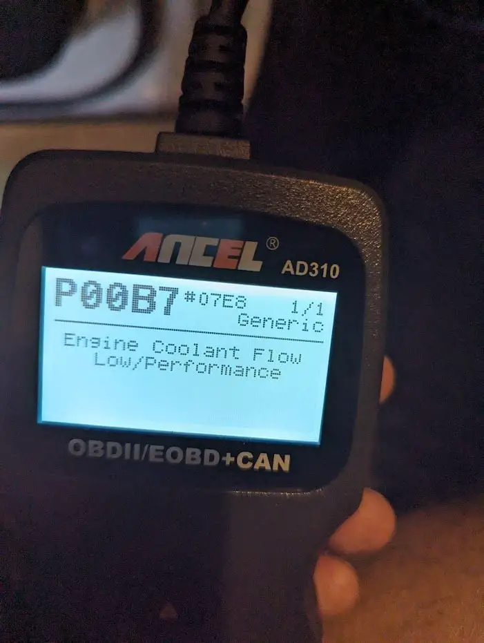
Your car’s PCM keeps a close eye on both sensors. If it sees a significant temperature difference (more than 68°F) between the radiator coolant temperature sensor (RCT) and the engine coolant temperature sensor (ECT), the P00B7 would be logged.
To prevent the engine from getting too hot, the PCM might kick the radiator fan(s) into high gear. This mechanism helps cool things down and prevents overheating. Code P00B7 can be encountered in various vehicle brands and models, including Chevrolet, GMC, Buick, Cadillac, and other manufacturers.
How Serious is the P00B7 Code?
The severity of code P00B7 falls into the moderate category. While it doesn’t represent an immediate danger like some other codes, it does require attention. Continuing to drive with this code present is generally not recommended. A restricted coolant flow can lead to overheating, which, if left unchecked, may cause engine damage. Overheating can also compromise your vehicle’s performance and fuel efficiency.
It’s advisable to address code P00B7 promptly. Have your vehicle inspected by a qualified mechanic to determine the exact cause. Timely maintenance can prevent more extensive and costly issues down the road, ensuring your vehicle operates efficiently and reliably.
What are the Symptoms of the P00B7 Code?
Here are some common symptoms that come along with the P00B7 code:
- Illuminated Check Engine Light
- Engine running rough
- Poor fuel economy
- Engine overheating
Read more: P0118: Engine Coolant Temperature Sensor Circuit High Input
What are the Causes of the P00B7 Code?
Now, let’s go through the potential causes of the P00B7 code:
- Wiring or connector problems in the thermostat circuit
- Low coolant level
- Bad water pump
- Damaged thermostats
- Malfunctioning ECT sensor
- Defective RCT sensor
- Faulty PCM/ECM
How To Diagnose and Repair P00B7 Code?
Diagnostic Tools and Essential Parts
When dealing with the P00B7 code, having the right tools and parts on hand is crucial. Here’s what you’ll need:
- OBD-II scanner
- Multimeter
- Coolant
- Thermostat replacement kit
- Wiring repair kit
- ECT sensor
- RCT sensor
Step-by-Step Guide
- OBD-II Code Retrieval:
Begin by using an OBD-II scanner to confirm the P00B7 code and assess any accompanying codes. - Wiring and connectors checking:
Inspect the PCM/ECM power relay for signs of damage or wear. If it’s faulty, replace it.
- Coolant level inspection:
Verify the coolant level is adequate. Top it up if it’s low.
- ECT and RCT Testing:
- Make sure the car’s ignition is off and unplug the sensors.
- Using a multimeter to check the resistance of each sensor.
- Compare the results to your car’s repair manual specs.
- If it’s not within the range, consider replacing the sensors.
- Checking the Thermostat
- Locate the thermostat housing on your vehicle’s engine.
- Remove the thermostat and inspect it for any signs of wear, such as rust or corrosion.
- Replace the thermostat if it shows signs of damage.
- PCM/ECM Testing (if needed):
- If the issue persists after addressing the above steps, consult a professional mechanic or auto technician to perform a diagnostic check on the PCM/ECM.
- They will use specialized tools to diagnose and potentially reprogram the PCM/ECM, if required.
- Clearing the code:
Clear the code and test drive.
Special Notes
If you have a Chevrolet or Cadillac vehicle, please check for this Technical Service Bulletin (TSB) (PIE0266) to see if they include your model or not. Similarly, Vauxhall Meriva (2011-2012) owners should look for this TSB. These TSBs often contain valuable information regarding known issues and solutions.
Keep in mind that the exact procedure may vary depending on the type of sensors and thermostats in your specific vehicle model, so it’s essential to consult your vehicle’s repair manual for precise testing instructions and specifications.
Read more: P0128 – Coolant thermostat
DIY Repair Level and Estimated Costs
This repair falls into the intermediate DIY category. While some experienced home mechanics may tackle it, others may prefer consulting a professional, especially when dealing with the PCM/ECM.
Take a look at this rough estimate for P00B7 solutions:
| Repair Task | Estimated Cost |
| Wiring and connector repair | $50 – $150 |
| ECT sensor replacement | $200 – $400 |
| RCT sensor replacement | $200 – $400 |
| Water pump replacement | $400 – $600 |
| Thermostat replacement | $150 -$300 |
| PCM/ECM replacement (rarely) | $500 – $1500 |
Please note that the estimated costs provided are approximate. For precise repair costs, we recommend consulting a certified mechanic or dealership. They can provide an accurate quote based on your vehicle’s make, model, and the extent of the required repairs.
Conclusion
Now that you have a clearer understanding of code P00B7 and its implications for your vehicle’s cooling system, you’re better prepared to address this issue confidently. By taking prompt action, you can ensure your engine stays within the suitable temperature range, keeping your car running smoothly.
If you found this article helpful, consider sharing it with other car owners who drive different makes and models, as the P00B7 isn’t exclusive to any particular brand.
Have you ever encountered the P00B7 code, or do you have additional insights or tips to share with the community? Feel free to drop a comment below. Your experiences and advice can be invaluable to others facing similar automotive issues.
Reference Sources
TechTips, Opel Meriva B – Fault Code P00B7.
P015B Code: Understanding Oxygen Sensor Issues
P015B Code: Understanding Oxygen Sensor Issues
Your vehicle suddenly experienced issues; you connected a diagnostic tool and discovered the P015B code. What happened to your car?
Well, P015B specifically refers to a delayed response from the Oxygen sensor (O2 sensor) in Bank 1, Sensor 1, resulting in a transition from a rich to a lean air-fuel mixture. This can have an impact on the vehicle’s performance and fuel efficiency.
Keep reading if you’re curious to learn more about the P015B code, its implications, and how to address it. We’ll guide you through the process, providing expert insights and practical solutions to help you get your vehicle back on track.
Let’s dive in!
P015B Code: Quick Overview
Here’s a glance at the key details regarding the P015B code!
- Definition: O2 sensor Delayed Response – Lean to Rich (Bank 1, Sensor 1)
- Severity: Medium
- DIY Skill Level: Intermediate
- Continue To Drive?: No
- Estimated Repair Cost: $50 – $300
What Does the P015B Code Mean?
The P015B code indicates a specific issue with the O2 sensor in Bank 1, Sensor 1, of the vehicle’s exhaust system. This sensor is responsible for measuring the oxygen content in the exhaust gases and providing feedback to the engine control module (ECM) to ensure optimal air-fuel mixture for combustion.
The code is commonly triggered in various car models, including Chevy (especially Cruze, Silverado, Tahoe, and Malibu), GMC, Nissan, Subaru, and Buick. However, it’s important to note that the P015B code can also be present in other vehicles as it’s a generic OBD-II code.
To understand why the P015B code is triggered, let’s take a closer look at the systems and components involved. In modern vehicles, the exhaust system consists of multiple O2 sensors strategically placed before and after the catalytic converter. The O2 sensor in Bank 1, Sensor 1, is located on the side of the engine where cylinder 1 is present.
The O2 sensor works with the ECM and other engine sensors to maintain the proper air-fuel ratio. It continuously measures the oxygen content in the exhaust gases before they enter the catalytic converter. Based on this measurement, the ECM adjusts the fuel delivery to ensure efficient combustion. When the O2 sensor in Bank 1, Sensor 1, experiences a delayed response in transitioning from a rich (more fuel) to a lean (less fuel) air-fuel mixture, it triggers the P015B code.
Read more: P0151 Code: Understanding O2 Sensor Circuit Low Voltage
How Serious is the P015B Code?
The P015B code could affect the engine’s air-fuel mixture and, consequently, its performance and fuel efficiency. Therefore, this diagnostic trouble code (DTC) should be considered a medium-to-high severity.
While the P015B code itself may not cause immediate or severe damage to the vehicle, it’s important not to ignore it. Continuously driving with the code unresolved can lead to long-term issues, such as reduced fuel economy, engine misfires, or damage to the catalytic converter.
Therefore, we strongly advise against continuing to drive and ignoring the P015B code. It’s best to address the underlying cause promptly to prevent any potential complications. By diagnosing and repairing the issue, you can restore the proper functioning of the O2 sensor and ensure optimal engine performance.
Read more: P0171: System Too Lean (Bank 1)
Signs of the P015B Code
When your vehicle encounters the P015B code, it may exhibit certain symptoms that indicate the presence of this issue.
- Illuminated Check Engine Light (CEL) or Service Engine Soon (SES) Light
- Poor fuel economy
- Reduced engine performance
- Increased emissions
- Rough idling and engine misfiring (less common)
Read more: P0172: System Too Rich (Bank 1)
Potential Triggers of the P015B Code
The P015B code can be triggered by various underlying causes.
- Malfunctioning O2 sensor
- Wiring or connector issues
- Exhaust leaks
- Fuel system problems
- Faulty ECM
How To Effectively Diagnose and Fix The Code P015B?
Take a look at this section, which provides step-by-step instructions for diagnosing and repairing the P2006 code.
Essential Tools and Parts
To diagnose and repair the P015B code, you will need the following tools and parts:
- OBD-II scanner or code reader
- Multimeter
- Oxygen sensor socket or wrench
- Wire crimping tool
- Replacement O2 sensor (if necessary)
Step-by-step procedure
Step 1: Use the OBD-II scanner or code reader to retrieve the P015B and any accompanying codes.
Step 2: Inspect the wiring and connectors associated with the O2 sensor. Look for any visible damage, corrosion, or loose connections. Repair/ replace any damaged components as necessary.
Step 3: Test the O2 sensor using a multimeter to measure its voltage output and response time. If the O2 sensor fails the tests, it may need to be replaced. Refer to the vehicle’s manual or online resources for the specific replacement procedure.
Step 4: Inspect the exhaust system for any leaks or damage. Check for signs of leakage, such as sooty deposits or unusual noises. Repair any identified exhaust leaks promptly.
Step 5: Examine the fuel system components, including the fuel injectors, fuel pressure regulator, and fuel lines, for any issues. Look for clogs, leaks, or improper fuel pressure. Address any fuel system problems found during the inspection.
Step 6: Clear the codes using the OBD-II scanner or code reader. This will reset the vehicle’s ECM. Perform a test drive to monitor the vehicle’s performance and confirm if the issue has been resolved.
Notes and tips:
- The location of the O2 sensor may vary depending on the car model. For example, in a Chevy Cruze, the Bank 1 Sensor 1 is located in the exhaust manifold, while in a Nissan Altima, it is found in the front exhaust pipe.
- If the code still exists, after all, the ECM may be faulty. However, diagnosing and fixing ECM issues usually requires special tools and expertise. Consult a professional mechanic or authorized service center for further diagnosis and ECM-related repairs if needed.
DIY Repair Level and Estimated Costs
The diagnosis and repair of the P015B code can be considered a moderate-level DIY repair. It requires some technical knowledge and the use of specialized tools. If you’re unsure or uncomfortable performing the tasks, you should seek assistance from an expert or a qualified mechanic.
The estimated cost for the repair tasks associated with the P015B code can vary depending on factors such as the vehicle model, the need for parts replacement, and the labor rates in your area. Here is a breakdown of estimated costs for common repair tasks associated with addressing the P015B code.
| Repair Task | Estimated Cost |
| Wiring or connector repair/replacement | $50 – $200 |
| Replacement O2 sensor | $50 – $200 |
| Exhaust system repair | $200 – $1000 |
| Fuel system repair | $150 – $800 |
It’s essential to consult with a mechanic or obtain accurate cost estimates from local repair shops to better understand the specific costs involved in resolving the P015B code for your particular vehicle.
Wrapping Up
Now that you understand the P015B code and its significance in your vehicle, you’re ready to tackle this frustrating issue confidently. We hope our comprehensive guide has empowered you to effectively address the code and its causes. With this knowledge, you can approach the P015B code with confidence, knowing you have the tools to deal with it.
If you found this article helpful, please share it with fellow car enthusiasts and leave a comment below to share your experience or ask questions. For a complete list of OBD codes, use our user-friendly OBD Code list generator or try our OBD code lookup tool for specific DTCs.
Stay proactive for smoother driving!
Reference Sources
Wikipedia, Air-fuel ratio.
Autoscope, What Are The Differences Between Lean And Rich Mixtures In An Internal Combustion Engine?.
P0325 – Knock sensor 1 circuit
P0325 – Knock sensor 1 circuit
The P0325 code relates to the knock sensor on the bank 1 side of your car’s engine. It basically tells you it isn’t sending the right signals to the computer. There are a lot of reasons this could be happening, from bad wiring to a faulty sensor.
P0325 is a generic powertrain code that applies to a wide range of vehicle types. Having said that, it’s seen more often on certain cars than others. It’s more common in Asian cars than those made in the United States or Europe and is most common on Hondas, Nissans, and Toyotas.
You won’t likely experience any drivability issues when the P0325 code is active, but that doesn’t mean you can ignore it. Read on below to learn how to diagnose and repair this knock sensor trouble code before it leads to further problems.
P0325 code definition
P0325 code definition (generic): Knock sensor circuit malfunction (bank 1)
P0325 Honda code definition: Knock sensor circuit malfunction
P0325 Hyundai code definition: Knock sensor circuit malfunction
P0325 Nissan code definition: Knock sensor circuit malfunction
P0325 Toyota code definition: Knock sensor circuit malfunction
What does P0325 mean?
The knock sensor in your engine is there to tell you when the air/fuel mixture isn’t combusting properly. It detects explosions, which are called knocks, because of the noise they cause. When knocks happen, the engine doesn’t get as much power. If these happen for too long, it can cause engine damage.
The information sent to the computer from the knock sensor allows it to make adjustments. It may change the timing or otherwise tune the engine to prevent the knocks. You’ll find the knock sensor bolted or threaded into the engine block.
When the engine computer isn’t receiving the right information from the knock sensor, it triggers the P0325 trouble code. This code specifically refers to the knock sensor on bank 1 of the engine. Bank 1 is the side that includes cylinder 1.
What are the symptoms of the P0325 code?
There are not typically any drivability symptoms with the P0325 trouble code. The most common symptoms are:
- Activation of the check engine light
- Reduced engine power
If there are engine knocks occurring as well as damage to the knock sensor, you may notice the following symptoms:
- Hesitation from the engine
- Audible pinging from the engine, especially while accelerating
- Reduced fuel economy
What are the causes of P0325?
- Faulty knock sensor,
- Shorted or faulty wiring in the knock sensor circuit,
- Shorts or faults in the wiring harness,
- Faulty or loose electrical connections,
- Faults with engine coolant system,
- Engine running too lean,
- Failed PCM or ECU.
How serious is the P0325 code?
The P0325 trouble code is of relatively low severity. You won’t notice any drivability symptoms in most cases and can drive your car safely until you can repair it. However, it would be best if you fixed it quickly so you can be notified of knocking problems, which can damage your engine.
How to diagnose the P0325 code
Tools you’ll need:

Method:
- Check your vehicle’s manual for any specific troubleshooting tips related to the knock sensor. You can also check if there are any technical service bulletins out related to this trouble code. The repair for P0325 is often vehicle-specific. Follow any manufacturer-specific instructions you find before proceeding with the generic diagnostic below.
- Use your OBD2 scanner to check for any other codes. You may see other codes related to the knock sensor, such as P0330. If you see codes related to other sensors, such as the MAF sensor or oxygen sensors, this likely points to a wiring problem.
- Read the freeze frame data related to the knock sensor. Check the conditions that were present when the code was set, which can help you make a complete diagnosis.
- Clear the codes and test drive your vehicle, attempting to replicate the conditions of the failure.
- Verify that the knock sensor is sending a signal to the powertrain control module. If it’s not, use the OBD2 scanner to check the readings from the coolant temperature sensor.
- Visually inspect the wires around the knock sensor and wiring harness. Replace any wires that are damaged or corroded and ensure all the connections are secure.
Common mistakes to avoid while diagnosing the P0325 code
Many people replace the knock sensor before checking the wiring or looking for issues with the coolant system. Make sure you conduct a thorough diagnosis before replacing any components.
What should you do to fix the code P0325?
After each step of your repairs, clear all the trouble codes and test drive your vehicle to see if the code comes back. Since there are rarely drivability issues with this code, your OBD2 scanner will be crucial in discovering if you’ve fixed the problem.
- Replace any damaged wires you found during your diagnosis.
- If you detected any issues with the coolant temperature readings, replace the temperature sensor. Incorrect temperature readings can lead to overheating and other serious engine issues.
- If you’re certain there are no damaged wires or missing connections in your engine, replace the knock sensor and the knock harness.
- Should the P0325 code still not clear, take your car to a mechanic for further diagnosis. In rare instances, this code could indicate a problem with your electrical connections or the engine computer.
Tips to avoid P0325 in the future
An improperly-installed knock sensor is the most common cause of a P0325 code. Wires that aren’t firmly connected could be shaken loose over time by the vibration of the engine. Damaged or broken wires will also often trigger diagnostic trouble codes—not only P0325 but a host of codes related to sensors throughout your engine.
Take the extra time to check all the wires whenever you install or repair something in your engine. Check that the connections are secure and that the wires are clear of things that could cause damage or shorts.
Read more: P0010 Code: Meaning, Symptoms, Causes, Diagnostics, and Fixes
C0035 Code: Understanding Wheel Speed Sensor Issues
C0035 Code: Understanding Wheel Speed Sensor Issues
Encountering the C0035 code? Don’t worry – we’re here to help. The C0035 code is a common ABS fault code that relates to wheel speed sensor issues in vehicles.
In this comprehensive article, we’ll be your trusted companion as we explore the ins and outs of the C0035 code. From identifying symptoms to uncovering causes and offering practical solutions, we’ve got you covered.
So, let’s dive in!
C0035 OBD2 Code: A Quick Overview
Take a quick look at the key information of the C0035 code below!
- Definition: Right Front Wheel Speed Sensor Supply (subfault)/ Left Front Wheel Speed Sensor
- Severity: High
- DIY Skill Level: Intermediate
- Continue To Drive?: No
- Estimated Repair Cost: $30 – $200
What Does The C0035 Code Indicate?
The C0035 code indicates a fault related to the wheel speed sensor in the vehicle’s anti-lock brake system (ABS). Although this is a generic fault code, which can happen on all cars equipped with the OBD2 system, it most frequently occurs in GM vehicles, including popular models like Chevy Silverado, Impala, and Equinox.
The wheel speed sensors play a vital role in the ABS system. Each wheel speed sensor generates a digital square wave signal as the front wheels spin. The electronic brake control module (EBCM) relies on the frequency of these signals to determine the speed of each wheel. When the EBCM detects an issue with the front wheel speed sensor or its circuit, such as a missing signal or significantly low supply voltage compared to the monitored ignition voltage, it logs the C0035 code.
Special Note:
There might be variations in code definitions depending on the car model. When researching information about the C0035 code, you might come across these two definitions: “Right Front Wheel Speed Sensor Supply (subfault)” and “Left Front Wheel Speed Sensor.”
In certain GM vehicles, the code is commonly referred to as “Right Front Wheel Speed Sensor Supply (subfault). The SAE organization also uses this definition for the C0035 code. While most cars will display the code in reference to the right front wheel, there are a few exceptions where it may pertain to the left wheel instead.
To accurately diagnose the problem in your specific vehicle, it’s crucial to not only consider the diagnostic code you receive but also carefully review the short description of the problem that your car is experiencing.
C0035 Severity: Don’t Ignore It!
The C0035 code should be considered a high-severity issue. Ignoring this code can adversely affect your vehicle’s performance and safety. It is important to address the issue promptly to avoid potential risks and ensure optimal operation of your vehicle’s braking system.
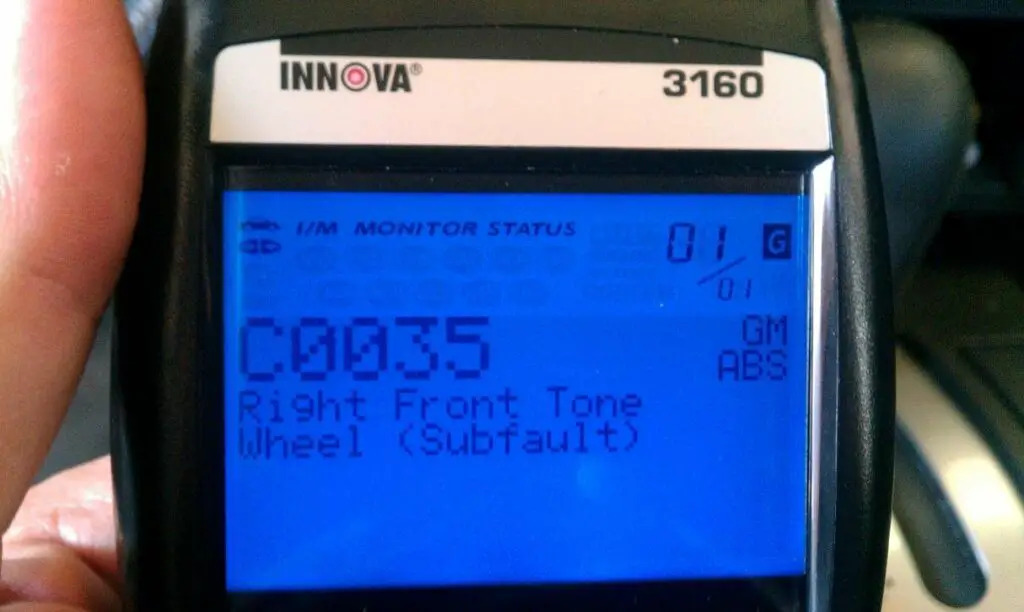
(Image credit: 3800Pro Forum)
We advise against continuing to drive with the C0035 code. It’s recommended to have your vehicle inspected and repaired by a qualified mechanic who can diagnose the specific cause of the code and perform the necessary repairs.
Signs Of The C0035 Code To Look Out For
When the C0035 code is present in your vehicle, you may experience several symptoms, such as:
- Illuminated dashboard warning lights: Check Engine Light, ABS warning light, traction control light may also be illuminated
- Inoperative or overactive ABS, traction control, and stability control systems
- Issues with the vehicle speed displayed on the dashboard
- Brake pedal shocks or abnormal feedback
Read more: GM OBD2 Codes List For FREE Download
Common Triggers Of The C0035 Code
The C0035 code can be triggered by various causes related to the wheel speed sensor and the ABS system, including:
- Faulty or malfunctioning wheel speed sensor
- Damaged or disconnected sensor wires
- Poor connection or corrosion in the sensor circuit
- Sensor reluctor wheel damage
- Issues with the ABS module, including outdated software or programming
Read more: U0415 Code – Invalid Data Received From ABS Control
Step-by-Step Guide: Diagnosing And Fixing The C0035 Code
Check the following sections as we guide you through diagnosing and repairing the C0035 code.
Essential Tools And Parts
- OBD-II scanner or diagnostic tool
- Wheel speed sensor (if replacement is necessary)
- Socket set and wrenches
- Electrical contact cleaner
- Wire brush or abrasive pad
- Dielectric grease
- Jack and jack stands (if required)
Step-by-Step Procedure
Step 1: Retrieve DTCs and identify the affected wheel speed sensor
Connect the OBD-II scanner or diagnostic tool to retrieve the specific trouble codes. Take note of any accompanying codes that may be present. Address these codes first before proceeding with the C0035 diagnosis and repair process.
The OBD-II scanner or diagnostic tool should provide information about which wheel speed sensor is causing the code C0035. Typically, the code will specify the specific wheel or location, such as the front left (FL) or front right (FR) wheel speed sensor.
Step 2: Inspect the sensor wires and connectors
Inspect the sensor wires and connectors for visible damage, such as cuts or loose connections. Clean the connectors using an electrical contact cleaner to remove any corrosion or dirt.
Step 3: Check the sensor reluctor wheel
Check the sensor reluctor wheel for damage or debris. Clean it using a wire brush or abrasive pad if necessary.
Step 4: Test the wheel speed sensor resistance
Test the resistance of the wheel speed sensor using a multimeter. Compare the resistance readings to the manufacturer’s specifications to determine if the sensor is faulty.
Step 5: Replace the faulty wheel speed sensor
If the sensor is determined to be faulty, replace it with a new one. Ensure proper installation by connecting the electrical connector and securely fastening the sensor.
Step 6: Clear codes and test drive
Clear the trouble codes using the OBD-II scanner and test drive the vehicle to ensure the code does not reappear.
Note:
- The exact location of the wheel speed sensor can vary depending on your vehicle’s specific model. For example, in many Chevrolet vehicles, the wheel speed sensors are typically located near the wheel hub or inside the wheel bearing assembly. While in Ford F-150 trucks, these sensors are typically located on each wheel hub assembly, near the brake rotor or axle.
- It’s recommended to consult a service manual or seek professional assistance for detailed instructions specific to your vehicle’s make and model.
- Additionally, taking necessary safety precautions, such as wearing gloves and working in a well-ventilated area, is essential during the repair process.
DIY Repair Level And Estimated Costs
DIY enthusiasts with intermediate mechanical skills can attempt the wheel speed sensor diagnostic and repair process. It involves basic electrical troubleshooting, visual inspection, and potential component replacement.
Diagnosing and cleaning the sensor connectors or reluctor wheel is relatively easy and can be done by most people. However, it’s best to consult an expert mechanic if sensor replacement or advanced troubleshooting is needed.
Below is a general overview of the estimated costs for common repair tasks related to the wheel speed sensor issue:
| Repair Task | Cost Range |
| Diagnostic fee | $50 – $150 |
| Wiring Repair | $50 – $200 |
| Wheel speed sensor replacement | $50-$150 (including labor) |
Remember, these costs are approximate and can vary depending on factors such as vehicle make and model, location, and labor rates. It’s always recommended to obtain an accurate estimate from a trusted mechanic or repair shop.
Wrapping Up
So, to wrap things up, remember that understanding and addressing the C0035 code is key to keeping your ABS system performing at its best.
But hey, we get it – not everyone is a car repair expert. That’s why it’s always a smart move to turn to a qualified mechanic when you need that extra expertise.
If you find this guide helpful, don’t keep it to yourself! Share it with others who may benefit from it. Also, leave your questions or insights about the C0035 code in the comments below.
Wishing you safe and enjoyable driving experiences ahead!
Reference Sources
- Tire Review, Wheel Speed Sensor Diagnostics for Meters and Scopes.
- MyCarDoesWhat, Anti-Lock Braking System.
P1157 Honda: Troubleshooting Air/Fuel Sensor Issues
P1157 Honda: Troubleshooting Air/Fuel Sensor Issues
If you’ve come across the P1157 Honda diagnostic trouble code, you’re not alone. This perplexing code has left many Honda owners searching for answers.
In this guide, we’ll explore the meaning, severity, symptoms, causes, and diagnosis of P1157 Honda. With our expertise in Honda vehicles, we’ll help you navigate through this challenge and find effective fixes.
So, let’s get started!
P1157 Honda Code: Quick Summary
Here’s a brief overview of the essential details regarding the P1157 Honda code:
- Definition: Air/Fuel Ratio (A/F) Sensor (Sensor 1) Circuit High Voltage
- Severity: Medium
- DIY Skill Level: Intermediate
- Continue To Drive?: Yes (Short-term)
- Estimated Repair Cost: $50-$200
Understanding The P1157 Code In Your Honda
The P1157 code is a common issue reported by owners of Honda vehicles, particularly the Accord, CRV, Element, and Civic models. This code indicates a potential problem with the A/F (Air/Fuel) sensor, specifically Sensor 1.
The A/F sensor plays a crucial role in measuring the oxygen content in the exhaust gas. It consists of a sensor element with an embedded heater. When activated, the heater warms up the sensor to enhance the detection of oxygen content, allowing for precise measurement. The current flowing through the heater is proportional to the oxygen content, which helps determine the air/fuel ratio.
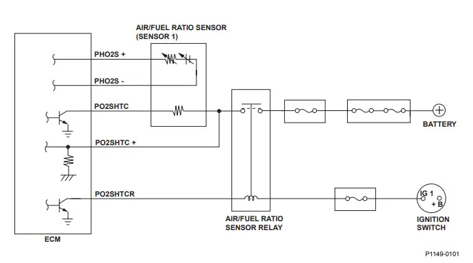
In normal operation, the engine control module (ECM) compares the detected air/fuel ratio with the target air/fuel ratio. Based on this comparison, the ECM adjusts the fuel injection duration to maintain optimal combustion efficiency.
If the A/F sensor (Sensor 1) voltage is low, indicating a lean air/fuel ratio, the ECM issues a Rich command to increase the fuel mixture. Conversely, if the A/F sensor (Sensor 1) voltage is high, indicating a rich air/fuel ratio, the ECM issues a Lean command to reduce the fuel mixture.
The triggering of the P1157 Honda code occurs when the A/F sensor (Sensor 1) fails to activate its heater within a set time period while drawing power. The ECM detects this malfunction and stores the Diagnostic Trouble Code (DTC) P1157.
Read more: Honda OBD 2 Codes List [Generic + Manufacturer-specific]
How Serious Is The P1157 Honda?
When it comes to the severity of the P1157 Honda code, it is considered a moderate-level issue. While it may not pose an immediate threat to the safety or functionality of your Honda vehicle, it should still be addressed promptly.
In most cases, it is generally safe to continue driving your vehicle when you encounter the P1157 Honda code. However, it is important to address this code as soon as possible to prevent any potential issues with fuel combustion, fuel efficiency, or engine performance.
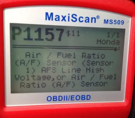
(Image credit: Drive Accord Forum)
To ensure your vehicle’s longevity and optimal functioning, it is advisable to have the underlying cause of the P1157 Honda code diagnosed and resolved promptly. By doing so, you can restore the proper operation of the A/F sensor system and maintain optimal fuel efficiency and engine performance.
Read more: P1009 Honda Code: VTC System Troubleshooting And Solutions
Common Signs Of P1157 Honda To Watch For
The P1157 Honda code typically presents with the following symptoms:
- Check Engine Light (CEL) illuminated
- Decreased fuel efficiency
- Engine runs rough or misfires
- Poor acceleration or lack of power
- Increased exhaust emissions
P1157 Honda Causes: What’s Behind The Code
Here are some common causes of the P1157 Honda code:
- Wiring damage or break in the A/F sensor (Sensor 1) circuit
- Faulty A/F sensor (Sensor 1)
- Defective ECM (connection issues or internal fault) – rarely
Diagnosis And Repair For P1157 Honda
In this section, we’ll provide you with a comprehensive guide to diagnose and repair the P1157 Honda code. We’ll cover the essential tools and parts required, a step-by-step procedure with helpful tips, as well as the level of DIY repair and estimated costs associated with resolving this code.
However, it’s important to note that if you’re unsure or uncomfortable with the repair process, it’s always advisable to seek assistance from a professional mechanic.
Essential Tools And Parts
To diagnose and repair the P1148 code, you may require the following tools and parts:
- OBD-II scanner
- Multimeter
- A/F sensor (Sensor 1) replacement (California-emission compliant)
- Wiring repair kit (if necessary)
- Socket set and wrenches
Step-by-Step Guide
- Connect the OBD-II scanner to retrieve the P1157 Honda code and any additional codes.
- Inspect the A/F sensor wires, wiring, and connectors for any visible damage, such as frayed wires or loose connections. Repair or replace the damaged wiring using a wiring repair kit.
- Use a multimeter to test the voltage and resistance of the A/F sensor and its heater circuit. Compare the readings to the manufacturer’s specifications.
- If the readings are abnormal and the wiring has been addressed, replace the A/F sensor (Sensor 1) with a compatible replacement part. Ensure that it meets the necessary specifications for your vehicle, especially if it requires California-emission compliance.
- Inspect the ECM connections for any loose, corroded, or damaged pins. Ensure that the ECM is properly connected. Address any connection issues detected by cleaning the connections, repairing any damaged pins, or replacing the connector if necessary.
- If the problem still persists, consider the possibility of an ECM internal fault. In this case, perform the following steps:
- Perform an ECM idle learn procedure as the vehicle’s service manual recommends.
- Check if the ECM has the latest software version. If not, update the ECM with the latest software available.
- If updating the ECM software doesn’t resolve the issue, you may need to substitute the ECM with a known-good ECM for testing purposes.
- Clear the codes using the OBD-II scanner and test-drive the vehicle to verify if the issue is resolved.
Notes:
- If your car has California emissions, use the California version of the sensor. The PCM is programmed to read the California-emission sensor specifically. The labor required for sensor replacement should be the same.
- Always use OEM sensors on Honda vehicles, as non-OEM sensors may not work properly with the ECM, even if they are functioning correctly.
- The exact location of the A/F sensor (Sensor 1) in a Honda vehicle can vary depending on the specific model and engine configuration. However, as a general guideline, it is typically located in the exhaust pipe near the bend from the engine to the catalytic converter.
DIY Repair Level And Estimated Costs
The repair procedure for the P1157 Honda code falls under an intermediate DIY level. While enthusiasts with moderate mechanical skills can tackle it, exercising caution and following the steps precisely is important. For those who prefer professional assistance, don’t hesitate to consult a skilled mechanic.
Let’s review the diagnostic and repair tasks involved in addressing the P1157 Honda code. Here’s a breakdown:
| Repair Tasks | Estimated Costs |
| Wiring repair | $20 – $50 |
| A/F sensor replacement | $100 – $200 (parts and labor) |
| ECM update | $50 – $150 |
| ECM replacement | $500 – 1,000 (parts and labor) |
Remember, these are general estimates, and actual costs may differ. It’s advisable to consult local professionals and parts suppliers for the most accurate pricing information in your specific area.
P1157 Honda Infographic
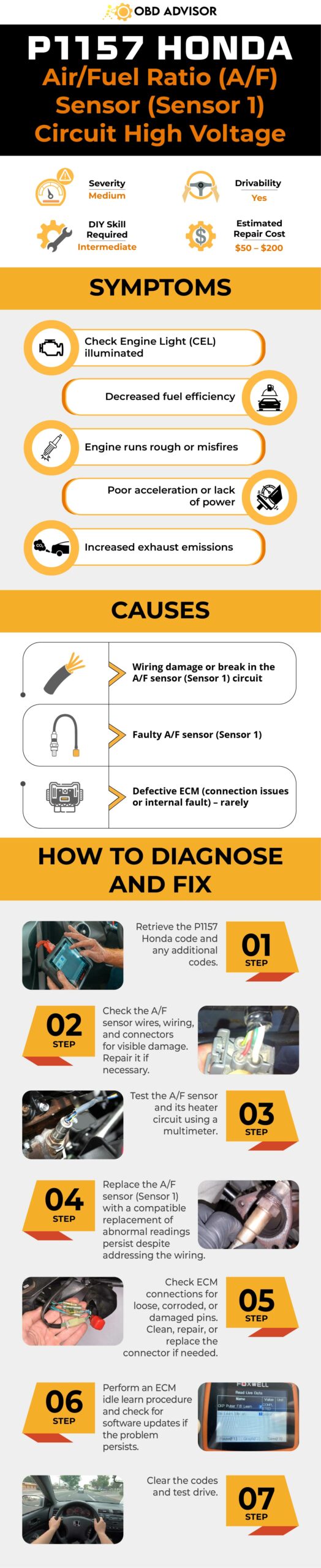
Wrapping Up
Before we wrap up, let’s ensure your Honda runs smoothly with the P1157 code addressed.
If you have any more questions or need further assistance, feel free to ask.
Remember, you don’t have to tackle it alone – professional mechanics are always there to lend a hand.
Stay safe on the road and enjoy your Honda’s optimal performance!
Reference Sources
- Gershon (uCoz), Service Bulletin 03-020.
- Drive Accord Honda Forum, P1157 – New o2 sensor didn’t fix it.
- CR-V Owners Club Forum, P1157 Cannot resolve.
- Honda Accord Forum, P1157 code 2003 Accord LX.
P1148 Nissan Code: Closed-loop Control Issues & Solutions
P1148 Nissan Code: Closed-loop Control Issues & Solutions
If you own a Nissan and are dealing with the P1148 code, you’ve come to the right place.
This article is your go-to resource for all things P1148 Nissan code. I’m here to guide you through it all, sharing my expertise and experience to help you understand what this code means and how to fix it like a pro.
So, let’s dive in!
P1148 Nissan: A Quick Overview
Let’s take a quick look at the key details of the P1168 Nissan code in the summary box below!
- Definition: Closed Loop Control Function Bank 1
- Severity: Medium
- DIY Skill Level: Intermediate
- Continue To Drive?: Yes
- Estimated Repair Cost: $50 – $200
Inside The P1148 Nissan Code: What Does It Mean?
The P1148 code in Nissan vehicles indicates a problem with the closed-loop control function of the A/F sensor or the conventional Heated Oxygen Sensor (HO2S) circuit for Bank 1. This code is triggered by the engine control module (ECM) when it detects that the closed-loop control function is not operating properly under certain driving conditions.
Note: Throughout this guide, when we refer to “sensor,” we mean both the A/F sensor and HO2S sensor, as they share similarities and can cause the P1148 code.
(Image credit: Pathfinder Talk forum)
To comprehend the P1148 code, it’s important to clearly understand the systems and components involved. The A/F sensor plays a vital role in measuring the oxygen content within the exhaust gases. This crucial data is then utilized by the ECM to finely adjust the air-fuel mixture, optimizing combustion efficiency for better performance.
This code is commonly found in models such as Altima, Pathfinder, Frontier, Titan, Murano, Sentra, Xterra, Maxima, Rogue, 350z, Armada, Quest, Versa, and Juke. It’s worth noting that this code often accompanies codes P0041 and P0031, both of which relate to O2 sensor concerns.
Read more: P1168 Nissan Code – a similar code to the P1148 code, but P1168 is specific to Bank 2 in Nissan vehicles.
How Serious Is The P1148 Nissan Code?
The severity level of the P1148 Nissan code can be considered moderate. While it does not pose immediate dangers or render the vehicle undrivable, addressing the problem as soon as possible is advisable.
Although you may be able to continue driving with the P1148 code for a limited period, it’s important to address the underlying issue. Prolonged driving without resolving the problem can decrease fuel efficiency and potentially impact engine performance.
To avoid further complications and potential damage, diagnose and repair the problem promptly. Taking proactive measures will help prevent more severe issues from arising down the road.
Warning Signs Of P1148 Nissan
The following are common symptoms associated with the P1148 code:
- Check Engine Light (CEL) and/or Service Engine Soon (SES) light illuminated
- Decreased engine performance
- Reduced fuel efficiency
- Rough idle
- Irregular exhaust emissions
Causes Of The P1148 Nissan Code
The P1148 code can be caused by various factors, including:
- Open or shorted circuit in the A/F sensor or HO2S circuit for Bank 1
- Malfunctioning A/F sensor or HO2S sensor for Bank 1
- Faulty A/F sensor or HO2S sensor heater for Bank 1
Read more: Nissan Trouble Codes: Comprehensive List For OBD1/OBD2 Codes
P1148 Nissan Code: DIY Diagnosis And Repair
If you’ve encountered the P1148 code in your Nissan vehicle, you can attempt a DIY diagnosis and repair before seeking professional assistance. Follow the step-by-step guide below:
Essential Tools And Parts
To diagnose and repair the P1148 code, you may require the following tools and parts:
- OBD-II scanner
- Multimeter
- Socket set
- Oxygen sensor socket (if needed)
- Replacement sensor (A/F or HO2S sensor) (if necessary)
Your Step-by-Step Guide To Tackle P1148
- Inspect the wiring and connectors associated with the sensor for Bank 1. Look for any signs of damage, loose connections, or corrosion. Ensure that the wiring is securely connected and free from any obstructions.
- Test the voltage and resistance of the sensor using a multimeter. This will help determine if the sensor is functioning within the specified range. Consult the vehicle’s service manual for the appropriate voltage and resistance values.
- If needed, remove the sensor using an appropriate oxygen sensor socket and replace it with a new one.
- Clear the code and perform a system test to ensure that you have resolved the issue.
Quick Tips:
- Apply anti-seize compound to the sensor threads before installation to facilitate future removal.
- Common location of A/F sensor for Bank 1 in Nissan vehicles: Typically, it’s bolted onto the exhaust manifold or front section of the exhaust pipe. Check the service manual or consult a Nissan dealership for exact location details.
Notes: It’s important to consult the vehicle’s repair manual for specific instructions and diagrams related to your particular Nissan model.
DIY Repair Level And Estimated Costs
Diagnosing the P1148 code and inspecting the wiring and connectors can be performed by DIY enthusiasts with intermediate-level skills. However, replacing the sensor may require more advanced knowledge and tools. If you’re unsure or uncomfortable with the repair process, we recommend consulting a qualified mechanic.
The table below provides estimated costs for common repair tasks associated with the P1148 code in Nissan vehicles.
| Repair Task | Estimated Cost Range |
| Diagnosing the code | $50 – $150 |
| Wiring harness connectors and terminals | $50 – $100 |
| Inspecting wiring/connectors | $50 – $100 |
| Replacing sensors | $100 – $200 |
Please note that these estimated costs are only for reference purposes and can vary based on location, the specific vehicle model, and labor rates. We recommend consulting a qualified mechanic or obtaining a detailed quote to assess the cost accurately.
P1148 Nissan Infographic
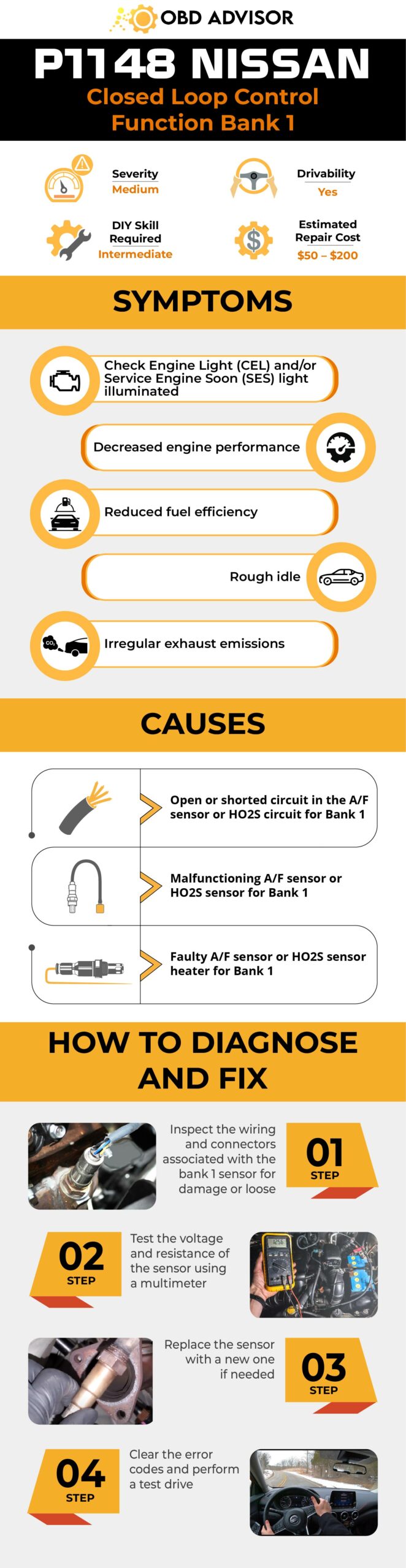
Final Thoughts
To wrap things up, taking on the P1148 code in your Nissan is entirely achievable.
Just make sure you have the right tools and follow the steps provided. By doing so, you’ll be able to address any issues with the A/F sensor and HO2S circuit for Bank 1, ultimately giving your engine a performance boost. You’ve got this!
Remember to stay cautious, consult the repair manual if needed, and consider professional help if unsure.
Share this knowledge with others and enjoy the journey of fixing your vehicle. Safe driving!
Reference Sources
- Tire Review Magazine, 2011 May 6, Fuel System Definitions and Diagnostic Trouble Codes.
- Automotive Manuals, 2007, Nissan Engine Control System Diagnosis Guide – page EC-393.
P1259 Honda Code: Resolving VTEC Issues in Your Vehicle
P1259 Honda Code: Resolving VTEC Issues in Your Vehicle
If you own a Honda vehicle and have encountered the P1259 code, it’s essential to understand its implications and take appropriate action. In this comprehensive guide, we’ll provide you with the knowledge and steps needed to diagnose and resolve the P1259 code, ensuring optimal performance and longevity for your Honda engine.
From symptoms to diagnostic procedures, we’ll walk you through the process, empowering you to tackle this code with confidence.
So, let’s delve into the details of the P1259 code in Honda vehicles.
P1259 Honda Code: A Quick Overview
Take a look at the summary of the Honda P1259 code provided below!
- Definition: VTEC System Malfunction
- Severity: Medium
- DIY Skill Level: Intermediate
- Continue To Drive?: Yes
- Estimated Repair Cost: $20 – $200
What Does The P1259 Honda Code Mean?
P1259 code is a manufacturer-specific code that is specific to Honda and Acura vehicles. It relates to the VTEC (Variable Valve Timing and Lift Electronic Control) system, a unique technology Honda developed. Some Honda models usually encounter this code, including Accord, Civic, CR-V, Odyssey, Pilot, etc.
The VTEC system is designed to optimize engine performance by adjusting the valve timing and lift according to driving conditions. It operates by using two different camshaft profiles: one for low-speed operation and the other for high-speed performance. This allows the engine to deliver both efficient and powerful performance across a wide range of driving scenarios.
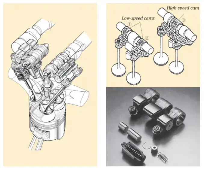
(Credit: global.honda)
The VTEC system in Honda engines engages at higher RPMs or when more power is needed. It uses oil pressure to adjust the camshaft lobes, optimizing valve lift and timing for improved efficiency and performance. This technology is a signature feature of Honda engines, offering benefits such as better fuel economy, increased torque, and overall enhanced performance.
However, when the VTEC system encounters a malfunction, the P1259 code is triggered. This typically indicates an issue with the VTEC oil pressure switch or the solenoid valve. These components play crucial roles in controlling the oil pressure and activating the VTEC mechanism.
Note:
- Honda has issued a Technical Service Bulletin (TSB) to help address the P1259 code in the 2001 Honda Accord models. The TSB suggests that a possible cause of the VTEC system malfunction and stored fault code is a low engine oil level. Before costly troubleshooting of the VTEC system, it is recommended to check the oil level and pressure. Ensuring proper oil supply and pressure may resolve the issue. If the problem persists or the oil level is adequate, consulting a qualified technician or visiting a Honda service center is advised for further diagnosis and repair.
- Typically, if the P1259 code is set below 4000 RPM, it indicates a potential wiring problem or a faulty VTEC pressure switch. However, when the code appears at 4000 RPM or higher, it is usually related to an oil-related issue.
How Severe Is The P1259 Code In Your Honda?
The severity level of the P1259 code in a Honda vehicle is generally considered to be moderate. While the vehicle may still be drivable with the P1259 code present, it is not recommended to ignore it. Therefore, we highly advise addressing the P1259 code promptly by diagnosing and repairing the vehicle.
The common symptoms associated with the P1259 code in Honda vehicles typically include:
- Check Engine Light (MIL) illumination
- Reduced engine performance
- Rough idling or stalling
- Decreased fuel efficiency
- Car shaking at idle
- Knocking or rattling sounds
- Reduced power output in VTEC mode, normal in non-VTEC mode
- Sluggish acceleration and difficulty downshifting in VTEC mode
Causes Of The P1259 Honda Code
The P1259 code in Honda vehicles can be caused by various factors, including:
- Low engine oil level or pressure
- Faulty VTEC oil pressure switch
- Malfunctioning VTEC solenoid valve
- Wiring or connector issues related to the VTEC system
- ECM (Engine Control Module) malfunction
Read more: P145C Honda Code: Expert Tips for Emission System Repairs
P1259 Honda Code: Diagnostic And Repair
In this section, we will provide essential tools and parts required, a step-by-step procedure for diagnosing and fixing the P1259 code, and discuss the level of DIY repair and estimated costs involved.
Essential Tools And Parts
To diagnose and repair the P1259 code in a Honda vehicle, you may need the following tools and parts (if required):
- OBD-II scanner or diagnostic tool
- Digital multimeter
- Engine oil dipstick
- Engine oil
- VTEC oil pressure switch
- VTEC solenoid valve
- Wiring diagram for the vehicle
Step-by-Step Procedure
- Code retrieval: Use an OBD-II scanner to retrieve the P1259 code and record any additional associated codes.
- Check engine oil level: Using the engine oil dipstick, check the oil level and ensure it falls within the recommended range. If it falls out of the range, performing an oil change is a must.
- Inspect wiring and connectors: Examine the wiring and connectors related to the VTEC system for any visible damage or loose connections. Repair or replace if necessary.
- Test VTEC oil pressure switch and VTEC solenoid valve: Utilize a digital multimeter to perform tests on the VTEC oil pressure switch and VTEC solenoid valve, ensuring they function correctly. Replace the parts if needed.
- Verify wiring connections and continuity: Refer to the vehicle’s wiring diagram to confirm the proper wiring connections and continuity for the VTEC system.
- Clear the P1259 code: Clear the trouble code and test drive to make sure the code will not reappear.
Note: It is crucial to adhere to the specific diagnostic procedures provided in the vehicle’s service manual for precise diagnosis and repair of the P1259 code.
Read more: Honda OBD2 Codes List [Generic + Manufacturer-specific]
DIY Repair Level And Estimated Costs
The level of DIY repair for the P1259 code will depend on your mechanical experience and access to tools. DIY enthusiasts can perform basic diagnostic steps, such as checking the engine oil level and inspecting wiring connections.
However, dealing with component replacements like the VTEC oil pressure switch or VTEC solenoid valve may require intermediate to advanced mechanical skills. If you’re unsure or uncomfortable with these tasks, we recommend seeking professional assistance.
The estimated costs for repairing the P1259 code can vary depending on the specific vehicle and the need for parts replacement. So, here is a rough breakdown of potential costs:
| Repair Task | Estimated Cost |
| Oil changing | $20 to $100 |
| VTEC oil pressure switch | $50 to $100 |
| VTEC solenoid valve | $100 to $200 |
Final Thoughts
Are you ready to tackle the P1259 code in your Honda vehicle? Well, with the knowledge you’ve gained, you can confidently diagnose and resolve this issue. Moreover, don’t keep this valuable information to yourself – share it with fellow Honda owners who may be facing similar challenges.
If you have any questions or success stories, we’re here to listen in the comments section below. Additionally, let’s keep our Honda engines running smoothly and efficiently. Drive with confidence and take care of your Honda!
Reference Sources
- Tech Tips Ireland, Honda Accord – Engine Light On Fault Code P1259 [PDF file]
- CarBrain, Unusual Car Noises That Might Ruin Your Budget
- Wikipedia, VTEC
P0442: Evaporative Emission System Leak Detected (small leak)
P0442: Evaporative Emission System Leak Detected (small leak)
If you’ve got the P0442 error code showing up on your OBD scanner, don’t worry, as it is easily fixable.
Here is a quick brief to let you know what you’re facing and what to expect.
- P0442 Definition: Evaporative Emission Control System Leak Detected (Small Leak).
- Code Type: Generic – P0442 indicates the same problem whether you’re having a Chevy, Ford, or Toyota, etc.
- Can I drive with the P0442 code? Yes. There is almost no danger to the driver.
- Easy to fix: Beginner to intermediate DIY skills.
- Cost: $10 – $20 (common)
Luckily, P0442 is safe to drive with!
But to avoid more harm to the car’s fuel economy and environment, let’s read on to know the possible causes, how to fix the issues, and the replacement costs.
What Does The P0442 Code Mean?
P0442 is an OBD-II generic code triggered when the engine control unit (ECU) detects a fuel vapor leak (small) somewhere in the evaporative emission control (EVAP) system.
The EVAP is a closed system, consisting of several valves, lines, and a charcoal canister.
Its purpose is to help prevent any fuel vapors from escaping into the atmosphere.
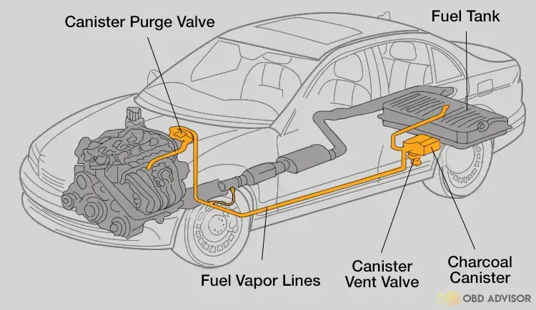
What happens if there is any leak in the EVAP system?
If there are any EVAP leaks, the fuel odor can enter the car’s interior and cause performance issues, triggering P0442.
You can continue to drive your car in the short run, but it’ll negatively affect the car’s mileage and the environment.
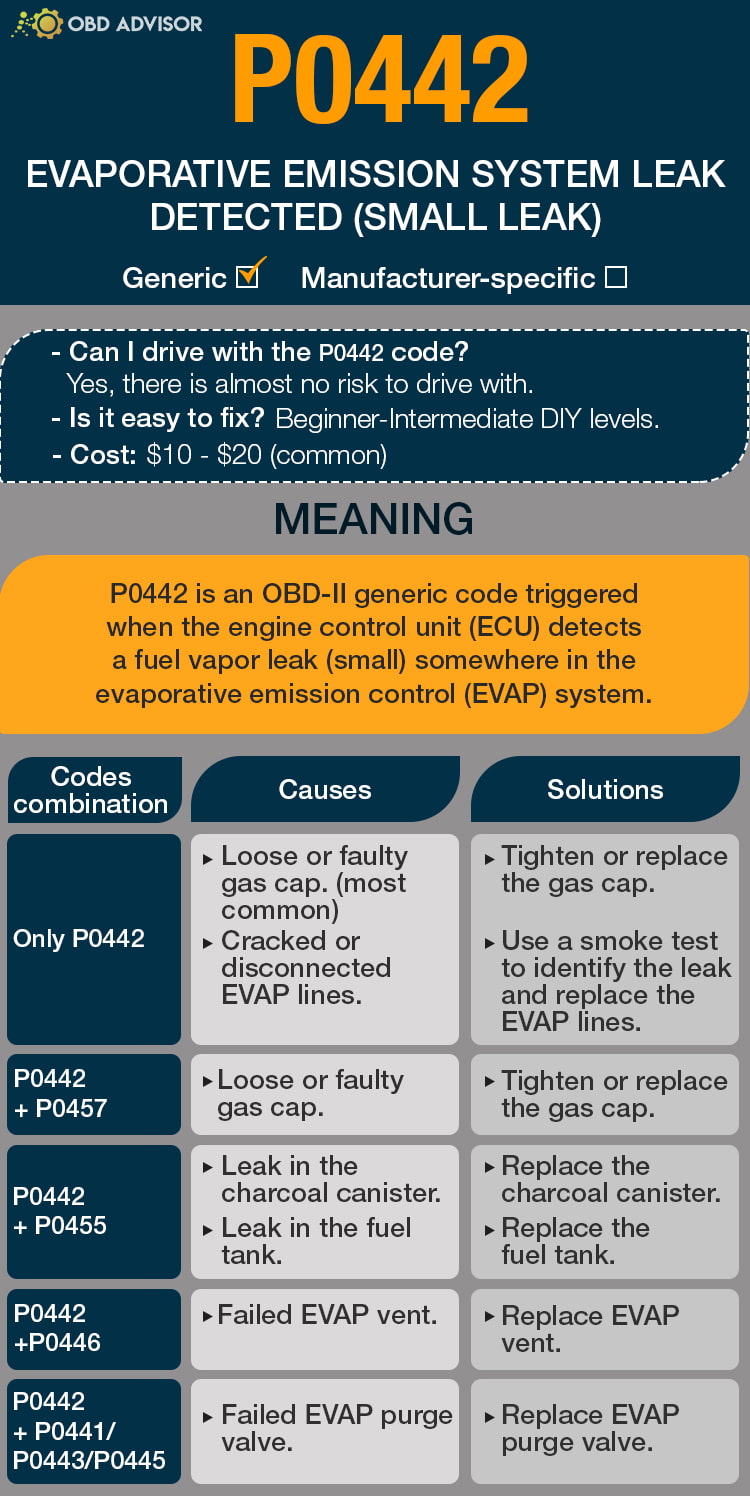
P0442 Causes Identification: Quick View
The EVAP system is built around several components, and most of the leaks are hard to detect as they could be present in any of these parts.
The table below will help identify possible causes for the leaks and their solutions.
| Codes Combination | Causes | Solutions |
|---|---|---|
| Only P0442 | Loose and faulty gas cap. Cracked or disconnected EVAP lines. | Tighten or replace the gas cap. Use a smoke test to identify the leak and replace the EVAP lines. |
| P0442 + P0457 | Loose and faulty gas cap. | Tighten or replace the gas cap. |
| P0442 + P0455 | Leak in the charcoal canister. Leak in the fuel tank. | Replace the charcoal canister. Replace the fuel tank. |
| P0442 +P0446 | Failed EVAP vent. | Replace EVAP vent. |
| P0442 + P0441/P0443/P0445 | Failed EVAP purge valve. | Replace the EVAP purge valve. |
Note: The causes for each code combination are the most common ones. There can be some uncommon issues hidden under those codes.
P0442: Causes, Symptoms, And How To Fix
It is important to understand what is causing the underlying problem to determine a solution.
Let’s look at some of the common causes of the P0442 error code and how you may go about fixing them.
Cause #1: Loose Or Faulty Gas Cap
Check your car’s gas cap first before moving on to further diagnosis.
Although a fuel cap may look pretty simple, it does play a vital role in preventing dirt, dust, and other particles from entering the fuel tank. The gas cap also acts as a seal, stopping the fuel vapors from escaping.
A faulty gas cap can cause the fuel vapors to leak into the atmosphere, resulting in the illuminated check engine light.
Cause #2: Cracked Or Disconnected EVAP Lines
You may be seeing the P0442 error code because of cracked or disconnected EVAP lines.
A running car can experience certain vibrations, causing the EVAP hose to disconnect and trigger the P0442 fault code.
On the other hand, cracked hoses are not so common as they’re not exposed to excessive heat. However, it can experience wear and tear due to age.
Symptoms of a faulty/disconnected EVAP line include:
- P0442 error code.
- Check engine light on.
- Poor engine performance.
- Hard start.
- Failed emissions test.
Check for any disconnected EVAP lines. If there are any, make sure to reconnect the lines and replace the clamps that hold the hoses in place.
However, it can be challenging to identify if you have a cracked EVAP line. You would need to conduct a smoke test to determine the leakage.
Cause #3: Leak In The Charcoal Canister
The charcoal canister captures the fumes in the EVAP system, which is then used to power the car’s engine.
After years of use, a charcoal canister may start to leak due to wear and tear, and if that occurs, it may cause the following symptoms:
- Combination of P0442 and P0455 error codes.
- Check engine light on.
- Failed emissions test.
- Reduced vehicle performance.
- Fuel smell coming from the vehicle.
A leaky charcoal canister can cause performance issues and require replacement. Buying a new one is relatively inexpensive.
You can even carry out the job at home with basic DIY skills. It’s just a matter of disconnecting the hoses and electrical connectors, removing the canister, and reconnecting everything.
Cause #4: Leak In The Fuel Tank
A gas tank is a durable car component and is placed in a protective area.
However, it can sustain damage from accidents or get punctured by road debris, resulting in a leak.
Here are some common signs that your fuel tank is leaking:
- Combination of P0442 and P0455 error codes.
- Fuel smell coming from the vehicle.
- A wet spot under the car.
- High fuel consumption.
You can repair the gas tank by using epoxy putty on smaller leaks and welding on larger leaking spots. But before you start welding, empty the fuel tank of any fuel and vapors.
It can often be a hassle to seal a fuel tank. It’s best to replace a leaky fuel tank with a new one.
Cause #5: Failed EVAP Vent
The vent assists the EVAP system by allowing air into the charcoal canister.
A faulty EVAP vent can prevent fresh air from entering the EVAP system, affecting its operations.
Some of the symptoms of a failed EVAP vent include:
- Combination of P0442 and P0446 error codes.
- Check engine light on.
- Pressure in the gas tank.
- Failed emissions test.
If your car has a failed EVAP vent, it’s time to buy a new one.
Cause #6: Failed EVAP Purge Valve
The EVAP purge valve is responsible for “purging” the EVAP system by acting as a switch that holds the fuel vapors in the charcoal canister and prevents them from leaking.
A failed EVAP purge valve will negatively affect the car’s emission output levels, indicating an evaporative emission system leak.
If you have a bad EVAP purge valve, you may experience the following symptoms:
- A combination of P0442 with either P0441/P0443/P0445.
- Rough idle.
- Poor engine performance.
- Difficulty starting.
- Low fuel economy.
- Check engine light on.
To fix this issue, purchase a new EVAP purge valve and replace it with the old one.
How Much Does It Cost To Fix P0442?
The most common cause of the P0442 is a faulty gas cap which can cost anywhere between $10 and $20, depending on your car’s make and model.
Other causes can set you back up to $1000 if the fuel tank is the problem. Below, we’ve broken down the repair costs (DIY or mechanic) according to the solutions.
The Estimated Repair Cost Of P0442
| Solutions | Cost |
|---|---|
| Replace gas cap | – DIY: $10 – $20 – Repair shop: not recommended |
| Replace EVAP lines | – DIY: $8 – $15 – Repair shop: $60 – $65 |
| Replace charcoal canister | – DIY: $80 – $250 – Repair shop: $130 – $350 |
| Replace fuel tank | – DIY: $600 – $800 – Repair shop: more than $1000 |
| Replace EVAP vent | – DIY: $30 – $150 – Repair shop: $60 – $250 |
| Replace EVAP purge valve | – DIY: $35 – $100 – Repair shop: $85 – $220 |
Note: The data in this table is collected in June 2022. The actual price depends on many factors, such as your car’s make and year, mechanic’s rate, etc.
You Ask, I Answer
Although a small leak in the EVAP system is not dangerous to drive with a P0442 error code for the short term, it is best to get it fixed.
I would like to thank you for sticking with me to the end.
If you have any questions or concerns about the error code P0442, please let me know in the comments section below, and I’ll try my best to answer your concerns.
See ya!
Read more: The 9 Best OBD2 Scanners for 2024: The Only Review You Need
P0120 Code: Understanding TPS “A” Circuit Malfunction
P0120 Code: Understanding TPS “A” Circuit Malfunction
If you’ve ever encountered the P0120 OBD-II trouble code, you know how frustrating it can be to have your vehicle’s check engine light illuminate. This code refers to the “Throttle/Pedal Position Sensor/Switch “A” Circuit” issue, which can cause several serious issues if not addressed.
In this article, we’ll take a comprehensive look at the P0120 code, including its severity, common symptoms, underlying causes, and the necessary diagnostic and repair steps. By understanding this information, you’ll be able to address the issue quickly and efficiently, getting your vehicle back on the road in no time.
So, let’s dive in.
P0120 Code: An Overview
Here is a summary of the P0120 code. Check it out!
- Definition: Throttle/Pedal Position Sensor/Switch “A” Circuit
- Severity: Medium
- DIY Skill Level: Intermediate
- Continue To Drive?: Yes (short-term)
- Estimated Repair Cost: $50 – $200
What Does The P0120 Code Mean?
P0120 is a diagnostic trouble code (DTC) that indicates there is a problem with the throttle position sensor (TPS) circuit, specifically circuit “A.”. While it is a generic code that can occur in various car makes and models, it is particularly more common in Chevrolet, Toyota, and Nissan among others.
The TPS is part of the engine management system, which controls the air-fuel mixture and other engine parameters to optimize performance and emissions. The TPS works together with the throttle valve and the Engine Control Unit (ECU) to ensure that the engine receives the correct amount of air.
When you press the accelerator pedal, the throttle valve opens, allowing more air to enter the engine. The TPS sends a signal to the ECU indicating the position of the throttle valve. The ECU then uses this information to calculate the correct amount of fuel to inject into the engine.
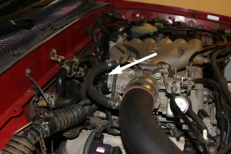
If the TPS “A” circuit is faulty, the TPS may not be able to send a signal to the ECU, or the ECU may not be able to receive the signal, triggering the code P0120. Specifically, when the ECM identifies that the voltage output from TPS circuit “A” exceeds the designated voltage range, in contrast to TPS sensor circuit “B,” the P0120 code is triggered. The specific voltage range may differ depending on the vehicle’s manufacturer and model.
Note: In some vehicle models, the ECU monitors the TPS and the manifold absolute pressure (MAP) sensor together. The ECU expects a consistent relationship between the throttle position and the manifold pressure. If there is a significant difference between the two, it can trigger the P0120 code.
How Severe Is P0120?
The P0120 code is of medium severity. While it doesn’t indicate an immediate danger or major mechanical failure, it should be addressed promptly to prevent potential issues from getting worse.
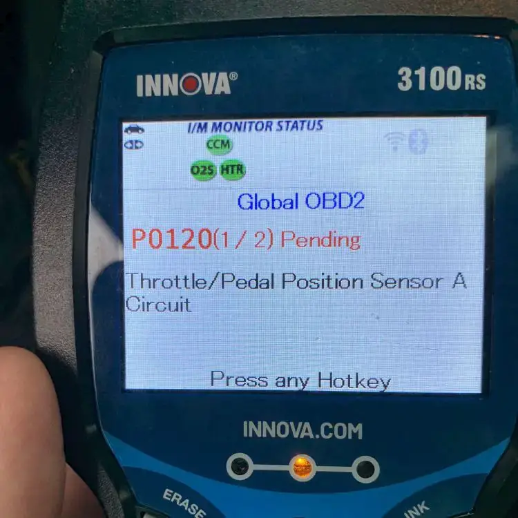
Driving with the P0120 code in the short term is generally safe. However, if ignored for a long time, it could cause reduced fuel efficiency, drivability problems, or even damage to other engine components.
To ensure your vehicle’s longevity and optimal performance, it’s recommended to have the code diagnosed and repaired as soon as possible. Consult a qualified mechanic to identify the root cause and make the necessary repairs. Taking this proactive approach will help prevent further complications in the future.
Read more: P0122 – Throttle/Pedal Position Sensor/Switch “A” Circuit Low
What Are The Symptoms of P0120?
When your vehicle experiences the P0120 code, you may notice the following symptoms:
- Check Engine Light (CEL) illuminated on the dashboard
- Failsafe mode
- Reduced engine power or lack of response when pressing the accelerator pedal
- Irregular or fluctuating idle speed
- Poor fuel efficiency
- Hard starting
Read more: P0121 – Throttle/Pedal position sensor/switch “A” circuit
What Causes P0120?
The P0120 code can be triggered by various underlying causes, including:
- Malfunctioning TPS sensor (most common)
- Damaged or frayed wiring in the TPS circuit
- Loose or poor electrical connections
- Corrosion or debris on the sensor or connectors
- Faulty ECM or related components such as accelerator position sensor, MAP sensor.
Read more: P1516 Chevy Code: Throttle Position Sensor Issues Explained
DIY Guide To Diagnosing and Repairing P0120
In this section, we’ll provide the tools and parts you’ll need, along with a step-by-step procedure to help you diagnose and fix the P0120 code yourself. By following this guide, you can save money on repairs and better understand your vehicle’s throttle position sensor.
Essential Tools and Parts
To diagnose and repair the P0120 code, you may need the following tools and parts:
- OBD-II scanner or code reader
- Multimeter
- TPS replacement (if necessary)
- Electrical contact cleaner
- Wire connectors and electrical tape (for wiring repairs)
Step-by-step Procedure
Step 1: Retrieve Stored DTCs
Connect the OBD-II scanner or code reader to retrieve the stored trouble codes and any additional relevant data.
Step 2: Inspect Throttle Pedal
Inspect the throttle pedal position sensor and its wiring for any signs of damage, such as frayed wires or loose connections. Pay close attention to the wiring harness near the sensor.
Step 3: Check the Sensor and Connector
Check for any corrosion or debris on the sensor or its connectors. Clean them if necessary to ensure proper electrical contact.
Step 4: Test Voltage Signals
Use a multimeter to test the voltage signals from the TPS circuit and compare them to specifications provided by the manufacturer. Ensure the TPS is receiving and transmitting the correct voltage signals. If the voltage signals are outside the expected range or erratic, replace the throttle position sensor.
Step 5: Inspect Related Components
Inspect other related components, such as the accelerator position sensor, MAP sensor, and their respective wiring connections, for any signs of damage or loose connections. Repair or replace as needed.
Step 6: Clear Codes and Test Drive
Clear the trouble codes using the OBD-II scanner and test drive the vehicle to ensure the issue has been resolved.
Note: It’s recommended to consult the vehicle’s service manual or seek professional assistance for specific diagnostic and repair steps tailored to your vehicle’s make and model.
DIY Repair Level and Estimated Costs
Diagnosing the P0120 code can be moderately challenging, requiring some technical knowledge and the use of specialized tools. The level of DIY repair for this code is considered intermediate.
The estimated costs for the main repair tasks associated with the P0120 code can vary depending on factors such as the vehicle make, model, and the specific cause of the issue. Here’s a general breakdown of potential costs:
| Repair Task | Estimated Cost Range |
| Diagnostic Fee | $50 – $100 |
| Wiring Repair | $50 – $200 |
| Throttle Position Sensor Replacement | $60 – $100 (aftermarket part)$100 – $200 (OEM part) |
Remember, if you’re unsure about any step or lack the necessary tools and expertise, it’s always advisable to consult with a qualified mechanic or automotive technician to ensure proper diagnosis and repair. They can provide accurate guidance and ensure the issue is resolved effectively and safely.
Final Thoughts
Understanding the P0120 OBD-II trouble code is super important to keep your vehicle running smoothly. By knowing the signs to look out for, the possible causes, and the steps for diagnosing and fixing the issue, you’ll feel confident handling the problem and avoiding any additional headaches. Of course, it’s always a good idea to reach out to a qualified mechanic for expert advice and assistance.
If you found this information helpful, feel free to share it with fellow car enthusiasts. Don’t forget to leave a comment below sharing your experiences or questions.
Stay informed and keep your car running smoothly!
Reference Sources
AutoZone, Symptoms of a Bad Throttle Position Sensor.
Autoditex, THROTTLE POSITION SENSOR (TPS).
Honda OBD2 Codes List [Generic + Manufacturer-specific]
Honda OBD2 Codes List [Generic + Manufacturer-specific]
Are you tired of seeing that pesky “Check Engine” light on your Honda, but have no idea what’s causing it?
Don’t worry! We’ve got you covered.
With both generic and manufacturer-specific codes included, our guide is organized in an easy-to-read format with detailed descriptions for each code. You’ll be able to diagnose your Honda’s problem quickly and accurately.
We also offer the complete list of Honda OBD2 codes for FREE download.
So, take advantage of it – read until the end!
Honda OBD2 Codes List and Meaning [FULL]
Free Download: Full Honda OBD2 Trouble Codes List and Meaning PDF
Our user-friendly code list is divided into four parts: Powertrain, Network, Body, and Chassis, which helps you easily find the codes you need for engine, network, body control, and chassis issues.
Note: Use the search box in the table below to quickly find the specific code you’re looking for.
Powertrain (P) Codes List
| Code | Definition |
|---|---|
| P0010 | Variable Valve Timing Control (VTC) Oil Control Solenoid Valve Malfunction |
| P0011 | Variable Valve Timing Control (VTC) System Malfunction |
| P0101 | Mass Airflow (MAF) Sensor Range/Performance Problem |
| P0102 | Mass Airflow (MAF) Sensor Circuit Low Voltage |
| P0103 | Mass Airflow (MAF) Sensor Circuit High Voltage |
| P0106 | Manifold Absolute Pressure (MAP) Sensor Range/Performance Problem |
| P0107 | Manifold Absolute Pressure (MAP) Sensor Circuit Low Voltage |
| P0108 | Manifold Absolute Pressure (MAP) Sensor Circuit High Voltage |
| P0111 | Intake Air Temperature (IAT) Sensor Circuit Range/Performance Problem |
| P0112 | Intake Air Temperature (IAT) Sensor Circuit Low Voltage |
| P0113 | Intake Air Temperature (IAT) Sensor Circuit High Voltage |
| P0116 | Engine Coolant Temperature (ECT) Sensor Circuit Range/Performance Problem |
| P0117 | Engine Coolant Temperature (ECT) Sensor Circuit Low Input |
| P0118 | Engine Coolant Temperature (ECT) Sensor Circuit High Input |
| P0122 | Throttle Position (TP) Sensor Circuit Low Input |
| P0123 | Throttle Position (TP) Sensor Circuit High Input |
| P0125 | Engine Coolant Temperature (ECT) Sensor Slow Response |
| P0128 | Cooling System Malfunction |
| P0131 | Primary Heated Oxygen Sensor (Primary HO2S) (Sensor 1) Circuit Low Voltage |
| P0132 | Primary Heated Oxygen Sensor (Primary HO2S) (Sensor 1) Circuit High Voltage |
| P0133 | Rear Air/Fuel Ratio (A/F) Sensor (Bank 1, Sensor 1) Circuit Slow Response |
| P0134 | Air/Fuel Ratio (A/F) Sensor (Sensor 1) No Activity Detected |
| P0135 | Primary Heated Oxygen Sensor (Primary HO2S) (Sensor 1) Heater Circuit Malfunction |
| P0137 | Secondary Heated Oxygen Sensor (Secondary HO2S) Circuit Low Voltage |
| P0138 | Secondary Heated Oxygen Sensor (Secondary HO2S) Circuit High Voltage |
| P0139 | Secondary Heated Oxygen Sensor (Secondary HO2S) Slow Response |
| P0141 | Secondary Heated Oxygen Sensor (Secondary HO2S) (Sensor 2) Heater Circuit Malfunction |
| P0143 | Third Heated Oxygen Sensor (Third HO2S) (Sensor 3) Circuit Low Voltage |
| P0144 | Third Heated Oxygen Sensor (Third HO2S) (Sensor 3) Circuit High Voltage |
| P0145 | Third Heated Oxygen Sensor (Third HO2S) (Sensor 3) Circuit Slow Response |
| P0147 | Third Heated Oxygen Sensor (Third HO2S) (Sensor 3) Heater Circuit Malfunction |
| P0153 | Front Air/Fuel Ratio (A/F) Sensor (Bank 2, Sensor 1) Circuit Slow Response |
| P0154 | Front Air/Fuel Ratio (A/F) Sensor (Bank 2, Sensor 1) Heater System Malfunction |
| P0155 | Front Air/Fuel Ratio (A/F) Sensor (Bank 2, Sensor 1) Heater Circuit Malfunction |
| P0157 | Front Secondary Heated Oxygen Sensor (Secondary HO2S) (Bank 2, Sensor 2) Circuit Low Voltage |
| P0158 | Front Secondary Heated Oxygen Sensor (Secondary HO2S) (Bank 2, Sensor 2) Circuit High Voltage |
| P0159 | Front Secondary Heated Oxygen Sensor (Secondary HO2S) (Bank 2, Sensor 2) Circuit Slow Response |
| P0161 | Front Secondary Heated Oxygen Sensor (Secondary HO2S) (Bank 2, Sensor 2) Heater Circuit Malfunction |
| P0171 | Fuel System Too Lean |
| P0172 | Fuel System Too Rich |
| P0174 | Front Bank (Bank 2) Fuel System Too Lean |
| P0175 | Front Bank (Bank 2) Fuel System Too Rich |
| P0191 | Fuel Pressure Sensor Range/Performance Problem |
| P0192 | Fuel Pressure Sensor Circuit Low Voltage |
| P0193 | Fuel Pressure Sensor Circuit High Voltage |
| P0196 | EOT Sensor/Range Performance Problem |
| P0197 | EOT Sensor Circuit Low Voltage |
| P0198 | EOT Sensor Circuit High Voltage |
| P0222 | Throttle Position (TP) Sensor 2 Circuit Low Voltage |
| P0223 | Throttle Position (TP) Sensor 2 Circuit High Voltage |
| P0300 | Random Misfire |
| P0301 | No. 1 Cylinder Misfire |
| P0302 | No. 2 Cylinder Misfire |
| P0303 | No. 3 Cylinder Misfire |
| P0304 | No. 4 Cylinder Misfire |
| P0305 | No. 5 Cylinder Misfire |
| P0306 | No. 6 Cylinder Misfire |
| P0325 | Knock Sensor Circuit Malfunction |
| P0335 | Crankshaft Position (CKP) Sensor Circuit No Signal |
| P0336 | Crankshaft Position (CKP) Sensor Circuit Range/Performance |
| P0339 | Crankshaft Position (CKP) Sensor Circuit Intermittent Interruption |
| P0340 | Camshaft Position (CMP) Sensor No Signal |
| P0341 | Camshaft Position (CMP) Sensor A Intermittent Interruption |
| P0341 | Variable Valve Timing Control (VTC) Phase Gap |
| P0344 | Camshaft Position (CMP) Sensor Intermittent Interruption |
| P0365 | Camshaft Position (CMP) Sensor B No Signal |
| P0366 | Camshaft Position (CMP) Sensor B Range/Performance |
| P0369 | Camshaft Position (CMP) Sensor B Intermittent Interruption |
| P0385 | Crankshaft Position (CKP) Sensor B No Signal |
| P0389 | Crankshaft Position (CKP) Sensor B Intermittent Interruption |
| P0401 | Exhaust Gas Recirculation (EGR) Insufficient Flow |
| P0404 | Exhaust Gas Recirculation (EGR) Control Circuit Range/Performance Problem |
| P0406 | Exhaust Gas Recirculation (EGR) Valve Position Sensor Circuit High Voltage |
| P0410 | Air Pump Circuit Malfunction |
| P0411 | Secondary Air Injection System Incorrect Flow |
| P0420 | Catalyst System Efficiency Below Threshold |
| P0430 | Front Bank Catalyst System Efficiency Below Threshold (Bank 2) |
| P0441 | Evaporative Emission (EVAP) Control System Incorrect Purge Flow |
| P0442 | Evaporative Emission (EVAP) System Small Leak Detected |
| P0443 | Evaporative Emission (EVAP) Canister Purge Valve Circuit Malfunction |
| P0451 | Fuel Tank Pressure (FTP) Sensor Range/Performance Problem |
| P0452 | Fuel Tank Pressure (FTP) Sensor Circuit Low Voltage |
| P0453 | Fuel Tank Pressure (FTP) Sensor Circuit High Voltage |
| P0456 | Evaporative Emission (EVAP) System Very Small Leak Detected |
| P0457 | Evaporative Emission (EVAP) System Leak Detected Fuel Fill Cap Loose/Off |
| P0461 | Fuel Gauge Sending Unit Range/Performance Problem |
| P0462 | Fuel Gauge Sending Unit Circuit Low Voltage |
| P0463 | Fuel Gauge Sending Unit Circuit High Voltage |
| P0496 | Evaporative Emission (EVAP) System High Purge Flow |
| P0497 | Evaporative Emission (EVAP) System Low Purge Flow |
| P0498 | Evaporative Emission (EVAP) Canister Vent Shut Valve Control Circuit Low Voltage |
| P0499 | Evaporative Emission (EVAP) Canister Vent Shut Valve Control Circuit High Voltage |
| P0500 | Vehicle Speed Sensor (VSS) Circuit Malfunction |
| P0501 | Vehicle Speed Sensor (VSS) Range/Peformance Problem |
| P0505 | Idle Control System Malfunction |
| P0506 | Idle Control System RPM Lower Than Expected |
| P0507 | Idle Control System RPM Higher Than Expected |
| P0511 | Idle Air Control (IAC) Valve Circuit Malfunction |
| P0521 | EOP Sensor Range/Performance Problem |
| P0522 | EOP Sensor Circuit Low Voltage |
| P0523 | EOP Sensor Circuit High Voltage |
| P0560 | ECM Back-up Circuit Low Voltage |
| P0563 | Engine Control Module (ECM)/Powertrain Control Module (PCM) Power Source Circuit Unexpected Voltage |
| P0600 | Multiplex Control System Troubleshooting |
| P0603 | ECM/PCM Internal Control Module Keep Alive Memory (KAM) Error |
| P0606 | ECM/PCM Processor Malfunction |
| P0661 | Intake Manifold Runner Control (IMRC) Valve Position Sensor Circuit Low Voltage |
| P0662 | Intake Manifold Runner Control (IMRC) Valve Position Sensor Circuit High Voltage |
| P0685 | ECM/PCM Power Relay Control Circuit Malfunction |
| P0700 | Automatic Transmission Control System |
| P0705 | Short in Transmission Range Switch Circuit (Multiple Shift-position Input) |
| P0706 | Open in Transmission Range Switch Circuit |
| P0710 | Transmission Fluid Temperature Sensor Circuit Fault |
| P0711 | Problem in ATF Temperature Sensor Circuit |
| P0712 | Short in ATF Temperature Sensor Circuit |
| P0713 | Open in ATF Temperature Sensor Circuit |
| P0715 | Input Shaft Speed Sensor Circuit Malfunction |
| P0716 | Problem in Mainshaft Speed Sensor Circuit |
| P0717 | Problem in Mainshaft Speed Sensor Circuit (No Signal Input) |
| P0718 | Mainshaft Speed Sensor Intermittent Failure |
| P0720 | Countershaft Speed Sensor Circuit Malfunction |
| P0721 | Problem in Countershaft Speed Sensor Circuit |
| P0722 | Problem in Countershaft Speed Sensor Circuit (No Signal Input) |
| P0723 | Countershaft Speed Sensor Intermittent Failure |
| P0725 | Engine Speed Input Circuit Malfunction |
| P0730 | Problem in Shift Control System |
| P0731 | Problem in 1st Clutch and 1st Clutch Hydraulic Circuit |
| P0732 | Problem in 2nd Clutch and 2nd Clutch Hydraulic Circuit |
| P0733 | Problem in 3rd Clutch and 3rd Clutch Hydraulic Circuit |
| P0734 | Problem in 4th Clutch and 4th Clutch Hydraulic Clutch |
| P0735 | Problem in 5th Clutch and 5th Clutch Hydraulic Circuit |
| P0740 | Problem in Lock-up Control System |
| P0741 | Torque Converter Clutch Hydraulic Clutch Stuck OFF |
| P0743 | Problem in Torque Converter Clutch Solenoid Valve Circuit |
| P0745 | Problem in Hydraulic Control System of A/T Clutch Pressure Control Solenoid Valve A Circuit |
| P0746 | A/T Clutch Pressure Control Solenoid Valve A Stuck OFF |
| P0747 | A/T Clutch Pressure Control Solenoid Valve A Stuck ON |
| P0748 | Problem in A/T Clutch Pressure Control Solenoid Valve A Circuit |
| P0750 | Problem in Hydraulic Control System of Shift Solenoid Valve A Circuit |
| P0751 | Shift Solenoid Valve A Stuck OFF |
| P0752 | Shift Solenoid Valve A Stuck ON |
| P0753 | Problem in Shift Solenoid Valve A Circuit |
| P0756 | Shift Solenoid Valve B Stuck OFF |
| P0757 | Shift Solenoid Valve B Stuck ON |
| P0758 | Problem in Shift Solenoid Valve B Circuit |
| P0761 | Shift Solenoid Valve C Stuck OFF |
| P0762 | Shift Solenoid Valve C Stuck ON |
| P0763 | Problem in Shift Solenoid Valve C Circuit |
| P0771 | Shift Solenoid Valve E Stuck OFF |
| P0773 | Problem in Shift Solenoid Valve E Circuit |
| P0775 | Problem in the Hydraulic Control System of A/T Clutch Pressure Control Solenoid Valve B Circuit |
| P0776 | A/T Clutch Pressure Control Solenoid Valve B Stuck OFF |
| P0777 | A/T Clutch Pressure Control Solenoid Valve B Stuck ON |
| P0778 | Problem in A/T Clutch Pressure Control Solenoid Valve B Circuit |
| P0780 | Problem in Shift Control System |
| P0795 | Problem in Hydraulic Control System of A/T Clutch Pressure Control Solenoid Valve C Circuit |
| P0796 | A/T Clutch Pressure Control Solenoid Valve C Stuck OFF |
| P0797 | A/T Clutch Pressure Control Solenoid Valve C Stuck ON |
| P0798 | Problem in A/T Clutch Pressure Control Solenoid Valve C Ciruit |
| P0812 | Open in Transmission Range Switch ATP RVS Switch Circuit |
| P0842 | Short in 2nd Clutch Transmission Fluid Pressure Switch Clutch, or 2nd Clutch Transmission Fluid Pressure Switch (Clutch) Stuck ON |
| P0843 | Open in 2nd Clutch Transmission Fluid Pressure Switch Circuit, or 2nd Clutch Transmission Fluid Pressure Switch Stuck OFF |
| P0845 | Problem in 3rd Clutch Pressure Switch Circuit |
| P0847 | Short in 3rd Clutch Transmission Fluid Pressure Switch Circuit, or 3rd Clutch Transmission Fluid Pressure Switch Stuck ON |
| P0848 | Open in 3rd Clutch Transmission Fluid Pressure Switch Circuit, or 3rd Clutch Transmission Fluid Pressure Switch Stuck OFF |
| P0872 | Short in 4th Clutch Transmission Fluid Pressure Switch Circuit, or 4th Clutch Transmission Fluid Pressure Switch Stuck ON |
| P0873 | Open in 4th Clutch Transmission Fluid Pressure Switch Circuit, or 4th Clutch Transmission Fluid Pressure Switch Stuck OFF |
| P0962 | Problem in A/T Clutch Pressure Control Solenoid Valve A Circuit |
| P0963 | Problem in A/T Clutch Pressure Control Solenoid Valve A |
| P0966 | Problem in A/T Clutch Pressure Control Solenoid Valve B Circuit |
| P0967 | Problem in A/T Clutch Pressure Control Solenoid Valve B |
| P0970 | Problem in A/T Clutch Pressure Control Solenoid Valve C Circuit |
| P0971 | Problem in A/T Clutch Pressure Control Solenoid Valve C |
| P0973 | Short in Shift Solenoid Valve A Circuit |
| P0974 | Open in Shift Solenoid Valve A Circuit |
| P0976 | Short in Shift Solenoid Valve B Circuit |
| P0977 | Open in Shift Solenoid Valve B Circuit |
| P0979 | Short in Shift Solenoid Valve C Circuit |
| P0980 | Open in Shift Solenoid Valve C Circuit |
| P0982 | Short in Shift Solenoid Valve D Circuit |
| P0983 | Open in Shift Solenoid Valve D Circuit |
| P0985 | Short in Shift Solenoid Valve E Circuit |
| P0986 | Open in Shift Solenoid Valve E Circuit |
| P1020 | Valve Pause System Stuck Off |
| P1021 | Valve Pause System Stuck On |
| P1025 | Valve Pause System Sticking Off |
| P1026 | Valve Pause System Sticking On |
| P1077 | Intake Manifold Runner Control (IMRC) System Malfunction (Low rpm) |
| P1078 | Intake Mainfold Runner Control (IMRC) System Malfunction (High rpm) |
| P1106 | Barometric Pressure (BARO) Sensor Circuit Range/Performance Problem |
| P1107 | Barometric Pressure (BARO) Sensor Circuit Low Voltage |
| P1108 | Barometric Pressure (BARO) Sensor Circuit High Voltage |
| P1121 | Throttle Position (TP) Sensor Lower Than Expected |
| P1122 | Throttle Position (TP) Sensor Higher Than Expected |
| P1128 | Manifold Absolute Pressure (MAP) Sensor Circuit Lower Than Expected |
| P1129 | Manifold Absolute Pressure (MAP) Sensor Circuit Higher Than Expected |
| P1130 | Demand for Changing Both Secondary Heated Oxygen Sensor (Secondary HO2S) (Sensor 2) and Third Heated Oxygen Sensor (Third HO2S) (Sensor 3) |
| P1149 | Air/Fuel Ratio (A/F) Sensor (Sensor 1) Range/Performance Problem |
| P1149 | Air/Fuel Ratio Sensor (Sensor 1) Circuit Lean Range |
| P1157 | Air/Fuel Ratio (A/F) Sensor (Sensor 1) AFS Line High Voltage |
| P1157 | Air/Fuel Ratio (A/F) Sensor (Sensor 1) Circuit High Voltage |
| P1157 | Air/Fuel Ratio (A/F) Sensor (Sensor 1) Range/Performance Problem |
| P1158 | Air/Fuel Ratio (A/F) Sensor (Sensor 1) AFS- Terminal Low Voltage |
| P1159 | Air/Fuel Ratio (A/F) Sensor (Sensor 1) AFS+ Terminal Low Voltage |
| P1162 | Air/Fuel Ratio (A/F) Sensor (Sensor 1) Slow Response |
| P1163 | Air/Fuel Ratio (A/F) Sensor (Sensor 1) Slow Response |
| P1163 | Air/Fuel Ratio Sensor (Sensor 1) Slow Response |
| P1164 | Air/Fuel Ratio (A/F) Sensor (Sensor 1) Range/Performance Problem |
| P1164 | Air/Fuel Ratio (AF) Sensor (Sensor 1) Circuit Range/Performance |
| P1165 | Air/Fuel Ratio (A/F) Sensor (Sensor 1) Range/Performance Problem |
| P1165 | Air/Fuel Ratio Sensor (Sensor 1) Circuit Range/Performance |
| P1166 | Air/Fuel Ratio (A/F) Sensor (Sensor 1) Heater System Electrical Problem |
| P1166 | Heated Oxgen Sensor Sensor1 (Primary HO2S) Heater Circuit Malfunction |
| P1167 | Air/Fuel Ratio (A/F) Sensor (Sensor 1) Heater System Malfunction |
| P1167 | Heated Oxygen Sensor Sensor1 (Primary LAF HO2S) Heater System Malfunction |
| P1168 | Air/Fuel Ratio (A/F) Sensor (Sensor 1) LABEL Low Voltage |
| P1169 | Air/Fuel Ratio (A/F) Sensor (Sensor 1) LABEL High Voltage |
| P1182 | Fuel Temperature Sensor Circuit Low Voltage |
| P1183 | Fuel Temperature Sensor Circuit High Voltage |
| P1253 | VTEC System Malfunction |
| P1259 | VTEC System Malfunction |
| P1297 | Electric Load Detector (ELD) Circuit Low Voltage |
| P1298 | Electric Load Detector (ELD) Circuit High Voltage |
| P1300 | Random Misfire |
| P1324 | Knock Sensor Power Source Circuit Low Voltage |
| P1336 | Engine Speed (RPM) Fluctuation Sensor Intermittent Interruption |
| P1337 | Engine Speed (RPM) Fluctuation Sensor No Signal |
| P1355 | Front Ignition Coil Power Circuit Malfunction |
| P1359 | Crankshaft Position (CKP)/Top Dead Center (TDC) Sensor Circuit Malfunction |
| P1361 | Camshaft Position (CMP) Sensor A (Top Dead Center (TDC) Sensor) Intermittent Interruption |
| P1361 | Top Dead Center (TDC) Sensor Intermittent Interruption |
| P1362 | Camshaft Position (CMP) Sensor A (Top Dead Center (TDC) Sensor) No Signal |
| P1362 | Top Dead Center (TDC) Sensor No Signal |
| P1366 | Camshaft Position (CMP) Sensor B (Top Dead Center (TDC) Sensor) Intermittent Interruption |
| P1366 | Top Dead Center (TDC) Sensor 2 Intermittent Interruption |
| P1367 | Camshaft Position (CMP) Sensor B (Top Dead Center (TDC) Sensor) No Signal |
| P1367 | Top Dear Center (TDC) Sensor 2 No Signal |
| P1381 | Cylinder Position (CYP) Sensor Intermittent Interruption |
| P1382 | Cylinder Position (CYP) Sensor No Signal |
| P1410 | Air Pump Malfunction |
| P1415 | Air Pump Electric Current Sensor Circuit Low Voltage |
| P1416 | Air Pump Electric Current Sensor Circuit High Voltage |
| P1420 | Nox Adsorptive Catalyst System Efficiency Below Threshold |
| P1438 | Motor Drive Module (MDM) Overheating Signal Circuit |
| P1438 | Motor Drive Module (MDM) Overheating |
| P1439 | Motor Drive Module (MDM) Short Circuit Sensor Problem |
| P1439 | Motor Drive Module (MDM) Short Circuit |
| P1440 | IMA System Problem |
| P1445 | Bypass Control Problem |
| P1448 | Battery Module Overheating |
| P1449 | Battery Module Overheating |
| P1449 | Battery Cell Overheating |
| P1449 | Battery Module Individual Voltage Input Deviation |
| P1449 | Battery Module Deterioration |
| P1449 | Battery Module Deviation |
| P1454 | Fuel Tank Pressure (FTP) Sensor Range/Performance Problem |
| P1456 | Evaporative Emissions (EVAP) Control System Leakage (Fuel Tank System) |
| P1457 | Evaporative Emissions (EVAP) Control System Leakage (EVAP Canister System) |
| P1459 | Evaporative Emission (EVAP) Purge Flow Switch Malfunction |
| P1491 | Exhaust Gas Recirculation (EGR) Valve Insufficient Lift |
| P1486 | Cooling System Malfunction |
| P1491 | Exhaust Gas Recirculation (EGR) Valve Insufficient Lift |
| P1498 | Exhaust Gas Recirculation (EGR) Valve Position Sensor Circuit High Voltage |
| P1505 | Positive Crankcase Ventilation (PCV) Air Leakage |
| P1508 | Idle Air Control Valve Circuit Malfunction |
| P1519 | Idle Air Control Valve (IACV) Circuit Malfunction |
| P1509 | Idle Air Control Valve (IACV) Circuit Failure |
| P1522 | Brake Booster Pressure Sensor Circuit Low Voltage |
| P1523 | Brake Booster Pressure Sensor Circuit High Voltage |
| P1524 | Brake Booster Pressure Sensor Range/Performance Problem |
| P1541 | Climate Control Unit Signal Circuit Low Voltage |
| P1542 | Climate Control Unit Signal Circuit High Voltage |
| P1565 | Motor Commutation Signal Problem |
| P1568 | Battery Module Individual Voltage Input Problem |
| P1568 | Battery Module Temperature Signal Circuit Problem |
| P1568 | Battery Cell Temperature Signal Circuit Problem |
| P1572 | Motor Drive Module (MDM) Temperature Signal Circuit Low Input |
| P1572 | Motor Drive Module (MDM) Temperature Signal Circuit High Input |
| P1576 | Motor Drive Module (MDM) Voltge Signal Circuit Low Input |
| P1577 | High Voltage Detection Signal Circuit Problem |
| P1580 | Battery Current Circuit Problem |
| P1581 | Motor Power Inverter (MPI) Module Current Signal Circuit Low Input |
| P1581 | Motor Power Inverter (MPI) Module Current Signal Circuit High Input |
| P1581 | Motor Power Inverter (MPI) Module Current Signal Circuit Problem |
| P1582 | Motor Current U Phase Signal Circuit Low Input |
| P1582 | Motor Current U Phase Signal Circuit High Input |
| P1583 | Motor Current V Phase Signal Circuit Low Input |
| P1583 | Motor Current V Phase Signal Circuit High Input |
| P1584 | Motor Current W Phase Signal Circuit Low Input |
| P1584 | Motor Current W Phase Signal Circuit High Input |
| P1585 | Motor Current Signal Circuit Problem |
| P1586 | Motor Power Inverter (MPI) Module Current Signal/Battery Current Signal Circuit Problem |
| P1607 | Engine Control Module (ECM)/Powertrain Control Module (PCM) Internal Circuit Malfunction |
| P1630 | Transmission Control Module |
| P1635 | Battery Condition Monitor (BCM) Module Proble |
| P1639 | MOTB Signal Circuit Malfunction |
| P1640 | ACTTRQ Motor Torque Signal Circuit Low Input |
| P1641 | ACTTRQ Motor Torque Signal Circuit High Input |
| P1642 | QBATT Battery Signal Circuit Low Input |
| P1643 | QBATT Battery Signal Circuit High Input |
| P1644 | MOTFSA Signal Malfunction |
| P1645 | MOTFSB Signal Malfunction |
| P1646 | MOTSTB Signal Malfunction |
| P1647 | Power Command Signal Circuit Low Input |
| P1647 | Power Command Signal Circuit High Input |
| P1647 | Engine Torque Signal Circuit Low Input |
| P1647 | Engine Torque Signal Circuit High Input |
| P1647 | Mode Signal Circuit 1 Low Input |
| P1647 | Mode Signal Circuit 1 High Input |
| P1647 | Mode Signal Circuit 2 Problem |
| P1647 | Engine Speed Signal Circuit Problem |
| P1648 | Battery Condition Monitor (BCM) Module Communication Signal Circuit Problem |
| P1648 | Motor Control Module (MCM) Communication Signal Circuit Problem |
| P1655 | CVT-FI TMA/TMB Signal Line Failure |
| P1656 | Problem in PCM-toVTM-4 Control Unit Communications Circuit |
| P1660 | A/T-FI Data Line Failure/TCM – ECM Halt |
| P1676 | ABS/TCS Control Module Communication Malfunction |
| P1678 | FPTDR Signal Line Failure |
| P1679 | RSCD Signal Circuit Malfunction |
| P1681 | A/T FI Signal A Cicuit Low Voltage |
| P1682 | A/T FI Signal A Circuit High Voltage |
| P1683 | Throttle Valve Default Position Spring Performance Problem |
| P1684 | Throttle Valve Return Spring Performance Problem |
| P1686 | A/T FI Signal B Circuit Low Voltage |
| P1687 | A/T FI Signal B Circuit High Voltage |
| P1705 | Short in Transmission Range Switch Circuit (More than one range position is on at the same time) |
| P1706 | Open in Transmission Range Switch Circuit |
| P1709 | Problem Transmission Gear Selection Switch Circuit |
| P1730 | Problem in Shift Control System: Shift Solenoid Valve A and D Stuck OFF Shift Solenoid Valve B Stuck ON Shift Valves A, B, and D Stuck |
| P1731 | Problem in Shift Control System: Shift Solenoid Valve E Stuck ON Shift Valve E Stuck A/T Clutch Pressure Control Solenoid Valve A Stuck OFF |
| P1732 | Problem in Shift Control System: Shift Solenoid Valve B and C Stuck ON Shift Valves B and C Stuck |
| P1733 | Problem in Shift Control System: Shift Solenoid Valve D Stuck ON Shift Valve D Stuck A/T Clutch Pressure Control Solenoid Valve C Stuck OFF |
| P1734 | Problem in Shift Control System: Shift Solenoid Valves B and C Stuck ON Shift Valves B and C Stuck |
| P1738 | Problem in 2nd Clutch Pressure Switch Circuit |
| P1739 | Problem in 3rd Clutch Pressure Switch Circuit |
| P1740 | Problem in 4th Clutch Pressure Switch Circuit |
| P1750 | Mechanical Problem in Hydraulic Control System of A/T Clutch Pressure Control Solenoid Valve Assemblies A and B, or Problem in the Hydraulic Control System |
| P1751 | Mechanical Problem in Hydraulic Control System of Shift Solenoid Valve B and A/T Clutch Pressure Control Solenoid Valves A and B, or Problem in the Hydraulic Control System |
| P1753 | Problem in Torque Converter Clutch Solenoid Valve Circuit |
| P1751 | Mechanical Problem In Hydraulic Control System Of Shift Solenoid Valve ‘B’ |
| P1768 | Problem in Torque Converter Clutch Solenoid Valve B Circuit |
| P1773 | Problem in A/T Clutch Pressure Control Solenoid Valve B Circuit |
| P1790 | Throttle Position (TP) Sensor Circuit Malfunction |
| P1791 | Vehicle Speed Sensor (VSS) Range/Performance Problem |
| P1792 | Problem in Engine Coolant Temperature (ECT) Sensor Circuit |
| P1793 | Manifold Absolute Pressure Sensor Circuit |
| P1870 | Problem in CVT Speed Change Control Valve Assembly Circuit |
| P1873 | Problem in CVT Pulley Pressure Control Valve Assembly Circuit |
| P1879 | Problem in CVT Start Clutch Pressure Control Valve Assembly Circuit |
| P1882 | Problem in Inhibitor Solenoid Circuit |
| P1884 | Secondary Gear Speed Sensor 2 Circuit Malfunction |
| P1885 | CVT Drive Pulley Speed Sensor Circuit |
| P1886 | CVT Driven Pulley Speed Sensor Circuit |
| P1888 | CVT Speed Sensor |
| P1889 | Problem in CVT Speed Sensor 2 Circuit |
| P1890 | Shift Control System |
| P1891 | Problem in Start Clutch System |
| P1894 | CVT Speed Change Control Valve Circuit |
| P1895 | CVT Pulley Pressure Control Valve Circuit |
| P2101 | Throttle Actuator System Malfunction |
| P2108 | Throttle Actuator Control Module Problem |
| P2118 | Throttle Actuator Current Range/Performance Problem |
| P2122 | Accelerator Pedal Position (APP) Sensor 1 (Throttle Position Sensor D) Circuit Low Voltage |
| P2123 | Accelerator Pedal Position (APP) Sensor 1 (Throttle Position Sensor D) Circuit High Voltage |
| P2127 | Accelerator Pedal Position (APP) Sensor 2 (Throttle Position Sensor E) Circuit Low Voltage |
| P2128 | Accelerator Pedal Position (APP) Sensor 2 (Throttle Position Sensor E) Circuit High Voltage |
| P2135 | Throttle Position (TP) Sensor 1/2 Incorrect Voltage Correlation |
| P2138 | Accelerator Pedal Position (APP) Sensor 1/2 (Throttle Position Sensor D/E) Incorrect Voltage Correlation |
| P2176 | Throttle Actuator Control System Idle Position Not Learned |
| P2195 | Air/Fuel Ratio (A/F) Sensor (Sensor 1) Signal Stuck Lean |
| P2197 | Front Air/Fuel Ratio (A/F) Sensor (Bank 2, Sensor 1) Signal Stuck Lean |
| P2227 | Barometric Pressure (BARO) Sensor Circuit Range/Performance Problem |
| P2228 | Barometric Pressure (BARO) Sensor Circuit Low Voltage |
| P2229 | Barometric Pressure (BARO) Sensor Circuit High Voltage |
| P2237 | Rear Air/Fuel Ratio (A/F) Sensor (Bank 1, Sensor 1) IP Line High Voltage |
| P2238 | Air/Fuel Ratio (A/F) Sensor (Sensor 1) AFS+ Line Low Voltage |
| P2238 | Rear Air/Fuel Ratio (A/F) Sensor (Bank 1, Sensor 1) IP Line Low Voltage |
| P2240 | Front Air/Fuel Ratio (A/F) Sensor (Bank 2, Sensor 1) IP Line High Voltage |
| P2241 | Front Air/Fuel Ratio (A/F) Sensor (Bank 2, Sensor 1) IP Line Low Voltage |
| P2243 | Rear Air/Fuel Ratio (A/F) Sensor (Bank 1, Sensor 1) VCENT Line High Voltage |
| P2245 | Rear Air/Fuel Ratio (A/F) Sensor (Bank 1, Sensor 1) VCENT Line Low Voltage |
| P2247 | Front Air/Fuel Ratio (A/F) Sensor (Bank 2, Sensor 1) VCENT Line High Voltage |
| P2249 | Front Air/Fuel Ratio (A/F) Sensor (Bank 2, Sensor 1) VCENT Line Low Voltage |
| P2251 | Rear Air/Fuel Ratio (A/F) Sensor (Bank 1, Sensor 1) VS Line High Voltage |
| P2252 | Air/Fuel Ratio (A/F) Sensor (Sensor 1) AFS- Line Low Voltage |
| P2254 | Front Air/Fuel Ratio (A/F) Sensor (Bank 2, Sensor 1) VS Line High Voltage |
| P2255 | Front Air/Fuel Ratio (A/F) Sensor (Bank 2, Sensor 1) VS Line Low Voltage |
| P2279 | Intake Air System Leak |
| P2413 | Exhaust Gas Recirculation (EGR) System Range/Performance Problem |
| P2422 | Evaporative Emission (EVAP) System Vent Shut Valve Close Malfunction |
| P2552 | Throttle Actuator Control Module Relay Malfunction |
| P2627 | Rear Air/Fuel Ratio (A/F) Sensor (Bank 1, Sensor 1) LABEL Circuit Low Voltage |
| P2628 | Rear Air/Fuel Ratio (A/F) Sensor (Bank 1, Sensor 1) LABEL Circuit High Voltage |
| P2630 | Front Air/Fuel Ratio (A/F) Sensor (Bank 2, Sensor 1) LABEL Circuit Low Voltage |
| P2631 | Front Air/Fuel Ratio (A/F) Sensor (Bank 2, Sensor 1) LABEL Circuit High Voltage |
| P2646 | VTEC Oil Pressure Switch Circuit Low Voltage |
| P2647 | VTEC Oil Pressure Switch Circuit High Voltage |
| P2648 | VTEC Solenoid Valve Circuit Low Voltage |
| P2649 | VTEC Solenoid Valve Circuit High Voltage |
| P2769 | Short in Torque Converter Clutch Solenoid Valve Circuit |
| P2770 | Open in Torque Converter Clutch Solenoid Valve Circuit |
| P2A00 | Air/Fuel Ratio (A/F) Sensor (Sensor 1) Range/Performance Problem |
| P2A03 | Front A/F Sensor Circuit (Bank 2, Sensor 1) Circuit Range/Performance Problem |
Network (U) Codes List
| Code | Definition |
|---|---|
| U0073 | FCAN Malfunction (Bus-off) |
| U0107 | Lost Communication With Throttle Actuator Control Module |
| U0121 | FCAN Malfunction (TCS-PCM) |
| U0155 | FCAN Malfunction (Gauge Control Module-ECM/PCM) |
| U1064 | Seat Heater Control Unit Lost Communication With Climate Control unit |
| U1101 | F-CAN Malfunction Powertrain Control Module (PCM) Active Control Engine Mount (ACM) |
| U1205 | IMA-CAN Malfunction Powertrain Control Module (PCM)-Motor Control Module (MCM) |
| U1280 | Communication Bus Line Error (BUS-OFF) |
| U1281 | Lost Communication with MICU (MICU frame) |
| U1282 | Lost Communication With MICU |
| U1283 | Power Tailgate Control Unit Lost Communication with Rear MICU (RALOCK SW Frame) |
| U1288 | Lost Communication with PARKSR |
| U128D | Power Seat Control Unit Lost Communication With Gauge Control Module (VSP/NE Frame) |
Body (B) Codes List
| Code | Definition |
|---|---|
| B0000 | ISO/SAE Reserved |
| B0001 | Driver Frontal Stage 1 Deployment Control (Subfault) |
| B0002 | Driver Frontal Stage 2 Deployment Control (Subfault) |
| B0006 – B000F | ISO/SAE Reserved |
| B0010 | Passenger Frontal Stage 1 Deployment Control (Subfault) |
| B0011 | Passenger Frontal Stage 2 Deployment Control (Subfault) |
| B0014 – B0027 | ISO/SAE Reserved |
| B0028 | Right Side Airbag Deployment Control (Subfault) |
| B0029 | Right Curtain Deployment Control 1 (Subfault) |
| B002A | Right Curtain Deployment Control 2 (Subfault) |
| B002B – B0047 | ISO/SAE Reserved |
| B0048 | Third Row Right Side Airbag Deployment Control (Subfault) |
| B0049 | Third Row Right Frontal Stage 1 Deployment Control (Subfault) |
| B004A | Third Row Right Frontal Stage 2 Deployment Control (Subfault) |
| B004B | Third Row Right Frontal Stage 3 Deployment Control (Subfault) |
| B004C – B004F | ISO/SAE Reserved |
| B0054 | Second Row Center Seatbelt Sensor (Subfault) |
| B0055 | Second Row Right Seatbelt Sensor (Subfault) |
| B0056 | Third Row Left Seatbelt Sensor (Subfault) |
| B005A – B006F | ISO/SAE Reserved |
| B0073 | Second Row Left Seatbelt Pretensioner Deployment Control (Subfault) |
| B0075 | Second Row Right Seatbelt Pretensioner Deployment Control (Subfault) |
| B0076 | Third Row Left Seatbelt Pretensioner Deployment Control (Subfault) |
| B007A | Passenger Seatbelt Pretensioner “B” Deployment Control (Subfault) |
| B007B | Second Row Left Seatbelt Pretensioner “B” Deployment Control (Subfault) |
| B007C | Second Row Right Seatbelt Pretensioner “B” Deployment Control (Subfault) |
| B007D | Second Row Center Seatbelt Pretensioner “B” Deployment Control (Subfault) |
| B0089 – B008F | ISO/SAE Reserved |
| B0090 | Left Frontal Restraints Sensor (Subfault) |
| B0091 | Left Side Restraints Sensor 1 (Subfault) |
| B0092 | Left Side Restraints Sensor 2 (Subfault) |
| B0093 | Left Side Restraints Sensor 3 (Subfault) |
| B009B | Left Side Restraints Sensor 5 (Subfault) |
| B009C | Left Side Restraints Sensor 6 (Subfault) |
| B009E | Right Side Restraints Sensor 5 (Subfault) |
| B00A1 | Occupant Position System (Subfault) |
| B00A2 – B00AF | ISO/SAE Reserved |
| B00B0 | Driver Seat Occupant Classification Sensor “A” (Subfault) |
| B00B1 | Driver Seat Occupant Classification Sensor “B” (Subfault) |
| B00B2 | Driver Seat Occupant Classification Sensor “C” (Subfault) |
| B00B3 | Driver Seat Occupant Classification Sensor “D” (Subfault) |
| B00B4 | Driver Seat Occupant Classification Sensor “E” (Subfault) |
| B00B6 | Driver Seat Recline Position Restraints Sensor (Subfault) |
| B00B7 | Driver Seat Occupant Position Sensor “A” (Subfault) |
| B00B8 | Driver Seat Occupant Position Sensor “B” (Subfault) |
| B00B9 | Driver Seat Occupant Position Sensor “C” (Subfault) |
| B00BA | Driver Seat Occupant Position Sensor “D” (Subfault) |
| B00BB | Driver Seat Occupant Position Sensor “E” (Subfault) |
| B00BC – B00BF | ISO/SAE Reserved |
| B00C0 | Passenger Seat Occupant Classification Sensor “A” (Subfault) |
| B00C1 | Passenger Seat Occupant Classification Sensor “B” (Subfault) |
| B00C2 | Passenger Seat Occupant Classification Sensor “C” (Subfault) |
| B00C3 | Passenger Seat Occupant Classification Sensor “D” (Subfault) |
| B00C4 | Passenger Seat Occupant Classification Sensor “E” (Subfault) |
| B00C6 | Passenger Seat Recline Position Restraints Sensor (Subfault) |
| B00C7 | Passenger Seat Occupant Position Sensor “A” (Subfault) |
| B00C8 | Passenger Seat Occupant Position Sensor “B” (Subfault) |
| B00C9 | Passenger Seat Occupant Position Sensor “C” (Subfault) |
| B00CA | Passenger Seat Occupant Position Sensor “D” (Subfault) |
| B00CB | Passenger Seat Occupant Position Sensor “E” (Subfault) |
| B00CC – B00CF | ISO/SAE Reserved |
| B00D0 | Driver Seatbelt Indicator (Subfault) |
| B00D1 | Passenger Seatbelt Indicator (Subfault) |
| B00D7 – B00DE | ISO/SAE Reserved |
| B00E0 | Third Row Left Seatbelt Pretensioner “B” Deployment Control (Subfault) |
| B00E1 | Third Row Right Seatbelt Pretensioner “B” Deployment Control (Subfault) |
| B00E2 | Third Row Center Seatbelt Pretensioner “B” Deployment Control (Subfault) |
| B00E3 | Second Row Left Seatbelt Pretensioner “C” Deployment Control (Subfault) |
| B00E4 | Second Row Right Seatbelt Pretensioner “C” Deployment Control (Subfault) |
| B00E5 | Second Row Center Seatbelt Pretensioner “C” Deployment Control (Subfault) |
| B00E6 | Third Row Right Seatbelt Pretensioner “C” Deployment Control (Subfault) |
| B00E7 | Third Row Left Seatbelt Pretensioner “C” Deployment Control (Subfault) |
| B00E8 | Third Row Center Seatbelt Pretensioner “C” Deployment Control (Subfault) |
| B00E9 – B3000 | ISO/SAE Reserved |
| B1000 | Communication Bus Line Error |
| B1001 | Multiplex Integrated Control Unit (MICU) Internal Error |
| B1002 | Multiplex Integrated Control Unit (MICU) Internal Error |
| B1005 | MICU Lost Communication with Relay Control Module (RM Message) |
| B1006 | MICU Lost Communication with Door Multiplex Control Unit (Door Lock Switch Message) |
| B1007 | MICU Lost Communication with Combination Switch Control Unit (HLSW Message) |
| B1008 | MICU Lost Communication With Gauge Control Module (A/T Message) |
| B1009 | MICU Lost Communication With Combination Switch Control Unit (Wiper/Washer Switch Message) |
| B1010 | MICU Lost Communication with Door Multiplex Control Unit (Panic Message) |
| B1011 | MICU Lost Communication With Gauge Control Module (VSP/NE Message) |
| B1026 | Passenger’s Door Lock Switch Signal Error |
| B1027 | Trunk Key Cylinder Switch Signal Error |
| B1028 | Rear Window Wiper Motor (Park) Signal Error |
| B1036 | Driver’s MICU IG1 Line Input Error |
| B1050 | Communication Bus Line Error |
| B1052 | Relay Control Module Internal (EEPROM) Error |
| B1055 | Relay Control Module Lost Communication with MICU (MICU Message) |
| B1056 | Relay Control Module Lost Communication with MICU (ALARM Message) |
| B1057 | Relay Control Module Lost Communication with MICU (DOORSW Message) |
| B1058 | Relay Control Module lost communication with Door Multiplex Control Unit (door lock switch message) |
| B1059 | Relay Control Module lost communication with Door Multiplex Control Unit (panic message) |
| B1060 | Relay Control Module Lost Communication with Gauge Control Module (VPS/NE Message) |
| B1061 | Relay Control Module Lost Communication with Gauge Control Module (A/T Message) |
| B1062 | Relay Control Module Lost Communication with Combination Switch Control Unit (HLSW Message) |
| B1063 | Relay Control Module Lost Communication with Combination Switch Control Unit (WIPSW Message) |
| B1075 | Headlight Switch Back-up Circuit Malfunction |
| B1076 | Windshield Wiper Switch Back-up Circuit Malfunction |
| B1077 | Windshield Wiper Auto Switch Circuit Malfunction |
| B1078 | Daytime Running Lights System Error |
| B1079 | Daytime Running Lights Malfunction |
| B1080 | Power Supply Circuit (IG1 Line) Input Error for Relay Control Module and MICU |
| B10A2 | Driver’s MICU Internal (EEPROM) Error |
| B10CF | Left Daytime Running Lights Circuit Malfunction |
| B1100 | Communication Circuit Error (BUS Off) |
| B1102 | Door Multiplex Control Unit Internal Error |
| B1125 | Driver’s Power Window Motor A Pulse Malfunction |
| B1126 | Driver’s Power Window Motor B Pulse Malfunction |
| B1127 | Driver’s Door Key Cylinder Switch Malfunction |
| B1128 | Driver’s Door Lock Switch Signal Malfunction (Lock/Unlock) |
| B1129 | Driver’s Door Lock Knob Switch Signal Error (LOCK/UNLOCK) |
| B1130 | Front Passenger’s Power Window Motor A Pulse Malfunction |
| B1131 | Front Passenger’s Power Window Motor B Pulse Malfunction |
| B1140 | Driver’s Power Window Position Detect Circuit Malfunction |
| B1142 | Door Multiplex Control Unit Lost Communication With Front Passenger’s Power Window Switch (UART Line Open) |
| B1145 | Front Passenger’s Power Window Position Detect Circuit Malfunction |
| B1150 | Communication Bus Line Error |
| B1152 | Gauge Control Module Internal (EEPROM) Error |
| B1155 | Gauge Control Module Lost Communication with Combination Switch Control Unit (HLSW Message) |
| B1156 | Gauge Control Module Lost Communication with Combination Switch Control Unit (WIPSW Message) |
| B1157 | Gauge Control Module Lost Communication with MICU (MICU Message) |
| B1158 | Gauge Control Module Lost Communication with Relay Control Module (RM Message) |
| B1159 | Gauge Control Module Lost Communication with MICU (DOORSW Message) |
| B1160 | Gauge Control Module Lost Communication with Door Multiplex Control Unit (Door Lock Switch Message) |
| B1168 | Gauge Control Module Lost Communication with PCM (ENG Message) |
| B1169 | Gauge Control Module Lost Communication with the PCM (A/T Message) |
| B1170 | Gauge Control Module Lost Communication with the VSA Modulator-Control Unit (VSA Message) |
| B1173 | Gauge Control Module Lost Communication with the TPMS Control Unit (TPMS Message) |
| B1175 | Fuel Level Sensor (Fuel Gauge Sending Unit) Circuit Open |
| B1176 | Fuel Level Sensor (Fuel Gauge Sending Unit) Circuit Short |
| B1177 | Battery Voltage Abnormal |
| B1178 | F-CAN Communication Line Error |
| B1183 | Gauge Control Module Lost Communication With EPS Unit |
| B1185 | Gauge Control Module Lost Communication With Motor Control Module (BATT Message) |
| B1187 | Gauge Control Module Lost Communication with SRS Unit (SRS Message) |
| B1188 | Gauge Control Module Lost Communication with the MICU (RM Message) |
| B11A2 | Passenger’s MICU Internal (EEPROM) Error |
| B11C7 | Passenger’s MICU IG1 Line Input Error |
| B11CF | Right Daytime Running Lights Circuit Malfunction |
| B1200 | Communication Bus Line Error |
| B1202 | Climate Control Unit Internal Error |
| B1205 | Climate Control Unit Lost Communication with Gauge Control Module (VSP/NE message) |
| B1206 | Climate Control Unit Lost Communication with Gauge Control Module (ECT message) |
| B1207 | Climate Control Unit Lost Communication with Gauge Control Module (ILLUMI message) |
| B121B | Short in the Mode Control Motor Circuit |
| B1220 | Short in the Recirculation Control Motor Circuit |
| B1225 | Open in the In-car Temperature Sensor Circuit |
| B1226 | Short in the In-car Temperature Sensor Circuit |
| B1227 | Open in the Outside Air Temperature Sensor Circuit |
| B1228 | Short in the Outside Air Temperature Sensor Circuit |
| B1229 | Open in the Sunlight Sensor Circuit |
| B1230 | Short in the Sunlight Sensor Circuit |
| B1231 | Open in the Evaporator Temperature Sensor Circuit |
| B1232 | Short in the Evaporator Temperature Sensor Circuit |
| B1233 | Open in the Driver’s Air Mix Control Motor Circuit |
| B1234 | A Short in the Driver’s Air Mix Control Motor Circuit |
| B1235 | Problem in the Driver’s Air Mix Control Linkage, Door, or Motor Circuit |
| B1236 | Open in the Passenger’s Air Mix Control Motor Circuit |
| B1237 | Short in the Passenger’s Air Mix Control Motor Circuit |
| B1238 | A Problem in the Passenger’s Air Mix Control Linkage, Door, or Motor |
| B1239 | Open or Short in the Drivers Mode Control Motor Circuit |
| B1241 | Problem in the Blower Motor Circuit |
| B1250 | Communication Bus Line Error (BUS OFF) |
| B1251 | Combination Switch Control unit Internal Error |
| B1255 | Combination Switch Control Unit Lost Communication with MICU (MICU Message) |
| B1275 | Headlight OFF Position Circuit Malfunction |
| B1276 | Combination Light Switch Parking (SMALL) Position Circuit Malfunction |
| B1277 | Headlight AUTO Position Circuit Malfunction |
| B1278 | Headlight Switch ON Position Circuit Malfunction |
| B1279 | Headlight Switch DIMMER Position Circuit Malfunction |
| B1280 | Turn Signal Switch Circuit Malfunction |
| B1281 | Windshield Wiper Switch MIST Position Circuit Malfunction |
| B1282 | Windshield Wiper Switch INT (AUTO) Position Circuit Malfunction |
| B1283 | Windshield Wiper Switch LOW Position Circuit Malfunction |
| B1284 | Windshield Wiper Switch HIGH Position Circuit Malfunction |
| B1352 | Power Tailgate Control Unit Internal (EEPROM) Error |
| B1375 | Driver’s Door Power Tailgate Switch Circuit Malfunction |
| B1376 | Tailgate Outer Handle Switch Circuit Malfunction |
| B1377 | Inside Tailgate Switch Circuit Malfunction |
| B1378 | Power Tailgate Right Pinch Sensor Circuit Malfunction |
| B1380 | Power Tailgate Closer Unit Neutral Switch Circuit Malfunction |
| B1381 | Power Tailgate Closer Unit Release Switch Circuit Malfunction |
| B1382 | Power Tailgate Closer Unit Full Latch Switch Circuit Malfunction |
| B1383 | Power Tailgate Closer Unit Ratchet Switch Circuit Malfunction |
| B1384 | Power Tailgate Closer Unit Half Latch Switch Circuit Malfunction |
| B1386 | Power Tailgate Sensor Pulse A Circuit Malfunction |
| B1387 | Power Tailgate Sensor Pulse B Circuit Malfunction |
| B1388 | Power Tailgate Motor Circuit Malfunction |
| B1389 | Power Tailgate Motor Clutch Circuit Malfunction |
| B1390 | Power Tailgate Closer Function Error |
| B1575 | Automatic Lighting Sensor Circuit Malfunction |
| B1775 | Microphone Input/Output Short to Power/Open |
| B1776 | Microphone Input/Output Short to Ground/Open |
| B1779 | HandsFreeLink steering wheel switch failure |
| B1780 | HFL Switch (HFL TALK/HFL BACK Buttons) Circuit Short |
| B1792 | HandsFreeLink Control Unit Internal Error |
| B1802 | Power Seat Control Unit Failure |
| B1825 | Slide Pulse Error |
| B1826 | Front Height Pulse Error |
| B1827 | Rear Height Pulse Error |
| B1828 | Driver’s Seat Recline Motor Pulse Error |
| B1829 | A/T-P Signal and VSP Signal Mismatch |
| B1836 | Power Seat Position Sensor Circuit Short |
| B1837 | Memory Position Calling Timeout |
| B1843 | UART Communication Error |
| B1844 | Power Seat Slide Switch Circuit Malfunction |
| B1845 | Power Seat Recline Switch Circuit Malfunction |
| B1846 | Power Seat Front Up-Down Switch Circuit Malfunction |
| B1847 | Power Seat Rear Up-Down Switch Circuit Malfunction |
| B1900 | Communication Circuit Error (BUS-OFF) |
| B1905 | Immobilizer unit lost communication with MICU(door lock switch message) |
| B1906 | Immobilizer Unit Lost Communication With Gauge Control Module (A/T Message) |
| B1C55 | Driver’s Heater Thermistor Circuit Open |
| B1C56 | Driver’s Heater Thermistor Circuit Short |
| B1C57 | Passenger’s Heater Thermistor Circuit Open |
| B1C58 | Passenger’s Heater Thermistor Circuit Short |
| B1C60 | Driver’s Heater Current Abnormal High |
| B1C61 | Driver’s Heater Current Abnormal Low |
| B1C62 | Passenger’s Heater Current Abnormal High |
| B1C63 | Passenger’s Heater Current Abnormal Low |
| B1C68 | Driver’s Heater Not Heating |
| B1C69 | Passenger’s Heater Not Heating |
| B1C70 | Driver’s Main Heater Switch Failure |
| B1C71 | Passenger’s Main Heater Switch Failure |
| B2456 | Headlight Leveling Control Unit Lost Communication With MICU (Headlight Message) |
| B2476 | Front Suspension Stroke Sensor Circuit Malfunction |
| B2477 | Rear Suspension Stroke Sensor Circuit Malfunction |
| B2479 | Headlight Leveling Control Unit (EEPROM) Error |
| B2482 | Combination Light Switch Signal Error |
| B2601 | Parking Sensor CPU Error |
| B2602 | Parking Sensor EEPROM Error |
| B2625 | Left Front Corner Sensor Failure |
| B2628 | Right Front Corner Sensor Failure |
| B2629 | Left Rear Corner Sensor Failure |
| B2630 | Center Left Rear Sensor Failure |
| B2631 | Center Right Rear Sensor Failure |
| B2632 | Right Rear Sensor Failure |
| B2633 | Front Bus Failure |
| B2634 | Rear Bus Failure |
| B2635 | IND Erroneous Lighting |
| B2636 | Vehicle Status Combination Error |
| B2967 | Open in the Humidity Sensor Circuit |
| B2968 | Short in the Humidity Sensor Circuit (WINDSHIELD DEFROST) |
| B2969 | Climate Control Unit Lost Communication with MICU (WIPSW message) |
| B2983 | Problem in the Recirculation Control Linkage, Door, or Motor Circuit |
| B2986 | Open in the Recirculation Control Motor Circuit |
Chassis (C) Codes List
| Code | Definition |
|---|---|
| C0010 | C0010 Left Front Inlet Control (Subfault) |
| C0011 | Left Front Outlet Control (Subfault) |
| C0012 | Left Front Hydraulic Release Too Long (Subfault) |
| C0013 – C0017 | ISO/SAE Reserved |
| C0018 | Left Rear Inlet Control (Subfault) |
| C0019 | Left Rear Outlet Control (Subfault) |
| C001A | Left Rear Hydraulic Release Too Long (Subfault) |
| C001B | ISO/SAE Reserved |
| C001C | Right Rear Inlet Control (Subfault) |
| C001D | Right Rear Outlet Control (Subfault) |
| C001E | Right Rear Hydraulic Release Too Long (Subfault) |
| C001F | ISO/SAE Reserved |
| C0020 | Anti-lock Braking System (ABS) Pump Motor Control (Subfault) |
| C0023 | Stop Lamp Control (Subfault) |
| C0024 – C002F | ISO/SAE Reserved |
| C0031 | Left Front Wheel Speed Sensor (Subfault) |
| C0034 | Right Front Wheel Speed Sensor (Subfault) |
| C0037 | Left Rear Wheel Speed Sensor (Subfault) |
| C003A | Right Rear Wheel Speed Sensor (Subfault) |
| C003C | Rear Tone Wheel (Subfault) |
| C003D | Rear Wheel Speed Sensor (Subfault) |
| C003E | Rear Wheel Speed Sensor Supply (Subfault) |
| C003F | ISO/SAE Reserved |
| C0040 | Brake Pedal Switch “A” (Subfault) |
| C0043 | Brake Pedal Position (BPP) Sensor “Circuit B” (Subfault) |
| C0048 | Brake Booster Travel Sensor (Subfault) |
| C0049 | Brake Fluid (Subfault) |
| C004A | Brake Lining Wear Sensor (Subfault) |
| C004B – C004F | ISO/SAE Reserved |
| C0051 | Steering Wheel Position Sensor (Subfault) |
| C0054 | Steering Wheel Position Sensor “Signal C” (Subfault) |
| C0056 – C0060 | ISO/SAE Reserved |
| C0061 | Lateral Acceleration Sensor (Subfault) |
| C0062 | Longitudinal Acceleration Sensor (Subfault) |
| C0063 | Yaw Rate Sensor (Subfault) |
| C0064 | Roll Rate Sensor |
| C0066 – C0068 | ISO/SAE Reserved |
| C0069 | Yaw Rate/Longitude Sensors (Subfault) |
| C006C | Stability System |
| C006D – C006F | ISO/SAE Reserved |
| C0079 | Variable Effort Steering (Subfault) |
| C007A – C007F | ISO/SAE Reserved |
| C0083 | Tire Pressure Monitor Malfunction Indicator (Subfault) |
| C0084 | Traction Active Indicator (Subfault) |
| C0086 | Vehicle Dynamics Indicator (Subfault) |
| C0087 – C0088 | ISO/SAE Reserved |
| C0089 | Traction Control System (TCS) Disable Switch (Subfault) |
| C008A | Traction Control System (TCS) Mode Control (Subfault) |
| C008B – C3000 | ISO/SAE Reserved |
If you don’t know how to interpret an OBD2 Code, click HERE to learn more.
Final Thoughts
We hope that this post has provided you with valuable information.
If you have any questions or comments, we would love to hear from you. Feel free to leave a comment below and share your thoughts.
And for those looking for the proper scan tool for their Honda, check out our related post on the best Honda OBD2 scanners in 2024.
Thanks for taking the time to read this post!
Read more: P1399 Honda – Random Cylinder Misfire Detected
References
- OBD II: Complete Codes for your OBD II Reader, honda-tech.com
- Honda Fault Codes, hondacodes.wordpress.com
P2459 Code: Understanding, DIY Solutions, And Repair Costs
P2459 Code: Understanding, DIY Solutions, And Repair Costs
OBD-II code P2459 is like a hidden message that your car wants to share with you. When your car’s sensors detect something’s not right, they use this code to let you know.
In this article, we’re going to uncover the mystery behind P2459. We’ll find out what it’s trying to tell us, why it appears, and most importantly, how we can solve it. So whether you’re a car enthusiast or just curious about car secrets, understanding P2459 will help you take better care of your vehicle.
Let’s get started!
P2459 Code: A Quick Overview
Check out the summary of the P2459 code provided below!
- Definition: Diesel Particulate Filter Regeneration Frequency
- Severity: Medium
- DIY Skill Level: Intermediate
- Continue To Drive?: Yes (with Limp mode)
- Estimated Repair Cost: $50 – $500
What Does The P2459 Code Mean?
The P2459 Diagnostic Trouble Code (DTC), labeled as “Diesel Particulate Filter Regeneration Frequency,” is a generic code specifically relevant to vehicles equipped with diesel engines. When this code is triggered, it signifies that the powertrain control module (PCM) has identified issues related to the diesel particulate filter (DPF) regeneration process.
The diesel particulate filter is a crucial component in controlling the emissions produced by diesel engines. Its primary function is to capture and remove up to 90% of the soot particles present in the exhaust gases, thus reducing harmful emissions. The DPF needs to undergo a periodic regeneration process to burn off the accumulated soot and maintain its effectiveness.
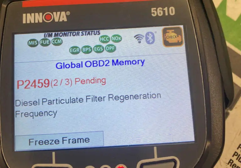
(Credit: Cumminsforum.com)
The PCM monitors the DPF regeneration process and exhaust pressure to ensure optimal performance. It will trigger the P2459 code under two specific circumstances:
- First, if the exhaust pressure fails to reach the required level
- Second, if the passive regeneration process (typically in a passive DPF system) does not adhere to the programmed frequency.
As I mentioned above, the DTC P2459 is exclusive to diesel-powered vehicles, encompassing both passenger cars and trucks that utilize diesel engines. Models from various manufacturers can experience this issue, including brands such as Ford, Chevrolet, Dodge, and more. There are some engines familiar with this code, including Duramax engines or 6.7 Cummins, etc.
How Severe Is The P2459 Code?
The severity of the P2459 code is considered moderate. While the code itself doesn’t indicate an immediate safety threat, it signifies a malfunction in the DPF regeneration process.
So can you still drive with the P2459? – The answer is Yes – However, it’s important to note that when this code is triggered, your vehicle might go into limp mode. In this mode, the engine’s power and performance might be limited to prevent further damage.
While you can drive your vehicle in this condition for short distances, it’s not a recommended long-term solution. In this case, it’s necessary to have the issue diagnosed by a qualified mechanic.
What Are The Symptoms Of The P2459 Code On Diesel Vehicles?
The presence of DTC P2459 can manifest through several noticeable symptoms, including:
- Illuminated warning lights ON (MIL and/or DPF light)
- Vehicle stuck in reduced performance mode (limp mode)
- Impaired acceleration
- Engine-related issues
What Causes The P2459 Code?
There are multiple factors can trigger the P2459 code, such as:
- Malfunctioning DPF pressure sensor
- Restricted DPF or exhaust system
- Accumulated soot within the DPF
- Electrical circuit problems
- Faulty fuel system
- Damaged diesel oxidation catalyst (DOC)/DPF filter
- Air leaks
- Bad fuel filters
- PCM-related concerns
Read more: Ford OBD2 Codes List for FREE Download
How To Diagnose And Fix The P2459 Code On Your Vehicles?
When faced with Diagnostic Trouble Code (DTC) P2459, it’s important to follow a systematic approach for diagnosis and repair. Below are the essential tools and parts, a step-by-step procedure, and an estimation of repair costs to assist in resolving the issue.
Essential Tools And Parts
To diagnose and repair the P145C code effectively, ensure you have the following tools and parts at hand:
- OBD-II scanner
- Digital multimeter
- DPF pressure sensor
- DPF cleaning kit (if necessary)
- Replacement parts based on diagnosis
Step-by-Step Procedure
1. Check The DPF Pressure Sensor
- Locate the DPF pressure sensor (consult your vehicle’s repair manual if needed).
- Disconnect the electrical connector from the sensor.
- Use a digital multimeter to measure the sensor’s resistance and compare it to the specifications in the repair manual.
- If the resistance is out of range, replace the DPF pressure sensor with a new one.
2. Visually Inspect The Restricted DPF Or Exhaust System
- Inspect the exhaust system and DPF for visible blockages or damage.
- If no visible issues are found, perform a back pressure test to measure exhaust flow.
- Compare the measured back pressure to the manufacturer’s specifications.
- If the back pressure is too high, consider cleaning or replacing the DPF or exhaust components as needed.
3. Check The Accumulation Of Soot Within The DPF
- Perform a forced DPF regeneration as recommended in your vehicle’s manual. This may involve driving at a certain speed or RPM range for a specified duration.
- If forced regeneration doesn’t resolve the issue, consider using a DPF cleaning additive or a professional DPF cleaning service.
4. Examine Wiring Harnesses And Connectors
- Check all wiring and connectors related to the DPF pressure sensor and other relevant components.
- Repair any damaged wires or connectors and ensure proper connections.
5. Inspect The Fuel System For Clogging Or Damage
- Inspect the fuel system components, including fuel filters, fuel lines, and injectors.
- Replace any faulty or clogged fuel filters and ensure proper fuel flow to the engine.
6. Examine The DOC Or DPF Filters
- Inspect the DOC/DPF filter for physical damage or cracks.
- If damage is evident, replace the damaged component with a new one.
7. Check For Any Air Leaks In The Exhaust System
- Carefully inspect the entire exhaust system for any leaks or gaps.
- Use exhaust sealant or gaskets to seal any identified leaks.
8. Test The Performance Of The PCM
- Perform a thorough scan of the PCM using a diagnostic tool to identify any related faults.
- If PCM-related issues are found, consult the vehicle’s repair manual or seek professional assistance for appropriate diagnosis and repair.
9. Clear The Codes And Test Drive
After conducting all procedures, clear the codes by using an OBD scanner. Perform a test drive to see if the codes come back or not.
Note: It’s important to consult your vehicle’s repair manual or seek professional assistance if you’re unsure about any step in the process.
Read more: Honda OBD2 Codes List [Generic + Manufacturer-specific]
DIY Repair Level And Estimated Costs
When it comes to addressing Code P2459 and related issues, there are steps you can take on your own to diagnose and potentially fix the problem. However, the level of DIY repair varies based on your mechanical skills, tools, and comfort level. If you’re experienced and confident, you might successfully complete tasks like inspecting for visible blockages, checking wiring, or performing basic checks. For more complex tasks, it’s advisable to consult a professional mechanic.
Here’s an estimated cost breakdown for main repair tasks:
| Repair Task | Estimated Cost |
| DPF pressure sensor replacement | $50 – $150 |
| Exhaust system inspection and repair | $50 – $300 |
| Professional DPF cleaning service | $150 – $500 |
| Diesel Oxidation Catalyst (DOC)/DPF replacement | $200 – $800 |
| PCM software update or replacement | $100 – $1,500 |
Keep in mind that these costs are approximate and can vary based on vehicle make, model, and location. If you’re uncertain or encounter challenges during the repair process, don’t hesitate to seek help from a qualified mechanic to ensure the job is done correctly and safely.
P2459 Infographic
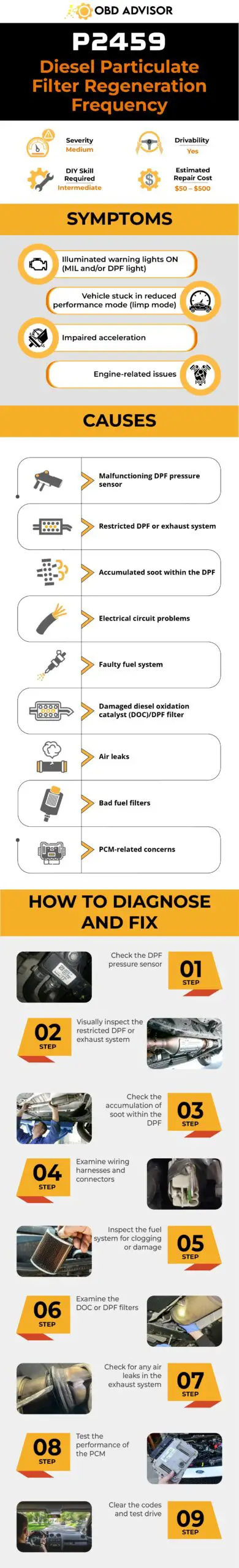
Final Thoughts
Facing the P2459 code might seem daunting, but armed with knowledge and guidance, you’re well-equipped to address the issue. Remember, proper diagnosis and timely repairs are essential for maintaining optimal vehicle performance and minimizing emissions. Whether you’re a seasoned DIY enthusiast or prefer leaving it to the experts, taking action now ensures a smoother ride ahead.
If you found this guide helpful, share it with fellow vehicle owners who might benefit. Feel free to leave your comments and questions below – we’re here to assist you on your automotive journey. Safe travels and happy troubleshooting!
Find more codes by using our OBD lookup tool!
Reference Sources
- JustAnswer, P2459 Diagnostic Procedure [PDF document]
- Wikipedia, Diesel particulate filter
- Mr Tyre, Limp Mode Causes and What to Do About It. Mr Tyre
P1449 BMW Code: What To Do When Encountering It
P1449 BMW Code: What To Do When Encountering It
Modern vehicles have advanced diagnostic systems that monitor various components for optimal performance. When a fault is detected, a specific error code is generated to aid technicians in identifying and resolving the issue. In the case of BMW vehicles, one common trouble code is P1449, which is specifically related to the DMTL (Diagnostic Module Tank Leakage) pump.
This article aims to shed light on BMW Code P1449, its symptoms, potential causes, and possible solutions. Moreover, by understanding the underlying factors contributing to this fault code, BMW owners and technicians can effectively diagnose and resolve the issue.
Let’s get started!
P1449 BMW: A Quick Overview
Look over the summary for the BMW P1449 code below!
- Definition: Diagnostic Module Tank Leakage Pump Current Too High
- Severity: Medium
- DIY Skill Level: Intermediate
- Continue To Drive?: Yes
- Estimated Repair Cost: $50 – $400
What Does The P1449 BMW Code Mean?
The BMW code P1449 indicates a fault within the vehicle’s evaporative emission control system, specifically related to the DMTL (Diagnostic Module Tank Leakage) pump. The evaporative emission control system is designed to prevent the release of harmful fuel vapors into the atmosphere, ensuring environmental compliance.
When the DMTL pump malfunctions or fails to operate as intended, it can trigger the P1449 error code. The DMTL pump is responsible for monitoring the fuel tank for leaks and maintaining the proper pressure within the evaporative emission system. Consequently, if the pump detects a leak or a pressure deviation, it signals the vehicle’s engine control module (ECM) and triggers the P1449 code.
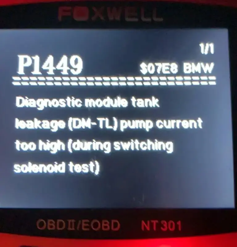
Several BMW models are commonly associated with the P1449 code, including the BMW 3 Series, BMW 5 Series, BMW 7 Series, BMW X3, BMW X5, etc. In some cases, the P1449 code may be accompanied by additional codes, which can provide further insights into the specific issue.
Common accompanying codes related to the DMTL pump and evaporative emission control system, include P1447, P0442, P0455, and P0456. These accompanying codes help technicians narrow down the potential causes and pinpoint the specific area of concern within the evaporative emission control system.
How Severe Is The P1449 Code In BMW?
The severity of BMW Code P1449 can be considered moderate. While this fault code indicates a problem within the evaporative emission control system, it typically does not pose an immediate safety risk or cause drivability issues. However, it is important not to overlook or ignore this code.
It is generally okay to continue driving with this code in the short term. Still, to ensure that the vehicle complies with environmental regulations and the evaporative emission control system functions properly, it is recommended to address the P1449 code promptly.
What Are The Signs Of The P1449 BMW Code?
When a BMW vehicle experiences the P1449 code, the following symptoms may be observed:
- Check Engine Light (CEL) illuminated
- Fuel odor
- Difficulty starting the engine
- Decreased fuel efficiency
What Causes The P1449 Code In BMW Vehicles?
The P1449 code in BMW vehicles can be caused by various factors, including:
- Overfill the fuel tank
- Damaged DMTL wiring harness
- Malfunctioning DMTL pump
- Leaks or cracks in the fuel vapor lines
Repair And Diagnosis Of BMW Code P1449
This section provides a guide to diagnose and repair the P1449 code in BMW vehicles. It includes the necessary tools and parts, a step-by-step procedure, and information on DIY repair level and estimated costs. However, if you are unsure or lack experience, it is recommended to consult a professional mechanic or BMW dealership for accurate diagnosis and resolution.
Essential Tools And Parts
In order to effectively identify and rectify the C1109 code in Nissan vehicle, you will need the subsequent tools and components:
Step-by-Step Procedure
1. Code retrieval
Use an OBD-II scanner to retrieve the P1449 code and any accompanying codes.
2. Check for blown fuses
- Inspect the fuses related to the evaporative emission control system.
- Replace any blown fuses, as they may indicate a bad DMTL pump or a broken wire shorted to ground.
3. Inspect for vacuum leaks
- Check the fuel vapor lines for vacuum leaks.
- Look for cracked or disconnected hoses, loose fittings, or damaged connectors.
4. Replace OEM gas cap (if applicable)
- If your BMW has the “green” OEM gas cap, replace it with the blue gas cap.
- The blue cap provides a tighter seal and may help resolve the issue.
5. Check the DMTL pump
- Test the DMTL pump’s functionality using a multimeter.
- Assess the pump’s functionality and determine if it needs replacement.
- Ensure the rubber grommet on the old pump is used when reinstalling the pump.
6. Clear the code and test drive
- Once repairs are made, use the OBD-II scanner to clear the BMW C1449 code and any associated trouble codes.
- Take the vehicle for a test drive to verify if the car’s performance is back on track or not.
Note:
- The DMTL pump is usually located at the rear right side of the vehicle, positioned behind the wheel well liner. To find the exact location of the DMTL pump, it is advisable to refer to the manual.
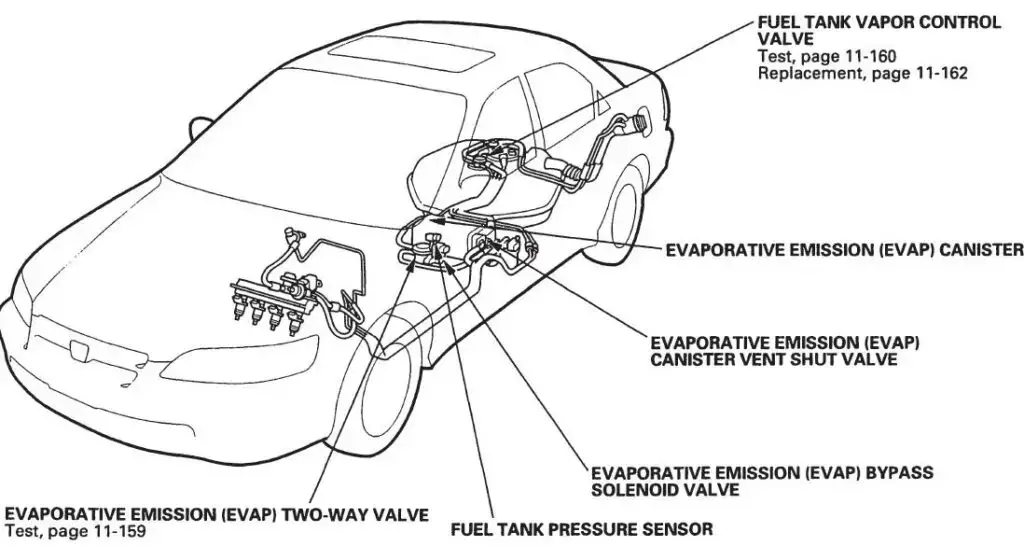
Read more: BMW Fault Codes: FREE Comprehensive OBD1 And OBD2 Codes List
DIY Repair Level And Estimated Costs
Repairing the P1449 code demands intermediate to advanced DIY skills. If you’re confident in your experience with electrical and fuel systems, you can proceed. However, if you’re uncertain or lack relevant experience, it’s recommended to consult an expert mechanic or BMW dealership. They are equipped with specialized knowledge, tools, and resources for proper diagnosis and repair.
Estimated costs for the main repair tasks associated with the P1449 code may vary depending on factors such as the BMW model, location, and source of parts. Here is a table listing approximate costs:
| Repair Task | Estimated Cost |
| Wiring and connector repair | $50 – $150 |
| Gas cap replacement | $30 – $70 |
| DMTL pump replacement | $200 – $500 |
Please note that these are rough estimates, and actual costs may differ. Consult a trusted mechanic or BMW dealership for accurate pricing and to ensure the use of genuine replacement parts. Remember, prioritizing safety and accuracy is crucial when dealing with complex automotive repairs.
Final Thoughts
Ready to conquer the P1449 code in your BMW? With the insights gained, you’re now equipped to diagnose and resolve the issue confidently. Moreover, don’t keep this knowledge to yourself – share it with fellow BMW enthusiasts who may be facing similar challenges.
If you have questions or success stories, we’re all ears in the comments section below. Furthermore, to keep your BMW running smoothly, stay tuned for more expert automotive guides. Hit the road with confidence!
Reference Sources
- New York State Department of Motor Vehicles, Evaporative Emission Control System (EVAP)
- RepairSmith, Why Does My Car Smell Like Gasoline?
P0420: Catalyst System Efficiency Below Threshold (Bank 1)
P0420: Catalyst System Efficiency Below Threshold (Bank 1)
Did your car scanner throw the P0420 code? Are you confused about which decision to make and whether to keep driving?
Continue reading to briefly evaluate your current situation.
- P0420 Definition: Catalyst System Efficiency Below Threshold (Bank 1).
- Code Type: Generic – P0420 indicates the same problem whether you’re having a Chevy, Honda, or Nissan, etc.
- Can I drive with the P0420 code? Yes, but doing so will further damage your catalytic converter.
- Easy to fix? Intermediate to advanced level.
- Cost: $400 – $2200 (common).
Now you know that the P0420 code may not imply immediate danger.
To avoid wasting time and money on finding the problem, let’s dive into four causes of the P0420 code and their corresponding solutions.
What Does the P0420 Code Mean?
The P0420 is the diagnostic code for a defective or underperforming catalytic converter. However, this code may pop up due to other reasons not directly related to the converter.
What Is The Catalytic Converter’s Function?
To protect the environment, the catalytic converter limits and breaks down the harmful exhaust gasses (e.g., Carbon Monoxide and Nitrogen Oxide) from internal combustion engines.
How Do You Know Your Catalyst System Is Below Efficiency?
There are two oxygen sensors sitting near the converter, one at the front (upstream) and another at the rear (downstream).
The upstream sensor measures the O2 level of exhaust fumes exiting the engine. Meanwhile, the downstream sensor checks the O2 level of gasses leaving the converter.
In normal conditions, the data from the upstream sensor will fluctuate while the downstream’s must remain steady. If both sensors output the same data, the catalyst system is inefficient, harmful gasses will be released into the environment, and P0420 is set.
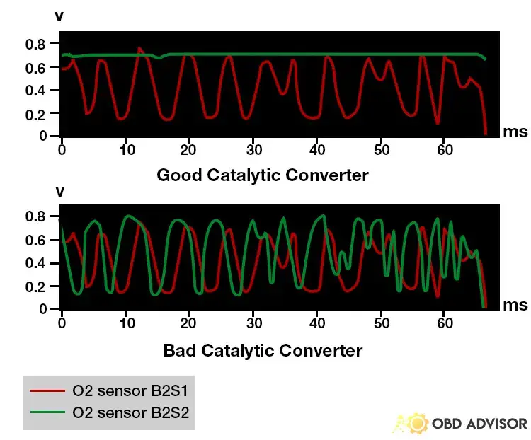
The P0420 code may not seem serious enough to stop driving. However, the catalyst system may be further damaged, and the car will fail emission tests.
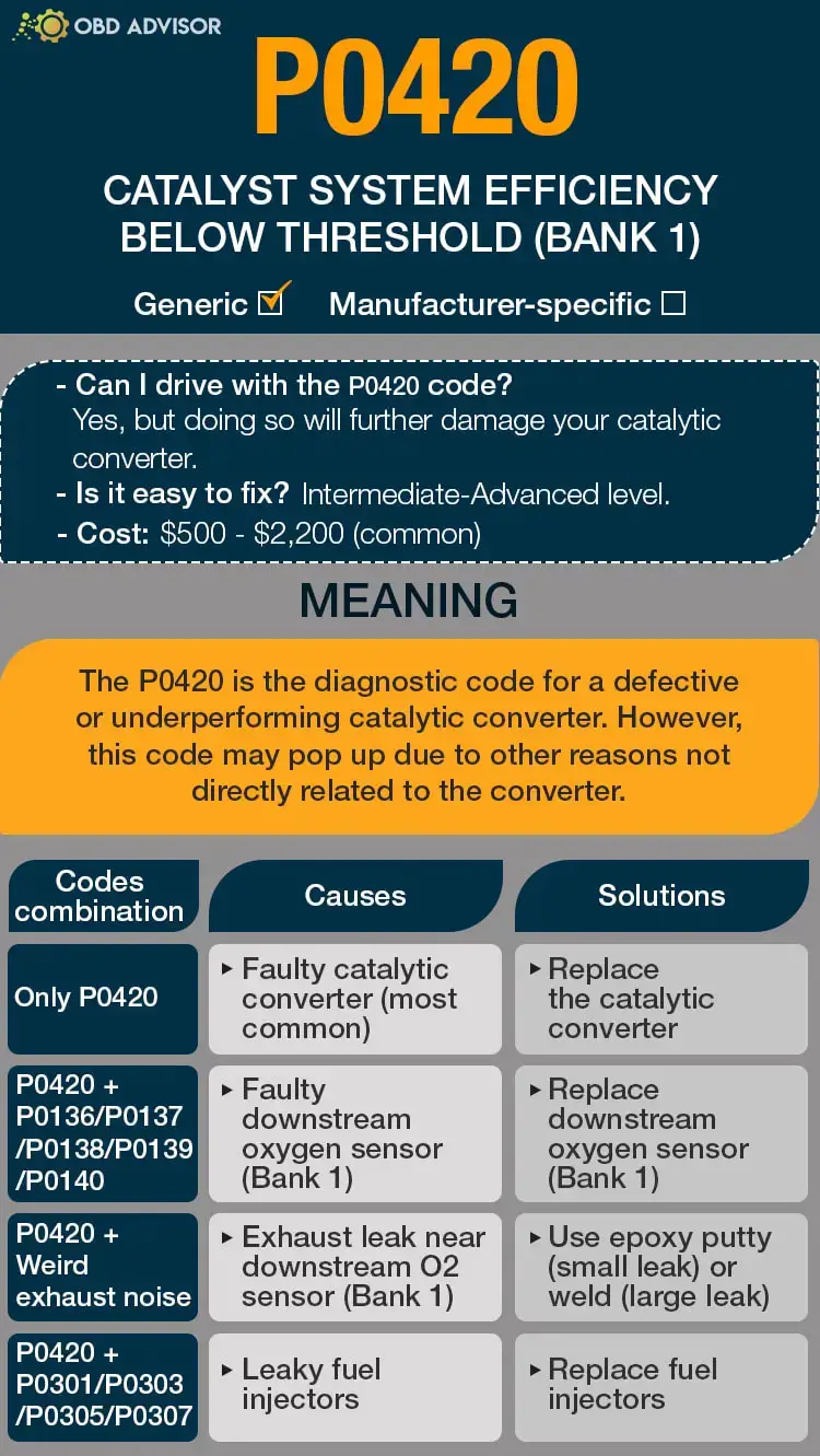
P0420 Causes Identification: Quick View
A faulty catalytic converter is often the culprit when a scanner indicates the P0420 code. However, the downstream oxygen sensor or a failing engine component may be the root cause. Hence, another code may show up with the P0420.
Below are the likely causes of this code and their possible solutions.
| Codes Combination | Causes | Solutions |
|---|---|---|
| Only P0420 | Faulty catalytic converter (most common) | Replace the catalytic converter |
| P0420 + P0136/P0137/P0138/P0139/P0140 | Faulty downstream oxygen sensor (Bank 1) | Replace downstream oxygen sensor (Bank 1) |
| P0420 + Weird exhaust noise | Exhaust leak near downstream O2 sensor (Bank 1) | Use epoxy putty (small leak) or weld (large leak) |
| P0420 + P0301/P0303/P0305/P0307 | Leaky fuel injectors | Replace fuel injectors |
Note: The causes for each code combination are the most common ones. There can be some uncommon issues hidden under those codes.
P0420: Causes, Symptoms, And How to Fix
If a vehicle outputs the P0420 diagnostic code after scanning, the following might be the cause.
Cause #1: Faulty Catalytic Converter
A faulty catalytic converter is the most common cause of the P0420 code. Sometimes, this might be due to:
- Structural damage caused by thermal shocks
- Weak welding points
- Direct hits from rocks and debris
- Unburnt fuel coats the catalyst
In any case, a faulty catalytic converter fails to convert exhaust fumes to environmental-friendly gasses.
Therefore, the exhaust fumes exit from the catalytic converter without any changes (filtering or cleaning). As a result, the upstream and downstream oxygen sensors’ reading will be the same, triggering P0420.
Look out for the following symptoms to identify a fault catalytic converter.
- Check engine light
- Dark exhaust smoke
- Gasoline smell around the car
- Excess heat under the car
- Poor engine performance
The chances of restoring the catalytic converter to its initial condition are slim. A suitable replacement is the best solution though it is pricey.
Cause #2: Faulty Downstream Oxygen Sensor
The downstream oxygen sensor’s function is to keep track of the catalytic converter’s efficiency. If the sensor fails, it may tell the PCM that the catalytic converter is underperforming (in fact, it isn’t.)
There are no obvious symptoms of a faulty downstream oxygen sensor. You can conduct an O2 sensor test to determine whether it is faulty or not.
If it is your problem, your scan tool will trigger only P0420 or with other codes like P0136, P0137, P0138, P0139, and P0140.
The most realistic solution is to replace the oxygen sensor. Buying the part and changing it yourself will save you money from the repair shop.
Cause #3: Exhaust Leak Near Downstream O2 Sensor
The exhaust leak affecting the output voltage can be found near the downstream oxygen sensor.
The exhaust system can suck oxygen into the exhaust flow through a leak due to the pressure differences. Consequently, the sensors will capture incorrect readings due to the extra oxygen, causing the PCM to set P0420.
The following are the common symptoms of an exhaust leak:
- Unusual blowing noise from underneath the car
- Low engine performance
- Unpleasant odor around the car during operation
In the case of small leaks, epoxy glue will resolve the issue. However, some larger leaks may require welding.
Cause #4: Leaky Fuel Injectors
Leaky fuel injectors can also be the root cause of the P0420 code. When the fuel injector leaks, excess fuel in liquid form reaches the combustion chamber.
As a result, some amount of fuel is left unburnt and passed to the exhaust system. Over time, the waste fuel builds up and overloads the catalyst system, reducing its efficiency drastically.
The following symptoms can mean that a car has leaky fuel injectors.
- Gasoline smell in and around the car
- Rough engine performance and idling
- Increased fuel consumption
- Heavy exhaust fumes
- Excessive heat under the car
The only way to resolve the problem is to replace the leaky fuel injectors with suitable ones.
How Much Does It Cost to Fix P0420?
The cost of resolving the P0420 depends on the root cause of the problem. A fault catalytic converter is the most common cause which costs $400 – $2,000 to repair yourself. If it is too difficult to handle this job, you will pay $500 – $2200 to visit a mechanic.
The following are the possible costs of fixing the P0420.
The Estimated Repair Cost Of P0420
| Solutions | Cost |
|---|---|
| Replace the catalytic converter | DIY: $400 – $2000 Repair shop: $500 – $2200 |
| Replace downstream oxygen sensor (Bank 1) | DIY: $20 – $95 Repair shop: $100 – $450 |
| Use epoxy putty (small leak) | DIY: under $10 Repair shop: not recommended |
| Weld the leak (large leak) | DIY: not recommended Repair shop: $30 – $100 |
| Replace fuel injectors | DIY: $400 – $900 Repair shop: $600 – $1,200 |
Note: The data in this table was collected in June 2022. The actual price depends on many factors, such as your car’s make and year, mechanic’s rate, etc.
You Ask, I Answer
Once the catalytic converter fails or underperforms, the car’s computer transmits the P0420 and related diagnostic codes.
By now, you should be able to understand the likely causes of the code and decide how to fix them.
Do you have questions or comments regarding the P0420 code? Please reach out to us using the comment section.
See ya!
Read more: The 9 Best OBD2 Scanners for 2024: The Only Review You Need
P0101 – Mass or Volume Air Flow “A” Circuit Range/Performance
P0101 – Mass or Volume Air Flow “A” Circuit Range/Performance
The P0101 OBD2 code indicates a problem with your mass air flow circuit. Proper air flow is key to your engine’s operation, and the MAF sensor helps to regulate it. When it has a problem, it can make your system run rough and reduce your gas mileage.
There are a couple of primary sources of the P0101 trouble code. It could mean there’s a vacuum leak somewhere in your exhaust system. It could also indicate a problem with the MAF sensor itself. The good news is, it’s relatively easy to find the source of the code if you follow the diagnostic process outlined below.
P0101 Code Definition
P0101 Code Definition (Generic): Mass air flow (MAF) circuit range/performance
P0101 Audi Code Definition: Mass or volume air flow circuit range/performance problem
P0101 Duramax Code Definition: MAF/VAF sensor range/performance problem
P0101 Mercedes Code Definition: Mass or volume air flow circuit range/performance problem
P0101 Nissan Code Definition: Mass Air Flow (MAF) (very common, service bulletin exists)
P0101 Toyota Code Definition: Mass air flow circuit range/performance
P0101 VW Code Definition: Mass or volume air flow circuit range/performance problem
What Does P0101 Mean?
The P0101 OBD2 code tells you the amount of air entering the engine is out of your engine’s specified range. The air flow into the engine is measured by the mass air flow (MAF) sensor. It sends this information to the engine control unit (ECU) to help manage the engine.
When the air flow reported by the MAF sensor is outside your system’s acceptable range, the P0101 trouble code activates. Issues with the air flow also reduce your engine’s performance and can make your car drive erratically.
The MAF sensor is mounted in the engine air intake tract for your vehicle, downstream from your air filter. It measures the air’s density and volume being pulled into the engine by sampling a portion of the air. From this data, it extrapolates the conditions in the total air mass. Some MAF sensors also have an air temperature circuit, which could also contribute to the air flow problems.
Many systems can be the root cause of this trouble code. Your system could have a vacuum leak or other mechanical issue that allows too much air into the engine. It could also be a malfunction of the sensor itself. A full diagnosis is the best way to track down and fix the problem.
What Are The Symptoms Of The P0101 Code?
You will likely notice drivability problems if there is too much air going into your engine. These symptoms include:
- Illumination of the check engine light
- Stalling engine
- Black smoke in the exhaust
- Rough starts or idling
- Low engine power
- Decreased fuel economy
What Are The Causes Of P0101?
- MAF sensor is dirty or faulty
- Damaged or faulty wires on the MAF sensor
- Damaged air intake boot
- Clogged air filter
- Leaks in the air intake system
- Clogged catalytic converter (most common on Chevrolets and GMCs)
How Serious Is The P0101 Code?
The P0101 code is moderately severe. While it’s not dangerous to drive your car with this code active, sustained driving can damage the engine. You should repair this trouble code as soon as possible.
How To Diagnose The P0101 Code

You may find technical service bulletins for this trouble code related to your vehicle’s make or model. Check before you start your diagnosis, as this can save you some time in isolating the problem.
Tools You’ll Need:
Method:
- Scan your system for other related trouble codes, especially P0100-P0104, which indicate other issues with the air flow. If these codes are present, diagnose them first.
- Read the real-time data for the oxygen sensors and MAF sensor to check their operation.
- Open the air intake box and check the air filter. Make sure it’s installed properly, and replace it if it’s clogged or dirty.
- Remove the air intake snorkel. Check it for damage, and inspect the MAF sensor. While you’re at it, check the wiring around the harness for damage or loose connections. Replace the air intake snorkel if necessary.
- Check the air intake system for leaks. You can visually inspect the hoses, running your fingers down them to check for hidden weak spots and cracks. Also, make sure they’re securely attached.
- Run an exhaust back pressure test to check for clogs in the catalytic converter. Clean it using a catalytic converter cleaner, following the instructions on the bottle.
Common Mistakes To Avoid While Diagnosing The P0101 Code
While the MAF sensor can cause the P0101 trouble code, it’s not always the problem. Make sure you check for clogs and leaks throughout your system before you replace the sensor.
What Should You Do To Fix The Code P0101?
The steps you take to diagnose P0101 may clear it, as well. Clear the codes and take a test drive. If the code comes back, follow the steps below:
- Replace any damaged wires or leaking hoses found in your diagnosis.
- Clean your MAF sensor. This sensor is very sensitive, so only use cleaners specifically designed for mass air flow sensors. Spray each side of the sensor for 3-5 seconds, wait 10 seconds, then spray again. You don’t need to wipe it off.
- Clear the codes and test drive your car to see if the code comes back. If it does, replace the MAF sensor. Make sure you use an OEM component, not an after-market product. Incompatible MAF sensors can lead to further problems with your system.
- If there is mesh in your air intake system (mostly Volkswagen vehicles), inspect it for dirt and damage. Clean or replace it as necessary.
- Check the operation of the catalytic converter. If it’s still failing after cleaning it, replace it.
Tips To Avoid P0101 In The Future
Dirt and build-up in your engine can cause many problems, and the P0101 trouble code is among them. Check your air filter regularly, and make sure it’s correctly installed when you replace it. Regular maintenance of your engine’s fluids, especially the oil, will also help keep your engine clean.
Frayed wires can also trigger this code. Make sure all the wires in your system are kept clear of ignition coils and other potential sources of damage.
Read more: P0012 Code: Meaning, Symptoms, Causes, And Fixes
P0118: Engine Coolant Temperature Sensor Circuit High Input
P0118: Engine Coolant Temperature Sensor Circuit High Input
Suppose you are driving down the road, and your check engine light turns on, displaying a P0118 code error!
Well, you read that using an OBD scanner, but what next?
Let’s discuss your situation in this article.
- P0118 Definition: Engine coolant temperature sensor circuit high input problem.
- Code type: Generic – P0118 indicates the same problem whether you’re having a Chevy, Honda, Dodge, etc.
- Can I drive with the P0118 code? Yes, you can. However, it may cause damage to your engine in the long term.
- It is easy to fix? DIY to advanced levels.
- Cost: $85 – $170 (common).
To help you understand the P0118 code, I have split this article into four parts: causes, symptoms, how to diagnose, and how to fix the P0118 code.
Read further and unveil everything you need to know about the P0118 and its quick fixes.
What Does the P0118 Code Mean?
The P0118 code stands for “Engine Coolant Temperature (ECT) Sensor Circuit High Input”. The code is triggered when PCM recognizes that the input voltage of the ECT is more than 5V.
The ECT sensor measures the engine coolant temperature. This data is sent to the powertrain control module (PCM) to control the cooling system.
Under good conditions, the higher the temperature, the lower the ECT sensor voltage. This number ranges from 0.5 to 4.5V.
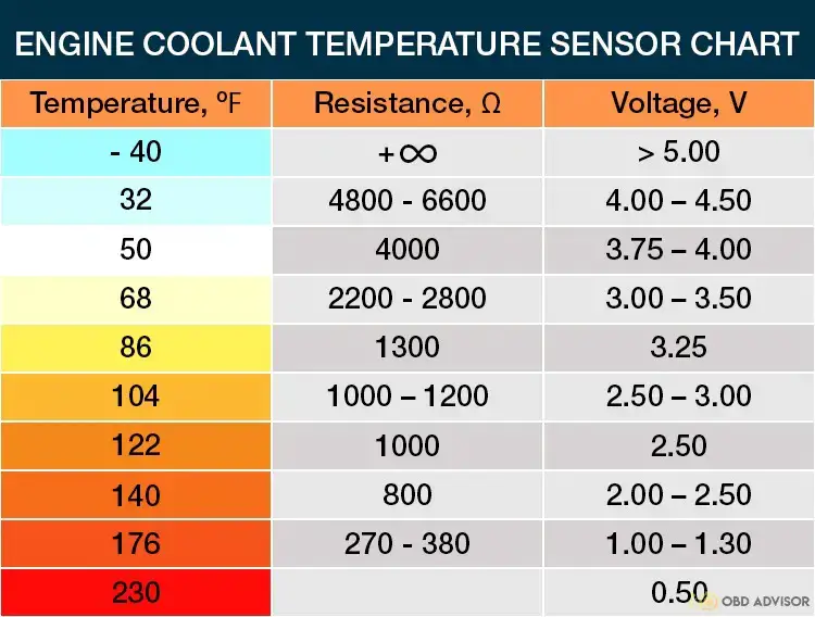
As mentioned above, the code P0118 is set when the ECT voltage is higher than 5V. This means the PCM is receiving a “too cold” signal (-40F). Of course, the PCM knows this signal is abnormal and does not believe in it (if it did, the thermostat would close, leading to an overheating engine.)
As a result, P0118 makes your car enter failsafe mode to prevent the engine from overheating.
In this mode, the cooling system is allowed to run at maximum capacity, which includes:
- Radiator constantly running.
- Wide-open thermostat.
- AC off.
Consequently, the car takes more time to warm up. This reduces fuel economy and damages the engine parts in the long run.
Other codes may appear with P0118: P0115, P0116, P0117, and P0119.
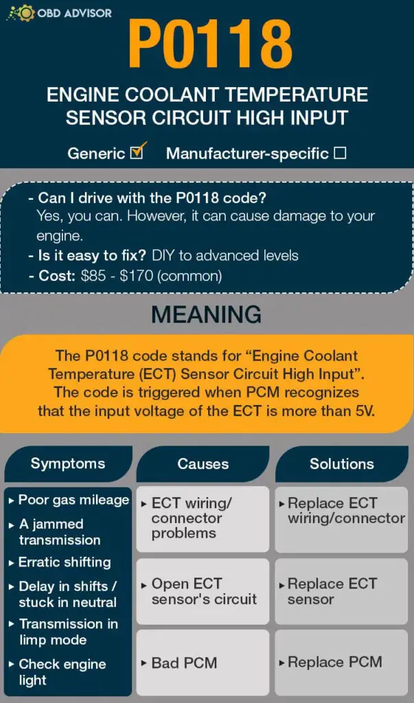
P0118: Causes, Symptoms, and How To Fix
Causes #1: ECT Wiring/Connector Problems
In many cases, P0118 is caused by the ECT sensor connection problems in the wiring harness or inside the connectors.
The symptoms of this problem are shown by:
- Erratic temperature gauge readings.
- Malfunctioning air conditioner.
- Radiator fans running constantly.
- High fuel consumption.
- Hard start.
- Check engine light on.
- Black smoke from the engine.
- Poor idling.
If this is the case, repairing the wiring harness will fix the problem.
Causes #2: Open ECT Sensor’s Circuit
If the wiring is fine, the circuit inside the ECT sensor can be open for various reasons, which leads to the P0118 popping up.
The symptoms of a bad ECT sensor are the same as the ECT wiring/connector causes.
In this case, replacing the ECT will fix the P0118.
Read more: P0172: System Too Rich (Bank 1)
Causes #3: Faulty PCM (Rare)
The powertrain control module (PCM) is the main engine computer that ensures your engine transmission works effectively. So, a faulty PCM can be a potential cause of the P0118 code, although it rarely occurs.
Also, there are combination codes with P0115 and P0117 associated with faulty PCM in some cases.
You can repair faulty PCM by reprogramming it, although that won’t be effective in the long run.
So, replacing the PCM would be the best option.
P0118 Causes Identification: How to Diagnose
As mentioned above, in most cases, there are 2 main causes triggering the P0118 code:
- The ECT wiring harness.
- The ECT sensor itself.
The question is: “Which one?”
Continue reading to reveal how you can diagnose the cause of the P0118 code.
Diagnosing ECT Wiring/Connector Problems
First, locate the sensor and visually inspect its wiring to check if there are any burnt, broken, or unplugged wires and fix them.
If there isn’t, use a multimeter to check the wiring harness. Here are the steps to do so:
- Unplug the cables connecting the sensor.
- Turn on your vehicle’s ignition key without starting the engine.
- Connect the multimeter red clip to the positive terminal and the black clip to the ground wire.
- Record the multimeter readings. Your sensor wiring has a problem if your multimeter registers a zero ohm reading. Slightly more than zero ohms multimeter reading should be good wiring.
Diagnosing Open ECT Sensor’s Circuit
If all the wires are good, the ECT itself is very likely to be the problem.
Here’s how you can test it:
- Locate the ECT sensor: near the thermostat in the cylinder head or block or on the thermostat housing.
- Remove the sensor wiring connectors while the engine ignition is off.
- Connect an ohmmeter between the sensor terminals. Measure and record the resistance.
If the ohms reading is more than 6600Ω or infinity, the sensor’s circuit is open and needs a replacement.
Diagnosing Faulty PCM
After testing the ECT sensor and circuit problems and there aren’t any problems with these, a bad PCM should be the last conclusion.
However, this is a rare cause.
Having a mechanic handle it is the best solution in this case. And it’s not cheap!
How Much Does It Cost to Fix the Code P0118?
Most P0118 causes can be fixed by yourself with a few bucks.
For example, the ECT sensor can cost you $10 to $30.
Most Auto shops charge the cost of fixing code P0118 in terms of the hours for the work.
Although the charges vary from shop to shop, you can expect to spend between $85 and $170, excluding the cost of the parts.
The estimated repair cost of the P0118
| Solutions | Repair cost |
|---|---|
| Repairing ECT wiring / connector problems | DIY: a few bucks Mechanic: $85 to $170 |
| Replacing malfunctioning ECT sensor | DIY: $10 to $30 Mechanic: $85 to $170 |
| Replacing faulty PCM | DIY: Not recommended Mechanic: $1000 to $3000 |
Note: The data in this table is dated June 2022. The exact cost will depend on various factors such as mechanic rates, car model, etc.
You Ask, I Answer
Hopefully, this article explains why you are getting the P0118 and how you can find the best solution that saves you money.
If you have any other concerns about the P0118 code, don’t hesitate to comment below, and I will be quick to answer.
Also, you can help someone by sharing what you did in case you had this code before.
Let’s all have a safe and risk-free drive!
Read more: The 9 Best OBD2 Scanners for 2024: The Only Review You Need
Subaru Fault Codes List: Your Complete Resource For Diagnosis
Subaru Fault Codes List: Your Complete Resource For Diagnosis
Are you tired of feeling perplexed by those cryptic fault codes that appear on your Subaru’s diagnostic system? Do you find yourself asking questions like “What does this code mean?”.
Fear not. Our comprehensive Subaru fault codes list is here to provide the answers you seek.
Whether you’re a Subaru enthusiast or a DIY mechanic, this guide is your key to unlocking the secrets behind those enigmatic numbers. We’ll walk you through the OBD1 and OBD2 codes, equipping you with the knowledge and confidence to diagnose.
So, let’s get started!
Subaru OBD1 Codes List and Definition [Free Download]
Free download: Full Subaru OBD1 Trouble Codes List and Meaning PDF
Note: Use the search box in the table below to quickly find the specific code you’re looking for.
| Code | Definition |
|---|---|
| Code 11 | Crankshaft Position Sensor |
| Code 12 | Starter Signal |
| Code 13 | Camshaft Position Sensor |
| Code 18 | Electrical Load Signal |
| Code 21 | Engine Coolant Temperature Sensor |
| Code 22 | Knock Sensor |
| Code 23 | Mass Air Flow Sensor Circuit |
| Code 24 | Idle Control System Malfunction |
| Code 26 | Intake Air Temperature Sensor |
| Code 28 | Knock Sensor #2 |
| Code 29 | Crankshaft Position Sensor 2 |
| Code 31 | Throttle Position Sensor Circuit |
| Code 32 | Oxygen Sensor |
| Code 33 | Vehicle Speed Sensor |
| Code 35 | CPC System |
| Code 37 | Rear O2 Sensor Circuit / A/F Sensor Circuit Malfunction |
| Code 38 | Torque Permission Signal |
| Code 38 | Torque Control Signal #2 |
| Code 38 | Torque Control Signal #1 |
| Code 39 | Traction Control System |
| Code 42 | Idle Switch |
| Code 43 | Accelerator Pedal Switch |
| Code 44 | Turbo charging Pressure Control Signal |
| Code 45 | Pressure Sensor |
| Code 48 | Lean Burn System |
| Code 49 | CO Resistor |
| Code 51 | Neutral Position Switch |
| Code 53 | Anti-Quick Operation Mode |
| Code 53 | IMM Control Module EEPROM |
| Code 53 | EGI Control Module EEPROM |
| Code 53 | Use of Unregistered Key |
| Code 53 | Key Communication Failure |
| Code 53 | Communication Error (Time Over) |
| Code 53 | IMM Circuit Failure (Except Antenna Circuit) |
| Code 53 | Reference Code Incompatibility |
| Code 53 | Antenna |
| Code 54 | Air Intake System |
| Code 55 | EGR Valve Lift Sensor |
| Code 56 | EGR System |
| Code 61 | Air Suction Control Solenoid Valve |
| Code 62 | Exhaust Manifold Valve Negative Pressure Control Solenoid |
| Code 64 | Relief Valve Control Solenoid Valve 1 |
| Code 64 | Relief Valve Control Solenoid Valve 2 |
| Code 65 | Differential Pressure Sensor |
| Code 66 | Twin Turbocharger System (T) |
| Code 66 | Twin Turbocharger System (S) |
| Code 66 | Twin Turbocharger System (H) |
| Code 66 | Two Stage Twin Turbocharger System |
| Code 88 | Fuel Pump Circuit Malfunction |
| Code 89 | VVT Systems (R) |
Subaru OBD2 Codes List and Definition [FULL]
Free download: Full Nissan OBD2 Trouble Codes List and Meaning PDF
Our user-friendly list is divided into Powertrain, Network, Body, and Chassis, making it easy to locate the relevant codes for different systems.
Note: Use the search box in the table below to quickly find the specific code you’re looking for.
Powertrain (P) Codes List
| Code | Definition |
|---|---|
| P0011 | Camshaft Position System Performance (Bank 1) |
| P0021 | Camshaft Position System Performance (Bank 2) |
| P0031 | Ho2s Heater Control Circuit Low (Bank 1 Sensor 1) |
| P0032 | Ho2s Heater Control Circuit High (Bank 1 Sensor 1) |
| P0034 | Turbo Charger Bypass Valve Control Circuit Low |
| P0035 | Turbo Charger Bypass Valve Control Circuit High |
| P0037 | Ho2s Heater Control Circuit Low (Bank 1 Sensor 2) |
| P0038 | Ho2s Heater Control Circuit High (Bank 1 Sensor 2) |
| P0051 | Ho2s Heater Control Circuit Low (Bank 2 Sensor 1) |
| P0052 | Ho2s Heater Control Circuit High (Bank 2 Sensor 1) |
| P0065 | Air Assisted Injector Control Range/Performance |
| P0066 | Air Assisted Injector Control Circuit Or Circuit Low |
| P0067 | Air Assisted Injector Control Circuit High |
| P0101 | Mass Air Flow Sensor Circuit Range/Performance Problem (High Input) |
| P0102 | Mass Air Flow Sensor Circuit Low Input |
| P0103 | Mass Air Flow Sensor Circuit High Input |
| P0106 | Pressure Sensor Circuit Range/Performance Problem (Low Input) |
| P0106 | Manifold Pressure Sensor Circuit Range/Performance Problem (Low) |
| P0107 | Manifold Pressure Sensor Circuit Malfunction (Low Input) |
| P0108 | Manifold Pressure Sensor Circuit Malfunction (High Input) |
| P0109 | Intake Air Temperature Circuit Malfunction |
| P0111 | Intake Air Temperature Sensor Range/Performance Problem |
| P0112 | Intake Air Temperature Sensor Circuit Malfunction (Low Input) |
| P0113 | Intake Air Temperature Sensor Circuit Malfunction (High Input) |
| P0114 | Intake Air Temperature Circuit Intermittent |
| P0115 | Engine Coolant Temperature Circuit Malfunction |
| P0116 | Engine Coolant Temperature Circuit Range/Performance Problem |
| P0117 | Engine Coolant Temperature Sensor Circuit Low Input |
| P0118 | Engine Coolant Temperature Sensor Circuit High Input |
| P0119 | Engine Coolant Temperature Circuit Intermittent |
| P0120 | Throttle/Petal Position Sensor/Switch A Circuit Malfunction |
| P0121 | Throttle Position Sensor Circuit Range/Performance Problem (High Input) |
| P0122 | Throttle Position Sensor Circuit Low Input |
| P0123 | Throttle Position Sensor Circuit High Input |
| P0124 | Throttle/Petal Position Sensor/Switch A Circuit Intermittent |
| P0125 | Insufficient Coolant Temperature For Closed Loop Fuel Control |
| P0126 | Insufficient Coolant Temperature for Stable Operation |
| P0128 | Coolant Thermostat |
| P0130 | O2 Sensor Circuit (Bank 1 Sensor 1) |
| P0131 | O2 Sensor Circuit Low Voltage (Bank 1 Sensor 1) |
| P0132 | O2 Sensor Circuit High Voltage (Bank 1 Sensor 1) |
| P0133 | O2 Sensor Circuit Slow Response (Bank 1 Sensor 1) |
| P0134 | O2 Sensor Circuit No Activity Detected (Bank 1 Sensor 1) |
| P0135 | O2 Sensor Heater Circuit (Bank 1 Sensor 1 ) |
| P0136 | O2 Sensor Circuit (Bank 1 Sensor 2) |
| P0137 | O2 Sensor Circuit Low Voltage (Bank 1 Sensor 2) |
| P0138 | O2 Sensor Circuit High Voltage (Bank 1 Sensor 2) |
| P0139 | O2 Sensor Circuit Slow Response (Bank 1 Sensor 2) |
| P0140 | O2 Sensor Circuit No Activity Detected (Bank 1 Sensor 2) |
| P0141 | O2 Sensor Heater Circuit (Bank 1 Sensor 2 ) |
| P0142 | O2 Sensor Circuit Malfunction (Bank 1 Sensor 3) |
| P0143 | O2 Sensor Circuit Low Voltage (Bank 1 Sensor 3) |
| P0144 | O2 Sensor Circuit High Voltage (Bank 1 Sensor 3) |
| P0145 | O2 Sensor Circuit Slow Response (Bank 1 Sensor 3) |
| P0146 | O2 Sensor Circuit No Activity Detected (Bank 1 Sensor 3) |
| P0147 | O2 Sensor Heater Circuit Malfunction (Bank 1 Sensor 3) |
| P0151 | O2 Sensor Circuit Low Voltage (Bank 2 Sensor 1) |
| P0152 | O2 Sensor Circuit High Voltage (Bank 2 Sensor 1) |
| P0153 | O2 Sensor Circuit Slow Response (Bank 2 Sensor 1) |
| P0154 | O2 Sensor Circuit No Activity Detected (Bank 2 Sensor 1) |
| P0155 | O2 Sensor Heater Circuit Malfunction (Bank 2 Sensor 1) |
| P0156 | O2 Sensor Circuit Malfunction (Bank 2 Sensor 2) |
| P0157 | O2 Sensor Circuit Low Voltage (Bank 2 Sensor 2) |
| P0158 | O2 Sensor Circuit High Voltage (Bank 2 Sensor 2) |
| P0159 | O2 Sensor Circuit Slow Response (Bank 2 Sensor 2) |
| P0160 | O2 Sensor Circuit No Activity Detected (Bank 2 Sensor 2) |
| P0161 | O2 Sensor Heater Circuit Malfunction (Bank 2 Sensor 2) |
| P0162 | O2 Sensor Circuit Malfunction (Bank 2 Sensor 3) |
| P0163 | O2 Sensor Circuit Low Voltage (Bank 2 Sensor 3) |
| P0164 | O2 Sensor Circuit High Voltage (Bank 2 Sensor 3) |
| P0165 | O2 Sensor Circuit Slow Response (Bank 2 Sensor 3) |
| P0166 | O2 Sensor Circuit No Activity Detected (Bank 2 Sensor 3) |
| P0167 | O2 Sensor Heater Circuit Malfunction (Bank 2 Sensor 3) |
| P0170 | Fuel Trim (Bank 1) |
| P0171 | System Too Lean (Bank 1) |
| P0172 | System Too Rich (Bank 1) |
| P0173 | Fuel Trim Malfunction (Bank 2) |
| P0174 | System Too Lean (Bank 2) |
| P0175 | System Too Rich (Bank 2) |
| P0176 | Fuel Composition Sensor Circuit Malfunction |
| P0177 | Fuel Composition Sensor Circuit Range/Performance |
| P0178 | Fuel Composition Sensor Circuit Low Input |
| P0179 | Fuel Composition Sensor Circuit High Input |
| P0180 | Fuel Temperature Sensor A Circuit Malfunction |
| P0181 | Fuel Temperature Sensor A Performance Problem |
| P0182 | Fuel Temperature Sensor A Circuit Low Input |
| P0183 | Fuel Temperature Sensor A Circuit High Input |
| P0184 | Fuel Temperature Sensor A Circuit Intermittent |
| P0185 | Fuel Temperature Sensor B Circuit Malfunction |
| P0186 | Fuel Temperature Sensor B Circuit Range/Performance |
| P0187 | Fuel Temperature Sensor B Circuit Low Input |
| P0188 | Fuel Temperature Sensor B Circuit High Input |
| P0189 | Fuel Temperature Sensor B Circuit Intermittent |
| P0190 | Fuel Rail Pressure Sensor Circuit Malfunction |
| P0191 | Fuel Rail Pressure Sensor Circuit Range/Performance |
| P0192 | Fuel Rail Pressure Sensor Circuit Low Input |
| P0193 | Fuel Rail Pressure Sensor Circuit High Input |
| P0194 | Fuel Rail Pressure Sensor Circuit Intermittent |
| P0195 | Engine Oil Temperature Sensor Malfunction |
| P0196 | Engine Oil Temperature Sensor Range/Performance |
| P0197 | Engine Oil Temperature Sensor Low |
| P0198 | Engine Oil Temperature Sensor High |
| P0199 | Engine Oil Temperature Sensor Intermittent |
| P0244 | Turbocharger Wastegate Solenoid A Range/Performance (High Input) |
| P0245 | Turbocharger Wastegate Solenoid A Low |
| P0246 | Turbocharger Wastegate Solenoid A High |
| P0249 | Turbocharger Wastegate Solenoid B Low |
| P0250 | Turbocharger Wastegate Solenoid B High |
| P0261 | Fuel Injector Circuit Low – #1 |
| P0264 | Fuel Injector Circuit Low – #2 |
| P0267 | Fuel Injector Circuit Low – #3 |
| P0270 | Fuel Injector Circuit Low – #4 |
| P0301 | Cylinder 1 Misfire Detected |
| P0302 | Cylinder 2 Misfire Detected |
| P0303 | Cylinder 3 Misfire Detected |
| P0304 | Cylinder 4 Misfire Detected |
| P0305 | Cylinder 5 Misfire Detected |
| P0306 | Cylinder 6 Misfire Detected |
| P0325 | Knock Sensor 1 Circuit Malfunction |
| P0327 | Knock Sensor 1 Circuit Malfunction (Low Input) |
| P0328 | Knock Sensor 1 Circuit Malfunction (High Input) |
| P0330 | Knock Sensor 2 Circuit Malfunction |
| P0332 | Knock Sensor 2 Circuit Malfunction (Low Input) |
| P0333 | Knock Sensor 2 Circuit Malfunction (High Input) |
| P0335 | Crankshaft Position Sensor Circuit Malfunction |
| P0336 | Crankshaft Position Sensor Circuit Range/Performance Problem |
| P0340 | Camshaft Position Sensor Circuit Malfunction |
| P0341 | Camshaft Position Sensor Circuit Range/Performance Problem |
| P0350 | Ignition Coil Primary/Secondary Circuit |
| P0365 | Camshaft Position Sensor B Circuit (Bank 1) |
| P0390 | Camshaft Position Sensor B Circuit (Bank 2) |
| P0400 | Egr System |
| P0420 | Catalyst System Efficiency Below Threshold |
| P0442 | Evap Control System Leak Detected (Small Leak) |
| P0444 | Canister Purge Control Solenoid Valve Circuit Low |
| P0445 | Canister Purge Control Solenoid Valve Circuit High |
| P0447 | Evap Control System Vent Control Circuit Open |
| P0448 | Evap Control System Vent Control Circuit Short |
| P0451 | Fuel Tank Pressure Sensor Performance Problem |
| P0452 | Fuel Tank Pressure Sensor Circuit Low Input |
| P0453 | Fuel Tank Pressure Sensor Circuit High Input |
| P0456 | Evap Control System Leak Detected (Very Small Leak) |
| P0457 | Evap Control System Leak Detected (Fuel Cap Loose/Off) |
| P0461 | Fuel Level Sensor Circuit Range/Performance Problem |
| P0462 | Fuel Level Sensor Circuit Low Input |
| P0463 | Fuel Level Sensor Circuit High Input |
| P0464 | Fuel Level Sensor Intermittent Input |
| P0480 | Cooling Fan Relay 1 Circuit Low |
| P0483 | Cooling Fan Rationality Check Malfunction |
| P0500 | Vehicle Speed Sensor Malfunction |
| P0506 | Idle Control System RPM Lower Than Expected |
| P0507 | Idle Control System RPM Higher Than Expected |
| P0508 | Idle Control System Circuit Low |
| P0509 | Idle Control System Circuit High |
| P0512 | Starter Switch Circuit High Input |
| P0513 | Incorrect Immobilizer Key |
| P0545 | Exhaust Gas Temperature Sensor Circuit Malfunction (Low Input) |
| P0546 | Exhaust Gas Temperature Sensor Circuit Malfunction (High Input) |
| P0562 | System Voltage Low |
| P0563 | System Voltage High |
| P0601 | Internal Control Module Memory Check Sum Error |
| P0604 | Internal Control Module Random Access Memory Error |
| P0661 | Intake Manifold Tuning Valve Circuit Low |
| P0662 | Intake Manifold Tuning Valve Circuit High |
| P0703 | Brake Switch Circuit Malfunction For AT |
| P0705 | At Range Switch Circuit Malfunction |
| P0710 | Atf Temp. Sensor Circuit Malfunction |
| P0715 | Torque Converter Turbine Speed Signal Circuit Malfunction |
| P0720 | At Vehicle Speed Sensor Circuit Malfunction |
| P0725 | Engine Speed Input Circuit Malfunction |
| P0731 | Gear 1 Incorrect Ratio |
| P0732 | Gear 2 Incorrect Ratio |
| P0733 | Gear 3 Incorrect Ratio |
| P0734 | Gear 4 Incorrect Ratio |
| P0741 | Torque Converter Clutch Circuit Malfunction |
| P0743 | Torque Converter Clutch Circuit Electrical (Duty Sol. B) |
| P0748 | Pressure Control Solenoid Electrical (Duty Sol. A) |
| P0753 | Shift Solenoid A Electrical |
| P0758 | Shift Solenoid B Electrical |
| P0778 | At 2-4 Brake Pressure Solenoid Valve Circuit Malfunction |
| P0785 | At 2-4 Brake Timing Solenoid Valve Circuit Malfunction |
| P081B | Starter Disable Circuit High |
| P083D | Transmission Fluid Pressure Sensor / Switch “G” Circuit High |
| P0840 | Transmission Fluid Pressure Sensor / Switch “A” Circuit |
| P0841 | Transmission Fluid Pressure Sensor / Switch “A” Circuit Range Performance Rationality |
| P0845 | Transmission Fluid Pressure Sensor / Switch “B” Circuit |
| P0848 | Transmission Fluid Pressure Sensor / Switch “B” Circuit High |
| P084D | Transmission Fluid Pressure Sensor / Switch “H” Circuit High |
| P084E | Transmission Fluid Pressure Sensor / Switch “H” Circuit Intermittent |
| P0882 | TCM Power Input Signal Low |
| P0890 | TCM Power Relay Sense Circuit Low |
| P0963 | Pressure Control Solenoid A Control Circuit High |
| P0965 | Pressure Control Solenoid B Control Circuit Range/Performance |
| P1086 | Tumble Generated Valve Position Sensor 2 Circuit Low |
| P1087 | Tumble Generated Valve Position Sensor 2 Circuit High |
| P1088 | Tumble Generated Valve Position Sensor 1 Circuit Low |
| P1089 | Tumble Generated Valve Position Sensor 1 Circuit High |
| P1090 | Tumble Generated Valve System 1 (Valve Open) |
| P1091 | Tumble Generated Valve System 1 (Valve Close) |
| P1092 | Tumble Generated Valve System 2 (Valve Open) |
| P1093 | Tumble Generated Valve System 2 (Valve Close) |
| P1094 | Tumble Generated Valve Signal 1 Circuit Malfunction (Open) |
| P1095 | Tumble Generated Valve Signal 1 Circuit Malfunction (Short) |
| P1096 | Tumble Generated Valve Signal 2 Circuit Malfunction (Open) |
| P1097 | Tumble Generated Valve Signal 2 Circuit Malfunction (Short) |
| P1102 | Pressure Sources Switching Sol. Valve Circuit Low |
| P1110 | Atmospheric Pressure Sensor Circuit Malfunction (Low Input) |
| P1111 | Atmospheric Pressure Sensor Circuit Malfunction (High Input) |
| P1112 | Atmospheric Pressure Sensor Circuit Range/Performance |
| P1122 | Pressure Sources Switching Sol. Valve Circuit High |
| P1130 | O2 Sensor Circuit (Open) (Bank 1 Sensor 1) |
| P1130 | O2 Sensor Circuit (Lean) (Bank 1 Sensor 2) |
| P1131 | O2 Sensor Circuit (Short) (Bank 1 Sensor 1) |
| P1134 | A/F Sensor Micro-Computer Problem |
| P1135 | O2 Sensor Circuit (Open) (Bank 2 Sensor 1) |
| P1136 | O2 Sensor Circuit (Short) (Bank 2 Sensor 1) |
| P1137 | O2 Sensor Circuit (Lambda=1) (Bank 1 Sensor 1) |
| P1138 | O2 Sensor Circuit (Mid) (Bank 1 Sensor 1) |
| P1139 | O2 Sensor Heater Circuit Range/Performance (Bank 1 Sensor 1) |
| P1140 | O2 Sensor Heater Circuit Range/Performance (Bank 2 Sensor 1) |
| P1141 | Mass Air Flow Sensor Circuit Range/Performance Problem (Low Input) |
| P1142 | Throttle Position Sensor Circuit Range/Performance Problem (Low Input) |
| P1143 | Pressure Sensor Circuit Range/Performance (Low) |
| P1144 | Pressure Sensor Circuit Range/Performance (High) |
| P1146 | Manifold Pressure Sensor Circuit Range/Performance Problem |
| P1199 | Differential Pressure Sensor |
| P1230 | Fuel Pump Controller |
| P1235 | Intake Control Valve Solenoid Circuit Low |
| P1236 | Intake Control Valve Solenoid Circuit High |
| P1237 | Exhaust Control Valve Solenoid Circuit Low (Positive Pressure) |
| P1238 | Exhaust Control Valve Solenoid Circuit High (Positive Pressure) |
| P1239 | Exhaust Control Valve Solenoid Circuit Low (Negative Pressure) |
| P1240 | Exhaust Control Valve Solenoid Circuit High (Negative Pressure) |
| P1241 | 2 Stage Twin Turbo System (Single) |
| P1242 | 2 Stage Twin Turbo System (Twin) |
| P1244 | Turbocharger Wastegate Solenoid A Range/Performance (Low Input) |
| P1245 | Turbocharger Wastegate Solenoid A Range/Performance (Fail-Safe) |
| P1247 | Relief Valve Control Solenoid 1 Circuit Low |
| P1248 | Relief Valve Control Solenoid 1 Circuit High |
| P1249 | Relief Valve Control Solenoid 2 Circuit Low |
| P1250 | Relief Valve Control Solenoid 2 Circuit High |
| P1301 | Misfire Detected (High Temperature Exhaust Gas) |
| P1306 | Ocv Solenoid Valve Signal 1 Circuit Malfunction (Open) |
| P1307 | Ocv Solenoid Valve Signal 1 Circuit Malfunction (Short) |
| P1308 | Ocv Solenoid Valve Signal 2 Circuit Malfunction (Open) |
| P1309 | Ocv Solenoid Valve Signal 2 Circuit Malfunction (Short) |
| P1312 | Exhaust Gas Temperature Sensor Malfunction |
| P1400 | Fuel Tank Pressure Control Solenoid Valve Circuit Low |
| P1420 | Fuel Tank Pressure Control Solenoid Valve Circuit High |
| P1442 | Fuel Level Sensor Performance Problem (Travel Distance) |
| P1443 | Vent Control Solenoid Valve Function Problem |
| P1446 | Fuel Tank Sensor Control Valve Circuit Low |
| P1447 | Fuel Tank Sensor Control Valve Circuit High |
| P1448 | Fuel Tank Sensor Control Valve Range/Performance |
| P1480 | Cooling Fan Relay 1 Circuit High |
| P1491 | Positive Crankcase Ventilation (Blow-By) Function Problem |
| P1492 | Egr Solenoid Valve Signal #1 Circuit Malfunction (Low Input) |
| P1493 | Egr Solenoid Valve Signal #1 Circuit Malfunction (High Input) |
| P1494 | Egr Solenoid Valve Signal #2 Circuit Malfunction (Low Input) |
| P1495 | Egr Solenoid Valve Signal #2 Circuit Malfunction (High Input) |
| P1496 | Egr Solenoid Valve Signal #3 Circuit Malfunction (Low Input) |
| P1497 | Egr Solenoid Valve Signal #3 Circuit Malfunction (High Input) |
| P1498 | Egr Solenoid Valve Signal #4 Circuit Malfunction (Low Input) |
| P1499 | Egr Solenoid Valve Signal #4 Circuit Malfunction (High Input) |
| P1507 | Idle Control System Malfunction (Fail-Safe) |
| P1510 | Isc Solenoid Valve Signal #1 Circuit Malfunction (Low Input) |
| P1511 | Isc Solenoid Valve Signal #1 Circuit Malfunction (High Input) |
| P1512 | Isc Solenoid Valve Signal #2 Circuit Malfunction (Low Input) |
| P1513 | Isc Solenoid Valve Signal #2 Circuit Malfunction (High Input) |
| P1514 | Isc Solenoid Valve Signal #3 Circuit Malfunction (Low Input) |
| P1515 | Isc Solenoid Valve Signal #3 Circuit Malfunction (High Input) |
| P1516 | Isc Solenoid Valve Signal #4 Circuit Malfunction (Low Input) |
| P1517 | Isc Solenoid Valve Signal #4 Circuit Malfunction (High Input) |
| P1518 | Starter Switch Circuit Low Input |
| P1540 | Vehicle Speed Sensor Malfunction 2 |
| P1544 | Exhaust Gas Temperature Too High |
| P1559 | Air Intake System |
| P1560 | Back-Up Voltage Circuit Malfunction |
| P1570 | Antenna |
| P1571 | Reference Code Incompatibility |
| P1572 | Imm Circuit Failure (Except Antenna Circuit) |
| P1573 | Communication Error (Time Over) |
| P1574 | Key Communication Failure |
| P1576 | Egi Control Module Eeprom |
| P1577 | Imm Control Module Eeprom |
| P1590 | Neutral Position Switch Circuit High Input For AT |
| P1591 | Neutral Position Switch Circuit Low Input For AT |
| P1592 | Neutral Position Switch Circuit Malfunction For MT |
| P1593 | Tcm Communication Circuit Malfunction |
| P1594 | At Diagnosis Input Signal Circuit Malfunction |
| P1595 | At Diagnosis Input Signal Circuit Low Input |
| P1596 | At Diagnosis Input Signal Circuit High Input |
| P1597 | Tcs Signal Circuit Low Input |
| P1598 | Tcs Signal Circuit High Input |
| P1698 | Engine Torque Control Cut Signal Circuit Malfunction (Low Input) |
| P1699 | Engine Torque Control Cut Signal Circuit Malfunction (High Input) |
| P1700 | Throttle Position Sensor Circuit Malfunction For AT |
| P1701 | Cruise Control Set Signal Circuit Malfunction For AT |
| P1703 | At Low Clutch Timing Solenoid Valve Circuit Malfunction |
| P1706 | AT Vehicle Speed Sensor Circuit Malfunction (Rear Wheel) |
| P1707 | At Awd Solenoid Valve Circuit Malfunction |
| P1711 | Engine Torque Control Signal #1 Circuit Malfunction |
| P1712 | Engine Torque Control Signal #2 Circuit Malfunction |
| P2004 | Intake Manifold Runner Control Stuck Open Bank 1 |
| P2014 | Intake Manifold Runner Position Sensor / Switch Circuit Bank 1 |
| P2096 | Post Catalyst Fuel Trim System Too Lean Bank 1 |
| P2097 | Post Catalyst Fuel Trim System Too Rich Bank 1 |
| P2100 | Throttle Actuator A Control Motor Circuit Open |
| P2101 | Throttle Actuator A Control Motor Circuit Range Performance |
| P2103 | Throttle Actuator A Control Motor Circuit High |
| P2111 | Throttle Actuator Control System Stuck Open |
| P2112 | Throttle Actuator Control System Stuck Closed |
| P2118 | Throttle Actuator Control Motor Current Range/Performance |
| P2119 | Throttle Actuator Control Throttle Body Range/Performance |
| P2122 | Throttle/Pedal Position Sensor/Switch “D” Circuit Low Input |
| P2123 | Throttle/Pedal Position Sensor/Switch “D” Circuit High Input |
| P2127 | Throttle/Pedal Position Sensor/Switch “E” Circuit Low Input |
| P2128 | Throttle/Pedal Position Sensor/Switch “E” Circuit High Input |
| P212A | Throttle Position Sensor/Switch “G” Circuit Malfunction |
| P212B | Throttle Position Sensor/Switch “G” Circuit Range/Performance |
| P212C | Throttle/Pedal Position Sensor/Switch “G” Circuit Low Input |
| P212E | Throttle Position Sensor/Switch “G” Circuit Intermittent |
| P2135 | Throttle/Pedal Pos Sensor/Switch A / B Voltage Correlation |
| P2137 | Throttle/Pedal Pos Sensor/Switch B / C Voltage Correlation |
| P2138 | Throttle/Pedal Pos Sensor/Switch D / E Voltage Correlation |
| P213E | Fuel Injection System Fault – Forced Engine Shutdown |
| P2146 | Fuel Injector Group A Circuit/Open |
| P2147 | Fuel Injector Group A Circuit Low |
| P2148 | Fuel Injector Group A Circuit High |
| P2149 | Fuel Injector Group B Circuit/Open |
| P2162 | Output Speed Sensor A/B Correlation |
| P2195 | O2 A/F Sensor Signal Biased/Stuck Lean (Bank 1 Sensor 1) |
| P2196 | O2 A/F Sensor Signal Biased/Stuck Rich (Bank 1 Sensor 1) |
| P219A | Bank 1 Air/Fuel Ratio Imbalance |
| P219B | Bank 2 Air/Fuel Ratio Imbalance |
| P222A | Barometric Pressure Sensor B |
| P222E | Barometric Pressure Sensor B Intermittent/Erratic |
| P222F | Barometric Pressure Sensor A/B Correlation |
| P2236 | O2 Sensor Signal Circuit Shorted to Heater Circuit Bank 2 Sensor 3 |
| P2237 | O2 Sensor Positive Current Control Circuit/Open Bank 1 Sensor 1 |
| P2238 | O2 Sensor Positive Current Control Circuit Low Bank 1 Sensor 1 |
| P2239 | O2 Sensor Positive Current Control Circuit High Bank 1 Sensor 1 |
| P2252 | O2 Sensor Negative Current Control Circuit Low Bank 1 Sensor 1 |
| P2253 | O2 Sensor Negative Current Control Circuit High Bank 1 Sensor 1 |
| P2263 | Turbocharger/Supercharger Boost System Performance |
| P252D | Engine Oil Quality Sensor Circuit High |
| P252E | Engine Oil Quality Circuit Intermittent/Erratic |
| P253A | PTO Sense Circuit /Open |
| P253B | PTO Sense Circuit Range/Performance |
| P253C | PTO Sense Circuit Low |
| P253E | PTO Sense Circuit Intermittent/Erratic |
| P2610 | ECM/PCM Internal Engine Off Timer Performance |
| P2731 | Pressure Control Solenoid F Malfunction |
| P2813 | Pressure Control Solenoid G Control Circuit Range/Performance |
| P2814 | Pressure Control Solenoid G Control Circuit Low |
| P2815 | Pressure Control Solenoid G Control Circuit High |
| P2816 | Pressure Control Solenoid H Malfunction |
| P281A | Pressure Control Solenoid H Intermittent |
| P281F | Pressure Control Solenoid J Malfunction |
| P2823 | Pressure Control Solenoid J Intermittent |
| P282C | Pressure Control Solenoid K Intermittent |
| P282D | Pressure Control Solenoid K Control Circuit/Open |
| P282E | Pressure Control Solenoid K Control Circuit Range/Performance |
| P282F | Pressure Control Solenoid K Control Circuit Low |
| P2830 | Pressure Control Solenoid K Control Circuit High |
| P2A00 | O2 Sensor Circuit Range/Performance Bank 1 Sensor 1 |
| P2A03 | O2 Sensor Circuit Range/Performance Bank 2 Sensor 1 |
Network (U) Codes List
| Code | Definition |
|---|---|
| U0000 | ISO/SAE Reserved |
| U0001 | High Speed CAN Communication Bus |
| U0002 | High Speed CAN Communication Bus Performance |
| U0009 | High Speed CAN Communication Bus (-) shorted to Bus (+) |
| U000A – U000F | ISO/SAE Reserved |
| U0010 | Medium Speed CAN Communication Bus |
| U0011 | Medium Speed CAN Communication Bus Performance |
| U0013 | Medium Speed CAN Communication Bus (+) Low |
| U0014 | Medium Speed CAN Communication Bus (+) High |
| U0016 | Medium Speed CAN Communication Bus (-) Low |
| U0017 | Medium Speed CAN Communication Bus (-) High |
| U0018 | Medium Speed CAN Communication Bus (-) shorted to Bus (+) |
| U0019 | Low Speed CAN Communication Bus |
| U001A – U001F | ISO/SAE Reserved |
| U0020 | Low Speed CAN Communication Bus Performance |
| U0021 | Low Speed CAN Communication Bus (+) Open |
| U0022 | Low Speed CAN Communication Bus (+) Low |
| U0023 | Low Speed CAN Communication Bus (+) High |
| U0024 | Low Speed CAN Communication Bus (-) Open |
| U0025 | Low Speed CAN Communication Bus (-) Low |
| U0026 | Low Speed CAN Communication Bus (-) High |
| U0027 | Low Speed CAN Communication Bus (-) shorted to Bus (+) |
| U002A – U002F | ISO/SAE Reserved |
| U0037 | Vehicle Communication Bus B |
| U003A – U005F | ISO/SAE Reserved |
| U0064 | Vehicle Communication Bus E |
| U0065 | Vehicle Communication Bus E Performance |
| U006A – U00FF | ISO/SAE Reserved |
| U0100 | Lost Communication With ECM/PCM “A” |
| U0100 | Lost Communication With ECM/PCM “A” |
| U0101 | Lost Communication with Transmission Control Module (TCM) |
| U0101 | Lost Communication with Transmission Control Module (TCM) |
| U0102 | Lost Communication with Transfer Case Control Module (TCCM) |
| U0102 | Lost Communication with Transfer Case Control Module (TCCM) |
| U0103 | Lost Communication with Gear Shift Control (GSC) Module |
| U0103 | Lost Communication with Gear Shift Control (GSC) Module |
| U0104 | Lost Communication with Cruise Control Module (CCM) |
| U0104 | Lost Communication with Cruise Control Module (CCM) |
| U0106 | Lost Communication with Glow Plug Control Module (GPCM) |
| U0109 | Lost Communication with Fuel Pump Control Module (FPCM) |
| U010A | Lost Communication With Exhaust Gas Recirculation Control Module A |
| U010B | Lost Communication With Exhaust Gas Recirculation Control Module B |
| U010C | Lost Communication With Turbocharger / Supercharger Control Module A |
| U010D | Lost Communication With Turbocharger / Supercharger Control Module B |
| U010D | Lost Communication With Turbocharger / Supercharger Control Module B |
| U010E | Lost Communication With Reductant Control Module |
| U0110 | Lost Communication with Drive Motor Control Module (DMCM) |
| U0113 | Lost Communication with Variable Valve Event and Lift (VVEL) Control Module |
| U0114 | Lost Communication with Four-Wheel Drive Clutch Control Module |
| U0116 | Lost Communication with Coolant Temperature Control Module |
| U0119 | Lost Communication with Fuel Cell Control Module |
| U011A | Lost Communication With Exhaust Gas Sensor Module |
| U011C | Lost Communication With Rocker Arm Control Module B |
| U011C | Lost Communication With Rocker Arm Control Module B |
| U011E – U011F | ISO/SAE Reserved |
| U0121 | Lost Communication With Anti-Lock Brake System (ABS) Control Module |
| U0121 | Lost Communication With Anti-Lock Brake System (ABS) Control Module |
| U0122 | Lost Communication With Vehicle Dynamics Control (VDC) Module |
| U0125 | Lost Communication With Multi-Axis Acceleration Sensor (MAS) Module |
| U0126 | Lost Communication With Steering Angle Sensor (SAS) Module |
| U0126 | Lost Communication With Steering Angle Sensor (SAS) Module |
| U0127 | Lost Communication with Tire Pressure Monitor Module |
| U0128 | Lost Communication with Park Brake Control Module (PBCM) |
| U0129 | Lost Communication with Brake System Control Module (BSCM) |
| U012A – U012F | ISO/SAE Reserved |
| U0131 | Lost Communication with Power Steering Control Module |
| U0132 | Lost Communication with Ride Level Control Module |
| U0137 | Lost Communication with Trailer Brake Control Module |
| U0139 | Lost Communication with Suspension Control Module “B” |
| U013A – U013F | ISO/SAE Reserved |
| U0140 | Lost Communication With Body Control Module |
| U0140 | Lost Communication With Body Control Module |
| U0141 | Lost Communication With Body Control Module “A” |
| U0141 | Lost Communication With Body Control Module “A” |
| U0143 | Lost Communication With Body Control Module “C” |
| U0145 | Lost Communication With Body Control Module “E” |
| U0146 | Lost Communication With Gateway “A” |
| U0147 | Lost Communication With Gateway “B” |
| U014A – U014F | ISO/SAE Reserved |
| U0151 | Lost Communication with Restraints Control (RCM) Module |
| U0152 | Lost Communication with Side Restraints Control Module (Left) |
| U0153 | Lost Communication with Side Restraints Control Module (Right) |
| U0153 | Lost Communication with Side Restraints Control Module (Right) |
| U0154 | Lost Communication with Restraints Occupant Sensing Control Module |
| U0155 | Lost Communication with Instrument Panel Control (IPC) Module |
| U0155 | Lost Communication with Instrument Panel Control (IPC) Module |
| U0157 | Lost Communication With Information Center B |
| U0157 | Lost Communication With Information Center B |
| U0159 | Lost Communication With Park Assist Control Module A |
| U015A – U015F | ISO/SAE Reserved |
| U0161 | Lost Communication With Compass Module |
| U0164 | Lost Communication With HVAC Control Module |
| U0164 | Lost Communication With HVAC Control Module |
| U0167 | Lost Communication With Vehicle Immobilizer Control Module |
| U0168 | Lost Communication With Vehicle Security Control Module |
| U0169 | Lost Communication With Sunroof Control Module |
| U016B – U016F | ISO/SAE Reserved |
| U0170 | Lost Communication With Restraints System Sensor A |
| U0171 | Lost Communication With Restraints System Sensor B |
| U0172 | Lost Communication With Restraints System Sensor C |
| U0173 | Lost Communication With Restraints System Sensor D |
| U0174 | Lost Communication With Restraints System Sensor E |
| U0175 | Lost Communication With Restraints System Sensor F |
| U0176 | Lost Communication With Restraints System Sensor G |
| U0177 | Lost Communication With Restraints System Sensor H |
| U0178 | Lost Communication With Restraints System Sensor I |
| U0178 | Lost Communication With Restraints System Sensor I |
| U0179 | Lost Communication With Restraints System Sensor J |
| U0179 | Lost Communication With Restraints System Sensor J |
| U017A | Lost Communication With Restraints System Sensor K |
| U017A | Lost Communication With Restraints System Sensor K |
| U017B | Lost Communication With Restraints System Sensor L |
| U017B | Lost Communication With Restraints System Sensor L |
| U017C | Lost Communication With Restraints System Sensor M |
| U017C | Lost Communication With Restraints System Sensor M |
| U017D | Lost Communication With Restraints System Sensor N |
| U017D | Lost Communication With Restraints System Sensor N |
| U017E | Lost Communication With Seat Belt Pretensioner Module A |
| U0181 | Lost Communication With Dynamic Headlight Leveling Control Module |
| U0182 | Lost Communication With Lighting Control Module – Front |
| U0184 | Lost Communication With Radio |
| U0185 | Lost Communication With Antenna Control Module |
| U0185 | Lost Communication With Antenna Control Module |
| U0186 | Lost Communication With AMP Unit A |
| U0187 | Lost Communication With Digital Disc Player/Changer Module A |
| U0188 | Lost Communication With Digital Disc Player/Changer Module B |
| U0188 | Lost Communication With Digital Disc Player/Changer Module B |
| U0189 | Lost Communication With Digital Disc Player/Changer Module C |
| U0189 | Lost Communication With Digital Disc Player/Changer Module C |
| U018A – U018F | ISO/SAE Reserved |
| U0190 | Lost Communication With Digital Disc Player/Changer Module D |
| U0190 | Lost Communication With Digital Disc Player/Changer Module D |
| U0191 | Lost Communication With Television |
| U0196 | Lost Communication With Rear Seat Entertainment Control Module |
| U0197 | Lost Communication With Telephone Control Module |
| U0199 | Lost Communication With Door Control Module A |
| U019A – U01FF | ISO/SAE Reserved |
| U0200 | Lost Communication With Door Control Module B |
| U0201 | Lost Communication With Door Control Module C |
| U0202 | Lost Communication With Door Control Module D |
| U0203 | Lost Communication With Door Control Module E |
| U0204 | Lost Communication With Door Control Module F |
| U0205 | Lost Communication With Door Control Module G |
| U0205 | Lost Communication With Door Control Module G |
| U0206 | Lost Communication With Folding Top Control Module |
| U0208 | Lost Communication With Seat Control Module A |
| U0209 | Lost Communication With Seat Control Module B |
| U020A – U020F | ISO/SAE Reserved |
| U0210 | Lost Communication With Seat Control Module C |
| U0211 | Lost Communication With Seat Control Module D |
| U0212 | Lost Communication With Steering Column Control Module |
| U0213 | Lost Communication With Mirror Control Module |
| U0215 | Lost Communication With Door Switch A |
| U0219 | Lost Communication With Door Switch E |
| U0219 | Lost Communication With Door Switch E |
| U021A – U021F | ISO/SAE Reserved |
| U0220 | Lost Communication With Door Switch F |
| U0220 | Lost Communication With Door Switch F |
| U0221 | Lost Communication With Door Switch G |
| U0221 | Lost Communication With Door Switch G |
| U0223 | Lost Communication With Door Window Motor B |
| U0223 | Lost Communication With Door Window Motor B |
| U0224 | Lost Communication With Door Window Motor C |
| U0224 | Lost Communication With Door Window Motor C |
| U0225 | Lost Communication With Door Window Motor D |
| U0225 | Lost Communication With Door Window Motor D |
| U0226 | Lost Communication With Door Window Motor E |
| U0226 | Lost Communication With Door Window Motor E |
| U0227 | Lost Communication With Door Window Motor F |
| U0227 | Lost Communication With Door Window Motor F |
| U0228 | Lost Communication With Door Window Motor G |
| U0228 | Lost Communication With Door Window Motor G |
| U0229 | Lost Communication With Heated Steering Wheel Module |
| U0229 | Lost Communication With Heated Steering Wheel Module |
| U022A – U022F | ISO/SAE Reserved |
| U0230 | Lost Communication With Rear Gate Module |
| U0231 | Lost Communication With Rain Sensing Module |
| U0232 | Lost Communication With Obstacle Detection Control Module – Left |
| U0234 | Lost Communication With Convenience Recall Module |
| U0234 | Lost Communication With Convenience Recall Module |
| U0235 | Lost Communication With Cruise Control Front Distance Range Sensor |
| U0236 | Lost Communication With Column Lock Module |
| U0239 | Lost Communication With Entrapment Control Module A |
| U0239 | Lost Communication With Entrapment Control Module A |
| U023D | Lost Communication With Cruise Control Front Distance Range Sensor Left |
| U023D | Lost Communication With Cruise Control Front Distance Range Sensor Left |
| U023E | Lost Communication With Cruise Control Front Distance Range Sensor Right |
| U023E | Lost Communication With Cruise Control Front Distance Range Sensor Right |
| U0240 | Lost Communication With Entrapment Control Module B |
| U0240 | Lost Communication With Entrapment Control Module B |
| U0241 | Lost Communication With Headlamp Control Module A |
| U0246 | Lost Communication With Seat Control Module E |
| U0247 | Lost Communication With Seat Control Module F |
| U0247 | Lost Communication With Seat Control Module F |
| U0249 | Lost Communication With Entertainment Control Module Rear B |
| U024B – U024F | ISO/SAE Reserved |
| U0250 | Lost Communication With Impact Classification System Module |
| U0259 | Lost Communication With Special Purpose Vehicle Control Module A |
| U025A | Lost Communication With Special Purpose Vehicle Control Module B |
| U025A | Lost Communication With Special Purpose Vehicle Control Module B |
| U025C | Lost Communication With Special Purpose Vehicle Control Module D |
| U025C | Lost Communication With Special Purpose Vehicle Contro Module D |
| U025D | Lost Communication With Front Controls Interface Module “B” |
| U025E – U025F | ISO/SAE Reserved |
| U0261 | Lost Communication With Seat Control Switch Module B |
| U0261 | Lost Communication With Seat Control Switch Module B |
| U0262 | Lost Communication With AMP Unit B |
| U0262 | Lost Communication With AMP Unit B |
| U0264 | Lost Communication With Camera Module Rear |
| U0265 – U0285 | ISO/SAE Reserved |
| U0286 | Lost Communication With Radiator Anti Tamper Device |
| U0286 | Lost Communication With Radiator Anti Tamper Device |
| U0288 | Lost Communication With DC to AC Converter Control Module-A |
| U0288 | Lost Communication With DC to AC Converter Control Module A |
| U0289 | Lost Communication With DC to AC Converter Control Module-B |
| U0289 | Lost Communication With DC to AC Converter Control Module B |
| U028A – U0290 | ISO/SAE Reserved |
| U0293 | Lost Communication With Hybrid Powertrain Control Module |
| U0295 | Lost Communication With AC to AC Converter Control Module |
| U0295 | Lost Communication With AC to AC Converter Control Module |
| U0296 | Lost Communication With AC to DC Converter Control Module-A |
| U0296 | Lost Communication With AC to DC Converter Control ModuleA |
| U0297 | Lost Communication With AC to DC Converter Control Module-B |
| U0297 | Lost Communication With AC to DC Converter Control ModuleB |
| U029B | Lost Communication with Drive Motor Control Module C |
| U029B | Lost Communication with Drive Motor Control Module C |
| U029C | Lost Communication with Drive Motor Control Module D |
| U029C | Lost Communication with Drive Motor Control Module D |
| U029D | Lost Communication With NOX Sensor A |
| U029E | Lost Communication With NOX Sensor B |
| U029F – U02FF | ISO/SAE Reserved |
| U0300 | Internal Control Module Software Incompatibility |
| U0308 | Software Incompatibility With Throttle Actuator Control Module |
| U0309 | Software Incompatibility With Alternative Fuel Control Module |
| U030A – U030F | ISO/SAE Reserved |
| U0310 | Software Incompatibility With Fuel Pump Control Module |
| U0311 | Software Incompatibility With Drive Motor Control Module (DMCM) |
| U0313 | Software Incompatibility With Battery Energy Control Module B |
| U0314 | Software Incompatibility With Four-Wheel Drive Clutch Control Module |
| U0316 | Software Incompatibility With Vehicle Dynamics Control Module |
| U0318 | Software Incompatibility With Brake System Control Module |
| U0319 | Software Incompatibility With Steering Effort Control Module |
| U031A – U031F | ISO/SAE Reserved |
| U0324 | Software Incompatibility With HVAC Control Module |
| U0325 | Software Incompatibility With Auxiliary Heater Control Module |
| U0328 | Software Incompatibility With Steering Angle Sensor Module |
| U0329 | Software Incompatibility With Steering Column Control Module |
| U032A – U032F | ISO/SAE Reserved |
| U0330 | Software Incompatibility With Tire Pressure Monitor Module |
| U0332 | Software Incompatibility With Multi-axis Acceleration Sensor Module |
| U0333 | Software Incompatibility With Gear Shift Control Module “B” |
| U0334 | Software Incompatibility With Radio |
| U0335 | Software Incompatibility With Hybrid Battery Pack Sensor Module |
| U0337 – U03FF | ISO/SAE Reserved |
| U0401 | Invalid Data Received From ECM/PCM “A” |
| U0402 | Invalid Data Received From Transmission Control Module (TCM) |
| U0403 | Invalid Data Received From Transfer Case Control Module |
| U0404 | Invalid Data Received From Gear Shift Control Module “A” |
| U0405 | Invalid Data Received From Cruise Control Module |
| U0408 | Invalid Data Received From Throttle Actuator Control Module |
| U040A | Invalid Data Received From Air Conditioning (A/C) Control Module |
| U040B | Invalid Data Received From Exhaust Gas Recirculation Control Module “A” |
| U040D | Invalid Data Received From Turbocharger/Supercharger Control Module “A |
| U040E | Invalid Data Received From Turbocharger/Supercharger Control Module “B” |
| U040F | Invalid Data Received From Reductant Control Module |
| U0412 | Invalid Data Received From Battery Energy Control Module “A” |
| U0414 | Invalid Data Received From Four-Wheel Drive Clutch Control Module |
| U0415 | Invalid Data Received From Anti-Lock Brake System (ABS) Control Module |
| U0416 | Invalid Data Received From Vehicle Dynamics Control Module |
| U0418 | Invalid Data Received From Brake System Control Module |
| U041A | U041A ISO/SAE Reserved |
| U041B | Invalid Data Received From Exhaust Gas Sensor Module |
| U041C | Invalid Data Received From Rocker Arm Control Module “A” |
| U041D | Invalid Data Received From Rocker Arm Control Module “B” |
| U041F | U041F ISO/SAE Reserved |
| U0420 | Invalid Data Received From Power Steering Control Module |
| U0421 | Invalid Data Received From Suspension Control Module “A” |
| U0422 | Invalid Data Received From Body Control Module (BCM) |
| U0423 | Invalid Data Received From Instrument Panel Cluster Control |
| U0424 | Invalid Data Received From HVAC Control Module |
| U0425 | Invalid Data Received From Auxiliary Heater Control Module |
| U0428 | Invalid Data Received From Steering Angle Sensor Module |
| U0429 | Invalid Data Received From Steering Column Control Module |
| U042A – U042F | ISO/SAE Reserved |
| U0430 | Invalid Data Received From Tire Pressure Monitor Module |
| U0431 | Invalid Data Received From Body Control Module (BCM) “A” |
| U0432 | Invalid Data Received From Multi-axis Acceleration Sensor Module |
| U0434 | Invalid Data Received From Active Roll Control Module |
| U0436 | Invalid Data Received From Differential Control Module Front |
| U0438 | Invalid Data Received From Trailer Brake Control Module |
| U043B | Invalid Data Received From Cruise Control Front Distance Range Sensor |
| U043C | Invalid Data Received From Cruise Control Front Distance Range Sensor |
| U043D – U0440 | ISO/SAE Reserved |
| U0441 | Invalid Data Received From Emissions Critical Control Information |
| U0445 | Invalid Data Received From Body Control Module (BCM) “D” |
| U0447 | Invalid Data Received From Gateway “A” |
| U0448 | Invalid Data Received From Gateway “B” |
| U0449 | Invalid Data Received From Gateway “C” |
| U044B – U0450 | ISO/SAE Reserved |
| U0452 | Invalid Data Received From Restraints Control Module |
| U0453 | Invalid Data Received From Side Restraints Control Module Left |
| U0454 | Invalid Data Received From Side Restraints Control Module |
| U0457 | Invalid Data Received From Information Center “A” |
| U0459 | Invalid Data Received From Head Up Display |
| U045A | Invalid Data Received From Parking Assist Control Module “A” |
| U0461 | Invalid Data Received From Audible Alert Control Module |
| U0463 | Invalid Data Received From Navigation Display Module |
| U0464 | Invalid Data Received From Navigation Control Module |
| U0465 | Invalid Data Received From PTO Control Module |
| U0468 | Invalid Data Received From Fuel Cell Control Module |
| U046A | Invalid Data Received From Sunroof Control Module |
| U046C – U0470 | ISO/SAE Reserved |
| U0471 | Invalid Data Received From “Restraints System Sensor A” |
| U0472 | Invalid Data Received From “Restraints System Sensor B” |
| U0473 | Invalid Data Received From “Restraints System Sensor C” |
| U0474 | Invalid Data Received From “Restraints System Sensor D” |
| U0475 | Invalid Data Received From “Restraints System Sensor E” |
| U0476 | Invalid Data Received From “Restraints System Sensor F” |
| U0477 | Invalid Data Received From “Restraints System Sensor G” |
| U0478 | Invalid Data Received From “Restraints System Sensor H” |
| U0479 | Invalid Data Received From “Restraints System Sensor I” |
| U047A | Invalid Data Received From “Restraints System Sensor J” |
| U047B | Invalid Data Received From “Restraints System Sensor K” |
| U047C | Invalid Data Received From “Restraints System Sensor L” |
| U047D | Invalid Data Received From “Restraints System Sensor M” |
| U047E | Invalid Data Received From “Restraints System Sensor N” |
| U047F | Invalid Data Received From Seatbelt Pretensioner Module “A” |
| U0481 | Invalid Data Received From Automatic Lighting Control Module |
| U0482 | Invalid Data Received From Headlamp Leveling Control Module |
| U0484 | Invalid Data Received From Lighting Control Module Rear “A” |
| U0485 | Invalid Data Received From Radio |
| U0486 | Invalid Data Received From Antenna Control Module |
| U0487 | Invalid Data Received From AMP Unit “A” |
| U0488 | Invalid Data Received From Digital Disc Player/Changer Module A |
| U0489 | Invalid Data Received From Digital Disc Player/Changer Module B |
| U048A | Invalid Data Received From Digital Disc Player/Changer Module C |
| U048B – U0490 | ISO/SAE Reserved |
| U0491 | Invalid Data Received From Digital Disc Player/Changer Module D |
| U0492 | Invalid Data Received From Television |
| U0493 | Invalid Data Received From Personal Computer |
| U0494 | Invalid Data Received From “Digital Audio Control Module A” |
| U0495 | Invalid Data Received From “Digital Audio Control Module B” |
| U0496 | Invalid Data Received From Subscription Entertainment Receiver Module |
| U0497 | Invalid Data Received From Entertainment Control Module Rear A |
| U0498 | Invalid Data Received From Telephone Control Module |
| U049B – U0500 | ISO/SAE Reserved |
| U0502 | Invalid Data Received From “Door Control Module C” |
| U0503 | Invalid Data Received From “Door Control Module D” |
| U0504 | Invalid Data Received From “Door Control Module E” |
| U0505 | Invalid Data Received From “Door Control Module F” |
| U0507 | Invalid Data Received From Folding Top Control Module |
| U0508 | Invalid Data Received From Moveable Roof Control Module |
| U050A | Invalid Data Received From “Seat Control Module B” |
| U050B – U0510 | ISO/SAE Reserved |
| U0511 | Invalid Data Received From “Seat Control Module C” |
| U0512 | Invalid Data Received From “Seat Control Module D” |
| U0516 | Invalid Data Received From “Door Switch A” |
| U0517 | Invalid Data Received From “Door Switch B” |
| U0518 | Invalid Data Received From “Door Switch C” |
| U0519 | Invalid Data Received From “Door Switch D” |
| U051A | Invalid Data Received From “Door Switch E” |
| U051B – U0520 | ISO/SAE Reserved |
| U0521 | Invalid Data Received From “Door Switch F” |
| U0522 | Invalid Data Received From “Door Switch G” |
| U0523 | Invalid Data Received From “Door Window Motor A” |
| U0524 | Invalid Data Received From “Door Window Motor B” |
| U0525 | Invalid Data Received From “Door Window Motor C” |
| U0526 | Invalid Data Received From “Door Window Motor D” |
| U0527 | Invalid Data Received From “Door Window Motor E” |
| U0528 | Invalid Data Received From “Door Window Motor F” |
| U0529 | Invalid Data Received From “Door Window Motor G” |
| U052A | Invalid Data Received From Heated Steering Wheel Module |
| U052B – U0530 | ISO/SAE Reserved |
| U0531 | Invalid Data Received From Rear Gate Module |
| U0532 | Invalid Data Received From Rain Sensing Module |
| U0535 | Invalid Data Received From Convenience Recall Module |
| U0536 | Invalid Data Received From Lateral Acceleration Sensor Module |
| U0537 | Invalid Data Received From Column Lock Module |
| U0538 | Invalid Data Received From “Digital Audio Control Module C” |
| U0539 | Invalid Data Received From “Digital Audio Control Module D” |
| U053A | Invalid Data Received From Entrapment Control Module “A” |
| U053C | Invalid Data Received From Image Processing Module “B” |
| U053D | Invalid Data Received From Image Processing Module “C” |
| U053E – U0540 | ISO/SAE Reserved |
| U0541 | Invalid Data Received From Entrapment Control Module “B” |
| U0543 | Invalid Data Received From Headlamp Control Module “B” |
| U0544 | Invalid Data Received From Parking Assist Control Module “B” |
| U0545 | Invalid Data Received From Running Board Control Module |
| U0546 | Invalid Data Received From Entertainment Control Module Front |
| U0547 | Invalid Data Received From “Seat Control Module E” |
| U0548 | Invalid Data Received From “Seat Control Module F” |
| U0549 | Invalid Data Received From Remote Accessory Module |
| U054A | Invalid Data Received From Entertainment Control Module Rear B |
| U054B | Invalid Data Received From Interior Lighting Control Module |
| U054C – U0550 | ISO/SAE Reserved |
| U0551 | Invalid Data Received From Impact Classification System Module |
| U0552 | Invalid Data Received From Running Board Control Module “B” |
| U0553 | Invalid Data Received From Lighting Control Module Rear “B” |
| U0555 | Invalid Data Received From Remote Start Module |
| U055A | Invalid Data Received From Special Purpose Vehicle Control Module (VCM) “A” |
| U055B | Invalid Data Received From Special Purpose Vehicle Control Module (VCM) “B” |
| U055C | Invalid Data Received From Special Purpose Vehicle Control Module (VCM) “C” |
| U055D | Invalid Data Received From Special Purpose Vehicle Control Module (VCM) “D” |
| U055E | Invalid Data Received From Front Controls Interface Module “B” |
| U0562 | Invalid Data Received From Seat Control Switch Module “B” |
| U0563 | Invalid Data Received From AMP Unit “B” |
| U0565 | Invalid Data Received From Camera Module Rear |
| U0566 – U0586 | ISO/SAE Reserved |
| U0587 | Invalid Data Received From With Radiator Anti Tamper Device |
| U0588 | Invalid Data Received From Transmission Fluid Pump Module |
| U0589 | Invalid Data Received From DC to AC Converter Control Module A |
| U058A | Invalid Data Received From DC to AC Converter Control Module B |
| U058B – U0591 | ISO/SAE Reserved |
| U0592 | Invalid Data Received From Gear Shift Control Module “B” |
| U0593 | Invalid Data Received From Drive Motor Control Module (DMCM) “B” |
| U0594 | Invalid Data Received From Hybrid Powertrain Control Module |
| U0595 | Invalid Data Received From Powertrain Control Monitor Module |
| U0596 | Invalid Data Received From AC to AC Converter Control Module |
| U0597 | Invalid Data Received From AC to DC Converter Control Module A |
| U0598 | Invalid Data Received From AC to DC Converter Control Module B |
| U0599 | Invalid Data Received From DC to DC Converter Control Module A |
| U059A | Invalid Data Received From DC to DC Converter Control Module B |
| U059B | Invalid Data Received From Hybrid Battery Pack Sensor Module |
| U059C | Invalid Data Received From Drive Motor Control Module (DMCM) “C” |
| U059D | Invalid Data Received From Drive Motor Control Module (DMCM) “D” |
| U059E | Invalid Data Received From NOX Sensor “A” |
| U059F | Invalid Data Received From NOX Sensor “B” |
| U05A0 – U0600 | ISO/SAE Reserved |
| U1200 | AV Control Unit |
| U1201 | AV Control Unit |
| U1202 | AV Control Unit |
| U1204 | GPS Comm |
| U1205 | GPS ROM |
| U1206 | GPS RAM |
| U1207 | GPS RTC |
| U1216 | AV Control Unit |
| U1217 | AV Control Unit (Bluetooth Module) |
| U1218 | AV Control Unit – HDD Connection |
| U1219 | AV Control Module – HDD Read |
| U121A | AV Control Unit (HDD Write) |
| U121B | AV Control Unit (HDD Comm) |
| U121C | AV Control Unit (HDD Access) |
| U121D | AV Control Unit (DSP Connection) |
| U121E | AV Control Unit |
| U121F | AV Control Unit |
| U1220 | AV Control Unit – XM |
| U1225 | AV Control Unit (USB Controller) |
| U1227 | AV Control Unit (DVD Comm) |
| U1228 | AV Control Unit (Sub CPU Conn) |
| U1229 | AV Control Unit (iPod Certification) |
| U122A | AV Control Unit (Config Unfinish) |
| U122E | AV Control Unit (Built-in Audio Conn) |
| U1240 | AV Switch Connection |
| U1243 | Display Unit |
| U1244 | GPS Antenna |
| U1250 | Camera Control Unit |
| U1255 | Satellite Radio Tuner |
| U1258 | Satellite Radio Antenna |
| U1263 | USB |
| U1300 | AV Communication Circuit |
| U1310 | AV Control Unit |
| U3005 | Retained Accessory Power |
| U300B | Ignition Input Accessory/On/Start |
| U300F | Ignition Input Accessory |
| U3010 | Ignition Input Start |
| U3012 – U3100 | ISO/SAE Reserved |
Body (B) Codes List
| Code | Definition |
|---|---|
| B0000 | ISO/SAE Reserved |
| B0001 | Driver Frontal Stage 1 Deployment Control (Subfault) |
| B0002 | Driver Frontal Stage 2 Deployment Control (Subfault) |
| B0006 – B000F | ISO/SAE Reserved |
| B0010 | Passenger Frontal Stage 1 Deployment Control (Subfault) |
| B0011 | Passenger Frontal Stage 2 Deployment Control (Subfault) |
| B0014 – B0027 | ISO/SAE Reserved |
| B0028 | Right Side Airbag Deployment Control (Subfault) |
| B0029 | Right Curtain Deployment Control 1 (Subfault) |
| B002A | Right Curtain Deployment Control 2 (Subfault) |
| B002B – B0047 | ISO/SAE Reserved |
| B0048 | Third Row Right Side Airbag Deployment Control (Subfault) |
| B0049 | Third Row Right Frontal Stage 1 Deployment Control (Subfault) |
| B004A | Third Row Right Frontal Stage 2 Deployment Control (Subfault) |
| B004B | Third Row Right Frontal Stage 3 Deployment Control (Subfault) |
| B004C – B004F | ISO/SAE Reserved |
| B0054 | Second Row Center Seatbelt Sensor (Subfault) |
| B0055 | Second Row Right Seatbelt Sensor (Subfault) |
| B0056 | Third Row Left Seatbelt Sensor (Subfault) |
| B005A – B006F | ISO/SAE Reserved |
| B0073 | Second Row Left Seatbelt Pretensioner Deployment Control (Subfault) |
| B0075 | Second Row Right Seatbelt Pretensioner Deployment Control (Subfault) |
| B0076 | Third Row Left Seatbelt Pretensioner Deployment Control (Subfault) |
| B007A | Passenger Seatbelt Pretensioner “B” Deployment Control (Subfault) |
| B007B | Second Row Left Seatbelt Pretensioner “B” Deployment Control (Subfault) |
| B007C | Second Row Right Seatbelt Pretensioner “B” Deployment Control (Subfault) |
| B007D | Second Row Center Seatbelt Pretensioner “B” Deployment Control (Subfault) |
| B0089 – B008F | ISO/SAE Reserved |
| B0090 | Left Frontal Restraints Sensor (Subfault) |
| B0091 | Left Side Restraints Sensor 1 (Subfault) |
| B0092 | Left Side Restraints Sensor 2 (Subfault) |
| B0093 | Left Side Restraints Sensor 3 (Subfault) |
| B009B | Left Side Restraints Sensor 5 (Subfault) |
| B009C | Left Side Restraints Sensor 6 (Subfault) |
| B009E | Right Side Restraints Sensor 5 (Subfault) |
| B00A1 | Occupant Position System (Subfault) |
| B00A2 – B00AF | ISO/SAE Reserved |
| B00B0 | Driver Seat Occupant Classification Sensor “A” (Subfault) |
| B00B1 | Driver Seat Occupant Classification Sensor “B” (Subfault) |
| B00B2 | Driver Seat Occupant Classification Sensor “C” (Subfault) |
| B00B3 | Driver Seat Occupant Classification Sensor “D” (Subfault) |
| B00B4 | Driver Seat Occupant Classification Sensor “E” (Subfault) |
| B00B6 | Driver Seat Recline Position Restraints Sensor (Subfault) |
| B00B7 | Driver Seat Occupant Position Sensor “A” (Subfault) |
| B00B8 | Driver Seat Occupant Position Sensor “B” (Subfault) |
| B00B9 | Driver Seat Occupant Position Sensor “C” (Subfault) |
| B00BA | Driver Seat Occupant Position Sensor “D” (Subfault) |
| B00BB | Driver Seat Occupant Position Sensor “E” (Subfault) |
| B00BC – B00BF | ISO/SAE Reserved |
| B00C0 | Passenger Seat Occupant Classification Sensor “A” (Subfault) |
| B00C1 | Passenger Seat Occupant Classification Sensor “B” (Subfault) |
| B00C2 | Passenger Seat Occupant Classification Sensor “C” (Subfault) |
| B00C3 | Passenger Seat Occupant Classification Sensor “D” (Subfault) |
| B00C4 | Passenger Seat Occupant Classification Sensor “E” (Subfault) |
| B00C6 | Passenger Seat Recline Position Restraints Sensor (Subfault) |
| B00C7 | Passenger Seat Occupant Position Sensor “A” (Subfault) |
| B00C8 | Passenger Seat Occupant Position Sensor “B” (Subfault) |
| B00C9 | Passenger Seat Occupant Position Sensor “C” (Subfault) |
| B00CA | Passenger Seat Occupant Position Sensor “D” (Subfault) |
| B00CB | Passenger Seat Occupant Position Sensor “E” (Subfault) |
| B00CC – B00CF | ISO/SAE Reserved |
| B00D0 | Driver Seatbelt Indicator (Subfault) |
| B00D1 | Passenger Seatbelt Indicator (Subfault) |
| B00D7 – B00DE | ISO/SAE Reserved |
| B00E0 | Third Row Left Seatbelt Pretensioner “B” Deployment Control (Subfault) |
| B00E1 | Third Row Right Seatbelt Pretensioner “B” Deployment Control (Subfault) |
| B00E2 | Third Row Center Seatbelt Pretensioner “B” Deployment Control (Subfault) |
| B00E3 | Second Row Left Seatbelt Pretensioner “C” Deployment Control (Subfault) |
| B00E4 | Second Row Right Seatbelt Pretensioner “C” Deployment Control (Subfault) |
| B00E5 | Second Row Center Seatbelt Pretensioner “C” Deployment Control (Subfault) |
| B00E6 | Third Row Right Seatbelt Pretensioner “C” Deployment Control (Subfault) |
| B00E7 | Third Row Left Seatbelt Pretensioner “C” Deployment Control (Subfault) |
| B00E8 | Third Row Center Seatbelt Pretensioner “C” Deployment Control (Subfault) |
| B00E9 – B3000 | ISO/SAE Reserved |
| B1017 | SRS Occupant System Malfunction |
| B1018 | SRS Left Occupant System Malfunction |
| B1019 | Left Occupant Classification System (OCS) Malfunction |
| B1020 | SRS Occupant System Malfunction |
| B1021 | SRS Occupant System Malfunction |
| B1022 | SRS Occupant System Malfunction |
| B1023 | SRS Passenger A/B Indicator Circuit |
| B1033 | Crash Zone Sensor |
| B1034 | Crash Zone Sensor |
| B1035 | Crash Zone Sensor |
| B1049 | SRS Driver Airbag Module |
| B1050 | SRS Driver Airbag Module |
| B1051 | SRS Driver Airbag Module |
| B1052 | SRS Driver Airbag Module |
| B1054 | SRS Driver Airbag Module |
| B1055 | SRS Driver Airbag Module |
| B1056 | SRS Driver Airbag Module |
| B1057 | SRS Driver Airbag Module |
| B1065 | SRS Passenger Airbag Assist A/B Module Circuit |
| B1066 | SRS Passenger Airbag Assist A/B Module Circuit |
| B1067 | SRS Passenger Airbag Assist A/B Module Circuit |
| B1068 | SRS Passenger Airbag Assist A/B Module Circuit |
| B1070 | SRS Passenger Airbag Assist A/B Module Circuit |
| B1071 | SRS Passenger Airbag Assist A/B Module Circuit |
| B1072 | SRS Passenger Airbag Assist A/B Module Circuit |
| B1073 | SRS Passenger Airbag Assist A/B Module Circuit |
| B1081 | RF Seat Belt Pre-Tensioner Circuit |
| B1082 | RF Seat Belt Pre-Tensioner |
| B1083 | RF Seat Belt Pre-Tensioner Circuit |
| B1084 | RF Seat Belt Pre-Tensioner Circuit |
| B1086 | LF Seat Belt Pre-Tensioner Circuit |
| B1087 | LF Seat Belt Pre-Tensioner Circuit |
| B1088 | LF Seat Belt Pre-Tensioner Circuit |
| B1089 | LF Seat Belt Pre-Tensioner Circuit |
| B1113 | SRS Right Airbag (Satellite) Sensor |
| B1114 | SRS Right Airbag (Satellite) Sensor |
| B1115 | SRS Right Airbag (Satellite) Sensor Communication |
| B1118 | SRS Left Airbag (Satellite) Sensor |
| B1119 | SRS Left Airbag (Sateliite) Sensor |
| B1120 | SRS Left Airbag (Satellite) Sensor |
| B1129 | SRS RF Side Airbag Module Circuit |
| B1130 | SRS RF Side Airbag Module Circuit |
| B1131 | SRS RF Side Airbag Module Circuit |
| B1132 | SRS RF Side Airbag Module |
| B1134 | SRS Left Front Side Airbag Module |
| B1135 | SRS LF Side Airbag Module |
| B1136 | SRS LF Side Airbag Module |
| B1137 | LF Side Airbag Module |
| B1145 | Right Curtain Airbag Circuit |
| B1146 | Right Curtain Airbag Circuit |
| B1147 | Right Curtain Airbag Circuit |
| B1148 | Right Curtain Airbag Module Circuit |
| B1150 | SRS Left Side Curtain Airbag Module Circuit |
| B1151 | SRS Left Side Curtain Airbag Module Circuit |
| B1152 | SRS Left Curtain Airbag Module Circuit |
| B1153 | SRS Left Curtain Airbag Module Circuit |
| B1177 | RF Seat Belt Pre-Tensioner Circuit Open |
| B1178 | RF Seat Belt Pre-Tensioner Circuit Short |
| B1179 | RF Seat Belt Pre-Tensioner Circuit Short |
| B1180 | RF Seat Belt Pre-Tensioner Circuits Shorted |
| B1193 | RF Curtain Airbag Module Circuit Open |
| B1194 | RF Curtain Airbag Module Circuit Short |
| B1195 | RF Curtain Airbag Module Circuit Short |
| B1196 | LF Curtain Airbag Module Circuits Shorted |
| B1198 | LF Curtain Airbag Module Circuit Open |
| B1199 | LF Curtain Airbag Module Circuit Short |
| B1200 | LF Curtain Airbag Module Circuit Short |
| B1201 | LF Curtain Airbag Module Circuits Shorted |
| B1209 | SRS Components Deployed – Frontal Collision |
| B1210 | SRS Side and/or Curtain Airbag(s) Deployed |
| B1211 | Rollover Detection |
| B2013 | DTC Detection Logic: ID Discord IMMU-STRG or I-KEY-STRG |
| B2014 | DTC Detection Logic (Steering): Chain of STRG-IMMU |
| B2098 | DTC Detection Logic (Ignition Relay On) |
| B2099 | DTC Detection Logic (Ignition Relay Off) |
| B2108 | DTC Detection Logic (Steering Lock Relay On) |
| B2109 | DTC Detection Logic (Steering Lock Relay Off) |
| B210A | DTC Detection Logic (Steering Lock State) |
| B210B | DTC Detection Logic (Starter Control Relay On) |
| B210C | DTC Detection Logic (Starter Control Relay Off) |
| B210D | DTC Detection Logic (Starter Relay On) |
| B210E | DTC Detection Logic (Starter Relay Off) |
| B210F | DTC Detection Logic (Interlock/PNP Switch On) |
| B2110 | DTC Detection Logic (Interlock/PNP Switch) |
| B2190 | DTC Detection Logic (Anti-Theft Antenna Amp) |
| B2191 | DTC Detection Logic (Detection of Key) |
| B2192 | DTC Detection Logic (ID Discord, IMMU-ECM) |
| B2193 | DTC Detection Logic (Chain of ECM-IMMU) |
| B2194 | ID Discord – IMMU-I-KEY |
| B2195 | DTC Detection Logic (Chain of ECM-IMMU) |
| B2205 | Vehicle Speed Circuit |
| B2552 | Intelligent Key Unit |
| B2553 | Ignition Relay |
| B2555 | DTC Detection Logic (Stop Lamp) |
| B2556 | PUSH-BUTTON IGNITION SWITCH |
| B2557 | VEHICLE SPEED |
| B2560 | DTC Detection Logic (Starter Control Relay) |
| B2562 | Low Voltage |
| B2563 | BCM High Voltage |
| B2578 | A/C In-Car Sensor Circuit |
| B2579 | In-Car Sensor Circuit |
| B257B | Ambient Temperature Sensor Circuit |
| B257C | Ambient Temperature Sensor Circuit |
| B2581 | A/C Evaporator Temperature Sensor |
| B2582 | A/C Evaporator Temperature Sensor |
| B2590 | ID Discord – BCM-I-KEY |
| B2601 | Shift Position |
| B2602 | Shift Position |
| B2603 | Shift Position Status |
| B2604 | Transmission Range, Shift Position or PNP Switch |
| B2605 | Transmission Range, Shift Position or PNP Switch |
| B2606 | Steering Lock Relay |
| B2607 | Steering Lock Relay |
| B2608 | Starter Relay |
| B2609 | Steering Status |
| B260A | Ignition Relay |
| B260B | Steering Lock Unit |
| B260C | Steering Lock Unit |
| B260D | Steering Lock Unit |
| B260F | Interruption of Engine Status Signal |
| B2612 | Steering Status |
| B2617 | Starter Relay Circuit |
| B2619 | BCM |
| B261A | Push-Button Ignition Switch |
| B261E | Vehicle Type |
| B2621 | Inside Antenna |
| B2622 | Inside Antenna 2 Circuit |
| B2623 | Inside Key Antenna 3 |
| B2630 | Sunload Sensor |
| B2631 | Sunload Sensor |
| B2632 | A/C Air Mix Door Actuator |
| B2633 | A/C Air Mix Door Actuator |
| B2634 | A/C Air Mix Door Actuator (Passenger) |
| B2635 | A/C Air Mix Door Actuator (Passenger) |
| B2636 | A/C Mode Door Actuator |
| B2637 | A/C Bi-Level Door Failure |
| B2638 | Defrost/Foot Door 1 Failure |
| B2639 | Defrost Door Failure |
| B263D | Fresh Air Intake Door Failure |
| B263E | 20% Fresh Air Intake Door Failure |
| B263F | Recirc Air Door Failure |
| B2640 | Electric Compressor (Hybrid) |
| B2641 | Electric Compressor (Hybrid) |
| B2642 | Electric Compressor (Hybrid) |
| B2643 | Electric Compressor (Hybrid) |
| B2644 | Electric Compressor (Hybrid) |
| B2645 | Electric Compressor (Hybrid) |
| B2646 | Electric Compressor (Hybrid) |
| B2647 | Electric Compressor (Hybrid) |
| B2648 | Electric Compressor (Hybrid) |
| B2649 | Electric Compressor (Hybrid) |
| B264A | Electric Compressor (Hybrid) |
| B264C | Electric Compressor (Hybrid) |
| B264D | Electric Compressor (Hybrid) |
| B264E | Electric Compressor (Hybrid) |
| B264F | Electric Compressore (Hybrid) |
| B2651 | Electric Compressor (Hybrid) |
| B2652 | Electric Compressor (Hybrid) |
| B2653 | Electric Compressor (Hybrid) |
| B2654 | Defrost/Foot Door 2 Failure |
| B2655 | Bi-Level Door 2 Failure |
| B2656 | A/C Fresh Air Door Failure |
| B26E8 | Clutch Interlock Switch |
| B26E9 | Steering Status |
| B26EA | Key Registration |
| B2700 | Front Sonar Sensor |
| B2701 | Front Sonar Sensor Circuit |
| B2702 | Front Sonar Sensor |
| B2703 | Front Sonar Sensor Circuit |
| B2704 | Rear Sonar Sensor |
| B2705 | Rear Sonar Sensor Circuit |
| B2706 | Rear Sonar Sensor |
| B2707 | Rear Sonar Sensor Circuit |
| B2708 | Rear Inner Sonar Sensor |
| B2709 | Rear Inner Sonar Sensor Circuit |
| B270A | Rear Inner Sonar Sensor |
| B270B | Rear Inner Sonar Sensor Circuit |
| B270C | Front Inner Sonar Sensor |
| B270D | Front Inner Sonar Sensor Circuit |
| B270E | Front Inner Sonar Sensor |
| B270F | Front Inner Sonar Sensor Circuit |
| B2878 | A/C In-Car Sensor Out of Range (Low) |
Chassis (C) Codes List
| Code | Definition |
|---|---|
| C0010 | Left Front Inlet Control (Subfault) |
| C0011 | Left Front Outlet Control (Subfault) |
| C0012 | Left Front Hydraulic Release Too Long (Subfault) |
| C0013 – C0017 | ISO/SAE Reserved |
| C0018 | Left Rear Inlet Control (Subfault) |
| C0019 | Left Rear Outlet Control (Subfault) |
| C001A | Left Rear Hydraulic Release Too Long (Subfault) |
| C001B | ISO/SAE Reserved |
| C001C | Right Rear Inlet Control (Subfault) |
| C001D | Right Rear Outlet Control (Subfault) |
| C001E | Right Rear Hydraulic Release Too Long (Subfault) |
| C001F | ISO/SAE Reserved |
| C0020 | Anti-lock Braking System (ABS) Pump Motor Control (Subfault) |
| C0023 | Stop Lamp Control (Subfault) |
| C0024 – C002F | ISO/SAE Reserved |
| C0031 | Left Front Wheel Speed Sensor (Subfault) |
| C0034 | Right Front Wheel Speed Sensor (Subfault) |
| C0037 | Left Rear Wheel Speed Sensor (Subfault) |
| C003A | Right Rear Wheel Speed Sensor (Subfault) |
| C003C | Rear Tone Wheel (Subfault) |
| C003D | Rear Wheel Speed Sensor (Subfault) |
| C003E | Rear Wheel Speed Sensor Supply (Subfault) |
| C003F | ISO/SAE Reserved |
| C0040 | Brake Pedal Switch “A” (Subfault) |
| C0043 | Brake Pedal Position (BPP) Sensor “Circuit B” (Subfault) |
| C0048 | Brake Booster Travel Sensor (Subfault) |
| C0049 | Brake Fluid (Subfault) |
| C004A | Brake Lining Wear Sensor (Subfault) |
| C004B – C004F | ISO/SAE Reserved |
| C0051 | Steering Wheel Position Sensor (Subfault) |
| C0054 | Steering Wheel Position Sensor “Signal C” (Subfault) |
| C0056 – C0060 | ISO/SAE Reserved |
| C0061 | Lateral Acceleration Sensor (Subfault) |
| C0062 | Longitudinal Acceleration Sensor (Subfault) |
| C0063 | Yaw Rate Sensor (Subfault) |
| C0064 | Roll Rate Sensor |
| C0066 – C0068 | ISO/SAE Reserved |
| C0069 | Yaw Rate/Longitude Sensors (Subfault) |
| C006C | Stability System |
| C006D – C006F | ISO/SAE Reserved |
| C0079 | Variable Effort Steering (Subfault) |
| C007A – C007F | ISO/SAE Reserved |
| C0083 | Tire Pressure Monitor Malfunction Indicator (Subfault) |
| C0084 | Traction Active Indicator (Subfault) |
| C0086 | Vehicle Dynamics Indicator (Subfault) |
| C0087 – C0088 | ISO/SAE Reserved |
| C0089 | Traction Control System (TCS) Disable Switch (Subfault) |
| C008A | Traction Control System (TCS) Mode Control (Subfault) |
| C008B – C3000 | ISO/SAE Reserved |
| C1101 | ABS RR Wheel Speed Sensor 1 |
| C1102 | ABS LR Wheel Speed Sensor 1 |
| C1103 | ABS RF Wheel Speed Sensor 1 |
| C1104 | ABS LF Wheel Speed Sensor 1 |
| C1105 | ABS RR Wheel Speed Sensor 2 |
| C1106 | ABS LR Wheel Speed Sensor 2 |
| C1107 | ABS RF Wheel Speed Sensor 2 |
| C1108 | ABS LF Wheel Speed Sensor 2 |
| C1109 | Battery Voltage Abnormal to ABS Actuator |
| C1110 | ABS Controller and Electric Unit (Control Unit) |
| C1111 | ABS Pump Motor |
| C1113 | Longitudinal G Sensor |
| C1115 | ABS Wheel Speed Sensor Signal Abnormal |
| C1116 | Stop Lamp Switch |
| C1120 | LF In ABS Solenoid |
| C1121 | LF Out ABS Solenoid |
| C1122 | RF In ABS Solenoid |
| C1123 | RF Out ABS Solenoid |
| C1124 | LR In ABS Solenoid |
| C1125 | LR Out ABS Solenoid |
| C1126 | RR In ABS Solenoid |
| C1127 | RR Out ABS Solenoid |
| C1130 | Engine Signal 1 |
| C1131 | Engine Signal 2 |
| C1132 | Engine Signal 3 |
| C1133 | Engine Signal 4 |
| C1134 | Engine Signal 5 |
| C1136 | Engine Signal 6 |
| C1140 | ABS Actuator Relay System |
| C1142 | ABS Pressure Sensor Circuit |
| C1143 | Steering Angle Sensor |
| C1144 | Steering Angle Sensor Incomplete Adjustment |
| C1145 | Yaw Rate Sensor |
| C1146 | Yaw Side G Sensor Circuit |
| C1155 | Brake Fluid Low |
| C1156 | Steering Angle Sensor CAN Communication |
| C1160 | ABS Decel G Sensor Set |
| C1163 | Steering Angle Sensor Safe Mode |
| C1164 | ABS Cut Valve 1 |
| C1165 | ABS Cut Valve 2 |
| C1166 | ABS Suction Valve 1 System |
| C1167 | ABS Suction Valve 2 System |
| C1170 | Variant Coding |
| C1176 | Stop Lamp Switch 2 |
| C1178 | ABS Active Booster |
| C1179 | ABS Delta S Sensor |
| C1181 | ABS Active Booster |
| C1184 | ABS Active Booster |
| C1189 | ABS Active Boostere |
| C11A0 | Yaw Rate Sensor Calibration |
| C1231 | Steering Angle Sensor Circuit |
| C1232 | G Sensor Stuck 2 |
| C1234 | Yaw Rate Sensor |
| C1243 | G Sensor |
| C1244 | G Sensor Circuit |
| C1245 | G Sensor Output |
| C1271 | RF Speed Output |
| C1272 | LF Speed Output |
| C1273 | RR Wheel Speed Output |
| C1274 | LR Wheel Speed Output |
| C1275 | RF Wheel Speed Output High |
| C1276 | LF Wheel Speed Output High |
| C1277 | RR Wheel Speed Output High |
| C1278 | LR Wheel Speed Output High |
| C1279 | Acceleration Sensor Output Voltage Malfunction |
| C1290 | Steering Angle Set Point |
| C1300 | ABS ECU |
| C1310 | ABS HV System |
| C1311 | ABS Main Relay 1 Open |
| C1312 | ABS Main Relay 1 Short |
| C1313 | ABS Main Relay 2 Open |
| C1314 | ABS Main Relay 2 Short |
| C1336 | G Sensor Calibration |
| C1345 | Brake Linear Valve Calibration |
| C1346 | ABS Stroke Sensor Calibration |
| C1368 | Brake Linear Standard Value |
| C1381 | Yaw Rate/G Sensor Power |
| C1392 | ABS Stroke Sensor Set |
| C1601 | Battery Power Supply (Hybrid) |
| C1604 | EPS Torque Sensor |
| C1606 | EPS Motor |
| C1607 | Steering EPS EEPROM |
| C1608 | Steering EPS Control Unit |
| C1609 | Vehicle Speed Signal |
| C1613 | EPS Torque Sensor Calibration |
| C16A0 | Hybrid Vehicle Control ECU |
| C16A1 | EPS DC/DC Converter |
| C16A2 | EPS Motor Angle Sensor Initialization |
| C1704 | LF Low Pressure Signal |
| C1705 | RF Low Pressure Signal |
| C1706 | RR Low Pressure Signal |
| C1707 | LR Low Pressure Signal |
| C1708 | Data From LF Transmitter Cannot Be Received. |
| C1709 | Data From RF Transmitter Cannot Be Received. |
| C1710 | Data From RR Transmitter Cannot Be Received. |
| C1711 | Data From LR Transmitter Cannot Be Received. |
| C1712 | Checksum Data From LF Transmitter is Malfunctioning |
| C1713 | Checksum Data from RF Transmitter is Malfunctioning. |
| C1714 | Checksum Data from RR Transmitter is Malfunctioning. |
| C1715 | Checksum Data from LR Transmitter is Malfunctioning. |
| C1716 | Air Pressure Data from LF Transmitter is Malfunctioning. |
| C1717 | Air Pressure Data from RF Transmitter is Malfunctioning. |
| C1718 | Air Pressure Data from RR Transmitter is Malfunctioning. |
| C1719 | Air Pressure Data from LR Transmitter is Malfunctioning. |
| C1720 | Function Code Data from LF Transmitter is Malfunctioning. |
| C1721 | Function Code Data from RF Transmitter is Malfunctioning. |
| C1722 | Function Code Data from RR Transmitter is Malfunctioning. |
| C1723 | Function Code Data from LR Transmitter is Malfunctioning. |
| C1724 | Battery Voltage of LF Transmitter Drops. |
| C1725 | Battery Voltage of RF Transmitter Drops. |
| C1726 | Battery Voltage of RR Transmitter Drops. |
| C1727 | Battery Voltage of LR Transmitter Drops. |
| C1729 | Vehicle Speed Signal is in Error |
| C1730 | TPMS Malfunction in BCM. |
| C1735 | Ignition Signal |
| C1801 | Vehicle Height Sensor |
| C1802 | Suspension Compressor Relay |
| C1803 | Suspension Compressor Exhaust Solenoid |
| C1804 | Suspension Height Adjusting Malfunction |
| C1805 | Suspension Height Adjusting Malfunction |
| C1806 | Suspension Height Sensor Locking Malfunction |
| C1807 | Suspension Height Sensor 5V Malfunction |
| C1808 | Suspension Compressor – Integral Time Malfunction Supplying Air |
For deeper insights into interpreting an OBD2 code, click HERE to enhance your understanding.
Final Thoughts
With our comprehensive Subaru fault codes list, you now have a valuable resource to aid you in diagnosing and troubleshooting Subaru vehicles. Remember to refer back to this list whenever you encounter a fault code, effectively narrowing down the root cause of the issue.
Feel free to share your experiences and insights in the comments section below, and check out our OBD2 scanners review if you are seeking suitable tools for your cars.
I hope you find this post helpful. Thanks for reading!
References
- 87-94 OBD1 Code Retrieval, rs25.com
- Subaru OBD-2 Diagnostic Trouble Codes, subaruidiots.com
- Subaru Fault Codes PDF, scribd.com
P0430: Catalyst System Efficiency Below Threshold (Bank 2)
P0430: Catalyst System Efficiency Below Threshold (Bank 2)
What Does The P0430 Code Mean?
P0430 is a diagnostic trouble code triggering when the catalytic converter underperforms.
A catalytic converter breaks harmful pollutants in the exhaust gas into safer forms. If the catalytic converter fails, more oxygen is present in the exhaust gas downstream.
The downstream oxygen sensor detects that change and sends the signal to the powertrain control module (PCM). The PCM, in turn, sets the P0430 code and the Check Engine Light comes on.
This is a moderate fault, but it is crucial to diagnose the car and fix it as soon as possible.
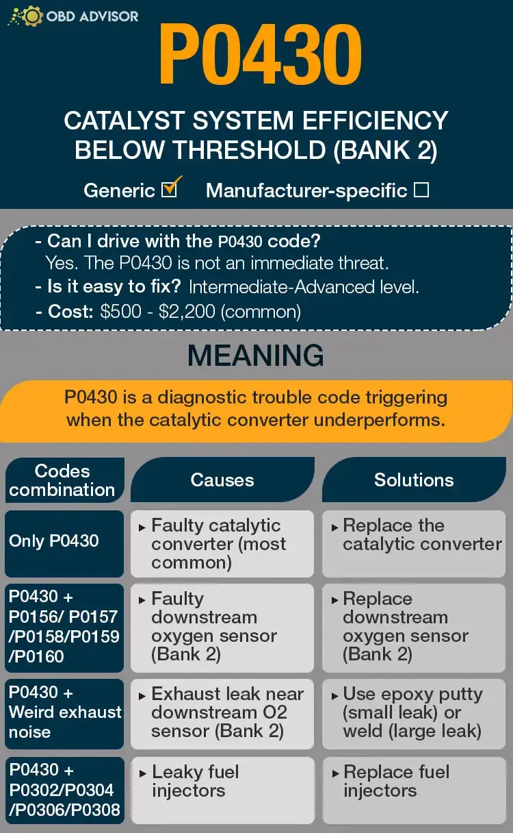
P0430 Causes Identification: Quick View
A problem with your vehicle’s catalytic converter may sometimes trigger more than the P0430 code. An OBD2 scanner may return other DTCs depending on what causes the issue.
The chart below summarizes all possible combinations.
| Codes Combination | Causes | Solutions |
|---|---|---|
| Only P0430 | Faulty catalytic converter (most common) Exhaust leak near downstream O2 sensor (Bank 2) Leaky fuel injectors | Replace the catalytic converter Use epoxy putty (small leak) or weld (large leak) Replace fuel injectors |
| P0430 + P0156/P0157/P0158/P0159/P0160 | Faulty downstream oxygen sensor (Bank 2) | Replace downstream oxygen sensor (Bank 2) |
Note: The causes for each code combination are the most common ones. There can be some uncommon issues hidden under those codes.
P0430: Causes, Symptoms, And How To Fix
Many reasons why your vehicle sets the P0430 code exists. That can vary from model to model, but the following are the most common ones:
Cause #1: Faulty Catalytic Converter
A catalytic converter is designed to last the lifetime of the vehicle. However, it can also become faulty.
In that case, its function will be compromised. This malfunction is detected by the downstream oxygen sensor, which signals PCM to activate the P0430 code.
The most common symptoms of a bad catalytic converter include the following:
- Rotten egg smell
- Rattling noise underneath the car
- Decreased gas mileage
- Engine misfiring
- Failed emission test
- Check engine light on
A faulty catalytic converter requires replacement. You can do this yourself, but this process is a little advanced and expensive. But, of course, bringing it to mechanics is even more pricey.
Cause #2: Faulty Downstream Oxygen Sensor
A downstream oxygen sensor keeps track of the catalytic converter’s performance.
Its failure will trick the PCM into thinking the catalytic converter is bad, triggering the P0430.
If this is your problem, you may receive other DTCs along with P0430, such as P0156, P0157, P0158, P0159, and P0160.
Downstream O2 sensors do not take part in the air-fuel ratio adjustment process. As a result, there is almost no symptom in this case but the CEL.
The most realistic solution is to replace the faulty downstream O2 sensor. Fortunately, it isn’t expensive or difficult to install without the help of a mechanic.
Cause #3: Exhaust Leak Near Downstream O2 sensor
A leaking exhaust near the downstream O2 sensor will let the air go into the pipe. This air confuses the sensor’s reading, which makes the PCM activate the P0430 code as a warning sign.
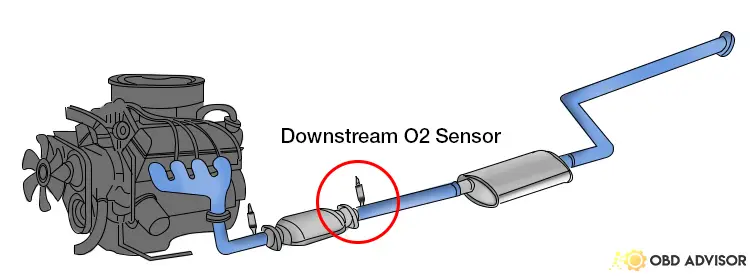
An exhaust leak can cause the following:
- Check engine light on
- Blowing sound from underneath your car
- Louder engine sound than usual
- Low engine performance
- Decreased fuel efficiency
- Unusual odor in the cabin
Use a smoke test to identify the leak.
After confirming the location, you can repair it using the epoxy putty or welding the leak. It can be a difficult task for anyone unfamiliar with DIY jobs.
Cause #4: Leaky Fuel Injectors
Leaky fuel injectors will allow more fuel into the combustion cylinder. That disrupts the usual cycle since not all the gas gets burned. The excess finds its way into the exhaust system, where they burn and produce soot that blocks the catalytic converter.
This can also result in high temperatures that literally melt the catalytic converter inside.
Signs of leaky fuel injectors include the following:
- Fuel consumption increases
- Poor and shaky idling
- Gasoline smell
- Hard starts (when the engine is hot)
- Bad emission performance
The solution to leaking fuel injectors is replacing them. This is not an easy job, so it is recommended to visit a mechanic.
How Much Does It Cost To Fix P0430?
The cost of fixing P0430 varies significantly depending on the affected part, model, and year of the car.
Catalytic converters are the most common culprits, which cost about $500 – $2,200 to fix at an auto repair shop. You can save on the labor fee through a DIY approach. In that case, you will need $400 – $2000.
The Estimated Repair Cost Of P0430
| Solutions | Cost |
|---|---|
| Replace the catalytic converter | DIY: $400 – $2,000 Repair shop: $500 – $2,200 |
| Replace downstream oxygen sensor (Bank 2) | DIY: $20 – $200 Repair shop: $60 – $300 |
| Use epoxy putty (small leak) | DIY: under $10 Repair shop: not recommended |
| Weld the leak (large leak) | DIY: not recommended Repair shop: $30 – $100 |
| Replace fuel injectors | DIY: $400 – $900 Repair shop: $600 – $1,200 |
Note: The data in this table was collected in June 2022. The actual price depends on many factors, such as your car’s make and year, mechanic’s rate, etc.
You Ask, I Answer
The P0430 is a moderate code but requires immediate fixing to avoid more internal damages.
And if you have dealt with the P0430 code before, tell us what the problem was and how you fixed it. Use the comment section below to share your thoughts.
See ya!
Read more: The 9 Best OBD2 Scanners for 2024: The Only Review You Need
U1900 Ford Code: CAN Communication Bus Fault
U1900 Ford Code: CAN Communication Bus Fault
Discover the ins and outs of the U1900 Ford code with our expert guidance.
If you own a Ford vehicle and have encountered this code, understanding its meaning, severity, symptoms, causes, and the necessary steps for diagnosis and repair is crucial.
You’re in good hands! Count on our experience and expertise as we provide you with valuable insights to help you deal with the code.
So, let’s dive in!
U1900 Code on Ford: An Overview
Here’s a brief overview of the U1900 Ford code:
- Definition: CAN Communication Bus Fault (Receive Error)
- Severity: Low
- DIY Skill Level: Intermediate
- Continue To Drive?: Yes
- Estimated Repair Cost: $0-$200
U1900 Ford Code Meaning: What Does It Signify?
The U1900 code on Ford indicates a failure in the communication bus. When the bus fails to receive a specific error or cannot relay that message to the powertrain control module (PCM), it triggers this error code. This can be caused by a communication failure between various components within the system.
In certain cases, this code is commonly found in models such as the Expedition, Explorer, F150, F250, and Focus. The CAN (Controller Area Network) serial communication system connects all the control modules in a Ford vehicle. However, U1900 primarily refers to communication failures within the circuits connecting the PCM, ABS control module, and instrument cluster. If any of these parts fail to transmit their signals to the PCM, the U1900 code may appear.
Note: The Ford U1900 code can occasionally be a “ghost code,” appearing when connecting a scanner to the data link connector with the ignition on or while the engine is running.
U1900 Ford Code Severity: Assessing Its Impact
The severity level of the U1900 fault code is low to medium. Many experienced mechanics and vehicle owners have reported that this code does not pose a significant concern.
In fact, it is often considered a “ghost code” (as noted above) or a result of the diagnostics process itself rather than an actual fault. However, it is worth mentioning that there might be other Ford-specific stored codes that may not be detected by a generic code reader.
(Image credit: Ford Owners Club)
Considering the widespread occurrence of this code and the general consensus among owners, there is no immediate cause for alarm. If your vehicle displays the U1900 code only without any apparent performance or drivability problems, it is generally safe to continue driving. However, it is advisable to monitor the vehicle’s performance and address any other related codes or symptoms that may arise.
U1900 Ford Code Symptoms: What To Look Out For
The U1900 Ford code typically does not cause specific symptoms or drivability issues on its own. However, in worst cases, it may be accompanied by these signs:
- Illumination of the check engine light and other dashboard lights like the ABS light or AWD light
- 4WD system malfunction (common in 4WD-equipped Ford applications)
- Potential no-start condition (especially on F-series trucks)
Read more: Ford Dashboard Symbols and Meaning (FULL list, Free Download)
Exploring U1900 Ford Code Causes
Common causes of the U1900 code include:
- Loose wiring connections
- Communication failure within the CAN system
- Faulty ABS control module
- Malfunctioning instrument cluster (possible racks in joints, connector pins, or pads on the printed circuit board)
- Issues with the trailer brake controller
Read more: Ford OBD2 Codes List for FREE Download
U1900 Ford Code Diagnosis And Repair
If you’re sure that the U1900 code is not a “ghost code” and it is affecting your driving experience, follow these steps to address the issue effectively.
Essential Tools And Parts
- OBD-II scanner
- Multimeter
- Wiring diagram for the vehicle
- Electrical contact cleaner
- Replacement wiring connectors (if necessary)
- Diagnostic manual for the specific vehicle model
Step-by-Step Guide
- Connect the OBD-II scanner and retrieve any stored codes.
- Inspect the wiring connections related to the U1900 code.
- Use a multimeter to check for continuity and proper voltage levels.
- Check for loose or damaged wiring connectors and repair or replace them as needed.
- Inspect the ABS control module, instrument cluster, and trailer brake controller for any visible signs of damage or malfunction.
- Clean the electrical contacts and ensure proper connections.
- Perform a thorough inspection of the CAN bus system and related components.
- If necessary, consult the vehicle’s diagnostic manual for specific troubleshooting steps.
DIY Repair Level And Estimated Costs
The DIY repair level for the U1900 Ford fault code is moderate to advanced. You can try basic troubleshooting and inspections, but seeking professional assistance is advisable for complex electrical systems.
The estimated costs for repairing the U1900 code may vary depending on the specific cause and required repairs. Costs can range from minimal expenses for simple wiring repairs to higher expenses if components like the ABS control module or instrument cluster need replacement.
Here is a rough cost estimate for common repair tasks:
| Repair Task | Cost Range |
| Wiring repairs | $50 – $200 |
| ABS control module replacement | $200 – $600 |
| Instrument cluster replacement | $300 – $800 |
| Trailer brake controller replacement | $100 – $400 |
Please keep in mind that these cost ranges are approximate and can vary depending on various factors, such as the specific vehicle model, location, and labor rates. Consult a qualified mechanic or technician to get an accurate diagnosis and cost estimate for your vehicle.
Wrapping Up
In conclusion, the U1900 Ford fault code is generally not a big problem – if you have insights and knowledge about it.
You can fix the code and get everything back to normal by following the steps we’ve provided. If you’re uncomfortable working with electrical systems, it’s best to ask for help from a professional.
We hope this guide has been helpful to you. If you have any questions, feel free to ask in the comments below!
Reference Sources
- JustAnswer, U1900+dtc.pdf.
- Vehicle History, What does the Ford C-Max fault code U1900 mean?
- ACTRONICS LTD, Ford Focus instrument cluster – U1900 fault.
- TroubleCodes.net, U1900 – CAN Communication Bus Fault.
- FORScan forum, U1900 – CAN communication bus fault
- JustAnswer, Fix U1900 code.
- Ford Owners Club, U1900 code, I’ve tried everything.
P1217 Nissan Code: Engine Cooling Insights
P1217 Nissan Code: Engine Cooling Insights
P1217 Code: A Quick Overview
What Does The P1217 Code Mean On Nissan?
Sometimes, code P1217 is accompanied by other codes: DTC UXXXX and DTC P0607. DTC UXXXX points to communication problems in the vehicle’s networks, affecting various systems like the CAN bus. DTC P0607 indicates an issue with the ECM’s memory or processing, often due to electrical or software problems. Fixing these codes is essential for accurate communication between the ECM and other systems.
Before addressing P1217, it’s vital to tackle DTC UXXXX and DTC P0607. These codes highlight underlying issues that can impact temperature readings and engine performance. Addressing them first ensures proper system functioning and sets the stage for resolving the P1217 code effectively.
How Severe Is The Nissan Code P1217?
The severity of this code is moderate to high. Moreover, operating an overheating engine can lead to significant damage, including warped components and potential engine failure. Therefore, continuing to drive with this code activated is not recommended, as it may result in costly repairs and safety hazards.
If the P1217 code appears, it’s advisable to pull over, turn off the engine, and allow it to cool down. Additionally, prompt attention to this issue can prevent extensive damage and ensure the safety and reliability of your vehicle on the road.
What Are The Symptoms Of The P1217 Codes On Nissan Vehicles?
When encountering Nissan Code P1217, drivers and technicians may observe the following symptoms:
- Engine overheating
- Increased engine temperature gauge readings
- Illuminated check engine light
- Reduced engine performance
- Possible engine misfire or hesitation
Read more: P1564 Nissan Code: How to Get Your Cruise Control Back on Track
What Causes The P1217 Nissan Code?
The triggering of Nissan Code P1217 can be attributed to various factors, including:
- Open or shorted cooling fan circuit
- IPDM E/R problems
- Defective cooling fan motor
- Faulty radiator hose or radiator cap
- Bad radiator
- Water pump or thermostat problems
How To Diagnose And Fix The P1217 Nissan Code
Addressing Nissan Code P1217 involves a systematic diagnosis and repair process. Furthermore, here’s a breakdown of the essential tools and parts, followed by a step-by-step guide for the procedure.
Essential Tools And Parts
- Diagnostic scan tool (preferably with active test capability)
- Coolant pressure tester
- Basic hand tools (wrenches, sockets, pliers, etc.)
- Replacement coolant and engine oil
- Cooling system components (cooling fan, radiator, water pump, thermostat, etc.)
Step-by-Step Procedure
Before processing the diagnostic procedure, please top up your coolant to a specified level with a proper mixed ratio. In addition, you need to perform an oil change.
Step 1: Perform an “ACTIVE TEST” using a diagnostic scan tool to assess cooling fan speed.
Step 2: If needed, activate the IPDM E/R auto-active test to check the cooling fan motor operation.
Step 3: Check the cooling system for hoses, radiators, and water pump leaks. Repair or replace malfunctioning parts as necessary.
Step 4: Examine the radiator cap for any issues. Replace if needed.
Step 5: Inspect and test the thermostat’s functionality. Replace if required.
Step 6: Check the water control valve’s operation. Replace if faulty.
Step 7: Inspect the engine coolant temperature sensor. Replace if not functioning properly.
Step 8: If the root cause can’t be determined, refer to the troubleshooting chart for further analysis.
Note: If you’re not confident in completing these steps, consider seeking assistance from a professional mechanic.
Read more: P1701 Nissan Code: Get It Fixed With Ease Like Never Before
DIY Repair Level And Estimated Costs
The DIY repair level for P1217 diagnosis and repair can vary based on your experience and comfort level with automotive repairs. While some steps like checking coolant levels and inspecting components are relatively straightforward, tasks like replacing the water pump or thermostat might require more advanced skills.
For professional repair assistance, the estimated costs can vary depending on the specific problem and location. Moreover, here’s a rough estimate of potential costs for main repair tasks:
| Repair Task | Estimated Cost Range |
| Coolant Flush and Change | $100 – $200 |
| Oil Change | $35 – $75 |
| Replacing Cooling Fan | $100 – $300 |
| Replacing Radiator | $150 – $400 |
| Replacing Water Pump | $100 – $250 |
| Replacing Thermostat | $50 – $150 |
P1217 Nissan Infographic
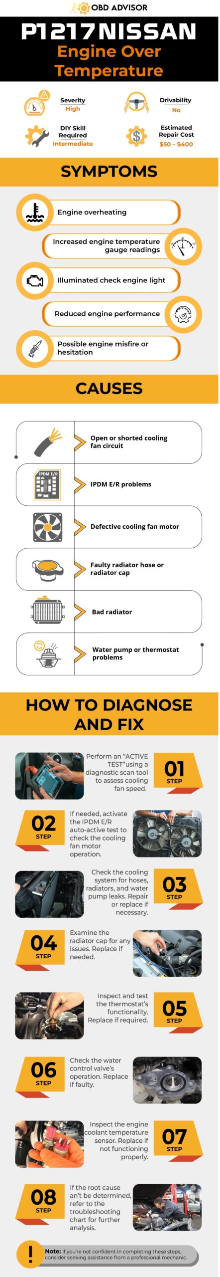
Final Thoughts
Facing the P1217 Nissan Code might seem daunting, but armed with the right knowledge, you’re well-equipped to tackle it head-on. Remember, the cooling system is a critical component that keeps your engine running smoothly, and issues like overheating can lead to costly repairs. Whether you’re a seasoned DIY enthusiast or prefer seeking professional assistance, staying proactive is key.
If this article helped shed light on the P1217 code or if you have any insights to share, we’d love to hear from you.
Feel free to drop a comment below and share this information with fellow car enthusiasts who might benefit. Safe driving, and stay cool under the hood!
Reference Sources
- Nissan Sentra. P1217 Engine Over Temperature.
- Nissan Altima. IPDM E/R (Intelligent Power Distribution Module Engine Room).
P0018 Code: Crankshaft Position – Camshaft Position Correlation (Bank 2 Sensor A)
P0018 Code: Crankshaft Position – Camshaft Position Correlation (Bank 2 Sensor A)
If you’ve encountered the P0018 code during a scan of your vehicle’s onboard diagnostic system, fret not! We’re here to discuss its meaning and implications.
So, what does the code P0018 mean? In simple terms, it points to a potential issue with the correlation between the crankshaft position and the camshaft position on Bank 2 Sensor A. Dive in to learn more about this issue as we’ve got you covered with an in-depth exploration of its causes, symptoms, diagnosis, and repair methods.
P0018 Code: An Overview
Check the key information of the P0018 code below!
- Definition: Crankshaft Position – Camshaft Position Correlation (Bank 2 Sensor A)
- Severity: High
- DIY Skill Level: Intermediate
- Continue To Drive?: No
- Estimated Repair Cost: $50 – $500
What Does The P0018 Code Mean?
P0018 is an OBD-II generic code indicating a lack of correlation between the signals from the camshaft position (CMP) sensor A for bank 2 and the crankshaft position sensor (CKP). This code is commonly triggered in various car brands such as Ford, Subaru, Chevrolet, Hyundai, Kia, GMC, Mercedes, Toyota, Subaru, Jeep, Audi, and Lexus.
In a typical engine, bank 2 typically refers to the side of the engine that doesn’t house cylinder #1. The “A” sensor is commonly found on the intake camshaft side. It’s important to note that the P0018 code is often associated with other CKP sensor-related codes such as P0016, P0017, and P0019.
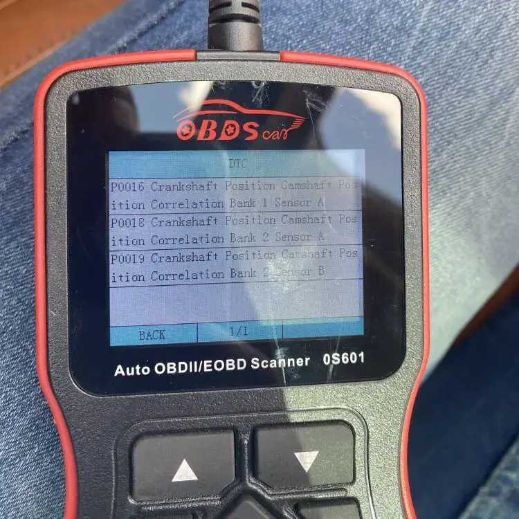
The CMP sensor A for bank 2 is responsible for monitoring the position and rotation speed of the camshaft. In contrast, the CKP sensor detects the position and rotation speed of the crankshaft. The Powertrain Control Module (PCM) relies on these signals to properly synchronize the camshaft and crankshaft.
When the PCM detects that the crankshaft and camshaft signals are out of time by a specific number of degrees, it triggers the P0018 code. This means that the correlation between the signals from the CMP sensor A for bank 2 and the CKP sensor is not within the expected parameters. The specific number of degrees may vary depending on the vehicle and manufacturer.
Special Notes
The systems/components involved in triggering this code can vary depending on the specific car brand and model. For example, in General Motors (GM) vehicles, the issue may be related to the CMP actuator solenoid or the timing chain. In Subaru vehicles, it may be associated with the active valve control system (AVCS) and related DTCs. In Ford vehicles, the code may refer to the Variable Camshaft Timing (VCT) system.
Many car manufacturers have issued Technical Service Bulletins (TSBs) related to the P0018 code, indicating a known issue and providing guidance for diagnosis and repair. For instance, the GM TSB 18-144-453 highlights potential causes and solutions for this code. The Subaru TSB 02-163-16R provides inspection and repair procedures for AVCS-related DTCs, including P0018. The Ford TSB 18-2360 addresses concerns with Bank 2 VCT in specific models.
Reminder: Consult the relevant TSBs specific to your vehicle’s make, model, and year for detailed information on diagnosing and resolving the P0018 code.
How Serious is The P0018 Code?
The severity of the P0018 code is typically considered medium to high, depending on the specific circumstances and the extent of the issue. Generally, this code can potentially affect the engine’s performance and fuel efficiency. It is recommended not to continue driving with the P0018 code unresolved for an extended period.
Driving with this code may result in decreased engine performance, rough idling, reduced fuel economy, and potential damage to engine components over time. Ignoring the issue can lead to more severe engine problems and costly repairs. It is advisable to have the vehicle diagnosed and repaired by a qualified mechanic as soon as possible to prevent further damage and ensure optimal engine performance and reliability.
Symptoms of P0018 Code to Watch Out For
The following are common symptoms associated with the P0018 code:
- Check Engine Light (CEL) illuminated
- Engine misfires or runs rough
- Decreased engine performance
- Rough idling or stalling
- Reduced fuel efficiency
- Engine hesitation or surging
Common Causes of P0018 Code
The P0018 code can be triggered by various factors, including:
- Low engine oil level or improper oil viscosity.
- Wiring problems related to the crankshaft or camshaft sensors.
- Damaged or malfunctioning crankshaft or camshaft sensors.
- Timing chain or belt issues (stretching, misalignment, or wear).
- Issues with timing chain tensioner or guides.
- Faulty camshaft variable timing solenoid or variable valve timing (VVT) actuator.
- Engine timing set incorrectly.
- Problems with the VCT unit, such as alignment or solenoid issues (Ford vehicles).
How To Diagnose and Fix The P0018 Code?
This section will provide you with a step-by-step guide to diagnose and resolve the P0018 code. We will walk you through the process of inspecting timing components, sensors, and wiring and guide you on the necessary repairs or replacements to address the issue effectively. Check it out!
Essential Tools and Parts
- OBD-II scanner or scan tool
- Basic hand tools (such as wrenches, sockets, and pliers)
- CKP/CMP sensor
- Timing chain or belt (if necessary)
- Variable valve timing (VVT) solenoid (if necessary)
- Engine oil and oil filter (if required)
Step-by-step Procedure
Step 1: Retrieve DTCs
Scan for codes using an OBD-II scanner or scan tool. If any CKP or CMP sensor-related DTCs are present, prioritize diagnosing and addressing them first. If there are no CKP or CMP sensor-related DTCs, proceed with the following steps.
Step 2: Check Engine Oil
Check the engine oil level and ensure it meets the manufacturer’s specified range. Adjust or replace the engine oil or the oil filter if necessary.
Step 3: Inspect Sensor Wiring
Inspect the wiring related to the crankshaft and camshaft sensors for any damage, loose connections, or corrosion. Repair or replace as needed.
Step 4: Check Timing Components
- Verify that the engine timing is correctly set according to the manufacturer’s specifications.
- Inspect the timing chain or belt, along with the timing chain tensioner and guides, for stretching, misalignment, wear, and proper operation.
- Also, inspect the camshaft variable timing solenoid or variable valve timing actuator for faults, malfunctions, or wear.
Step 5: Clear Codes and Test Drive
Clear all stored codes and test drive the vehicle to verify if the P0018 code returns.
Note: It is recommended to consult the specific service manual for your vehicle make, model, and year to obtain detailed step-by-step instructions tailored to your car.
DIY Repair Level and Estimated Costs
The diagnosis and repair procedure for the P0018 code can range in complexity from intermediate to advanced. Simple tasks such as inspecting the engine oil pressure may be manageable for DIY enthusiasts. However, replacing components like the CMP sensor, timing chain or belt, or VVT solenoid may require advanced mechanical skills and specialized tools. It is advisable to seek assistance from a qualified mechanic or technician if you are unsure about performing the repairs yourself.
The estimated costs for resolving the P0018 code can vary depending on the vehicle make, model, and location. Costs typically involve the price of replacement parts, labor charges, and any additional repairs needed. Below is a breakdown of estimated repair costs for addressing the P0018 code:
| Repair Task | Cost Estimate |
| Engine Oil Change | $50 – $100 |
| Wiring Repair | $50 – $200 |
| Sensor Replacement | $50 – $200 |
| Timing Components Repair/Replacement | $100 – $500 |
Note: Consult with local repair shops or dealerships to obtain accurate estimates for the specific repairs required in your case.
Wrapping Up
In conclusion, it’s important to understand and address the P0018 code to keep your engine running smoothly. By diagnosing and fixing camshaft timing issues, you can improve fuel efficiency, prevent further damage, and ensure your vehicle performs reliably. If you need assistance, consult the service manual or seek professional help.
Feel free to share this helpful information with others. If you have any comments or questions, let us know. For a comprehensive list of OBD codes, you can utilize our OBD Code List Generator tool. Additionally, our OBD code lookup tool can assist you in searching for specific codes and their meanings.
Stay informed and keep your vehicle running smoothly!
Reference Sources
Wikipedia, Timing Chain.
Austin Community College, Variable Valve Timing (VVT).
P2006 Code: Intake Manifold Runner Control Stuck Closed Bank 1
P2006 Code: Intake Manifold Runner Control Stuck Closed Bank 1
If you’ve encountered the P2006 trouble code on your vehicle, it’s essential to address it promptly to ensure optimal engine performance. The P2006 code specifically relates to the intake manifold runner control circuit and indicates that the intake manifold runner flap for bank 1 is stuck closed. But what does this mean for your vehicle?
In this article, we’ll explain the P2006 code, its potential severity, common symptoms, possible causes, diagnostic procedures, and repair solutions. By understanding the details of this code, you’ll be better equipped to take appropriate action and keep your vehicle running smoothly.
Let’s get started.
P2006 Code: An Overview
Take a look at the essential information about the P2006 code below!
- Definition: Intake Manifold Runner Control Stuck Closed Bank 1
- Severity: Medium
- DIY Skill Level: Advanced
- Continue To Drive?: Yes
- Estimated Repair Cost: $50 – $2000
What Does The P2006 Code Mean?
The P2006 diagnostic trouble code (DTC) indicates a malfunction in the intake manifold runner control (IMRC) system. Though this is a generic code that can happen on all vehicles equipped with OBD-II, it is more commonly triggered in Mercedes, Audi, Ford, Hyundai, Mazda, Volkswagen, Kia, Dodge, and Jeep.
The intake manifold runner control system is designed to optimize the airflow into the engine for improved performance and efficiency. It consists of several components, including the intake manifold, intake manifold runner control valve, actuator motor, and linkage. These components work together to adjust the length of the intake runners, which helps optimize the intake air velocity and maximize engine power and torque across different RPM ranges.
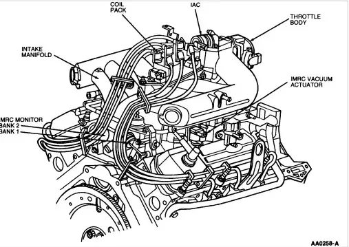
When the P2006 code is triggered, it means that the powertrain control module (PCM) has identified a problem with the IMRC actuator for engine bank 1. Specifically, the actuator is detected to be stuck in the closed position. This issue hinders the proper functioning of the IMRC system, leading to disrupted airflow and negatively impacting the engine’s performance.
The P2006 code shares similarities with other codes related to the IMRC system. They are P2005, P2007, P2008, P2009, P2010 and P2015.
Special Notes
To address this issue, car manufacturers have issued Technical Service Bulletins (TSBs) or recall campaigns. For example, Ford and Mercury have released TSB 06-7-10 related to the P2006 code. Audi has also issued a TSB regarding this code. Additionally, Mazda has a recall campaign specifically addressing the P2006 code in certain models.
These TSBs and recall campaigns provide guidance for diagnosing and repairing the intake manifold runner control system to resolve the P2006 code. It is important for car owners experiencing this issue to consult the specific TSB or recall campaign relevant to their vehicle make and model to ensure proper solutions for your vehicle.
How Serious is the P2006 Code and Should You Continue Driving?
The severity level of the P2006 code is high. While it may not cause immediate drivability issues or safety hazards, it can significantly impact engine performance and fuel efficiency. Ignoring the P2006 code can lead to a reduction in engine power, decreased fuel economy, and potential long-term damage to the engine or emission control system.
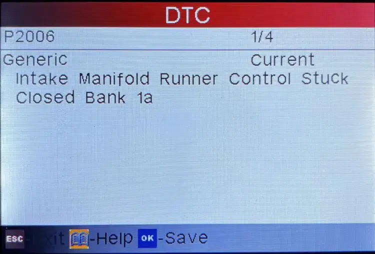
Although you may be able to continue driving for a short period of time with the P2006 code, it is strongly recommended to have the issue diagnosed and repaired as soon as possible. Continuing to drive without resolving the P2006 code can decrease drivability and lead to increased repair costs over time.
Read more: P1077 Honda Code: IMRC/ IMT System Malfunction (Low RPM)
P2006 Code Symptoms and Indicators
When the P2006 code is present, several symptoms may be observed.
- Check Engine Light (MIL) illuminated
- Reduced engine power or hesitation during acceleration
- Decreased fuel efficiency
- Rough idle or stalling
Read more: P026A Code: Causes & Solutions for Charge Air Cooler Issues
Possible Causes of P2006 Code
There are various potential causes for the P2006 code.
- Stuck or malfunctioning IMRC valve
- Faulty actuator motor or linkage
- Vacuum leaks in the intake manifold
- Carbon buildup within the IMRC system, particularly on the IMRC flaps or intake manifold ports
- Open or shorted wiring within the solenoid control circuit for the IMRC actuator
- Broken actuator linkage pin between the actuator and the runner control valve.
- Faulty MAP sensor
- Issues with the Tumble Generator Valve (TGV) in Subaru vehicles (may require TGV delete)
Repairing the P2006 Code: Diagnosis and Solutions
This section will guide you through diagnosing and fixing the P2006 code. Check it out!
Essential Tools and Parts
- OBD-II scanner
- Basic hand tools (such as wrenches, sockets, and screwdrivers)
- Intake manifold gaskets
- Intake manifold runner control valve
- Actuator motor
- Vacuum hoses
Step-by-step Procedure
Step 1: Use an OBD-II scanner to retrieve the P2006 code and any accompanying codes.
Step 2: Inspect the intake manifold, vacuum hoses, and related components for any visible signs of damage, leaks, or loose connections. Repair/replace any damaged components and ensure all connections are secure.
Step 3: Test the intake manifold runner control valve and actuator motor for proper operation and movement. Ensure they are not stuck or malfunctioning. Replace any faulty components.
Step 4: Check the electrical connections and wiring related to the intake manifold runner control system. Look for any open or shorted circuits. Repair/replace any damaged wiring or connectors.
Step 5: Clean or replace the intake manifold and valves to remove carbon buildup.
Step 6: Inspect and test the MAP sensor for proper functionality. Replace the sensor if it is faulty.
Step 7: Clear the codes using the OBD-II scanner and test drive the vehicle to verify if the P2006 code reappears. Monitor the system for any new issues or codes that may arise.
Notes and tips:
- Refer to the vehicle’s service manual or manufacturer’s instructions for specific diagnostic and repair procedures.
- Take precautions when working with the intake manifold to avoid damaging sensitive components.
- Ensure all connections, hoses, and wiring are properly secured and in good condition.
- Consider performing regular maintenance, such as cleaning the intake system, to prevent future carbon buildup.
DIY Repair Level and Estimated Costs
Diagnosing and repairing the P2006 code can range in difficulty, from intermediate to advanced, depending on the specific cause and vehicle model. DIY enthusiasts can perform basic troubleshooting steps, such as checking for visible damage and inspecting connections. However, certain tasks, such as replacing the intake manifold runner control valve or performing a TGV delete in Subaru vehicles, may require advanced mechanical skills and specialized tools.
The estimated costs for the repair tasks associated with addressing the P2006 code will vary depending on the specific vehicle, the extent of the issue, and labor rates. Below is a breakdown of the estimated costs for repairing the P2006 code:
| Repair Task | Estimated Cost |
| Wiring repair | $50 – $200 |
| Intake manifold inspection/repair | $200 – $2000 |
| Vacuum leaks repair | $50 – $100 |
| MAP sensor replacement | $50 – $150 |
Wrapping Up
Picture this: You’re behind the wheel, feeling the power and efficiency of your car as it runs smoothly. By fixing the intake manifold runner control system and handling the P2006 code, you’re improving your vehicles’ performance.
You’ll notice better acceleration and improved gas mileage. We believe that with the information provided above, you’ll be able to repair your car’s problem and reset the P2006 with ease.
If you found this information helpful, please share it with others who might find it useful. Feel free to leave any comments or questions below.
To access a comprehensive list of OBD codes, use our user-friendly OBD Code list generator or our OBD code lookup tool to search for specific codes.
Stay informed and keep your vehicle running smoothly!
Reference Sources
Complete Car, Intake Manifold Runner Control Valve 101.
YourMechanic, Symptoms of a Bad or Failing Intake Manifold Runner Control.
P0151 Code: Understanding O2 Sensor Circuit Low Voltage
P0151 Code: Understanding O2 Sensor Circuit Low Voltage
Welcome, fellow car enthusiasts! Today, we explore a common trouble code in automotive diagnostics that can be puzzling: P0151.
If you’ve ever seen the check engine light illuminate, connected a scanner, and wondered about the meaning behind the P0151 code that has just appeared, you’ve come to the right place for answers. In this article, we’ll provide a comprehensive explanation of the P0151 code, which is defined as the O2 Sensor Circuit Low Voltage (Bank 2, Sensor 1) code. We also cover its causes, severity, potential solutions, and estimated breakdown of repair costs.
So, let’s rev up!
P0151 Code: Quick Overview
Here is an overview of the P0151 code. Take a look!
- Definition: O2 Sensor Circuit Low Voltage (Bank 2, Sensor 1)
- Severity: Medium
- DIY Skill Level: Intermediate
- Continue To Drive?: No
- Estimated Repair Cost: $100 – $300
What Does The P0151 Code Mean?
The P0151 code indicates that the oxygen sensor Bank 2, Sensor 2 detects a voltage lower than the specified range. This sensor is typically located before the catalytic converter on the side of the engine with cylinder bank 2.
The oxygen sensor (O2/H2OS sensor) plays a crucial role in monitoring the oxygen levels in the exhaust gases. It sends voltage signals to the engine control module (ECM), providing feedback on the oxygen content. Based on this information, the ECM adjusts the fuel mixture to achieve optimal combustion and ensures the proper functioning of the emission control system.
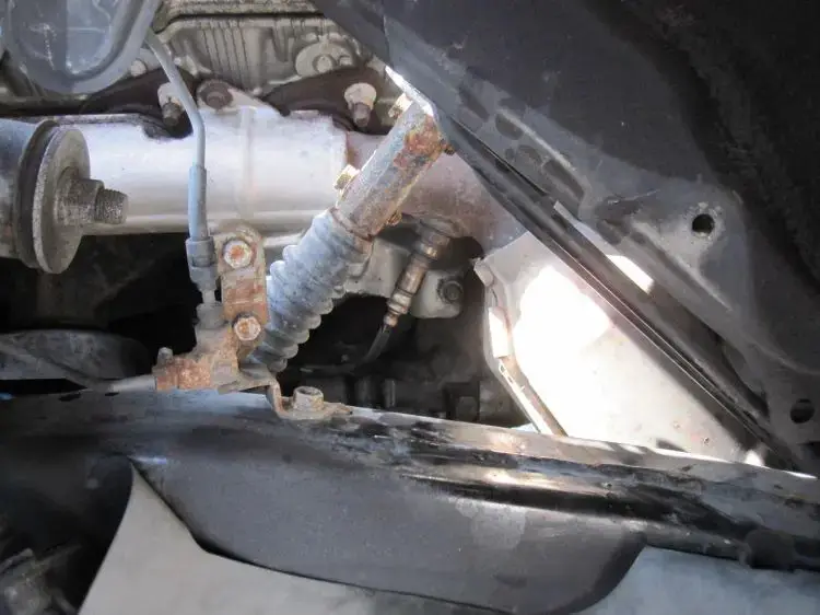
( Image credit: toyota-4runner.org)
It’s important to note that the specific definition of the P0151 code may vary depending on the vehicle manufacturer, although they generally have the same meaning. For instance, in GM vehicles, P0151 is defined as HO2S Circuit Low Voltage Bank 2 Sensor 1, whereas Ford describes this code as O2 Sensor Circuit Low Voltage Bank 2 Sensor 1.
Moreover, while it is commonly found in car brands like Ford (mostly F150) and Chevy, it can also occur in various other makes and models. Other O2 sensor-related codes includes P0136, P0137, and P0131.
Read more: P0136 – O2 Sensor Circuit
Is it Safe to Continue Driving With The Code P0151?
This P0151 code is typically categorized as a moderate-level issue. It can affect the engine’s fuel-air mixture and potentially decrease fuel efficiency and performance.
While the P0151 code may not cause immediate breakdown or safety concerns, it is crucial to address it promptly. Ignoring this code can lead to long-term engine damage and increased emissions. Additionally, prolonged exposure to a faulty air-fuel mixture can negatively impact other engine components, such as the catalytic converter.
Therefore, it is advisable not to continue driving with the P0151 code present. Instead, it is recommended to have the issue diagnosed and repaired as soon as possible. By addressing the root cause and replacing faulty components, you can ensure optimal engine performance, fuel economy, and reduce the risk of further damage.
Signs Of P0151 Trouble Code
In most cases, the main symptom of the P0151 code is the Check Engine Light (CEL) illuminated on the vehicle’s dashboard, typically without any noticeable drivability issues. However, in certain instances, you may encounter additional symptoms, which can include:
- Decreased fuel efficiency
- Poor engine performance
- Rough idling or stalling
- Irregular engine surges or hesitation
- Increased emissions
Read more: P0137: O2 Sensor Circuit Low Voltage (Bank 1 Sensor 2)
What Triggers the P0151 Code on Your Vehicle?
Several potential causes can trigger the P0151 code to appear:
- Faulty oxygen sensor (Bank 2, Sensor 1)
- Wiring issues, such as frayed or damaged wires
- Loose or corroded sensor connections
- Vacuum leaks in the intake manifold or exhaust system
How To Diagnose and Fix This Code
Now that we have a good understanding of the P0151 code, let’s dive into the diagnosis and repair process. In this section, we’ll cover the essential tools and parts needed, provide a step-by-step procedure, and discuss the level of DIY repair along with estimated costs.
Essential Tools and Parts
- OBD-II scanner
- Multimeter
- Oxygen sensor socket or wrench
- Wire connectors
- Electrical tape
- Replacement oxygen sensor (Bank 2, Sensor 1)
- Wiring harness (if necessary)
Step-by-Step Procedure
- Use a compatible OBD-II scanner or diagnostic tool to retrieve the trouble codes from the vehicle’s onboard computer.
- Perform a thorough visual inspection of the O2 sensor and its wiring for any signs of damage, loose connections, or corrosion. Clean/repair if necessary.
- Use a multimeter to measure the voltage output of the O2 sensor and compare it to the manufacturer’s specifications. Repair if the sensor is malfunctioning.
- Inspect the exhaust system for any leaks, blockages, or damage that could affect the O2 sensor’s readings. Repair or replace any faulty components as needed.
- After performing the necessary repairs and inspections, clear codes using the OBD-II scanner and test drive.
Note: It’s recommended to consult the specific repair manual for your vehicle model for detailed instructions tailored to your car’s configuration.
DIY Repair Level and Estimated Costs
The DIY repair level for diagnosing and replacing the oxygen sensor associated with the P0151 code is moderate. While it can be done by experienced DIYers, if you’re unsure or uncomfortable with the process, it’s best to seek the assistance of a professional mechanic.
Below is a repair estimate costs table related to resolving the P0151 code:
| Repair Task | Estimated Cost Range |
| Replacement Oxygen Sensor | $100 – $300 |
| Wiring Repair | $50 – $100 |
Please note that these estimated costs are general ranges and can vary depending on the vehicle make and model, location, and the specific parts required. It’s always recommended to consult with a trusted mechanic or service center to get accurate cost estimates tailored to your specific situation.
Read more: P0131 – O2 Sensor Circuit Low Voltage
Final Thoughts
You’ve now gained valuable insights into the P0151 code and its implications. With this knowledge, you can confidently diagnose and address the O2 Sensor Circuit Low Voltage (Bank 2, Sensor 1) issue. Remember, timely action is key to maintaining optimal engine performance and reducing potential long-term damage.
If you found this article helpful, don’t keep it to yourself! Share it with other car enthusiasts who may be facing similar challenges. We’d love to hear about your experiences or any additional tips and tricks you’ve discovered along the way. Feel free to leave a comment below.
Additionally, don’t forget to take a look at our OBD Code List Generator to find specific code lists, or use our OBD code lookup tool for instant reference.
Safe travels, and keep your cars running smoothly!
Reference:
- ProDemand, P0151, Replaced Oxygen Sensor (B2-S1).
- Chilton Library, DTC P0151.
- Wikipedia, Exhaust system.
P0335 – Crankshaft Position Sensor “A” Circuit
P0335 Code Definition
What Does P0335 Mean?
What Are The Symptoms Of The P0335 Code?
What Are The Causes Of P0335?
How Serious Is The P0335 Code?
How To Diagnose The P0335 Code
Tools You’ll Need:
Method:
Common Mistakes To Avoid While Diagnosing The P0335 Code
What Should You Do To Fix The Code P0335?
Tips To Avoid P0335 In The Future
P20B9 Code: Understanding Reductant Heater Issues & Solutions
P20B9 Code: Understanding Reductant Heater Issues & Solutions
Suddenly encountering the dreaded P20B9 code? No worries. We’re here to help!
The P20B9 code specifically refers to the Reductant Heater ‘A’ Control Circuit/Open. But what does that really mean for your vehicle?
In this article, we’ll provide a clear explanation of the P20B9 code, its severity, common symptoms, possible causes, and the necessary steps for diagnosis and repair.
Let’s get started.
Overview Of The P20B9 Code
To summarize, these are the main highlights of the P20B9 code.
- Definition: Reductant Heater ‘A’ Control Circuit/Open
- Severity: High
- DIY Skill Level: Intermediate
- Continue To Drive?: Yes (Warmer seasons only)
- Estimated Repair Cost: $50 – $500
What Does The P20B9 Code Mean?
The P20B9 code is a diagnostic trouble code (DTC) that indicates an issue with the reductant heater in your vehicle. A stored code P20B9 signifies that the powertrain control module (PCM) has detected the absence of voltage in the control circuit specific to the onboard reductant heater identified as heater “A.”
This code is commonly triggered in vehicles equipped with certain diesel engines, such as Ford Powerstroke (especially the 6.7 Powerstroke), Ram 2500 with Cummins engines, and cars that utilize Duramax engines.

(Image credit: Powerstroke.org)
In modern diesel vehicles, a reductant system reduces harmful emissions, particularly nitrogen oxides (NOx). This system utilizes a specific reductant known as diesel exhaust fluid (DEF) or AdBlue, which consists of a blend of urea and deionized water. The DEF is stored in a dedicated reservoir and introduced into the exhaust flow, where it undergoes a chemical reaction known as Selective Catalytic Reduction (SCR). This process converts NOx into nitrogen and water vapor, thus reducing emissions.
Within the reductant system, the heater plays a crucial role. It is responsible for heating the DEF to optimize its performance, especially during colder temperatures. The reductant heater ‘A’ refers to a specific heater element or circuit related to the DEF system. The control circuit ensures the proper functioning and regulation of the reductant heater. When the control circuit or the heater itself malfunctions or fails to operate within specified parameters, it triggers the P20B9 code.
How Serious Is The P20B9 Code?
While the P20B9 code may not cause immediate drivability problems, it should be considered a high-severity issue. You should address the P20B9 code as soon as possible, especially before the onset of colder weather.
During warmer seasons, the vehicle can still be driven without immediate consequences. However, it is essential to note that the DEF can freeze in colder temperatures if the reductant heater is not functioning properly. This can lead to severe damage to the DEF tank and related components.
Therefore, to avoid costly repairs and potential drivability issues, it is recommended to have the P20B9 code diagnosed and repaired promptly, particularly before the winter months. By addressing the problem promptly, you can ensure the proper operation of the reductant heater system and maintain optimal emissions control.
Read more: P2002: Diesel particulate filter efficiency below threshold
Potential Symptoms Of The P20B9 Code
The P20B9 code may be accompanied by the following symptoms:
- Check Engine Light (CEL) or Malfunction Indicator Lamp (MIL) illuminated on the dashboard
- Reduced engine performance or power
- Increased fuel consumption
- Abnormal black smoke emitted from the vehicle’s exhaust
Common Triggers Of The P20B9 Code
The P20B9 code can be triggered by various factors, including:
- Open or short circuit in the reductant heater ‘A’ control circuit
- Faulty or damaged reductant heater
- Bad reductant temperature sensor
- Malfunctioning SRC controller/PCM or programming error
Read more: P2459 Code: Understanding, DIY Solutions, And Repair Costs
Step-by-Step Guide To Diagnosing & Fixing the P20B9 Code
Don’t let the P20B9 code leave you puzzled – follow our detailed guide, complete with step-by-step instructions, to diagnose and repair any issues affecting your vehicle’s reductant heater system.
Essential Tools And Parts
- OBD-II scanner or code reader
- Multimeter
- Basic hand tools (screwdrivers, wrenches, etc.)
- DEF heater element (if necessary)
- Wiring repair kit (if necessary)
Step-by-step Procedure
Step 1: Use an OBD-II scanner to retrieve the P20B9 code and any additional codes present.
Step 2: Inspect the reductant heater control circuit and wiring for any visible signs of damage or loose connections. If any issues are found, address them by repairing or replacing damaged wiring and ensuring all connections are secure.
Step 3: Test the reductant heater element for continuity using a multimeter. If it is faulty, replace it with a new one.
Step 4: Check the reductant temperature sensor for proper functionality. If the sensor is determined to be faulty, replace it with a new sensor.
Step 5: Verify the operation and communication of the reductant heater control module. Ensure that it is functioning correctly and communicating with the SRC controller/PCM. If any issues are detected, address them accordingly, which may involve repairing or reprogramming the control module.
Step 6: Clear the codes from the vehicle’s memory using the OBD-II scanner and test-drive the car to ensure the P20B9 code does not return.
Note: It is important to consult the vehicle’s service manual for specific instructions and specifications tailored to your particular make and model.
DIY Repair Level And Estimated Costs
The diagnosis and repair of the P20B9 code can range from moderate to advanced DIY repair skills, depending on the specific cause and complexity of the issue. Therefore, it is recommended to have a good understanding of automotive electrical systems and access to the necessary tools.
The estimated costs for repairing the P20B9 code can vary depending on factors such as the cause of the issue, the need for replacement parts, and whether the repair is performed by a professional mechanic or as a DIY project.
Here is a general breakdown of potential costs:
| Repair Task | Estimated Cost |
| Diagnostic fee | $50 – $100 |
| Wiring repair | $50 – $200 |
| Reductant heater replacement | $200 – $500 |
| Reductant temperature sensor replacement | $100 – $200 |
| Control module repair/reprogramming | $200-$500 |
Final Thoughts
Dealing with the P20B9 code is a common challenge among diesel vehicle owners. Therefore, it is crucial to understand how to effectively address this issue.
After reading this article, I hope you are now equipped with the knowledge to diagnose and resolve the problem confidently. Remember to use the appropriate tools and follow the step-by-step procedure outlined earlier.
If you have encountered the P20B9 code or any other OBD-II code, we encourage you to share your experiences and insights in the comments section below.
Stay knowledgeable and empowered in maintaining the performance and efficiency of your vehicle!
Reference Sources
- Wikipedia, Diesel exhaust fluid.
- CNET, What is diesel exhaust fluid and why is it more important than ever?.
P0452 – Evaporative emission system pressure sensor/switch low
P0452 – Evaporative emission system pressure sensor/switch low
The P0452 OBD2 code is one of the milder diagnostic trouble codes you’ll come across. In about 75% of cases, the fix is as simple as tightening your gas cap. Even when the underlying issue is more serious, it won’t affect your engine performance.
The main negative side-effect you’ll see from P0452 is a rise in harmful emissions. Considering it’s often an easy code to clear, that’s reason enough to make the necessary repairs.
P0452 code definition
P0452 (generic): Evaporative emission system pressure sensor/switch low
What does P0452 mean?
Your vehicle evaporative emission control (EVAP) system limits the fuel vapors that escape into the atmosphere in your exhaust. The system’s main component is the charcoal canister, which purges the fuel vapors, trapping harmful particles.
The engine computer monitors the pressure in the EVAP system. Generally, the system’s pressure rises as the temperature goes up and lowers when the stored vapors in the charcoal canister are purged. Depending on the manufacturer, this is tracked either by the fuel tank pressure sensor or a designated EVAP pressure sensor.
When the engine control module (ECM) or powertrain control module (PCM) detects the voltage from this sensor is below standard parameters, the P0452 OBD2 code is triggered. Usually, the code will only trigger after this low voltage has been recorded for a designated length of time, though this varies from one manufacturer to the next.
The EVAP pressure sensor may be located inside the fuel purge line or at the top of the fuel tank. Check your vehicle manual to find out where the sensor is in your engine.
The EVAP system and fuel system are closely linked. Improper pressure in the fuel tank can cause the P0452 code to activate, especially if you also see trouble codes related to the fuel pressure. Vacuum leaks and faulty wiring can also be responsible for P0452.
Many vehicles have an extended warranty on EVAP system components, up to 100,000 miles for some manufacturers. If it seems you’ll need to replace components to clear the P0452 code, check your warranty before buying any parts, as they’ll likely be covered.
What are the symptoms of the P0452 code?
In many cases, you won’t notice any drivability symptoms when the P0452 trouble code is active. The most common symptoms include:
- Activation of the check engine light
- The smell of fuel in the exhaust
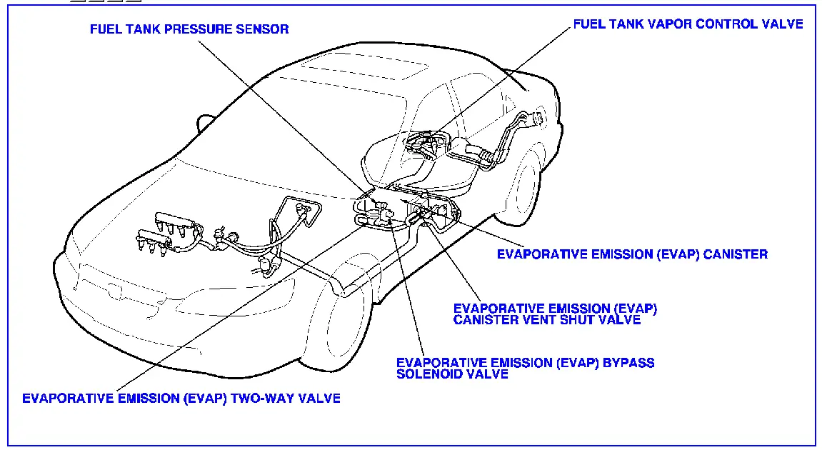
What are the causes of P0452?
- Faulty EVAP pressure sensor or fuel tank pressure sensor
- Faulty or loose wires around sensors
- Opens or shorts in EVAP system wires or wiring harness
- Faulty electrical connections
- The gas cap is loose, leaking, or missing
- Vacuum leaks in the EVAP system
- Plugged or pinched lines in the fuel system
- The charcoal canister is clogged or damaged
How serious is the P0452 code?
On its own, the P0452 diagnostic code is of low severity. You won’t notice any change in the vehicle’s operation, and the risk of further damage to the engine is low. While you will want to make repairs before your next emissions test, you can safely drive for a short time with this code active.
How to diagnose and fix the P0452 code
Tools you’ll need:
- Check for any technical service bulletins related to the P0452 code for your vehicle. Follow the suggested repairs for your make and model before proceeding with the general diagnosis below.
- Read all codes using an OBD2 scan tool. Address any other codes that come up first, especially if you read other EVAP system codes (P0450-P0459). Clear the codes and test drive your vehicle, then rescan to see if you’ve addressed the problem.
- Check your gas cap. If it’s loose, tighten it, and clear codes/rescan. If P0452 comes back, remove the gas cap and inspect it for cracks or wear. Pay close attention to the threads, and clean away any debris or dust that may be impeding a complete seal. Even if you don’t see any damage, you may want to replace the gas cap. It’s a very cheap component to replace and is often the root of P0452 problems.
- Read the freeze frame data using an OBD2 scanner. Check the fuel tank pressure data to verify the computer is reading a vacuum. If it’s not, this indicates either a wiring issue, a vacuum leak, or a faulty sensor.
- Visually inspect the wiring around the EVAP sensor and fuel tank pressure sensor. Replace any wires that are frayed or damaged and inspect the connections for build-up or corrosion. If you found any loose or faulty wires, clear the codes and rescan.
- Use a smoke machine to test your EVAP system for leaks. You can do this by pinching off the vent tube flowing to the EVAP vent control valve, then pressurizing the EVAP system and connecting it to a smoke tester. If there are any leaks, the smoke will give you a visible indication. Replace any leaking hoses or gaskets you discover.
- If there were no leaks, or if these repairs don’t clear the code, the issue is most likely with the sensor itself. Use a multimeter to check the voltage of the EVAP pressure sensor and fuel tank pressure sensor. Compare the readings to the specifications in your vehicle repair manual. Take another set of readings while you apply pressure with the smoke tester. If the readings don’t align with specifications, replace the sensor.
Common mistakes to avoid while diagnosing the P0452 code
Check the obvious and cheap fixes before you start replacing components. The repair could be as simple as tightening the gas cap or reconnecting a loose wire.
Tips to avoid P0452 in the future
The majority of P0452 codes trigger when the driver doesn’t fully close the gas cap after filling up the tank. Taking a second to double-check that the gas cap is screwed on tightly ensures your fuel system can create a proper vacuum, preventing the activation of many EVAP codes.
Read more: P0122 Code: Meaning, Symptoms, Causes, Diagnostics, and Fixes
BMW Fault Codes: FREE Comprehensive OBD1 And OBD2 Codes List
BMW Fault Codes: FREE Comprehensive OBD1 And OBD2 Codes List
Are you a proud BMW owner or a DIY mechanic searching for solutions to those nagging issues in your beloved vehicle?
Look no further!
In this post, we’ll equip you with the knowledge and insights to troubleshoot those pesky problems. Whether you’re dealing with the older OBD1 system or the more advanced OBD2 technology, our comprehensive BMW fault codes list has got your back.
Get ready to unlock the secrets behind those mysterious codes!
BMW OBD1 Codes List and Definition [Free Download]
Free download: Full BMW OBD1 Trouble Codes List and Meaning PDF
Note: Quickly find the specific code you’re looking for using the search box in the table below.
| Code | Definition |
|---|---|
| Code 1211 | MCU (Computer) Malfunction |
| Code 1215 | Air Mass Flow Sensor Fault (MAF) |
| Code 1221 | Oxygen Sensor (O2) |
| Code 1222 | Oxygen Sensor Control |
| Code 1223 | Engine Coolant Temperature (ECT) |
| Code 1224 | Air Intake Temperature |
| Code 1231 | Battery Voltage |
| Code 1232 | Idle Throttle Valve Switch |
| Code 1233 | Full Load Throttle Valve Switch |
| Code 1251 | 1252 Injection Valve |
| Code 1261 | Fuel Pump Relay Circuit |
| Code 1262 | Idle Speed Control Valve |
| Code 1263 | Fuel Tank Vent Valve |
| Code 1264 | Oxygen Sensor Heater Relay |
| Code 1444 | No Failure |
BMW OBD2 Codes List and Definition [FULL]
Free download: Full BMW OBD2 Trouble Codes List and Meaning PDF
Our user-friendly code list is divided into four parts: Powertrain, Network, Body, and Chassis. Easily navigate and find the codes you need for engine, network, body control, and chassis issues.
Note: Use the search box in the table below to quickly find the specific code you’re looking for.
Powertrain (P) Codes List
| Code | Definition |
|---|---|
| P0001 | Fuel Volume Regulator Control Circuit/Open |
| P0002 | Fuel Volume Regulator Control Circuit Range/Performance |
| P0003 | Fuel Volume Regulator Control Circuit Low |
| P0004 | Fuel Volume Regulator Control Circuit High |
| P0005 | Fuel Shutoff Valve “A” Control Circuit/Open |
| P0006 | Fuel Shutoff Valve “A” Control Circuit Low |
| P0007 | Fuel Shutoff Valve “A” Control Circuit High |
| P0008 | Engine Position System Performance |
| P0009 | Engine Position System Performance |
| P0010 | “A” Camshaft Position Actuator Circuit |
| P0011 | “A” Camshaft Position – Timing Over-Advanced or System Performance |
| P0012 | “A” Camshaft Position – Timing Over-Retarded |
| P0013 | “B” Camshaft Position – Actuator Circuit |
| P0014 | “B” Camshaft Position – Timing Over-Advanced or System Performance |
| P0015 | “B” Camshaft Position – Timing Over-Retarded |
| P0016 | Crankshaft Position – Camshaft Position Correlation |
| P0017 | Crankshaft Position – Camshaft Position Correlation |
| P0018 | Crankshaft Position – Camshaft Position Correlation |
| P0019 | Crankshaft Position – Camshaft Position Correlation |
| P0020 | “A” Camshaft Position Actuator Circuit |
| P0021 | “A” Camshaft Position – Timing Over-Advanced or System Performance |
| P0022 | “A” Camshaft Position – Timing Over-Retarded |
| P0023 | “B” Camshaft Position – Actuator Circuit |
| P0024 | “B” Camshaft Position – Timing Over-Advanced or System Performance |
| P0025 | “B” Camshaft Position – Timing Over-Retarded |
| P0026 | Intake Valve Control Solenoid Circuit Range/Performance |
| P0027 | Exhaust Valve Control Solenoid Circuit Range/Performance |
| P0028 | Intake Valve Control Solenoid Circuit Range/Performance |
| P0029 | Exhaust Valve Control Solenoid Circuit Range/Performance |
| P0030 | HO2S Heater Control Circuit |
| P0031 | HO2S Heater Control Circuit Low |
| P0032 | HO2S Heater Control Circuit High |
| P0033 | Turbo Charger Bypass Valve Control Circuit |
| P0034 | Turbo Charger Bypass Valve Control Circuit Low |
| P0035 | Turbo Charger Bypass Valve Control Circuit High |
| P0036 | HO2S Heater Control Circuit |
| P0037 | HO2S Heater Control Circuit Low |
| P0038 | HO2S Heater Control Circuit High |
| P0039 | Turbo/Super Charger Bypass Valve Control Circuit Range/Performance |
| P0040 | O2 Sensor Signals Swapped Bank 1 Sensor 1/ Bank 2 Sensor 1 |
| P0041 | O2 Sensor Signals Swapped Bank 1 Sensor 2/ Bank 2 Sensor 2 |
| P0042 | HO2S Heater Control Circuit |
| P0043 | HO2S Heater Control Circuit Low |
| P0044 | HO2S Heater Control Circuit High |
| P0045 | Turbo/Super Charger Boost Control Solenoid Circuit/Open |
| P0046 | Turbo/Super Charger Boost Control Solenoid Circuit Range/Performance |
| P0047 | Turbo/Super Charger Boost Control Solenoid Circuit Low |
| P0048 | Turbo/Super Charger Boost Control Solenoid Circuit High |
| P0049 | Turbo/Super Charger Turbine Overspeed |
| P0050 | HO2S Heater Control Circuit |
| P0051 | HO2S Heater Control Circuit Low |
| P0052 | HO2S Heater Control Circuit High |
| P0053 | HO2S Heater Resistance |
| P0054 | HO2S Heater Resistance |
| P0055 | HO2S Heater Resistance |
| P0056 | HO2S Heater Control Circuit |
| P0057 | HO2S Heater Control Circuit Low |
| P0058 | HO2S Heater Control Circuit High |
| P0059 | HO2S Heater Resistance |
| P0060 | HO2S Heater Resistance |
| P0061 | HO2S Heater Resistance |
| P0062 | HO2S Heater Control Circuit |
| P0063 | HO2S Heater Control Circuit Low |
| P0064 | HO2S Heater Control Circuit High |
| P0065 | Air Assisted Injector Control Range/Performance |
| P0066 | Air Assisted Injector Control Circuit or Circuit Low |
| P0067 | Air Assisted Injector Control Circuit High |
| P0068 | MAP/MAF – Throttle Position Correlation |
| P0069 | Manifold Absolute Pressure – Barometric Pressure Correlation |
| P0070 | Ambient Air Temperature Sensor Circuit |
| P0071 | Ambient Air Temperature Sensor Range/Performance |
| P0072 | Ambient Air Temperature Sensor Circuit Low |
| P0073 | Ambient Air Temperature Sensor Circuit High |
| P0074 | Ambient Air Temperature Sensor Circuit Intermittent |
| P0075 | Intake Valve Control Solenoid Circuit |
| P0076 | Intake Valve Control Solenoid Circuit Low |
| P0077 | Intake Valve Control Solenoid Circuit High |
| P0078 | Exhaust Valve Control Solenoid Circuit |
| P0079 | Exhaust Valve Control Solenoid Circuit Low |
| P0080 | Exhaust Valve Control Solenoid Circuit High |
| P0081 | Intake Valve Control Solenoid Circuit |
| P0082 | Intake Valve Control Solenoid Circuit Low |
| P0083 | Intake Valve Control Solenoid Circuit High |
| P0084 | Exhaust Valve Control Solenoid Circuit |
| P0085 | Exhaust Valve Control Solenoid Circuit Low |
| P0086 | Exhaust Valve Control Solenoid Circuit High |
| P0087 | Fuel Rail/System Pressure – Too Low |
| P0088 | Fuel Rail/System Pressure – Too High |
| P0089 | Fuel Pressure Regulator 1 Performance |
| P0090 | Fuel Pressure Regulator 1 Control Circuit |
| P0091 | Fuel Pressure Regulator 1 Control Circuit Low |
| P0092 | Fuel Pressure Regulator 1 Control Circuit High |
| P0093 | Fuel System Leak Detected – Large Leak |
| P0094 | Fuel System Leak Detected – Small Leak |
| P0095 | Intake Air Temperature Sensor 2 Circuit |
| P0096 | Intake Air Temperature Sensor 2 Circuit Range/Performance |
| P0097 | Intake Air Temperature Sensor 2 Circuit Low |
| P0098 | Intake Air Temperature Sensor 2 Circuit High |
| P0099 | Intake Air Temperature Sensor 2 Circuit Intermittent/Erratic |
| P0100 | Mass or Volume Air Flow Circuit |
| P0101 | Mass or Volume Air Flow Circuit Range/Performance |
| P0102 | Mass or Volume Air Flow Circuit Low Input |
| P0103 | Mass or Volume Air Flow Circuit High Input |
| P0104 | Mass or Volume Air Flow Circuit Intermittent |
| P0105 | Manifold Absolute Pressure/Barometric Pressure Circuit |
| P0106 | Manifold Absolute Pressure/Barometric Pressure Circuit Range/Performance |
| P0107 | Manifold Absolute Pressure/Barometric Pressure Circuit Low Input |
| P0108 | Manifold Absolute Pressure/Barometric Pressure Circuit High Input |
| P0109 | Manifold Absolute Pressure/Barometric Pressure Circuit Intermittent |
| P0110 | Intake Air Temperature Sensor 1 Circuit |
| P0111 | Intake Air Temperature Sensor 1 Circuit Range/Performance |
| P0112 | Intake Air Temperature Sensor 1 Circuit Low |
| P0113 | Intake Air Temperature Sensor 1 Circuit High |
| P0114 | Intake Air Temperature Sensor 1 Circuit Intermittent |
| P0115 | Engine Coolant Temperature Circuit |
| P0116 | Engine Coolant Temperature Circuit Range/Performance |
| P0117 | Engine Coolant Temperature Circuit Low |
| P0118 | Engine Coolant Temperature Circuit High |
| P0119 | Engine Coolant Temperature Circuit Intermittent |
| P0120 | Throttle/Pedal Position Sensor/Switch “A” Circuit |
| P0121 | Throttle/Pedal Position Sensor/Switch “A” Circuit Range/Performance |
| P0122 | Throttle/Pedal Position Sensor/Switch “A” Circuit Low |
| P0123 | Throttle/Pedal Position Sensor/Switch “A” Circuit High |
| P0124 | Throttle/Pedal Position Sensor/Switch “A” Circuit Intermittent |
| P0125 | Insufficient Coolant Temperature for Closed Loop Fuel Control |
| P0126 | Insufficient Coolant Temperature for Stable Operation |
| P0127 | Intake Air Temperature Too High |
| P0128 | Coolant Thermostat (Coolant Temperature Below Thermostat Regulating Temperature) |
| P0129 | Barometric Pressure Too Low |
| P0130 | O2 Sensor Circuit |
| P0131 | O2 Sensor Circuit Low Voltage |
| P0132 | O2 Sensor Circuit High Voltage |
| P0133 | O2 Sensor Circuit Slow Response |
| P0134 | O2 Sensor Circuit No Activity Detected |
| P0135 | O2 Sensor Heater Circuit |
| P0136 | O2 Sensor Circuit |
| P0137 | O2 Sensor Circuit Low Voltage |
| P0138 | O2 Sensor Circuit High Voltage |
| P0139 | O2 Sensor Circuit Slow Response |
| P0140 | O2 Sensor Circuit No Activity Detected |
| P0141 | O2 Sensor Heater Circuit |
| P0142 | O2 Sensor Circuit |
| P0143 | O2 Sensor Circuit Low Voltage |
| P0144 | O2 Sensor Circuit High Voltage |
| P0145 | O2 Sensor Circuit Slow Response |
| P0146 | O2 Sensor Circuit No Activity Detected |
| P0147 | O2 Sensor Heater Circuit |
| P0148 | Fuel Delivery Error |
| P0149 | Fuel Timing Error |
| P0150 | O2 Sensor Circuit |
| P0151 | O2 Sensor Circuit Low Voltage |
| P0152 | O2 Sensor Circuit High Voltage |
| P0153 | O2 Sensor Circuit Slow Response |
| P0154 | O2 Sensor Circuit No Activity Detected |
| P0155 | O2 Sensor Heater Circuit |
| P0156 | O2 Sensor Circuit |
| P0157 | O2 Sensor Circuit Low Voltage |
| P0158 | O2 Sensor Circuit High Voltage |
| P0159 | O2 Sensor Circuit Slow Response |
| P0160 | O2 Sensor Circuit No Activity Detected |
| P0161 | O2 Sensor Heater Circuit |
| P0162 | O2 Sensor Circuit |
| P0163 | O2 Sensor Circuit Low Voltage |
| P0164 | O2 Sensor Circuit High Voltage |
| P0165 | O2 Sensor Circuit Slow Response |
| P0166 | O2 Sensor Circuit No Activity Detected |
| P0167 | O2 Sensor Heater Circuit |
| P0168 | Fuel Temperature Too High |
| P0169 | Incorrect Fuel Composition |
| P0170 | Fuel Trim |
| P0171 | System Too Lean |
| P0172 | System Too Rich |
| P0173 | Fuel Trim |
| P0174 | System Too Lean |
| P0175 | System Too Rich |
| P0176 | Fuel Composition Sensor Circuit |
| P0177 | Fuel Composition Sensor Circuit Range/Performance |
| P0178 | Fuel Composition Sensor Circuit Low |
| P0179 | Fuel Composition Sensor Circuit High |
| P0180 | Fuel Temperature Sensor A Circuit |
| P0181 | Fuel Temperature Sensor A Circuit Range/Performance |
| P0182 | Fuel Temperature Sensor A Circuit Low |
| P0183 | Fuel Temperature Sensor A Circuit High |
| P0184 | Fuel Temperature Sensor A Circuit Intermittent |
| P0185 | Fuel Temperature Sensor B Circuit |
| P0186 | Fuel Temperature Sensor B Circuit Range/Performance |
| P0187 | Fuel Temperature Sensor B Circuit Low |
| P0188 | Fuel Temperature Sensor B Circuit High |
| P0189 | Fuel Temperature Sensor B Circuit Intermittent |
| P0190 | Fuel Rail Pressure Sensor Circuit |
| P0191 | Fuel Rail Pressure Sensor Circuit Range/Performance |
| P0192 | Fuel Rail Pressure Sensor Circuit Low |
| P0193 | Fuel Rail Pressure Sensor Circuit High |
| P0194 | Fuel Rail Pressure Sensor Circuit Intermittent |
| P0195 | Engine Oil Temperature Sensor |
| P0196 | Engine Oil Temperature Sensor Range/Performance |
| P0197 | Engine Oil Temperature Sensor Low |
| P0198 | Engine Oil Temperature Sensor High |
| P0199 | Engine Oil Temperature Sensor Intermittent |
| P0200 | Injector Circuit/Open |
| P0201 | Injector Circuit/Open – Cylinder 1 |
| P0202 | Injector Circuit/Open – Cylinder 2 |
| P0203 | Injector Circuit/Open – Cylinder 3 |
| P0204 | Injector Circuit/Open – Cylinder 4 |
| P0205 | Injector Circuit/Open – Cylinder 5 |
| P0206 | Injector Circuit/Open – Cylinder 6 |
| P0207 | Injector Circuit/Open – Cylinder 7 |
| P0208 | Injector Circuit/Open – Cylinder 8 |
| P0209 | Injector Circuit/Open – Cylinder 9 |
| P0210 | Injector Circuit/Open – Cylinder 10 |
| P0211 | Injector Circuit/Open – Cylinder 11 |
| P0212 | Injector Circuit/Open – Cylinder 12 |
| P0213 | Cold Start Injector 1 |
| P0214 | Cold Start Injector 2 |
| P0215 | Engine Shutoff Solenoid |
| P0216 | Injector/Injection Timing Control Circuit |
| P0217 | Engine Coolant Over Temperature Condition |
| P0218 | Transmission Fluid Over Temperature Condition |
| P0219 | Engine Overspeed Condition |
| P0220 | Throttle/Pedal Position Sensor/Switch “B” Circuit |
| P0221 | Throttle/Pedal Position Sensor/Switch “B” Circuit Range/Performance |
| P0222 | Throttle/Pedal Position Sensor/Switch “B” Circuit Low |
| P0223 | Throttle/Pedal Position Sensor/Switch “B” Circuit High |
| P0224 | Throttle/Pedal Position Sensor/Switch “B” Circuit Intermittent |
| P0225 | Throttle/Pedal Position Sensor/Switch “C” Circuit |
| P0226 | Throttle/Pedal Position Sensor/Switch “C” Circuit Range/Performance |
| P0227 | Throttle/Pedal Position Sensor/Switch “C” Circuit Low |
| P0228 | Throttle/Pedal Position Sensor/Switch “C” Circuit High |
| P0229 | Throttle/Pedal Position Sensor/Switch “C” Circuit Intermittent |
| P0230 | Fuel Pump Primary Circuit |
| P0231 | Fuel Pump Secondary Circuit Low |
| P0232 | Fuel Pump Secondary Circuit High |
| P0233 | Fuel Pump Secondary Circuit Intermittent |
| P0234 | Turbo/Super Charger Overboost Condition |
| P0235 | Turbo/Super Charger Boost Sensor “A” Circuit |
| P0236 | Turbo/Super Charger Boost Sensor “A” Circuit Range/Performance |
| P0237 | Turbo/Super Charger Boost Sensor “A” Circuit Low |
| P0238 | Turbo/Super Charger Boost Sensor “A” Circuit High |
| P0239 | Turbo/Super Charger Boost Sensor “B” Circuit |
| P0240 | Turbo/Super Charger Boost Sensor “B” Circuit Range/Performance |
| P0241 | Turbo/Super Charger Boost Sensor “B” Circuit Low |
| P0242 | Turbo/Super Charger Boost Sensor “B” Circuit High |
| P0243 | Turbo/Super Charger Wastegate Solenoid “A” |
| P0244 | Turbo/Super Charger Wastegate Solenoid “A” Range/Performance |
| P0245 | Turbo/Super Charger Wastegate Solenoid “A” Low |
| P0246 | Turbo/Super Charger Wastegate Solenoid “A” High |
| P0247 | Turbo/Super Charger Wastegate Solenoid “B” |
| P0248 | Turbo/Super Charger Wastegate Solenoid “B” Range/Performance |
| P0249 | Turbo/Super Charger Wastegate Solenoid “B” Low |
| P0250 | Turbo/Super Charger Wastegate Solenoid “B” High |
| P0251 | Injection Pump Fuel Metering Control “A” (Cam/Rotor/Injector) |
| P0252 | Injection Pump Fuel Metering Control “A” Range/Performance (Cam/Rotor/Injector) |
| P0253 | Injection Pump Fuel Metering Control “A” Low (Cam/Rotor/Injector) |
| P0254 | Injection Pump Fuel Metering Control “A” High (Cam/Rotor/Injector) |
| P0255 | Injection Pump Fuel Metering Control “A” Intermittent (Cam/Rotor/Injector) |
| P0256 | Injection Pump Fuel Metering Control “B” (Cam/Rotor/Injector) |
| P0257 | Injection Pump Fuel Metering Control “B” Range/Performance (Cam/Rotor/Injector) |
| P0258 | Injection Pump Fuel Metering Control “B” Low (Cam/Rotor/Injector) |
| P0259 | Injection Pump Fuel Metering Control “B” High (Cam/Rotor/Injector) |
| P0260 | Injection Pump Fuel Metering Control “B” Intermittent (Cam/Rotor/Injector) |
| P0261 | Cylinder 1 Injector Circuit Low |
| P0262 | Cylinder 1 Injector Circuit High |
| P0263 | Cylinder 1 Contribution/Balance |
| P0264 | Cylinder 2 Injector Circuit Low |
| P0265 | Cylinder 2 Injector Circuit High |
| P0266 | Cylinder 2 Contribution/Balance |
| P0267 | Cylinder 3 Injector Circuit Low |
| P0268 | Cylinder 3 Injector Circuit High |
| P0269 | Cylinder 3 Contribution/Balance |
| P0270 | Cylinder 4 Injector Circuit Low |
| P0271 | Cylinder 4 Injector Circuit High |
| P0272 | Cylinder 4 Contribution/Balance |
| P0273 | Cylinder 5 Injector Circuit Low |
| P0274 | Cylinder 5 Injector Circuit High |
| P0275 | Cylinder 5 Contribution/Balance |
| P0276 | Cylinder 6 Injector Circuit Low |
| P0277 | Cylinder 6 Injector Circuit High |
| P0278 | Cylinder 6 Contribution/Balance |
| P0279 | Cylinder 7 Injector Circuit Low |
| P0280 | Cylinder 7 Injector Circuit High |
| P0281 | Cylinder 7 Contribution/Balance |
| P0282 | Cylinder 8 Injector Circuit Low |
| P0283 | Cylinder 8 Injector Circuit High |
| P0284 | Cylinder 8 Contribution/Balance |
| P0285 | Cylinder 9 Injector Circuit Low |
| P0286 | Cylinder 9 Injector Circuit High |
| P0287 | Cylinder 9 Contribution/Balance |
| P0288 | Cylinder 10 Injector Circuit Low |
| P0289 | Cylinder 10 Injector Circuit High |
| P0290 | Cylinder 10 Contribution/Balance |
| P0291 | Cylinder 11 Injector Circuit Low |
| P0292 | Cylinder 11 Injector Circuit High |
| P0293 | Cylinder 11 Contribution/Balance |
| P0294 | Cylinder 12 Injector Circuit Low |
| P0295 | Cylinder 12 Injector Circuit High |
| P0296 | Cylinder 12 Contribution/Balance |
| P0297 | Vehicle Overspeed Condition |
| P0298 | Engine Oil Over Temperature |
| P0299 | Turbo/Super Charger Underboost |
| P0300 | Random/Multiple Cylinder Misfire Detected |
| P0301 | Cylinder 1 Misfire Detected |
| P0302 | Cylinder 2 Misfire Detected |
| P0303 | Cylinder 3 Misfire Detected |
| P0304 | Cylinder 4 Misfire Detected |
| P0305 | Cylinder 5 Misfire Detected |
| P0306 | Cylinder 6 Misfire Detected |
| P0307 | Cylinder 7 Misfire Detected |
| P0308 | Cylinder 8 Misfire Detected |
| P0309 | Cylinder 9 Misfire Detected |
| P0310 | Cylinder 10 Misfire Detected |
| P0311 | Cylinder 11 Misfire Detected |
| P0312 | Cylinder 12 Misfire Detected |
| P0313 | Misfire Detected with Low Fuel |
| P0314 | Single Cylinder Misfire (Cylinder not Specified) |
| P0315 | Crankshaft Position System Variation Not Learned |
| P0316 | Engine Misfire Detected on Startup (First 1000 Revolutions) |
| P0317 | Rough Road Hardware Not Present |
| P0318 | Rough Road Sensor “A” Signal Circuit |
| P0319 | Rough Road Sensor “B” |
| P0320 | Ignition/Distributor Engine Speed Input Circuit |
| P0321 | Ignition/Distributor Engine Speed Input Circuit Range/Performance |
| P0322 | Ignition/Distributor Engine Speed Input Circuit No Signal |
| P0323 | Ignition/Distributor Engine Speed Input Circuit Intermittent |
| P0324 | Knock Control System Error |
| P0325 | Knock Sensor 1 Circuit |
| P0326 | Knock Sensor 1 Circuit Range/Performance |
| P0327 | Knock Sensor 1 Circuit Low |
| P0328 | Knock Sensor 1 Circuit High |
| P0329 | Knock Sensor 1 Circuit Input Intermittent |
| P0330 | Knock Sensor 2 Circuit |
| P0331 | Knock Sensor 2 Circuit Range/Performance |
| P0332 | Knock Sensor 2 Circuit Low |
| P0333 | Knock Sensor 2 Circuit High |
| P0334 | Knock Sensor 2 Circuit Input Intermittent |
| P0335 | Crankshaft Position Sensor “A” Circuit |
| P0336 | Crankshaft Position Sensor “A” Circuit Range/Performance |
| P0337 | Crankshaft Position Sensor “A” Circuit Low |
| P0338 | Crankshaft Position Sensor “A” Circuit High |
| P0339 | Crankshaft Position Sensor “A” Circuit Intermittent |
| P0340 | Camshaft Position Sensor “A” Circuit |
| P0341 | Camshaft Position Sensor “A” Circuit Range/Performance |
| P0342 | Camshaft Position Sensor “A” Circuit Low |
| P0343 | Camshaft Position Sensor “A” Circuit High |
| P0344 | Camshaft Position Sensor “A” Circuit Intermittent |
| P0345 | Camshaft Position Sensor “A” Circuit |
| P0346 | Camshaft Position Sensor “A” Circuit Range/Performance |
| P0347 | Camshaft Position Sensor “A” Circuit Low |
| P0348 | Camshaft Position Sensor “A” Circuit High |
| P0349 | Camshaft Position Sensor “A” Circuit Intermittent |
| P0350 | Ignition Coil Primary/Secondary Circuit |
| P0351 | Ignition Coil “A” Primary/Secondary Circuit |
| P0352 | Ignition Coil “B” Primary/Secondary Circuit |
| P0353 | Ignition Coil “C” Primary/Secondary Circuit |
| P0354 | Ignition Coil “D” Primary/Secondary Circuit |
| P0355 | Ignition Coil “E” Primary/Secondary Circuit |
| P0356 | Ignition Coil “F” Primary/Secondary Circuit |
| P0357 | Ignition Coil “G” Primary/Secondary Circuit |
| P0358 | Ignition Coil “H” Primary/Secondary Circuit |
| P0359 | Ignition Coil “I” Primary/Secondary Circuit |
| P0360 | Ignition Coil “J” Primary/Secondary Circuit |
| P0361 | Ignition Coil “K” Primary/Secondary Circuit |
| P0362 | Ignition Coil “L” Primary/Secondary Circuit |
| P0363 | Misfire Detected – Fueling Disabled |
| P0364 | Reserved |
| P0365 | Camshaft Position Sensor “B” Circuit |
| P0366 | Camshaft Position Sensor “B” Circuit Range/Performance |
| P0367 | Camshaft Position Sensor “B” Circuit Low |
| P0368 | Camshaft Position Sensor “B” Circuit High |
| P0369 | Camshaft Position Sensor “B” Circuit Intermittent |
| P0370 | Timing Reference High Resolution Signal “A” |
| P0371 | Timing Reference High Resolution Signal “A” Too Many Pulses |
| P0372 | Timing Reference High Resolution Signal “A” Too Few Pulses |
| P0373 | Timing Reference High Resolution Signal “A” Intermittent/Erratic Pulses |
| P0374 | Timing Reference High Resolution Signal “A” No Pulse |
| P0375 | Timing Reference High Resolution Signal “B” |
| P0376 | Timing Reference High Resolution Signal “B” Too Many Pulses |
| P0377 | Timing Reference High Resolution Signal “B” Too Few Pulses |
| P0378 | Timing Reference High Resolution Signal “B” Intermittent/Erratic Pulses |
| P0379 | Timing Reference High Resolution Signal “B” No Pulses |
| P0380 | Glow Plug/Heater Circuit “A” |
| P0381 | Glow Plug/Heater Indicator Circuit |
| P0382 | Glow Plug/Heater Circuit “B” |
| P0383 | Reserved by SAE J2012 |
| P0384 | Reserved by SAE J2012 |
| P0385 | Crankshaft Position Sensor “B” Circuit |
| P0386 | Crankshaft Position Sensor “B” Circuit Range/Performance |
| P0387 | Crankshaft Position Sensor “B” Circuit Low |
| P0388 | Crankshaft Position Sensor “B” Circuit High |
| P0389 | Crankshaft Position Sensor “B” Circuit Intermittent |
| P0390 | Camshaft Position Sensor “B” Circuit |
| P0391 | Camshaft Position Sensor “B” Circuit Range/Performance |
| P0392 | Camshaft Position Sensor “B” Circuit Low |
| P0393 | Camshaft Position Sensor “B” Circuit High |
| P0394 | Camshaft Position Sensor “B” Circuit Intermittent |
| P0400 | Exhaust Gas Recirculation Flow |
| P0401 | Exhaust Gas Recirculation Flow Insufficient Detected |
| P0402 | Exhaust Gas Recirculation Flow Excessive Detected |
| P0403 | Exhaust Gas Recirculation Control Circuit |
| P0404 | Exhaust Gas Recirculation Control Circuit Range/Performance |
| P0405 | Exhaust Gas Recirculation Sensor “A” Circuit Low |
| P0406 | Exhaust Gas Recirculation Sensor “A” Circuit High |
| P0407 | Exhaust Gas Recirculation Sensor “B” Circuit Low |
| P0408 | Exhaust Gas Recirculation Sensor “B” Circuit High |
| P0409 | Exhaust Gas Recirculation Sensor “A” Circuit |
| P0410 | Secondary Air Injection System |
| P0411 | Secondary Air Injection System Incorrect Flow Detected |
| P0412 | Secondary Air Injection System Switching Valve “A” Circuit |
| P0413 | Secondary Air Injection System Switching Valve “A” Circuit Open |
| P0414 | Secondary Air Injection System Switching Valve “A” Circuit Shorted |
| P0415 | Secondary Air Injection System Switching Valve “B” Circuit |
| P0416 | Secondary Air Injection System Switching Valve “B” Circuit Open |
| P0417 | Secondary Air Injection System Switching Valve “B” Circuit Shorted |
| P0418 | Secondary Air Injection System Control “A” Circuit |
| P0419 | Secondary Air Injection System Control “B” Circuit |
| P0420 | Catalyst System Efficiency Below Threshold |
| P0421 | Warm Up Catalyst Efficiency Below Threshold |
| P0422 | Main Catalyst Efficiency Below Threshold |
| P0423 | Heated Catalyst Efficiency Below Threshold |
| P0424 | Heated Catalyst Temperature Below Threshold |
| P0425 | Catalyst Temperature Sensor |
| P0426 | Catalyst Temperature Sensor Range/Performance |
| P0427 | Catalyst Temperature Sensor Low |
| P0428 | Catalyst Temperature Sensor High |
| P0429 | Catalyst Heater Control Circuit |
| P0430 | Catalyst System Efficiency Below Threshold |
| P0431 | Warm Up Catalyst Efficiency Below Threshold |
| P0432 | Main Catalyst Efficiency Below Threshold |
| P0433 | Heated Catalyst Efficiency Below Threshold |
| P0434 | Heated Catalyst Temperature Below Threshold |
| P0435 | Catalyst Temperature Sensor |
| P0436 | Catalyst Temperature Sensor Range/Performance |
| P0437 | Catalyst Temperature Sensor Low |
| P0438 | Catalyst Temperature Sensor High |
| P0439 | Catalyst Heater Control Circuit |
| P0440 | Evaporative Emission System |
| P0441 | Evaporative Emission System Incorrect Purge Flow |
| P0442 | Evaporative Emission System Leak Detected (small leak) |
| P0443 | Evaporative Emission System Purge Control Valve Circuit |
| P0444 | Evaporative Emission System Purge Control Valve Circuit Open |
| P0445 | Evaporative Emission System Purge Control Valve Circuit Shorted |
| P0446 | Evaporative Emission System Vent Control Circuit |
| P0447 | Evaporative Emission System Vent Control Circuit Open |
| P0448 | Evaporative Emission System Vent Control Circuit Shorted |
| P0449 | Evaporative Emission System Vent Valve/Solenoid Circuit |
| P0450 | Evaporative Emission System Pressure Sensor/Switch |
| P0451 | Evaporative Emission System Pressure Sensor/Switch Range/Performance |
| P0452 | Evaporative Emission System Pressure Sensor/Switch Low |
| P0453 | Evaporative Emission System Pressure Sensor/Switch High |
| P0454 | Evaporative Emission System Pressure Sensor/Switch Intermittent |
| P0455 | Evaporative Emission System Leak Detected (large leak) |
| P0456 | Evaporative Emission System Leak Detected (very small leak) |
| P0457 | Evaporative Emission System Leak Detected (fuel cap loose/off) |
| P0458 | Evaporative Emission System Purge Control Valve Circuit Low |
| P0459 | Evaporative Emission System Purge Control Valve Circuit High |
| P0460 | Fuel Level Sensor “A” Circuit |
| P0461 | Fuel Level Sensor “A” Circuit Range/Performance |
| P0462 | Fuel Level Sensor “A” Circuit Low |
| P0463 | Fuel Level Sensor “A” Circuit High |
| P0464 | Fuel Level Sensor “A” Circuit Intermittent |
| P0465 | EVAP Purge Flow Sensor Circuit |
| P0466 | EVAP Purge Flow Sensor Circuit Range/Performance |
| P0467 | EVAP Purge Flow Sensor Circuit Low |
| P0468 | EVAP Purge Flow Sensor Circuit High |
| P0469 | EVAP Purge Flow Sensor Circuit Intermittent |
| P0470 | Exhaust Pressure Sensor |
| P0471 | Exhaust Pressure Sensor Range/Performance |
| P0472 | Exhaust Pressure Sensor Low |
| P0473 | Exhaust Pressure Sensor High |
| P0474 | Exhaust Pressure Sensor Intermittent |
| P0475 | Exhaust Pressure Control Valve |
| P0476 | Exhaust Pressure Control Valve Range/Performance |
| P0477 | Exhaust Pressure Control Valve Low |
| P0478 | Exhaust Pressure Control Valve High |
| P0479 | Exhaust Pressure Control Valve Intermittent |
| P0480 | Fan 1 Control Circuit |
| P0481 | Fan 2 Control Circuit |
| P0482 | Fan 3 Control Circuit |
| P0483 | Fan Rationality Check |
| P0484 | Fan Circuit Over Current |
| P0485 | Fan Power/Ground Circuit |
| P0486 | Exhaust Gas Recirculation Sensor “B” Circuit |
| P0487 | Exhaust Gas Recirculation Throttle Position Control Circuit |
| P0488 | Exhaust Gas Recirculation Throttle Position Control Range/Performance |
| P0489 | Exhaust Gas Recirculation Control Circuit Low |
| P0490 | Exhaust Gas Recirculation Control Circuit High |
| P0491 | Secondary Air Injection System Insufficient Flow |
| P0492 | Secondary Air Injection System Insufficient Flow |
| P0493 | Fan Overspeed |
| P0494 | Fan Speed Low |
| P0495 | Fan Speed High |
| P0496 | Evaporative Emission System High Purge Flow |
| P0497 | Evaporative Emission System Low Purge Flow |
| P0498 | Evaporative Emission System Vent Valve Control Circuit Low |
| P0499 | Evaporative Emission System Vent Valve Control Circuit High |
| P0500 | Vehicle Speed Sensor “A” |
| P0501 | Vehicle Speed Sensor “A” Range/Performance |
| P0502 | Vehicle Speed Sensor “A” Circuit Low Input |
| P0503 | Vehicle Speed Sensor “A” Intermittent/Erratic/High |
| P0504 | Brake Switch “A”/”B” Correlation |
| P0505 | Idle Air Control System |
| P0506 | Idle Air Control System RPM Lower Than Expected |
| P0507 | Idle Air Control System RPM Higher Than Expected |
| P0508 | Idle Air Control System Circuit Low |
| P0509 | Idle Air Control System Circuit High |
| P0510 | Closed Throttle Position Switch |
| P0511 | Idle Air Control Circuit |
| P0512 | Starter Request Circuit |
| P0513 | Incorrect Immobilizer Key |
| P0514 | Battery Temperature Sensor Circuit Range/Performance |
| P0515 | Battery Temperature Sensor Circuit |
| P0516 | Battery Temperature Sensor Circuit Low |
| P0517 | Battery Temperature Sensor Circuit High |
| P0518 | Idle Air Control Circuit Intermittent |
| P0519 | Idle Air Control System Performance |
| P0520 | Engine Oil Pressure Sensor/Switch Circuit |
| P0521 | Engine Oil Pressure Sensor/Switch Range/Performance |
| P0522 | Engine Oil Pressure Sensor/Switch Low Voltage |
| P0523 | Engine Oil Pressure Sensor/Switch High Voltage |
| P0524 | Engine Oil Pressure Too Low |
| P0525 | Cruise Control Servo Control Circuit Range/Performance |
| P0526 | Fan Speed Sensor Circuit |
| P0527 | Fan Speed Sensor Circuit Range/Performance |
| P0528 | Fan Speed Sensor Circuit No Signal |
| P0529 | Fan Speed Sensor Circuit Intermittent |
| P0530 | A/C Refrigerant Pressure Sensor “A” Circuit |
| P0531 | A/C Refrigerant Pressure Sensor “A” Circuit Range/Performance |
| P0532 | A/C Refrigerant Pressure Sensor “A” Circuit Low |
| P0533 | A/C Refrigerant Pressure Sensor “A” Circuit High |
| P0534 | Air Conditioner Refrigerant Charge Loss |
| P0535 | A/C Evaporator Temperature Sensor Circuit |
| P0536 | A/C Evaporator Temperature Sensor Circuit Range/Performance |
| P0537 | A/C Evaporator Temperature Sensor Circuit Low |
| P0538 | A/C Evaporator Temperature Sensor Circuit High |
| P0539 | A/C Evaporator Temperature Sensor Circuit Intermittent |
| P0540 | Intake Air Heater “A” Circuit |
| P0541 | Intake Air Heater “A” Circuit Low |
| P0542 | Intake Air Heater “A” Circuit High |
| P0543 | Intake Air Heater “A” Circuit Open |
| P0544 | Exhaust Gas Temperature Sensor Circuit |
| P0545 | Exhaust Gas Temperature Sensor Circuit Low |
| P0546 | Exhaust Gas Temperature Sensor Circuit High |
| P0547 | Exhaust Gas Temperature Sensor Circuit |
| P0548 | Exhaust Gas Temperature Sensor Circuit Low |
| P0549 | Exhaust Gas Temperature Sensor Circuit High |
| P0550 | Power Steering Pressure Sensor/Switch Circuit |
| P0551 | Power Steering Pressure Sensor/Switch Circuit Range/Performance |
| P0552 | Power Steering Pressure Sensor/Switch Circuit Low Input |
| P0553 | Power Steering Pressure Sensor/Switch Circuit High Input |
| P0554 | Power Steering Pressure Sensor/Switch Circuit Intermittent |
| P0555 | Brake Booster Pressure Sensor Circuit |
| P0556 | Brake Booster Pressure Sensor Circuit Range/Performance |
| P0557 | Brake Booster Pressure Sensor Circuit Low Input |
| P0558 | Brake Booster Pressure Sensor Circuit High Input |
| P0559 | Brake Booster Pressure Sensor Circuit Intermittent |
| P0560 | System Voltage |
| P0561 | System Voltage Unstable |
| P0562 | System Voltage Low |
| P0563 | System Voltage High |
| P0564 | Cruise Control Multi-Function Input “A” Circuit |
| P0565 | Cruise Control On Signal |
| P0566 | Cruise Control Off Signal |
| P0567 | Cruise Control Resume Signal |
| P0568 | Cruise Control Set Signal |
| P0569 | Cruise Control Coast Signal |
| P0570 | Cruise Control Accelerate Signal |
| P0571 | Brake Switch “A” Circuit |
| P0572 | Brake Switch “A” Circuit Low |
| P0573 | Brake Switch “A” Circuit High |
| P0574 | Cruise Control System – Vehicle Speed Too High |
| P0575 | Cruise Control Input Circuit |
| P0576 | Cruise Control Input Circuit Low |
| P0577 | Cruise Control Input Circuit High |
| P0578 | Cruise Control Multi-Function Input “A” Circuit Stuck |
| P0579 | Cruise Control Multi-Function Input “A” Circuit Range/Performance |
| P0580 | Cruise Control Multi-Function Input “A” Circuit Low |
| P0581 | Cruise Control Multi-Function Input “A” Circuit High |
| P0582 | Cruise Control Vacuum Control Circuit/Open |
| P0583 | Cruise Control Vacuum Control Circuit Low |
| P0584 | Cruise Control Vacuum Control Circuit High |
| P0585 | Cruise Control Multi-Function Input “A”/”B” Correlation |
| P0586 | Cruise Control Vent Control Circuit/Open |
| P0587 | Cruise Control Vent Control Circuit Low |
| P0588 | Cruise Control Vent Control Circuit High |
| P0589 | Cruise Control Multi-Function Input “B” Circuit |
| P0590 | Cruise Control Multi-Function Input “B” Circuit Stuck |
| P0591 | Cruise Control Multi-Function Input “B” Circuit Range/Performance |
| P0592 | Cruise Control Multi-Function Input “B” Circuit Low |
| P0593 | Cruise Control Multi-Function Input “B” Circuit High |
| P0594 | Cruise Control Servo Control Circuit/Open |
| P0595 | Cruise Control Servo Control Circuit Low |
| P0596 | Cruise Control Servo Control Circuit High |
| P0597 | Thermostat Heater Control Circuit/Open |
| P0598 | Thermostat Heater Control Circuit Low |
| P0599 | Thermostat Heater Control Circuit High |
| P0600 | Serial Communication Link |
| P0601 | Internal Control Module Memory Check Sum Error |
| P0602 | Control Module Programming Error |
| P0603 | Internal Control Module Keep Alive Memory (KAM) Error |
| P0604 | Internal Control Module Random Access Memory (RAM) Error |
| P0605 | Internal Control Module Read Only Memory (ROM) Error |
| P0606 | ECM/PCM Processor |
| P0607 | Control Module Performance |
| P0608 | Control Module VSS Output “A” |
| P0609 | Control Module VSS Output “B” |
| P0610 | Control Module Vehicle Options Error |
| P0611 | Fuel Injector Control Module Performance |
| P0612 | Fuel Injector Control Module Relay Control |
| P0613 | TCM Processor |
| P0614 | ECM / TCM Incompatible |
| P0615 | Starter Relay Circuit |
| P0616 | Starter Relay Circuit Low |
| P0617 | Starter Relay Circuit High |
| P0618 | Alternative Fuel Control Module KAM Error |
| P0619 | Alternative Fuel Control Module RAM/ROM Error |
| P0620 | Generator Control Circuit |
| P0621 | Generator Lamp/L Terminal Circuit |
| P0622 | Generator Field/F Terminal Circuit |
| P0623 | Generator Lamp Control Circuit |
| P0624 | Fuel Cap Lamp Control Circuit |
| P0625 | Generator Field/F Terminal Circuit Low |
| P0626 | Generator Field/F Terminal Circuit High |
| P0627 | Fuel Pump “A” Control Circuit /Open |
| P0628 | Fuel Pump “A” Control Circuit Low |
| P0629 | Fuel Pump “A” Control Circuit High |
| P0630 | VIN Not Programmed or Incompatible – ECM/PCM |
| P0631 | VIN Not Programmed or Incompatible – TCM |
| P0632 | Odometer Not Programmed – ECM/PCM |
| P0633 | Immobilizer Key Not Programmed – ECM/PCM |
| P0634 | PCM/ECM/TCM Internal Temperature Too High |
| P0635 | Power Steering Control Circuit |
| P0636 | Power Steering Control Circuit Low |
| P0637 | Power Steering Control Circuit High |
| P0638 | Throttle Actuator Control Range/Performance |
| P0639 | Throttle Actuator Control Range/Performance |
| P0640 | Intake Air Heater Control Circuit |
| P0641 | Sensor Reference Voltage “A” Circuit/Open |
| P0642 | Sensor Reference Voltage “A” Circuit Low |
| P0643 | Sensor Reference Voltage “A” Circuit High |
| P0644 | Driver Display Serial Communication Circuit |
| P0645 | A/C Clutch Relay Control Circuit |
| P0646 | A/C Clutch Relay Control Circuit Low |
| P0647 | A/C Clutch Relay Control Circuit High |
| P0648 | Immobilizer Lamp Control Circuit |
| P0649 | Speed Control Lamp Control Circuit |
| P0650 | Malfunction Indicator Lamp (MIL) Control Circuit |
| P0651 | Sensor Reference Voltage “B” Circuit/Open |
| P0652 | Sensor Reference Voltage “B” Circuit Low |
| P0653 | Sensor Reference Voltage “B” Circuit High |
| P0654 | Engine RPM Output Circuit |
| P0655 | Engine Hot Lamp Output Control Circuit |
| P0656 | Fuel Level Output Circuit |
| P0657 | Actuator Supply Voltage “A” Circuit/Open |
| P0658 | Actuator Supply Voltage “A” Circuit Low |
| P0659 | Actuator Supply Voltage “A” Circuit High |
| P0660 | Intake Manifold Tuning Valve Control Circuit/Open |
| P0661 | Intake Manifold Tuning Valve Control Circuit Low |
| P0662 | Intake Manifold Tuning Valve Control Circuit High |
| P0663 | Intake Manifold Tuning Valve Control Circuit/Open |
| P0664 | Intake Manifold Tuning Valve Control Circuit Low |
| P0665 | Intake Manifold Tuning Valve Control Circuit High |
| P0666 | PCM/ECM/TCM Internal Temperature Sensor Circuit |
| P0667 | PCM/ECM/TCM Internal Temperature Sensor Range/Performance |
| P0668 | PCM/ECM/TCM Internal Temperature Sensor Circuit Low |
| P0669 | PCM/ECM/TCM Internal Temperature Sensor Circuit High |
| P0670 | Glow Plug Module Control Circuit |
| P0671 | Cylinder 1 Glow Plug Circuit |
| P0672 | Cylinder 2 Glow Plug Circuit |
| P0673 | Cylinder 3 Glow Plug Circuit |
| P0674 | Cylinder 4 Glow Plug Circuit |
| P0675 | Cylinder 5 Glow Plug Circuit |
| P0676 | Cylinder 6 Glow Plug Circuit |
| P0677 | Cylinder 7 Glow Plug Circuit |
| P0678 | Cylinder 8 Glow Plug Circuit |
| P0679 | Cylinder 9 Glow Plug Circuit |
| P0680 | Cylinder 10 Glow Plug Circuit |
| P0681 | Cylinder 11 Glow Plug Circuit |
| P0682 | Cylinder 12 Glow Plug Circuit |
| P0683 | Glow Plug Control Module to PCM Communication Circuit |
| P0684 | Glow Plug Control Module to PCM Communication Circuit Range/Performance |
| P0685 | ECM/PCM Power Relay Control Circuit /Open |
| P0686 | ECM/PCM Power Relay Control Circuit Low |
| P0687 | ECM/PCM Power Relay Control Circuit High |
| P0688 | ECM/PCM Power Relay Sense Circuit /Open |
| P0689 | ECM/PCM Power Relay Sense Circuit Low |
| P0690 | ECM/PCM Power Relay Sense Circuit High |
| P0691 | Fan 1 Control Circuit Low |
| P0692 | Fan 1 Control Circuit High |
| P0693 | Fan 2 Control Circuit Low |
| P0694 | Fan 2 Control Circuit High |
| P0695 | Fan 3 Control Circuit Low |
| P0696 | Fan 3 Control Circuit High |
| P0697 | Sensor Reference Voltage “C” Circuit/Open |
| P0698 | Sensor Reference Voltage “C” Circuit Low |
| P0699 | Sensor Reference Voltage “C” Circuit High |
| P0700 | Transmission Control System (MIL Request) |
| P0701 | Transmission Control System Range/Performance |
| P0702 | Transmission Control System Electrical |
| P0703 | Brake Switch “B” Circuit |
| P0704 | Clutch Switch Input Circuit Malfunction |
| P0705 | Transmission Range Sensor Circuit Malfunction (PRNDL Input) |
| P0706 | Transmission Range Sensor Circuit Range/Performance |
| P0707 | Transmission Range Sensor Circuit Low |
| P0708 | Transmission Range Sensor Circuit High |
| P0709 | Transmission Range Sensor Circuit Intermittent |
| P0710 | Transmission Fluid Temperature Sensor “A” Circuit |
| P0711 | Transmission Fluid Temperature Sensor “A” Circuit Range/Performance |
| P0712 | Transmission Fluid Temperature Sensor “A” Circuit Low |
| P0713 | Transmission Fluid Temperature Sensor “A” Circuit High |
| P0714 | Transmission Fluid Temperature Sensor “A” Circuit Intermittent |
| P0715 | Input/Turbine Speed Sensor “A” Circuit |
| P0716 | Input/Turbine Speed Sensor “A” Circuit Range/Performance |
| P0717 | Input/Turbine Speed Sensor “A” Circuit No Signal |
| P0718 | Input/Turbine Speed Sensor “A” Circuit Intermittent |
| P0719 | Brake Switch “B” Circuit Low |
| P0720 | Output Speed Sensor Circuit |
| P0721 | Output Speed Sensor Circuit Range/Performance |
| P0722 | Output Speed Sensor Circuit No Signal |
| P0723 | Output Speed Sensor Circuit Intermittent |
| P0724 | Brake Switch “B” Circuit High |
| P0725 | Engine Speed Input Circuit |
| P0726 | Engine Speed Input Circuit Range/Performance |
| P0727 | Engine Speed Input Circuit No Signal |
| P0728 | Engine Speed Input Circuit Intermittent |
| P0729 | Gear 6 Incorrect Ratio |
| P0730 | Incorrect Gear Ratio |
| P0731 | Gear 1 Incorrect Ratio |
| P0732 | Gear 2 Incorrect Ratio |
| P0733 | Gear 3 Incorrect Ratio |
| P0734 | Gear 4 Incorrect Ratio |
| P0735 | Gear 5 Incorrect Ratio |
| P0736 | Reverse Incorrect Ratio |
| P0737 | TCM Engine Speed Output Circuit |
| P0738 | TCM Engine Speed Output Circuit Low |
| P0739 | TCM Engine Speed Output Circuit High |
| P0740 | Torque Converter Clutch Circuit/Open |
| P0741 | Torque Converter Clutch Circuit Performance or Stuck Off |
| P0742 | Torque Converter Clutch Circuit Stuck On |
| P0743 | Torque Converter Clutch Circuit Electrical |
| P0744 | Torque Converter Clutch Circuit Intermittent |
| P0745 | Pressure Control Solenoid “A” |
| P0746 | Pressure Control Solenoid “A” Performance or Stuck Off |
| P0747 | Pressure Control Solenoid “A” Stuck On |
| P0748 | Pressure Control Solenoid “A” Electrical |
| P0749 | Pressure Control Solenoid “A” Intermittent |
| P0750 | Shift Solenoid “A” |
| P0751 | Shift Solenoid “A” Performance or Stuck Off |
| P0752 | Shift Solenoid “A” Stuck On |
| P0753 | Shift Solenoid “A” Electrical |
| P0754 | Shift Solenoid “A” Intermittent |
| P0755 | Shift Solenoid “B” |
| P0756 | Shift Solenoid “B” Performance or Stuck Off |
| P0757 | Shift Solenoid “B” Stuck On |
| P0758 | Shift Solenoid “B” Electrical |
| P0759 | Shift Solenoid “B” Intermittent |
| P0760 | Shift Solenoid “C” |
| P0761 | Shift Solenoid “C” Performance or Stuck Off |
| P0762 | Shift Solenoid “C” Stuck On |
| P0763 | Shift Solenoid “C” Electrical |
| P0764 | Shift Solenoid “C” Intermittent |
| P0765 | Shift Solenoid “D” |
| P0766 | Shift Solenoid “D” Performance or Stuck Off |
| P0767 | Shift Solenoid “D” Stuck On |
| P0768 | Shift Solenoid “D” Electrical |
| P0769 | Shift Solenoid “D” Intermittent |
| P0770 | Shift Solenoid “E” |
| P0771 | Shift Solenoid “E” Performance or Stuck Off |
| P0772 | Shift Solenoid “E” Stuck On |
| P0773 | Shift Solenoid “E” Electrical |
| P0774 | Shift Solenoid “E” Intermittent |
| P0775 | Pressure Control Solenoid “B” |
| P0776 | Pressure Control Solenoid “B” Performance or Stuck off |
| P0777 | Pressure Control Solenoid “B” Stuck On |
| P0778 | Pressure Control Solenoid “B” Electrical |
| P0779 | Pressure Control Solenoid “B” Intermittent |
| P0780 | Shift Error |
| P0781 | 1-2 Shift |
| P0782 | 2-3 Shift |
| P0783 | 3-4 Shift |
| P0784 | 4-5 Shift |
| P0785 | Shift/Timing Solenoid |
| P0786 | Shift/Timing Solenoid Range/Performance |
| P0787 | Shift/Timing Solenoid Low |
| P0788 | Shift/Timing Solenoid High |
| P0789 | Shift/Timing Solenoid Intermittent |
| P0790 | Normal/Performance Switch Circuit |
| P0791 | Intermediate Shaft Speed Sensor “A” Circuit |
| P0792 | Intermediate Shaft Speed Sensor “A” Circuit Range/Performance |
| P0793 | Intermediate Shaft Speed Sensor “A” Circuit No Signal |
| P0794 | Intermediate Shaft Speed Sensor “A” Circuit Intermittent |
| P0795 | Pressure Control Solenoid “C” |
| P0796 | Pressure Control Solenoid “C” Performance or Stuck off |
| P0797 | Pressure Control Solenoid “C” Stuck On |
| P0798 | Pressure Control Solenoid “C” Electrical |
| P0799 | Pressure Control Solenoid “C” Intermittent |
| P0800 | Transfer Case Control System (MIL Request) |
| P0801 | Reverse Inhibit Control Circuit |
| P0802 | Transmission Control System MIL Request Circuit/Open |
| P0803 | 1-4 Upshift (Skip Shift) Solenoid Control Circuit |
| P0804 | 1-4 Upshift (Skip Shift) Lamp Control Circuit |
| P0805 | Clutch Position Sensor Circuit |
| P0806 | Clutch Position Sensor Circuit Range/Performance |
| P0807 | Clutch Position Sensor Circuit Low |
| P0808 | Clutch Position Sensor Circuit High |
| P0809 | Clutch Position Sensor Circuit Intermittent |
| P0810 | Clutch Position Control Error |
| P0811 | Excessive Clutch Slippage |
| P0812 | Reverse Input Circuit |
| P0813 | Reverse Output Circuit |
| P0814 | Transmission Range Display Circuit |
| P0815 | Upshift Switch Circuit |
| P0816 | Downshift Switch Circuit |
| P0817 | Starter Disable Circuit |
| P0818 | Driveline Disconnect Switch Input Circuit |
| P0819 | Up and Down Shift Switch to Transmission Range Correlation |
| P0820 | Gear Lever X-Y Position Sensor Circuit |
| P0821 | Gear Lever X Position Circuit |
| P0822 | Gear Lever Y Position Circuit |
| P0823 | Gear Lever X Position Circuit Intermittent |
| P0824 | Gear Lever Y Position Circuit Intermittent |
| P0825 | Gear Lever Push-Pull Switch (Shift Anticipate) |
| P0826 | Up and Down Shift Switch Circuit |
| P0827 | Up and Down Shift Switch Circuit Low |
| P0828 | Up and Down Shift Switch Circuit High |
| P0829 | 5-6 Shift |
| P0830 | Clutch Pedal Switch “A” Circuit |
| P0831 | Clutch Pedal Switch “A” Circuit Low |
| P0832 | Clutch Pedal Switch “A” Circuit High |
| P0833 | Clutch Pedal Switch “B” Circuit |
| P0834 | Clutch Pedal Switch “B” Circuit Low |
| P0835 | Clutch Pedal Switch “B” Circuit High |
| P0836 | Four Wheel Drive (4WD) Switch Circuit |
| P0837 | Four Wheel Drive (4WD) Switch Circuit Range/Performance |
| P0838 | Four Wheel Drive (4WD) Switch Circuit Low |
| P0839 | Four Wheel Drive (4WD) Switch Circuit High |
| P0840 | Transmission Fluid Pressure Sensor/Switch “A” Circuit |
| P0841 | Transmission Fluid Pressure Sensor/Switch “A” Circuit Range/Performance |
| P0842 | Transmission Fluid Pressure Sensor/Switch “A” Circuit Low |
| P0843 | Transmission Fluid Pressure Sensor/Switch “A” Circuit High |
| P0844 | Transmission Fluid Pressure Sensor/Switch “A” Circuit Intermittent |
| P0845 | Transmission Fluid Pressure Sensor/Switch “B” Circuit |
| P0846 | Transmission Fluid Pressure Sensor/Switch “B” Circuit Range/Performance |
| P0847 | Transmission Fluid Pressure Sensor/Switch “B” Circuit Low |
| P0848 | Transmission Fluid Pressure Sensor/Switch “B” Circuit High |
| P0849 | Transmission Fluid Pressure Sensor/Switch “B” Circuit Intermittent |
| P0850 | Park/Neutral Switch Input Circuit |
| P0851 | Park/Neutral Switch Input Circuit Low |
| P0852 | Park/Neutral Switch Input Circuit High |
| P0853 | Drive Switch Input Circuit |
| P0854 | Drive Switch Input Circuit Low |
| P0855 | Drive Switch Input Circuit High |
| P0856 | Traction Control Input Signal |
| P0857 | Traction Control Input Signal Range/Performance |
| P0858 | Traction Control Input Signal Low |
| P0859 | Traction Control Input Signal High |
| P0860 | Gear Shift Module Communication Circuit |
| P0861 | Gear Shift Module Communication Circuit Low |
| P0862 | Gear Shift Module Communication Circuit High |
| P0863 | TCM Communication Circuit |
| P0864 | TCM Communication Circuit Range/Performance |
| P0865 | TCM Communication Circuit Low |
| P0866 | TCM Communication Circuit High |
| P0867 | Transmission Fluid Pressure |
| P0868 | Transmission Fluid Pressure Low |
| P0869 | Transmission Fluid Pressure High |
| P0870 | Transmission Fluid Pressure Sensor/Switch “C” Circuit |
| P0871 | Transmission Fluid Pressure Sensor/Switch “C” Circuit Range/Performance |
| P0872 | Transmission Fluid Pressure Sensor/Switch “C” Circuit Low |
| P0873 | Transmission Fluid Pressure Sensor/Switch “C” Circuit High |
| P0874 | Transmission Fluid Pressure Sensor/Switch “C” Circuit Intermittent |
| P0875 | Transmission Fluid Pressure Sensor/Switch “D” Circuit |
| P0876 | Transmission Fluid Pressure Sensor/Switch “D” Circuit Range/Performance |
| P0877 | Transmission Fluid Pressure Sensor/Switch “D” Circuit Low |
| P0878 | Transmission Fluid Pressure Sensor/Switch “D” Circuit High |
| P0879 | Transmission Fluid Pressure Sensor/Switch “D” Circuit Intermittent |
| P0880 | TCM Power Input Signal |
| P0881 | TCM Power Input Signal Range/Performance |
| P0882 | TCM Power Input Signal Low |
| P0883 | TCM Power Input Signal High |
| P0884 | TCM Power Input Signal Intermittent |
| P0885 | TCM Power Relay Control Circuit/Open |
| P0886 | TCM Power Relay Control Circuit Low |
| P0887 | TCM Power Relay Control Circuit High |
| P0888 | TCM Power Relay Sense Circuit |
| P0889 | TCM Power Relay Sense Circuit Range/Performance |
| P0890 | TCM Power Relay Sense Circuit Low |
| P0891 | TCM Power Relay Sense Circuit High |
| P0892 | TCM Power Relay Sense Circuit Intermittent |
| P0893 | Multiple Gears Engaged |
| P0894 | Transmission Component Slipping |
| P0895 | Shift Time Too Short |
| P0896 | Shift Time Too Long |
| P0897 | Transmission Fluid Deteriorated |
| P0898 | Transmission Control System MIL Request Circuit Low |
| P0899 | Transmission Control System MIL Request Circuit High |
| P0900 | Clutch Actuator Circuit/Open |
| P0901 | Clutch Actuator Circuit Range/Performance |
| P0902 | Clutch Actuator Circuit Low |
| P0903 | Clutch Actuator Circuit High |
| P0904 | Gate Select Position Circuit |
| P0905 | Gate Select Position Circuit Range/Performance |
| P0906 | Gate Select Position Circuit Low |
| P0907 | Gate Select Position Circuit High |
| P0908 | Gate Select Position Circuit Intermittent |
| P0909 | Gate Select Control Error |
| P0910 | Gate Select Actuator Circuit/Open |
| P0911 | Gate Select Actuator Circuit Range/Performance |
| P0912 | Gate Select Actuator Circuit Low |
| P0913 | Gate Select Actuator Circuit High |
| P0914 | Gear Shift Position Circuit |
| P0915 | Gear Shift Position Circuit Range/Performance |
| P0916 | Gear Shift Position Circuit Low |
| P0917 | Gear Shift Position Circuit High |
| P0918 | Gear Shift Position Circuit Intermittent |
| P0919 | Gear Shift Position Control Error |
| P0920 | Gear Shift Forward Actuator Circuit/Open |
| P0921 | Gear Shift Forward Actuator Circuit Range/Performance |
| P0922 | Gear Shift Forward Actuator Circuit Low |
| P0923 | Gear Shift Forward Actuator Circuit High |
| P0924 | Gear Shift Reverse Actuator Circuit/Open |
| P0925 | Gear Shift Reverse Actuator Circuit Range/Performance |
| P0926 | Gear Shift Reverse Actuator Circuit Low |
| P0927 | Gear Shift Reverse Actuator Circuit High |
| P0928 | Gear Shift Lock Solenoid Control Circuit/Open |
| P0929 | Gear Shift Lock Solenoid Control Circuit Range/Performance |
| P0930 | Gear Shift Lock Solenoid Control Circuit Low |
| P0931 | Gear Shift Lock Solenoid Control Circuit High |
| P0932 | Hydraulic Pressure Sensor Circuit |
| P0933 | Hydraulic Pressure Sensor Range/Performance |
| P0934 | Hydraulic Pressure Sensor Circuit Low |
| P0935 | Hydraulic Pressure Sensor Circuit High |
| P0936 | Hydraulic Pressure Sensor Circuit Intermittent |
| P0937 | Hydraulic Oil Temperature Sensor Circuit |
| P0938 | Hydraulic Oil Temperature Sensor Range/Performance |
| P0939 | Hydraulic Oil Temperature Sensor Circuit Low |
| P0940 | Hydraulic Oil Temperature Sensor Circuit High |
| P0941 | Hydraulic Oil Temperature Sensor Circuit Intermittent |
| P0942 | Hydraulic Pressure Unit |
| P0943 | Hydraulic Pressure Unit Cycling Period Too Short |
| P0944 | Hydraulic Pressure Unit Loss of Pressure |
| P0945 | Hydraulic Pump Relay Circuit/Open |
| P0946 | Hydraulic Pump Relay Circuit Range/Performance |
| P0947 | Hydraulic Pump Relay Circuit Low |
| P0948 | Hydraulic Pump Relay Circuit High |
| P0949 | Auto Shift Manual Adaptive Learning Not Complete |
| P0950 | Auto Shift Manual Control Circuit |
| P0951 | Auto Shift Manual Control Circuit Range/Performance |
| P0952 | Auto Shift Manual Control Circuit Low |
| P0953 | Auto Shift Manual Control Circuit High |
| P0954 | Auto Shift Manual Control Circuit Intermittent |
| P0955 | Auto Shift Manual Mode Circuit |
| P0956 | Auto Shift Manual Mode Circuit Range/Performance |
| P0957 | Auto Shift Manual Mode Circuit Low |
| P0958 | Auto Shift Manual Mode Circuit High |
| P0959 | Auto Shift Manual Mode Circuit Intermittent |
| P0960 | Pressure Control Solenoid “A” Control Circuit/Open |
| P0961 | Pressure Control Solenoid “A” Control Circuit Range/Performance |
| P0962 | Pressure Control Solenoid “A” Control Circuit Low |
| P0963 | Pressure Control Solenoid “A” Control Circuit High |
| P0964 | Pressure Control Solenoid “B” Control Circuit/Open |
| P0965 | Pressure Control Solenoid “B” Control Circuit Range/Performance |
| P0966 | Pressure Control Solenoid “B” Control Circuit Low |
| P0967 | Pressure Control Solenoid “B” Control Circuit High |
| P0968 | Pressure Control Solenoid “C” Control Circuit/Open |
| P0969 | Pressure Control Solenoid “C” Control Circuit Range/Performance |
| P0970 | Pressure Control Solenoid “C” Control Circuit Low |
| P0971 | Pressure Control Solenoid “C” Control Circuit High |
| P0972 | Shift Solenoid “A” Control Circuit Range/Performance |
| P0973 | Shift Solenoid “A” Control Circuit Low |
| P0974 | Shift Solenoid “A” Control Circuit High |
| P0975 | Shift Solenoid “B” Control Circuit Range/Performance |
| P0976 | Shift Solenoid “B” Control Circuit Low |
| P0977 | Shift Solenoid “B” Control Circuit High |
| P0978 | Shift Solenoid “C” Control Circuit Range/Performance |
| P0979 | Shift Solenoid “C” Control Circuit Low |
| P0980 | Shift Solenoid “C” Control Circuit High |
| P0981 | Shift Solenoid “D” Control Circuit Range/Performance |
| P0982 | Shift Solenoid “D” Control Circuit Low |
| P0983 | Shift Solenoid “D” Control Circuit High |
| P0984 | Shift Solenoid “E” Control Circuit Range/Performance |
| P0985 | Shift Solenoid “E” Control Circuit Low |
| P0986 | Shift Solenoid “E” Control Circuit High |
| P0987 | Transmission Fluid Pressure Sensor/Switch “E” Circuit |
| P0988 | Transmission Fluid Pressure Sensor/Switch “E” Circuit Range/Performance |
| P0989 | Transmission Fluid Pressure Sensor/Switch “E” Circuit Low |
| P0990 | Transmission Fluid Pressure Sensor/Switch “E” Circuit High |
| P0991 | Transmission Fluid Pressure Sensor/Switch “E” Circuit Intermittent |
| P0992 | Transmission Fluid Pressure Sensor/Switch “F” Circuit |
| P0993 | Transmission Fluid Pressure Sensor/Switch “F” Circuit Range/Performance |
| P0994 | Transmission Fluid Pressure Sensor/Switch “F” Circuit Low |
| P0995 | Transmission Fluid Pressure Sensor/Switch “F” Circuit High |
| P0996 | Transmission Fluid Pressure Sensor/Switch “F” Circuit Intermittent |
| P0997 | Shift Solenoid “F” Control Circuit Range/Performance |
| P0998 | Shift Solenoid “F” Control Circuit Low |
| P0999 | Shift Solenoid “F” Control Circuit High |
| P0A00 | Motor Electronics Coolant Temperature Sensor Circuit |
| P0A01 | Motor Electronics Coolant Temperature Sensor Circuit Range/Performance |
| P0A02 | Motor Electronics Coolant Temperature Sensor Circuit Low |
| P0A03 | Motor Electronics Coolant Temperature Sensor Circuit High |
| P0A04 | Motor Electronics Coolant Temperature Sensor Circuit Intermittent |
| P0A05 | Motor Electronics Coolant Pump Control Circuit/Open |
| P0A06 | Motor Electronics Coolant Pump Control Circuit Low |
| P0A07 | Motor Electronics Coolant Pump Control Circuit High |
| P0A08 | DC/DC Converter Status Circuit |
| P0A09 | DC/DC Converter Status Circuit Low Input |
| P0A10 | DC/DC Converter Status Circuit High Input |
| P0A11 | DC/DC Converter Enable Circuit/Open |
| P0A12 | DC/DC Converter Enable Circuit Low |
| P0A13 | DC/DC Converter Enable Circuit High |
| P0A14 | Engine Mount Control Circuit/Open |
| P0A15 | Engine Mount Control Circuit Low |
| P0A16 | Engine Mount Control Circuit High |
| P0A17 | Motor Torque Sensor Circuit |
| P0A18 | Motor Torque Sensor Circuit Range/Performance |
| P0A19 | Motor Torque Sensor Circuit Low |
| P0A20 | Motor Torque Sensor Circuit High |
| P0A21 | Motor Torque Sensor Circuit Intermittent |
| P0A22 | Generator Torque Sensor Circuit |
| P0A23 | Generator Torque Sensor Circuit Range/Performance |
| P0A24 | Generator Torque Sensor Circuit Low |
| P0A25 | Generator Torque Sensor Circuit High |
| P0A26 | Generator Torque Sensor Circuit Intermittent |
| P0A27 | Battery Power Off Circuit |
| P0A28 | Battery Power Off Circuit Low |
| P0A29 | Battery Power Off Circuit High |
| P1001 | Valvetronic (VVT) Limp Home Request High Input |
| P1002 | Valvetronic (VVT) Limp Home Request Low Input |
| P1003 | Valvetronic (VVT) Limp Home Request Open Circuit |
| P1004 | Valvetronic (VVT) Guiding Sensor Solenoid Loss (Bank 1) |
| P1005 | Valvetronic (VVT) Guiding Sensor Reset Error (Bank 1) |
| P1006 | Valvetronic (VVT) Guiding Sensor Parity Error (Bank 1) |
| P1007 | Valvetronic (VVT) Guiding Sensor Gradient Error (Bank 1) |
| P1008 | Valvetronic (VVT) Guiding Sensor Solenoid Loss (Bank 2) |
| P1009 | Valvetronic (VVT) Guiding Sensor Reset Error (Bank 2) |
| P1010 | Valvetronic (VVT) Guiding Sensor Parity Error (Bank 2) |
| P1011 | Valvetronic (VVT) Guiding Sensor Gradient Error (Bank 2) |
| P1012 | Valvetronic (VVT) Reference Sensor Solenoid Loss (Bank 1) |
| P1013 | Valvetronic (VVT) Reference Sensor Reset Error (Bank 1) |
| P1014 | Valvetronic (VVT) Reference Sensor Parity Error (Bank 1) |
| P1015 | Valvetronic (VVT) Reference Sensor Gradient Error (Bank 1) |
| P1022 | Valvetronic (VVT), Eccentric Shaft Sensor 2 Circuit Low Input |
| P1023 | Valvetronic (VVT) Self-Learning Function Faulty Adjustment Range (Bank 1) |
| P1024 | Valvetronic (VVT) Self-Learning Function Faulty Lower Learning Range (Bank 1) |
| P1025 | Valvetronic (VVT) Self-Learning Function No Positions Stored (Bank 1) |
| P1026 | Valvetronic (VVT) Self-Learning Function Faulty Adjustment Range (Bank 2) |
| P1027 | Valvetronic (VVT) Self-Learning Function Faulty Lower Learning Range (Bank 2) |
| P1028 | Valvetronic (VVT) Self-Learning Function No Positions Stored (Bank 2) |
| P1030 | Valvetronic (VVT) Actuator Monitoring Position Control, Control Deviation (Bank 1) |
| P1031 | Valvetronic (VVT) Actuator Monitoring Recognition of Direction of Rotation Plausibility (Bank 1) |
| P1033 | Valvetronic (VVT) Actuator Monitoring Position Control, Control Deviation (Bank 2) |
| P1034 | Valvetronic (VVT) Actuator Monitoring Recognition of Direction of Rotation Plausibility (Bank 1) |
| P1035 | Valvetronic (VVT) CAN Message Monitoring Faulty Desired Message (Bank 1) |
| P1036 | Valvetronic (VVT) CAN Timeout VVT-Desired Message (Bank 1) |
| P1037 | Valvetronic (VVT) CAN Timeout Message (Bank 1) |
| P1038 | Valvetronic (VVT) CAN Message Monitoring Faulty Desired Message (Bank 2) |
| P1039 | Valvetronic (VVT) CAN Timeout VVT-Desired Message (Bank 2) |
| P1040 | Valvetronic (VVT) CAN Timeout Message (Bank 2) |
| P1041 | Valvetronic (VVT) Actuator Control Module EEPROM Error (Bank 1) |
| P1042 | Valvetronic (VVT) Actuator Control Module Random Access Memory Error (Bank 1) |
| P1043 | Valvetronic (VVT) Actuator Control Module Read Only Memory Error (Bank 1) |
| P1044 | Valvetronic (VVT) Actuator Control Module EEPROM Error (Bank 2) |
| P1045 | Valvetronic (VVT) Actuator Control Module Random Access Memory Error (Bank 2) |
| P1046 | Valvetronic (VVT) Actuator Control Module Read Only Memory Error (Bank 2) |
| P1047 | Valvetronic (VVT) Actuator Control Circuit High Input (Bank 1) |
| P1048 | Valvetronic (VVT) Actuator Control Circuit Low Input (Bank 1) |
| P1050 | Valvetronic (VVT) Control Circuit (Bank 1) |
| P1051 | Valvetronic (VVT) Control Circuit High Input (Bank 1) |
| P1052 | Valvetronic (VVT) Control Circuit Low Input (Bank 1) |
| P1054 | Valvetronic (VVT) Control Circuit (Bank 2) |
| P1055 | Valvetronic (VVT) Supply Voltage Control Motor High Input (Bank 1) |
| P1056 | Valvetronic (VVT) Supply Voltage Control Motor Low Input (Bank 1) |
| P1057 | Valvetronic (VVT) Supply Voltage Control Motor Electrical (Bank 1) |
| P1058 | Valvetronic (VVT) Supply Voltage Control Motor High Input (Bank 2) |
| P1059 | Valvetronic (VVT) Supply Voltage Control Motor Low Input (Bank 2) |
| P1060 | Valvetronic (VVT) Supply Voltage Control Motor Electrical (Bank 2) |
| P1061 | Valvetronic (VVT) Limp Home Request RPM and Charge Limitation (Bank 1) |
| P1062 | Valvetronic (VVT) Limp Home Request Full Stroke Position Not Reached (Bank 1) |
| P1063 | Valvetronic (VVT) Limp Home Request Air Mass Plausibility (Bank 1) |
| P1064 | Valvetronic (VVT) Value Comparison Starting Position/Parking Position Plausibility (Bank 1) |
| P1065 | Valvetronic (VVT) CAN Timeout No Signal |
| P1066 | Valvetronic (VVT) CAN Message Monitoring Faulty Actual Message |
| P1067 | Valvetronic (VVT) Reference Sensor Solenoid Loss (Bank 2) |
| P1068 | Valvetronic (VVT) Reference Sensor Reset Error (Bank 2) |
| P1069 | Valvetronic (VVT) Reference Sensor Parity Error (Bank 2) |
| P1070 | Valvetronic (VVT) Reference Sensor Gradient Error (Bank 2) |
| P1071 | Valvetronic (VVT) Control Module Watchdog or Temperature Sensor Error (Bank 1) |
| P1072 | Valvetronic (VVT) Control Module Watchdog or Temperature Sensor Error (Bank 2) |
| P1075 | Valvetronic (VVT) Overload Protection (Bank 1) |
| P1076 | Valvetronic (VVT) Overload Protection ECU Temperature High Input (Bank 1) |
| P1077 | Valvetronic (VVT) Overload Protection Control Motor Temperature High Input (Bank 1) |
| P1078 | Valvetronic (VVT) Overload Protection Control Motor Current High Input (Bank 1) |
| P1079 | Valvetronic (VVT) Overload Protection (Bank 1) |
| P1080 | Valvetronic (VVT) Overload Protection ECU Temperature High Input (Bank 2) |
| P1081 | Valvetronic (VVT) Overload Protection Control Motor Temperature High Input (Bank 2) |
| P1082 | Valvetronic (VVT) Overload Protection Control Motor Current High Input (Bank 2) |
| P1083 | Fuel Control Mixture Lean (Bank 1 Sensor 1) |
| P1083 | Fuel System Too Rich |
| P1084 | Fuel Control Mixture Rich (Bank 1 Sensor 1) |
| P1084 | Fuel System Too Lean |
| P1085 | Fuel Control Mixture Lean (Bank 2 Sensor 1) |
| P1085 | Fuel System Too Rich |
| P1086 | Fuel Control Mixture Rich (Bank 2 Sensor 1) |
| P1086 | Fuel System Too Lean |
| P1087 | O2 Sensor Circuit Slow Response in Lean Control Range (Bank 1 Sensor 1) |
| P1088 | O2 Sensor Circuit Slow Response in Rich Control Range (Bank 1 Sensor 1) |
| P1089 | O2 Sensor Circuit Slow Response in Lean Control Range (Bank 1 Sensor 2) |
| P1090 | Pre-Catalyst Fuel Trim Too Lean Bank 1 |
| P1091 | Pre-Catalyst Fuel Trim Too Rich Bank 1 |
| P1092 | Pre-Catalyst Fuel Trim Too Lean Bank 2 |
| P1093 | Pre-Catalyst Fuel Trim Too Rich Bank 2 |
| P1094 | O2 Sensor Circuit Slow Response in Rich Control Range (Bank 2 Sensor 1) |
| P1095 | O2 Sensor Circuit Slow Switching From Lean to Rich (Bank 1 Sensor 1) |
| P1096 | O2 Sensor Circuit Slow Switching From Lean to Rich (Bank 2 Sensor 1) |
| P1097 | O2 Sensor Circuit Slow Response after Coast Down Fuel Cutoff (Bank 1 Sensor 1) |
| P1098 | O2 Sensor Circuit Slow Response after Coast Down Fuel Cutoff (Bank 2 Sensor 2) |
| P1100 | Mass Air Flow Circuit Conditions |
| P1101 | Mass Air Flow Circuit Rationality Check Conditions |
| P1103 | Mass Air Flow Circuit Rationality Check Conditions |
| P1104 | Differential Pressure Sensor Intake Manifold Pressure Too Low (Bank 1) |
| P1105 | Differential Pressure Sensor Intake Manifold Pressure Too High (Bank 1) |
| P1111 | Engine Coolant Temperature Radiator Outlet Sensor Low Input |
| P1111 | O2 Control (Bank 1) System Too Lean |
| P1112 | Engine Coolant Temperature Radiator Outlet Sensor High Input |
| P1112 | O2 Control (Bank 1) System Too Rich |
| P1115 | Coolant Temperature Sensor Plausibility |
| P1116 | Mass Or Volume Air Flow Circuit Range/Performance Problem (Bank 2) |
| P1117 | Mass Or Volume Air Flow Circuit Low Input (Bank 2) |
| P1118 | Mass Or Volume Air Flow Circuit High Input (Bank 2) |
| P1120 | Pedal Position Sensor Circuit |
| P1121 | Pedal Position 1 Range/Performance Problem |
| P1122 | Pedal Position 1 Low Input |
| P1123 | Pedal Position 1 High Input |
| P1129 | Engine Oil Level Sensor Signal Oil Level Too Low |
| P1130 | Long Term Fuel Trim at Lean Limit |
| P1132 | O2 Sensor Heater Control Circuit (Bank 1 Sensor 1) |
| P1132 | HO2S (Bank 2 Sensor 1) Heater Circuit Malfunction |
| P1133 | O2 Sensor Heater Control Circuit (Bank 2 Sensor 1) |
| P1133 | HO2S (Bank 2 Sensor 1) Heater Circuit Malfunction |
| P1134 | O2 Sensor Heater Circuit Signal Intermittent (Bank 1 Sensor 2) |
| P1134 | HO2S Heater Circuit Current Malfunction |
| P1135 | O2 Sensor Heater Circuit Low Voltage (Bank 1 Sensor 1) |
| P1135 | HO2S Heater Circuit Current Malfunction |
| P1136 | O2 Sensor Heater Circuit High Voltage (Bank 1 Sensor 1) |
| P1136 | HO2S Heater Circuit Heater Resistance |
| P1137 | O2 Sensor Heater Circuit Signal Intermittant (Bank 1 Sensor 2) |
| P1137 | Long Term Fuel Trim Add. Fuel, Bank 1 System Too Rich |
| P1138 | O2 Sensor Heater Circuit Low Voltage (Bank 1 Sensor 2) |
| P1138 | HO2S Circuit Malfunction |
| P1139 | O2 Sensor Heater Circuit High Voltage (Bank 1 Sensor 2) |
| P1139 | HO2S Circuit Malfunction |
| P1140 | Mass or Volume Air Flow Circuit Range/Performance Problem |
| P1140 | Throttle/Pedal Position Sensor Malfunction |
| P1145 | Solenoid Valve Running Losses Control Circuit Electrical |
| P1149 | O2 Control (Bank 1) Out of Range (Sensor Aging) |
| P1151 | O2 Sensor Heater Circuit Signal Intermittant (Bank 2 Sensor 1) |
| P1151 | HO2S Heater Circuit Current Malfunction |
| P1152 | O2 Sensor Heater Circuit Low Voltage (Bank 2 Sensor 1) |
| P1152 | HO2S Heater Circuit Current Malfunction |
| P1153 | O2 Sensor Heater Circuit High Voltage (Bank 2 Sensor 1) |
| P1153 | HO2S Heater Circuit Current Malfunction |
| P1155 | O2 Sensor Heater Circuit Intermittant (Bank 2 Sensor 2) |
| P1155 | HO2S Heater Circuit Current Malfunction |
| P1156 | O2 Sensor Heater Circuit Low Voltage (Bank 2 Sensor 2) |
| P1156 | HO2S Heater Circuit Current Malfunction-Circuit Continuity |
| P1157 | O2 Sensor Heater Circuit High Voltage (Bank 2 Sensor 2) |
| P1157 | HO2S Heater Circuit Current Malfunction-Heater Resistance |
| P1158 | Fuel Trim Additve Bank 1 Low |
| P1158 | Fuel Trim System Too Rich (Bank 1) |
| P1159 | Fuel Trim Additve Bank 1 High |
| P1159 | Fuel Trim System Too Lean (Bank 1) |
| P1160 | Fuel Trim Additve Bank 2 Low |
| P1160 | Fuel Trim System Too Rich (Bank 1) |
| P1161 | Fuel Trim Additve Bank 2 High |
| P1161 | Fuel Trim System Too Lean (Bank 1) |
| P1162 | Fuel Trim Additve Per Ignition Bank 1 Low |
| P1163 | Fuel Trim Additve Per Ignition Bank 1 High |
| P1163 | HO2S Heater Circuit Current Malfunction |
| P1164 | Fuel Trim Additve Per Ignition Bank 2 Low |
| P1165 | Fuel Trim Additve Per Ignition Bank 2 High |
| P1174 | Fuel Trim Adaptation Additve Bank 1 Malfunction |
| P1174 | Fuel System Malfunction (Cylinder Bank 1) |
| P1175 | Fuel Trim Adaptation Additve Bank 2 Malfunction |
| P1175 | Fuel System Malfunction (Cylinder Bank 1) |
| P1176 | O2 Sensor Slow Response Bank 1 |
| P1177 | O2 Sensor Slow Response Bank 2 |
| P1178 | O2 Sensor Signal Circuit Slow Switching From Rich to Lean (Bank 1 Sensor 1) |
| P1178 | O2 Sensor Switching Time |
| P1179 | O2 Sensor Signal Circuit Slow Switching From Rich to Lean (Bank 2 Sensor 1) |
| P1179 | O2 Sensor Switching Time |
| P1180 | O2 Sensor Signal Circuit Slow Switching From Rich to Lean (Bank 1 Sensor 2) |
| P1181 | O2 Sensor Signal Circuit Slow Switching From Rich to Lean (Bank 2 Sensor 2) |
| P1182 | O2 Sensor (Bank 1 Sensor 2) Open Circuit During Coast Down Fuel Cut-off |
| P1183 | O2 Sensor (Bank 2 Sensor 2) Open Circuit During Coast Down Fuel Cut-off |
| P1186 | O2 Sensor Heater Control Circuit (Bank 1 Sensor 2) |
| P1186 | O2 Sensor Heater Circuit (Bank 1-Sensor 1) Electrical Malfunction |
| P1187 | O2 Sensor Heater Control Circuit (Bank 2 Sensor 2) |
| P1187 | O2 Sensor Heater Circuit (Bank 1-Sensor 1) Electrical Malfunction |
| P1188 | Fuel Control (Bank 1 Sensor 1) |
| P1188 | Fuel System Malfunction (Cylinder Bank 1) |
| P1189 | Fuel Control (Bank 2 Sensor 1) |
| P1189 | Fuel System Malfunction (Cylinder Bank 1) |
| P1190 | Pre-catalyst Fuel Trim System Bank 1 |
| P1191 | Pre-catalyst Fuel Trim System Bank 2 |
| P1192 | Post-catalyst Fuel Trim System Bank 1 |
| P1193 | Post-catalyst Fuel Trim System Bank 2 |
| P1197 | Differential Pressure Sensor Intake Manifold High Input (Bank 1) |
| P1198 | Differential Pressure Sensor Intake Manifold Low Input (Bank 1) |
| P1199 | Differential Pressure Sensor Intake Manifold Pressure Plausibility (Bank 1) |
| P1200 | Fuel System Too Lean |
| P1201 | Fuel System Too Rich |
| P1202 | Fuel System Too Lean |
| P1203 | Fuel System Too Rich |
| P1221 | Pedal Position Sensor 2 Range/Performance Problem |
| P1222 | Pedal Position Sensor 2 Low Input |
| P1223 | Pedal Position Sensor 2 High Input |
| P1270 | Control Module Self-Test, Torque Monitoring |
| P1270 | Mass or Volume Air Flow Circuit “A” Conditions |
| P1271 | Ambient Air Pressure Sensor Electrical |
| P1283 | Switching Solenoid for Air Assisted Injection Valves Bank 1 Control Circuit Electrical |
| P1284 | Switching Solenoid for Air Assisted Injection Valves Bank 1 Control Circuit Signal Low |
| P1285 | Switching Solenoid for Air Assisted Injection Valves Bank 1 Control Circuit Signal High |
| P1287 | Switching Solenoid for Air Assisted Injection Valves Bank 2 Control Circuit Electrical |
| P1288 | Switching Solenoid for Air Assisted Injection Valves Bank 2 Control Circuit Signal Low |
| P1289 | Switching Solenoid for Air Assisted Injection Valves Bank 2 Control Circuit Signal High |
| P1313 | “A” Camshaft Position Plausibility |
| P1317 | “B” Camshaft Position Plausibility |
| P1327 | Knock Sensor 2 (Bank 1) Low Input |
| P1327 | Knock Sensor 2 Signal Low Input |
| P1328 | Knock Sensor 2 (Bank 1) High Input |
| P1328 | Knock Sensor 2 Signal High Input |
| P1329 | Knock Sensor 3 Signal Low Input |
| P1330 | Knock Sensor 3 Signal High Input |
| P1332 | Knock Sensor 4 Low Input |
| P1332 | Knock Sensor 4 Signal Low Input |
| P1333 | Knock Sensor 4 High Input |
| P1333 | Knock Sensor 4 Signal High Input |
| P1338 | Camshaft Position Sensor (Bank 1) Open/Short to B+ |
| P1339 | Camshaft Position Sensor (Bank 1) Open/Short to B+ |
| P1340 | Multiple Cylinder Misfire During Start |
| P1340 | Crankshaft Position/Camshaft Sensor Signal Out of Sequence |
| P1341 | Multiple Cylinder Misfire With Fuel Cut-off |
| P1342 | Misfire During Start Cylinder 1 |
| P1342 | Random/Multiple Misfire Detected |
| P1343 | Misfire Cylinder 1 With Fuel Cut-off |
| P1344 | Misfire During Start Cylinder 2 |
| P1344 | Random/Multiple Misfire Detected |
| P1345 | Misfire Cylinder 2 With Fuel Cut-off |
| P1346 | Misfire During Start Cylinder 3 |
| P1346 | Random/Multiple Misfire Detected |
| P1347 | Misfire Cylinder 3 With Fuel Cut-off |
| P1348 | Misfire During Start Cylinder 4 |
| P1348 | Random/Multiple Misfire Detected |
| P1349 | Misfire Cylinder 4 With Fuel Cut-off |
| P1350 | Misfire During Start Cylinder 5 |
| P1350 | Random/Multiple Misfire Detected |
| P1351 | Misfire Cylinder 5 With Fuel Cut-off |
| P1352 | Misfire During Start Cylinder 6 |
| P1352 | Random/Multiple Misfire Detected |
| P1353 | Misfire Cylinder 6 With Fuel Cut-off |
| P1354 | Misfire During Start Cylinder 7 |
| P1354 | Random/Multiple Misfire Detected |
| P1355 | Misfire Cylinder 7 With Fuel Cut-off |
| P1355 | Random/Multiple Misfire Detected |
| P1356 | Misfire During Start Cylinder 8 |
| P1356 | Random/Multiple Misfire Detected |
| P1357 | Misfire Cylinder 8 With Fuel Cut-off |
| P1357 | Random/Multiple Misfire Detected |
| P1358 | Misfire During Start Cylinder 9 |
| P1359 | Misfire Cylinder 9 With Fuel Cut-off |
| P1360 | Misfire During Start Cylinder 10 |
| P1361 | Misfire Cylinder 10 With Fuel Cut-off |
| P1362 | Misfire During Start Cylinder 11 |
| P1363 | Misfire Cylinder 11 With Fuel Cut-off |
| P1364 | Misfire During Start Cylinder 12 |
| P1365 | Misfire Cylinder 12 With Fuel Cut-off |
| P1377 | Camshaft Position Sensor Master Camshaft Not Defined |
| P1381 | Control Module Self-Test, Knock Control Offset (Bank 1) |
| P1382 | Control Module Self-Test, Knock Control Test Pulse (Bank 1) |
| P1383 | Secondary Ignition Circuit Range Check Voltage Malfunction |
| P1384 | Knock Sensor 3 Circuit |
| P1384 | Knock Sensor 3 Circuit Malfunction |
| P1385 | Knock Sensor 4 Circuit |
| P1385 | Knock Sensor 4 Circuit Malfunction |
| P1386 | Control Module Self-test, Knock Control Baseline Test Bank 1 |
| P1386 | Control Module Self-Test, Knock Control Circuit Baseline Test (Bank 1) |
| P1396 | Crankshaft Position Sensor Segment Timing Plausibility |
| P1396 | Camshaft Position Sensor “A” Circ Malfunction |
| P1397 | Camshaft Position Sensor “B” Circuit (Bank 1) |
| P1397 | Camshaft Position Sensor Circ Malfunction |
| P1400 | Heated Catalyst Battery Voltage or Current too Low During Heating (Bank 1) |
| P1401 | Heated Catalyst Current too High During Heating (Bank 1) |
| P1402 | Heated Catalyst Power Switch Overtemperature Condition (Bank 1) |
| P1403 | Carbon Canister Shut Off valve Control Circuit Electrical |
| P1403 | Evaporative Emission System Shut Off Valve |
| P1404 | Heated Catalyst Current too High During Heating (Bank 2) |
| P1405 | Heated Catalyst Power Switch Overtemperature Condition (Bank 2) |
| P1406 | Heated Catalyst Internal Control Module Checksum/ROM Error |
| P1411 | Secondary Air Pump Valve Plausibility |
| P1412 | Secondary Air Pump Valve Plausibility |
| P1413 | Secondary Air Injection Pump Relay Control Circuit Signal Low |
| P1413 | Secondary Air Injector Pump Relay Control Circuit Signal Low |
| P1414 | Secondary Air Injection System Monitor Circuit High |
| P1414 | Secondary Air Injector Pump Relay Control Circuit Signal High |
| P1418 | Secondary Air Pump Valve Plausibility |
| P1420 | Secondary Air Valve Control Circuit Electrical |
| P1420 | Secondary Air Injector Valve Circuit Electrical Malfunction |
| P1421 | Secondary Air System Bank 1 |
| P1421 | Secondary Air Injector Valve Circuit Short to Ground |
| P1422 | Secondary Air System Bank 2 |
| P1423 | Secondary Air Pump Valve Plausibility |
| P1432 | Secondary Air Injection System Incorrect Flow Detected |
| P1432 | Secondary Air Injection Valve Open |
| P1438 | Purge Control Valve Control Open Circuit |
| P1439 | Purge Control Valve Control Circuit Signal Low |
| P1440 | Purge Control Valve Control Circuit Signal High |
| P1441 | Leakage Diagnostic Pump Control Open Circuit |
| P1442 | Leakage Diagnostic Pump Control Circuit Signal Low |
| P1443 | Leakage Diagnostic Pump Control Circuit Signal High |
| P1444 | Diagnostic Module Tank Leakage (DM-TL) Pump Control Open Circuit |
| P1445 | Diagnostic Module Tank Leakage (DM-TL) Pump Control Circuit Signal Low |
| P1446 | Diagnostic Module Tank Leakage (DM-TL) Pump Control Circuit Signal High |
| P1447 | Diagnostic Module Tank Leakage (DM-TL) Pump Too High During Switching |
| P1448 | Diagnostic Module Tank Leakage (DM-TL) Pump Too Low During Switching |
| P1449 | Diagnostic Module Tank Leakage (DM-TL) Pump Too High |
| P1450 | Diagnostic Module Tank Leakage (DM-TL) Switching Solenoid Open Circuit |
| P1451 | Diagnostic Module Tank Leakage (DM-TL) Switching Solenoid Control Circuit Signal Low |
| P1452 | Diagnostic Module Tank Leakage (DM-TL) Switching Solenoid Control Circuit Signal High |
| P1453 | Secondary Air Injection Pump Relay Control Circuit Electrical |
| P1453 | Secondary Air Injector Valve Circuit Electrical Malfunction (Disconnection) |
| P1454 | Secondary Air Injection Pump With Series Resistor Control Circuit Electrical |
| P1456 | Heated Catalyst Heater Power Supply Open Circuit (Bank 1) |
| P1457 | Heated Catalyst Heater Power Switch Temperature Sensor Electrical (Bank 1) |
| P1459 | Heated Catalyst Heater Power Supply Open Circuit (Bank 2) |
| P1460 | Heated Catalyst Heater Power Switch Temperature Sensor Electrical (Bank 2) |
| P1461 | Heated Catalyst Gate Voltage Signal Low |
| P1462 | Heated Catalyst Internal Control Module Checksum/ROM Error |
| P1463 | Heated Catalyst Battery Temperature Sensor 1 Electrical |
| P1464 | Heated Catalyst Battery Temperature Sensor 2 Electrical |
| P1465 | Heated Catalyst Battery Temperature Sensor 1 or 2 Plausibility |
| P1466 | Heated Catalyst Power Switch Temperature Sensor Plausibility |
| P1467 | Heated Catalyst Comparison Battery Voltages of Power Switches Plausibility |
| P1468 | Heated Catalyst Battery Disconnecting Switch Plausibility |
| P1470 | Leakage Diagnostic Pump Control Circuit Electrical |
| P1470 | EVAP Emission Control LDP Circuit Electrical Malfunction |
| P1472 | Diagnostic Module Tank leakage (DM-TL) Switching Solenoid Control Circuit Electrical |
| P1472 | EVAP Emission Control Leak Detection Pump Circuit Short to Ground |
| P1473 | Diagnostic Module Tank leakage (DM-TL) Pump Current Plausibility |
| P1473 | EVAP Emission Control Leak Detection Pump Circuit Open |
| P1475 | Leakage Diagnostic Pump Reed Switch Did Not Close |
| P1475 | EVAP Emission Control LDP Circuit Malfunction/Signal Circuit Open |
| P1476 | Leakage Diagnostic Pump Clamped Tube |
| P1476 | EVAP Emission Control LDP Circuit Malfunction/Insufficient Vacuum |
| P1477 | Leakage Diagnostic Pump Reed Switch Did Not Open |
| P1500 | Idle Speed Control Valve Stuck Open |
| P1500 | Idle Air Control Valve Malfunction |
| P1501 | Idle Speed Control Valve Stuck Closed |
| P1501 | Idle Air Control Valve Malfunction |
| P1502 | Idle Speed Control Valve Closing Solenoid Control Circuit Signal High or Low |
| P1502 | Idle Air Control Valve Circuit Short to B+ |
| P1503 | Idle Speed Control Valve Closing Solenoid Control Circuit Signal Low |
| P1503 | Idle Air Control Valve Circuit Short to Ground |
| P1504 | Idle Speed Control Valve Closing Solenoid Control Open Circuit |
| P1504 | Idle Air Control Valve Circuit Continuity-Open Load |
| P1505 | Idle Speed Control Valve Closing Solenoid Control Circuit Electrial |
| P1506 | Idle Speed Control Valve Open Solenoid Control Circuit Signal High |
| P1506 | Idle Air Control Valve Circuit Short to B+ |
| P1507 | Idle Speed Control Valve Open Solenoid Control Circuit Signal Low |
| P1507 | Idle Air Control Valve Circuit Short to Ground |
| P1508 | Idle Speed Control Valve Opening Solenoid Control Open Circuit |
| P1508 | Idle Air Control Valve Circuit Continuity-Open Load |
| P1509 | Idle Speed Control Valve Opening Solenoid Control Circuit Electrial |
| P1509 | Idle Air Control Valve |
| P1510 | Idle Speed Control Valve Stuck |
| P1511 | DISA Control Circuit Electrical |
| P1511 | Differentiated Intake Manifold Control Circuit Electrical |
| P1512 | DISA Control Circuit Signal Low |
| P1512 | Differentiated Intake Manifold Control Circuit Signal Low |
| P1513 | DISA Control Circuit Signal High |
| P1513 | Differentiated Intake Manifold Control Circuit Signal High |
| P1515 | Engine Off Timer Plausibility |
| P1517 | Rough Road Detection, No Wheel Speed Signal |
| P1518 | Rough Road Detection, Wheel Speed Too High |
| P1519 | “A” Camshaft Position Actuator Bank 1 |
| P1519 | Engine Oil Quality Sensor Temperature Measurement |
| P1520 | “B” Camshaft Position Actuator Bank 1 |
| P1520 | Engine Oil Quality Sensor Level Measurement Error |
| P1521 | Intake Camshaft Control (Bank 2) Malfunction |
| P1522 | “A” Camshaft Position Actuator Bank 2 |
| P1522 | Intake Camshaft Control (Bank 2) Malfunction |
| P1523 | “A” Camshaft Position Actuator Signal Low Bank 1 |
| P1524 | “A” Camshaft Position Actuator Signal High Bank 1 |
| P1525 | “A” Camshaft Position Actuator Control Open Circuit Bank 1 |
| P1526 | “A” Camshaft Position Actuator Control Open Circuit Bank 2 |
| P1526 | Camshaft Control Circuit Ground |
| P1527 | “A” Camshaft Position Actuator Control Circuit Signal Low Bank 1 |
| P1527 | Variable Camshaft Timing (VANOS) Circuit Malfunction |
| P1528 | “A” Camshaft Position Actuator Control Circuit Signal High Bank 1 |
| P1529 | “B” Camshaft Position Actuator Control Circuit Signal Low Bank 1 |
| P1529 | Camshaft Control Circuit Short to B+ |
| P1530 | “B” Camshaft Position Actuator Control Circuit Signal High Bank 1 |
| P1530 | Camshaft Control Circuit Short to Ground |
| P1531 | “B” Camshaft Position Actuator Control Open Circuit Bank 1 |
| P1532 | “B” Camshaft Position Actuator Control Open Circuit Bank 2 |
| P1532 | Camshaft Control Circuit Open |
| P1533 | “B” Camshaft Position Actuator Control Circuit Signal Low Bank 2 |
| P1534 | “B” Camshaft Position Actuator Control Circuit Signal High Bank 2 |
| P1535 | Differentiated Intake Manifold Coil Temperature Limit Value Exceeded |
| P1536 | Differentiated Intake Manifold Controller Monitoring, Control Deviation |
| P1537 | Differentiated Intake Manifold Potentiometer Voltage in Lower Diagnosis Range |
| P1538 | Differentiated Intake Manifold Potentiometer Voltage in Upper Diagnosis Range |
| P1539 | Differentiated Intake Manifold Coil Temperature Threshold Exceeded |
| P1540 | Pedal Position Sensor |
| P1541 | Pedal Position Sensor Double Error |
| P1542 | Pedal Position Sensor Electrical |
| P1542 | Throttle Actuation Potentiometer Range/Performance |
| P1546 | Pedal Position Sensor |
| P1550 | Idle Speed Control valve Closing Solenoid Control Circuit Electrical |
| P1550 | Idle Air Control Valve |
| P1551 | Engine Off Timer Timeout |
| P1556 | “A” Camshaft Position Actuator Control Open Circuit Bank 1 |
| P1560 | “B” Camshaft Position Actuator Control Open Circuit Bank 1 |
| P1564 | Control Module Selection |
| P1565 | “B” Camshaft Position Actuator Control Open Circuit Bank 1 |
| P1569 | “A” Camshaft Position Actuator Control Open Circuit Bank 2 |
| P1580 | Throttle Valve Mechanically Stuck |
| P1581 | “B” Camshaft Position Actuator Control Open Circuit Bank 2 |
| P1589 | Control Module Self Test, Knock Control Test Pulse Bank 1 |
| P1590 | Throttle Actuation Potentiometer Signal Too Low (right side) |
| P1591 | Throttle Actuation Potentiometer Signal Too High (Right Side) |
| P1592 | Throttle Position Control Malfunction (Right Side) |
| P1593 | DISA Control Circuit Electrical |
| P1594 | “B” Camshaft Position Actuator Control Open Circuit Bank 2 |
| P1602 | Control Module Self Test, Control Module Defective |
| P1603 | Control Module Self Test, Torque Monitoring |
| P1604 | Control Module Self Test, Speed Monitoring |
| P1604 | Internal Control Module Driver Error |
| P1607 | CAN Version |
| P1608 | Serial Communicating Link Control Module |
| P1609 | Serial Communicating Link EML |
| P1611 | Serial Communicating Link Transmission Control Module |
| P1614 | Serial Communication Link ACC Malfunction |
| P1619 | MAP Cooling Control Circuit Signal Low |
| P1620 | MAP Cooling Control Circuit Signal High |
| P1622 | MAP Cooling Control Circuit Electrical |
| P1623 | Pedal Position Sensor Potentiometer Supply |
| P1624 | Pedal Position Sensor Potentiometer Supply Channel 1 Electrical |
| P1624 | Thermostat Control Circuit Malfunction |
| P1625 | Pedal Position Sensor Potentiometer Supply Channel 2 Electrical |
| P1626 | Throttle/Pedal Position Sensor Rationality Check |
| P1628 | Throttle Valve Adaptation Spring Test Malfunction During Opening (Bank 1) |
| P1629 | Throttle Valve Adaptation Spring Test Stop, Spring Does Not Open (Bank 1) |
| P1631 | Throttle Valve Adaptation Spring Test (Bank 1) |
| P1632 | Throttle Valve Adaptation; Adaptation Condition Not Met |
| P1633 | Throttle Valve Adaptation; Limp Home Position |
| P1633 | Throttle Valve Adaptation Limp-Home Position Unknown |
| P1634 | Throttle Valve Adaptation; Spring Test Failed |
| P1634 | Throttle Valve Adaptation Spring Test Failed (Bank 1) |
| P1635 | Throttle Valve Adaptation; Lower Mechanical Stop Not Adapted |
| P1635 | Throttle Valve Adaptation Lower Mechanical Stop Not Adapted (Bank 1) |
| P1636 | Throttle Valve Control Circuit |
| P1636 | Throttle Valve Position Control, Range Check (Bank 1) |
| P1637 | Throttle Valve Position Control; Control Deviation |
| P1637 | Throttle Valve Position Control, Control Deviation (Bank 1) |
| P1638 | Throttle Valve Position Control; Throttle Stuck Temporarily |
| P1638 | Throttle Valve Position Control Throttle Stuck Temporarily (Bank 1) |
| P1639 | Throttle Valve Position Control; Throttle Stuck Permanently |
| P1639 | Accelerator Pedal Position Sensor 1+2 Range/Performance |
| P1640 | Internal Control Module (ROM/RAM) Error |
| P1640 | Internal Control Module (EEPROM) Error |
| P1641 | Throttle Valve Adaptation Stop Due to Environmental Conditions |
| P1642 | Throttle Valve Adaptation Stop Due to Environmental Values |
| P1643 | Throttle Valve Actuator Start Test Amplifier Balancing Plausibility |
| P1644 | Throttle Valve Adaptation Stop Relearning Lower Mechanical Stop |
| P1645 | Internal Control Module Random Access Memory (RAM) Reading Error |
| P1649 | Internal Control Module Random Access Memory (RAM) Writing Error |
| P1650 | Start While Engine is Running |
| P1660 | EWS (Electronic Immobilizer) Telegram Error |
| P1661 | Timeout EWS (Electronic Immobilizer) Telegram |
| P1662 | EWS (Electronic Immobilizer) Telegram Parity Error |
| P1663 | EWS (Electronic Immobilizer) Rolling Code Faulty Storage in EEPROM |
| P1664 | EWS (Electronic Immobilizer) Writing/Reading Error in EEPROM |
| P1665 | EWS (Electronic Immobilizer) Tampering Via Rolling Code |
| P1666 | EWS (Electronic Immobilizer) Tampering/Start Value Not Yet Programmed |
| P1667 | EWS (Electronic Immobilizer) Start Value Not Yet Programmed |
| P1668 | EWS (Electronic Immobilizer) Start Value Destroyed |
| P1677 | Adaptive Cruise Control No Activity Detected |
| P1680 | Electronic Throttle Control Monitor Level 2/3 ADC Processor Fault |
| P1690 | Malfunction Indicator Lamp (MIL) Electrical |
| P1719 | CAN Level Wrong Value |
| P1720 | CAN Message Timeout |
| P1721 | CAN Timeout ASC/DSC |
| P1727 | Engine Speed Signal Plausibility |
| P1728 | Engine Overspeed Plausibility |
| P1734 | Pressure Control Solenoid “B” Electrical |
| P1734 | Pressure Control Valve 2 Electrical |
| P1738 | Pressure Control Solenoid “C” Electrical |
| P1738 | Pressure Control Valve 3 Electrical |
| P1740 | Clutch Solenoid Circuit Range/Performance |
| P1743 | Pressure Control Solenoid “E” Electrical |
| P1743 | Pressure Regulator Valve 5 Upper Threshold |
| P1744 | Pressure Control Solenoid “A” Electrical |
| P1745 | Pressure Regulator Valve 5 Plausibility |
| P1746 | Transmission Control Module Output Stage |
| P1747 | CAN Bus Monitoring |
| P1747 | CAN-Bus Plausibility-Disabled |
| P1748 | Transmission Control Module Self Test |
| P1749 | Secondary Pressure Solenoid Communication Error |
| P1750 | Secondary Pressure Solenoid Circuit Range/Performance |
| P1750 | Shift Solenoid Power Supply Malfunction |
| P1751 | Secondary Pressure Solenoid Open Circuit |
| P1753 | Pressure Regulator Valve 4 Upper Threshold |
| P1758 | Shift Solenoid B |
| P1761 | Shift Solenoid Malfunction |
| P1762 | Shift Solenoid C Short to Power |
| P1763 | Shift Solenoid C Short to Ground |
| P1764 | Shift Solenoid C Short Circuit Continuity-Disconnection |
| P1765 | CAN Throttle Valve |
| P1765 | Throttle Valve Signal Plausibility |
| P1766 | Engine Speed Plausibility |
| P1770 | CAN Torque Interface |
| P1771 | Engine Torque Plausibility |
| P1780 | CAN Torque Reduction |
| P1782 | Brake Pedal Signal Plausibility |
| P1790 | Internal Control Module Memory Checksum Error |
| P1791 | EEPROM Failure |
| P1801 | Solenoid Valve 1 Lower Threshold |
| P1802 | Solenoid Valve 2 Lower Threshold |
| P1803 | Solenoid Valve 3 Lower Threshold |
| P1810 | Input/Turbine Speed Sensor Circuit Malfunction Upper Threshold |
| P1811 | Input/Turbine Speed Sensor Circuit Malfunction Lower Threshold |
| P1812 | Output Speed Sensor Circuit Malfunction Upper Threshold |
| P1813 | Output Speed Sensor Circuit Malfunction Lower Threshold |
| P1814 | Output Speed Sensor Circuit Malfunction Plausibility |
| P1831 | Pressure Regulator Valve 1 Upper Threshold |
| P1832 | Pressure Regulator Valve 2 Upper Threshold |
| P1833 | Pressure Regulator Valve 3 Upper Threshold |
| P1834 | Pressure Regulator Valve 4 Upper Threshold |
| P1835 | Pressure Regulator Valve 5 Upper Threshold |
| P1841 | Pressure Regulator Valve 1 Lower Threshold |
| P1842 | Pressure Regulator Valve 2 Lower Threshold |
| P1843 | Pressure Regulator Valve 3 Lower Threshold |
| P1844 | Pressure Regulator Valve 4 Lower Threshold |
| P1845 | Pressure Regulator Valve 5 Lower Threshold |
| P1861 | 2-1 Shift Range Monitoring General Malfunction |
| P1862 | 3-2 Shift Range Monitoring |
| P1863 | 4-3 Shift Range Monitoring |
| P1864 | 5-4 Shift Range Monitoring |
| P1865 | 6-5 Shift Range Monitoring |
| P1881 | 1-2 Shift Range Monitoring Upper Threshold |
| P1882 | 2-3 Shift Range Monitoring Upper Threshold |
| P1883 | 3-4 Shift Upper Threshold |
| P1884 | 4-5 Shift Upper Threshold |
| P1885 | 5-6 Shift Upper Threshold |
| P1889 | System Power Supply (B+) Terminal 15 Malfunction |
| P1890 | TCC Power Supply Upper Threshold |
| P1891 | TCC Power Supply Upper Threshold |
| P1892 | TCC Power Supply Lower Threshold |
| P1893 | TCC Power Supply Circuit Continuity Power Short |
| P1894 | TCC Power Supply Circuit Continuity Ground Short |
| P1895 | TCC Power Supply Circuit Continuity Disconnection |
| P2001 | NOx Trap Efficiency Below Threshold |
| P2003 | Particulate Trap Efficiency Below Threshold |
| P2005 | Intake Manifold Runner Control Stuck Open |
| P2007 | Intake Manifold Runner Control Stuck Closed |
| P2008 | Intake Manifold Runner Control Circuit/Open |
| P2009 | Intake Manifold Runner Control Circuit Low |
| P2010 | Intake Manifold Runner Control Circuit High |
| P2011 | Intake Manifold Runner Control Circuit/Open |
| P2012 | Intake Manifold Runner Control Circuit Low |
| P2013 | Intake Manifold Runner Control Circuit High |
| P2014 | Intake Manifold Runner Position Sensor/Switch Circuit |
| P2015 | Intake Manifold Runner Position Sensor/Switch Circuit Range/Performance |
| P2016 | Intake Manifold Runner Position Sensor/Switch Circuit Low |
| P2017 | Intake Manifold Runner Position Sensor/Switch Circuit High |
| P2018 | Intake Manifold Runner Position Sensor/Switch Circuit Intermittent |
| P2019 | Intake Manifold Runner Position Sensor/Switch Circuit |
| P2020 | Intake Manifold Runner Position Sensor/Switch Circuit Range/Performance |
| P2021 | Intake Manifold Runner Position Sensor/Switch Circuit Low |
| P2022 | Intake Manifold Runner Position Sensor/Switch Circuit High |
| P2023 | Intake Manifold Runner Position Sensor/Switch Circuit Intermittent |
| P2024 | Evaporative Emissions (EVAP) Fuel Vapor Temperature Sensor Circuit |
| P2025 | Evaporative Emissions (EVAP) Fuel Vapor Temperature Sensor Performance |
| P2026 | Evaporative Emissions (EVAP) Fuel Vapor Temperature Sensor Circuit Low Voltage |
| P2027 | Evaporative Emissions (EVAP) Fuel Vapor Temperature Sensor Circuit High Voltage |
| P2028 | Evaporative Emissions (EVAP) Fuel Vapor Temperature Sensor Circuit Intermittent |
| P2029 | Fuel Fired Heater Disabled |
| P2030 | Fuel Fired Heater Performance |
| P2031 | Exhaust Gas Temperature Sensor Circuit |
| P2032 | Exhaust Gas Temperature Sensor Circuit Low |
| P2033 | Exhaust Gas Temperature Sensor Circuit High |
| P2034 | Exhaust Gas Temperature Sensor Circuit |
| P2035 | Exhaust Gas Temperature Sensor Circuit Low |
| P2036 | Exhaust Gas Temperature Sensor Circuit High |
| P2037 | Reductant Injection Air Pressure Sensor Circuit |
| P2038 | Reductant Injection Air Pressure Sensor Circuit Range/Performance |
| P2039 | Reductant Injection Air Pressure Sensor Circuit Low Input |
| P2040 | Reductant Injection Air Pressure Sensor Circuit High Input |
| P2041 | Reductant Injection Air Pressure Sensor Circuit Intermittent |
| P2042 | Reductant Temperature Sensor Circuit |
| P2043 | Reductant Temperature Sensor Circuit Range/Performance |
| P2044 | Reductant Temperature Sensor Circuit Low Input |
| P2045 | Reductant Temperature Sensor Circuit High Input |
| P2046 | Reductant Temperature Sensor Circuit Intermittent |
| P2047 | Reductant Injector Circuit/Open |
| P2048 | Reductant Injector Circuit Low |
| P2049 | Reductant Injector Circuit High |
| P2050 | Reductant Injector Circuit/Open |
| P2051 | Reductant Injector Circuit Low |
| P2052 | Reductant Injector Circuit High |
| P2053 | Reductant Injector Circuit/Open |
| P2054 | Reductant Injector Circuit Low |
| P2055 | Reductant Injector Circuit High |
| P2056 | Reductant Injector Circuit/Open |
| P2057 | Reductant Injector Circuit Low |
| P2058 | Reductant Injector Circuit High |
| P2059 | Reductant Injection Air Pump Control Circuit/Open |
| P2060 | Reductant Injection Air Pump Control Circuit Low |
| P2061 | Reductant Injection Air Pump Control Circuit High |
| P2062 | Reductant Supply Control Circuit/Open |
| P2063 | Reductant Supply Control Circuit Low |
| P2064 | Reductant Supply Control Circuit High |
| P2065 | Fuel Level Sensor “B” Circuit |
| P2066 | Fuel Level Sensor “B” Performance |
| P2067 | Fuel Level Sensor “B” Circuit Low |
| P2068 | Fuel Level Sensor “B” Circuit High |
| P2069 | Fuel Level Sensor “B” Circuit Intermittent |
| P2070 | Intake Manifold Tuning (IMT) Valve Stuck Open |
| P2071 | Intake Manifold Tuning (IMT) Valve Stuck Closed |
| P2075 | Intake Manifold Tuning (IMT) Valve Position Sensor/Switch Circuit |
| P2076 | Intake Manifold Tuning (IMT) Valve Position Sensor/Switch Circuit Range/Performance |
| P2077 | Intake Manifold Tuning (IMT) Valve Position Sensor/Switch Circuit Low |
| P2078 | Intake Manifold Tuning (IMT) Valve Position Sensor/Switch Circuit High |
| P2079 | Intake Manifold Tuning (IMT) Valve Position Sensor/Switch Circuit Intermittent |
| P2080 | Exhaust Gas Temperature Sensor Circuit Range/Performance |
| P2081 | Exhaust Gas Temperature Sensor Circuit Intermittent |
| P2082 | Exhaust Gas Temperature Sensor Circuit Range/Performance |
| P2083 | Exhaust Gas Temperature Sensor Circuit Intermittent |
| P2084 | Exhaust Gas Temperature Sensor Circuit Range/Performance |
| P2085 | Exhaust Gas Temperature Sensor Circuit Intermittent |
| P2086 | Exhaust Gas Temperature Sensor Circuit Range/Performance |
| P2087 | Exhaust Gas Temperature Sensor Circuit Intermittent |
| P2088 | “A” Camshaft Position Actuator Control Circuit Low |
| P2089 | “A” Camshaft Position Actuator Control Circuit High |
| P2090 | “B” Camshaft Position Actuator Control Circuit Low |
| P2091 | “B” Camshaft Position Actuator Control Circuit High |
| P2092 | “A” Camshaft Position Actuator Control Circuit Low |
| P2093 | “A” Camshaft Position Actuator Control Circuit High |
| P2094 | “B” Camshaft Position Actuator Control Circuit Low |
| P2095 | “B” Camshaft Position Actuator Control Circuit High |
| P2096 | Post Catalyst Fuel Trim System Too Lean |
| P2097 | Post Catalyst Fuel Trim System Too Rich |
| P2098 | Post Catalyst Fuel Trim System Too Lean |
| P2099 | Post Catalyst Fuel Trim System Too Rich |
| P2100 | Throttle Actuator Control Motor Circuit/Open |
| P2101 | Throttle Actuator Control Motor Circuit Range/Performance |
| P2102 | Throttle Actuator Control Motor Circuit Low |
| P2103 | Throttle Actuator Control Motor Circuit High |
| P2104 | Throttle Actuator Control System – Forced Idle |
| P2105 | Throttle Actuator Control System – Forced Engine Shutdown |
| P2106 | Throttle Actuator Control System – Forced Limited Power |
| P2107 | Throttle Actuator Control Module Processor |
| P2108 | Throttle Actuator Control Module Performance |
| P2109 | Throttle/Pedal Position Sensor “A” Minimum Stop Performance |
| P2110 | Throttle Actuator Control System – Forced Limited RPM |
| P2111 | Throttle Actuator Control System – Stuck Open |
| P2112 | Throttle Actuator Control System – Stuck Closed |
| P2113 | Throttle/Pedal Position Sensor “B” Minimum Stop Performance |
| P2114 | Throttle/Pedal Position Sensor “C” Minimum Stop Performance |
| P2115 | Throttle/Pedal Position Sensor “D” Minimum Stop Performance |
| P2116 | Throttle/Pedal Position Sensor “E” Minimum Stop Performance |
| P2117 | Throttle/Pedal Position Sensor “F” Minimum Stop Performance |
| P2118 | Throttle Actuator Control Motor Current Range/Performance |
| P2119 | Throttle Actuator Control Throttle Body Range/Performance |
| P2120 | Throttle/Pedal Position Sensor/Switch “D” Circuit |
| P2121 | Throttle/Pedal Position Sensor/Switch “D” Circuit Range/Performance |
| P2122 | Throttle/Pedal Position Sensor/Switch “D” Circuit Low Input |
| P2123 | Throttle/Pedal Position Sensor/Switch “D” Circuit High Input |
| P2124 | Throttle/Pedal Position Sensor/Switch “D” Circuit Intermittent |
| P2125 | Throttle/Pedal Position Sensor/Switch “E” Circuit |
| P2126 | Throttle/Pedal Position Sensor/Switch “E” Circuit Range/Performance |
| P2127 | Throttle/Pedal Position Sensor/Switch “E” Circuit Low Input |
| P2128 | Throttle/Pedal Position Sensor/Switch “E” Circuit High Input |
| P2129 | Throttle/Pedal Position Sensor/Switch “E” Circuit Intermittent |
| P2130 | Throttle/Pedal Position Sensor/Switch “F” Circuit |
| P2131 | Throttle/Pedal Position Sensor/Switch “F” Circuit Range Performance |
| P2132 | Throttle/Pedal Position Sensor/Switch “F” Circuit Low Input |
| P2133 | Throttle/Pedal Position Sensor/Switch “F” Circuit High Input |
| P2134 | Throttle/Pedal Position Sensor/Switch “F” Circuit Intermittent |
| P2135 | Throttle/Pedal Position Sensor/Switch “A” / “B” Voltage Correlation |
| P2136 | Throttle/Pedal Position Sensor/Switch “A” / “C” Voltage Correlation |
| P2137 | Throttle/Pedal Position Sensor/Switch “B” / “C” Voltage Correlation |
| P2138 | Throttle/Pedal Position Sensor/Switch “D” / “E” Voltage Correlation |
| P2139 | Throttle/Pedal Position Sensor/Switch “D” / “F” Voltage Correlation |
| P2140 | Throttle/Pedal Position Sensor/Switch “E” / “F” Voltage Correlation |
| P2141 | Exhaust Gas Recirculation Throttle Control Circuit Low |
| P2142 | Exhaust Gas Recirculation Throttle Control Circuit High |
| P2143 | Exhaust Gas Recirculation Vent Control Circuit/Open |
| P2144 | Exhaust Gas Recirculation Vent Control Circuit Low |
| P2145 | Exhaust Gas Recirculation Vent Control Circuit High |
| P2146 | Fuel Injector Group “A” Supply Voltage Circuit/Open |
| P2147 | Fuel Injector Group “A” Supply Voltage Circuit Low |
| P2148 | Fuel Injector Group “A” Supply Voltage Circuit High |
| P2149 | Fuel Injector Group “B” Supply Voltage Circuit/Open |
| P2150 | Fuel Injector Group “B” Supply Voltage Circuit Low |
| P2151 | Fuel Injector Group “B” Supply Voltage Circuit High |
| P2152 | Fuel Injector Group “C” Supply Voltage Circuit/Open |
| P2153 | Fuel Injector Group “C” Supply Voltage Circuit Low |
| P2154 | Fuel Injector Group “C” Supply Voltage Circuit High |
| P2155 | Fuel Injector Group “D” Supply Voltage Circuit/Open |
| P2156 | Fuel Injector Group “D” Supply Voltage Circuit Low |
| P2157 | Fuel Injector Group “D” Supply Voltage Circuit High |
| P2158 | Vehicle Speed Sensor “B” |
| P2159 | Vehicle Speed Sensor “B” Range/Performance |
| P2160 | Vehicle Speed Sensor “B” Circuit Low |
| P2161 | Vehicle Speed Sensor “B” Intermittent/Erratic |
| P2162 | Vehicle Speed Sensor “A” / “B” Correlation |
| P2163 | Throttle/Pedal Position Sensor “A” Maximum Stop Performance |
| P2164 | Throttle/Pedal Position Sensor “B” Maximum Stop Performance |
| P2165 | Throttle/Pedal Position Sensor “C” Maximum Stop Performance |
| P2166 | Throttle/Pedal Position Sensor “D” Maximum Stop Performance |
| P2167 | Throttle/Pedal Position Sensor “E” Maximum Stop Performance |
| P2168 | Throttle/Pedal Position Sensor “F” Maximum Stop Performance |
| P2169 | Exhaust Pressure Regulator Vent Solenoid Control Circuit/Open |
| P2170 | Exhaust Pressure Regulator Vent Solenoid Control Circuit Low |
| P2171 | Exhaust Pressure Regulator Vent Solenoid Control Circuit High |
| P2172 | Throttle Actuator Control System – Sudden High Airflow Detected |
| P2173 | Throttle Actuator Control System – High Airflow Detected |
| P2174 | Throttle Actuator Control System – Sudden Low Airflow Detected |
| P2175 | Throttle Actuator Control System – Low Airflow Detected |
| P2176 | Throttle Actuator Control System – Idle Position Not Learned |
| P2177 | System Too Lean Off Idle |
| P2178 | System Too Rich Off Idle |
| P2179 | System Too Lean Off Idle |
| P2180 | System Too Rich Off Idle |
| P2181 | Cooling System Performance |
| P2182 | Engine Coolant Temperature Sensor 2 Circuit |
| P2183 | Engine Coolant Temperature Sensor 2 Circuit Range/Performance |
| P2184 | Engine Coolant Temperature Sensor 2 Circuit Low |
| P2185 | Engine Coolant Temperature Sensor 2 Circuit High |
| P2186 | Engine Coolant Temperature Sensor 2 Circuit Intermittent/Erratic |
| P2187 | System Too Lean at Idle |
| P2188 | System Too Rich at Idle |
| P2189 | System Too Lean at Idle |
| P2190 | System Too Rich at Idle |
| P2191 | System Too Lean at Higher Load |
| P2192 | System Too Rich at Higher Load |
| P2193 | System Too Lean at Higher Load |
| P2194 | System Too Rich at Higher Load |
| P2195 | O2 Sensor Signal Stuck Lean |
| P2196 | O2 Sensor Signal Stuck Rich |
| P2197 | O2 Sensor Signal Stuck Lean |
| P2198 | O2 Sensor Signal Stuck Rich |
| P2199 | Intake Air Temperature Sensor 1 / 2 Correlation |
| P2200 | NOx Sensor Circuit |
| P2201 | NOx Sensor Circuit Range/Performance |
| P2202 | NOx Sensor Circuit Low Input |
| P2203 | NOx Sensor Circuit High Input |
| P2204 | NOx Sensor Circuit Intermittent Input |
| P2205 | NOx Sensor Heater Control Circuit/Open |
| P2206 | NOx Sensor Heater Control Circuit Low |
| P2207 | NOx Sensor Heater Control Circuit High |
| P2208 | NOx Sensor Heater Sense Circuit |
| P2209 | NOx Sensor Heater Sense Circuit Range/Performance |
| P2210 | NOx Sensor Heater Sense Circuit Low Input |
| P2211 | NOx Sensor Heater Sense Circuit High Input |
| P2212 | NOx Sensor Heater Sense Circuit Intermittent |
| P2213 | NOx Sensor Circuit |
| P2214 | NOx Sensor Circuit Range/Performance |
| P2215 | NOx Sensor Circuit Low Input |
| P2216 | NOx Sensor Circuit High Input |
| P2217 | NOx Sensor Circuit Intermittent Input |
| P2218 | NOx Sensor Heater Control Circuit/Open |
| P2219 | NOx Sensor Heater Control Circuit Low |
| P2220 | NOx Sensor Heater Control Circuit High |
| P2221 | NOx Sensor Heater Sense Circuit |
| P2222 | NOx Sensor Heater Sense Circuit Range/Performance |
| P2223 | NOx Sensor Heater Sense Circuit Low |
| P2224 | NOx Sensor Heater Sense Circuit High |
| P2225 | NOx Sensor Heater Sense Circuit Intermittent |
| P2226 | Barometric Pressure Circuit |
| P2227 | Barometric Pressure Circuit Range/Performance |
| P2228 | Barometric Pressure Circuit Low |
| P2229 | Barometric Pressure Circuit High |
| P2230 | Barometric Pressure Circuit Intermittent |
| P2236 | O2 Sensor Signal Circuit Shorted to Heater Circuit |
| P2237 | O2 Sensor Positive Current Control Circuit/Open |
| P2238 | O2 Sensor Positive Current Control Circuit Low |
| P2239 | O2 Sensor Positive Current Control Circuit High |
| P2240 | O2 Sensor Positive Current Control Circuit/Open |
| P2241 | O2 Sensor Positive Current Control Circuit Low |
| P2242 | O2 Sensor Positive Current Control Circuit High |
| P2243 | O2 Sensor Reference Voltage Circuit/Open |
| P2244 | O2 Sensor Reference Voltage Performance |
| P2245 | O2 Sensor Reference Voltage Circuit Low |
| P2246 | O2 Sensor Reference Voltage Circuit High |
| P2247 | O2 Sensor Reference Voltage Circuit/Open |
| P2248 | O2 Sensor Reference Voltage Performance |
| P2249 | O2 Sensor Reference Voltage Circuit Low |
| P2250 | O2 Sensor Reference Voltage Circuit High |
| P2251 | O2 Sensor Negative Current Control Circuit/Open |
| P2252 | O2 Sensor Negative Current Control Circuit Low |
| P2253 | O2 Sensor Negative Current Control Circuit High |
| P2254 | O2 Sensor Negative Current Control Circuit/Open |
| P2255 | O2 Sensor Negative Current Control Circuit Low |
| P2256 | O2 Sensor Negative Current Control Circuit High |
| P2257 | Secondary Air Injection System Control “A” Circuit Low |
| P2258 | Secondary Air Injection System Control “A” Circuit High |
| P2259 | Secondary Air Injection System Control “B” Circuit Low |
| P2260 | Secondary Air Injection System Control “B” Circuit High |
| P2261 | Turbo/Super Charger Bypass Valve – Mechanical |
| P2262 | Turbo Boost Pressure Not Detected – Mechanical |
| P2263 | Turbo/Super Charger Boost System Performance |
| P2264 | Water in Fuel Sensor Circuit |
| P2265 | Water in Fuel Sensor Circuit Range/Performance |
| P2266 | Water in Fuel Sensor Circuit Low |
| P2267 | Water in Fuel Sensor Circuit High |
| P2268 | Water in Fuel Sensor Circuit Intermittent |
| P2269 | Water in Fuel Condition |
| P2270 | O2 Sensor Signal Stuck Lean |
| P2271 | O2 Sensor Signal Stuck Rich |
| P2272 | O2 Sensor Signal Stuck Lean |
| P2273 | O2 Sensor Signal Stuck Rich |
| P2274 | O2 Sensor Signal Stuck Lean |
| P2275 | O2 Sensor Signal Stuck Rich |
| P2276 | O2 Sensor Signal Stuck Lean |
| P2277 | O2 Sensor Signal Stuck Rich |
| P2278 | O2 Sensor Signals Swapped Bank 1 Sensor 3 / Bank 2 Sensor 3 |
| P2279 | Intake Air System Leak |
| P2280 | Air Flow Restriction / Air Leak Between Air Filter and MAF |
| P2281 | Air Leak Between MAF and Throttle Body |
| P2282 | Air Leak Between Throttle Body and Intake Valves |
| P2283 | Injector Control Pressure Sensor Circuit |
| P2284 | Injector Control Pressure Sensor Circuit Range/Performance |
| P2285 | Injector Control Pressure Sensor Circuit Low |
| P2286 | Injector Control Pressure Sensor Circuit High |
| P2287 | Injector Control Pressure Sensor Circuit Intermittent |
| P2288 | Injector Control Pressure Too High |
| P2289 | Injector Control Pressure Too High – Engine Off |
| P2290 | Injector Control Pressure Too Low |
| P2291 | Injector Control Pressure Too Low – Engine Cranking |
| P2292 | Injector Control Pressure Erratic |
| P2293 | Fuel Pressure Regulator 2 Performance |
| P2294 | Fuel Pressure Regulator 2 Control Circuit |
| P2295 | Fuel Pressure Regulator 2 Control Circuit Low |
| P2296 | Fuel Pressure Regulator 2 Control Circuit High |
| P2298 | O2 Sensor Out of Range During Deceleration |
| P2299 | Brake Pedal Position / Accelerator Pedal Position Incompatible |
| P2300 | Ignition Coil “A” Primary Control Circuit Low |
| P2301 | Ignition Coil “A” Primary Control Circuit High |
| P2302 | Ignition Coil “A” Secondary Circuit |
| P2303 | Ignition Coil “B” Primary Control Circuit Low |
| P2304 | Ignition Coil “B” Primary Control Circuit High |
| P2305 | Ignition Coil “B” Secondary Circuit |
| P2306 | Ignition Coil “C” Primary Control Circuit Low |
| P2307 | Ignition Coil “C” Primary Control Circuit High |
| P2308 | Ignition Coil “C” Secondary Circuit |
| P2309 | Ignition Coil “D” Primary Control Circuit Low |
| P2310 | Ignition Coil “D” Primary Control Circuit High |
| P2311 | Ignition Coil “D” Secondary Circuit |
| P2312 | Ignition Coil “E” Primary Control Circuit Low |
| P2313 | Ignition Coil “E” Primary Control Circuit High |
| P2314 | Ignition Coil “E” Secondary Circuit |
| P2315 | Ignition Coil “F” Primary Control Circuit Low |
| P2316 | Ignition Coil “F” Primary Control Circuit High |
| P2317 | Ignition Coil “F” Secondary Circuit |
| P2318 | Ignition Coil “G” Primary Control Circuit Low |
| P2319 | Ignition Coil “G” Primary Control Circuit High |
| P2320 | Ignition Coil “G” Secondary Circuit |
| P2321 | Ignition Coil “H” Primary Control Circuit Low |
| P2322 | Ignition Coil “H” Primary Control Circuit High |
| P2323 | Ignition Coil “H” Secondary Circuit |
| P2324 | Ignition Coil “I” Primary Control Circuit Low |
| P2325 | Ignition Coil “I” Primary Control Circuit High |
| P2326 | Ignition Coil “I” Secondary Circuit |
| P2327 | Ignition Coil “J” Primary Control Circuit Low |
| P2328 | Ignition Coil “J” Primary Control Circuit High |
| P2329 | Ignition Coil “J” Secondary Circuit |
| P2330 | Ignition Coil “K” Primary Control Circuit Low |
| P2331 | Ignition Coil “K” Primary Control Circuit High |
| P2332 | Ignition Coil “K” Secondary Circuit |
| P2333 | Ignition Coil “L” Primary Control Circuit Low |
| P2334 | Ignition Coil “L” Primary Control Circuit High |
| P2335 | Ignition Coil “L” Secondary Circuit |
| P2336 | Cylinder #1 Above Knock Threshold |
| P2337 | Cylinder #2 Above Knock Threshold |
| P2338 | Cylinder #3 Above Knock Threshold |
| P2339 | Cylinder #4 Above Knock Threshold |
| P2340 | Cylinder #5 Above Knock Threshold |
| P2341 | Cylinder #6 Above Knock Threshold |
| P2342 | Cylinder #7 Above Knock Threshold |
| P2343 | Cylinder #8 Above Knock Threshold |
| P2344 | Cylinder #9 Above Knock Threshold |
| P2345 | Cylinder #10 Above Knock Threshold |
| P2346 | Cylinder #11 Above Knock Threshold |
| P2347 | Cylinder #12 Above Knock Threshold |
| P2400 | Evaporative Emission System Leak Detection Pump Control Circuit/Open |
| P2401 | Evaporative Emission System Leak Detection Pump Control Circuit Low |
| P2402 | Evaporative Emission System Leak Detection Pump Control Circuit High |
| P2403 | Evaporative Emission System Leak Detection Pump Sense Circuit/Open |
| P2404 | Evaporative Emission System Leak Detection Pump Sense Circuit Range/Performance |
| P2405 | Evaporative Emission System Leak Detection Pump Sense Circuit Low |
| P2406 | Evaporative Emission System Leak Detection Pump Sense Circuit High |
| P2407 | Evaporative Emission System Leak Detection Pump Sense Circuit Intermittent/Erratic |
| P2408 | Fuel Cap Sensor/Switch Circuit |
| P2409 | Fuel Cap Sensor/Switch Circuit Range/Performance |
| P2410 | Fuel Cap Sensor/Switch Circuit Low |
| P2411 | Fuel Cap Sensor/Switch Circuit High |
| P2412 | Fuel Cap Sensor/Switch Circuit Intermittent/Erratic |
| P2413 | Exhaust Gas Recirculation System Performance |
| P2415 | O2 Sensor Exhaust Sample Error |
| P2416 | O2 Sensor Signals Swapped Bank 1 Sensor 2 / Bank 1 Sensor 3 |
| P2417 | O2 Sensor Signals Swapped Bank 2 Sensor 2 / Bank 2 Sensor 3 |
| P2418 | Evaporative Emission System Switching Valve Control Circuit / Open |
| P2419 | Evaporative Emission System Switching Valve Control Circuit Low |
| P2420 | Evaporative Emission System Switching Valve Control Circuit High |
| P2421 | Evaporative Emission System Vent Valve Stuck Open |
| P2422 | Evaporative Emission System Vent Valve Stuck Closed |
| P2424 | HC Adsorption Catalyst Efficiency Below Threshold |
| P2425 | Exhaust Gas Recirculation Cooling Valve Control Circuit/Open |
| P2426 | Exhaust Gas Recirculation Cooling Valve Control Circuit Low |
| P2427 | Exhaust Gas Recirculation Cooling Valve Control Circuit High |
| P2429 | Exhaust Gas Temperature Too High |
| P2430 | Secondary Air Injection System Air Flow/Pressure Sensor Circuit |
| P2431 | Secondary Air Injection System Air Flow/Pressure Sensor Circuit Range/Performance |
| P2432 | Secondary Air Injection System Air Flow/Pressure Sensor Circuit Low |
| P2433 | Secondary Air Injection System Air Flow/Pressure Sensor Circuit High |
| P2434 | Secondary Air Injection System Air Flow/Pressure Sensor Circuit Intermittent/Erratic |
| P2435 | Secondary Air Injection System Air Flow/Pressure Sensor Circuit |
| P2436 | Secondary Air Injection System Air Flow/Pressure Sensor Circuit Range/Performance |
| P2437 | Secondary Air Injection System Air Flow/Pressure Sensor Circuit Low |
| P2438 | Secondary Air Injection System Air Flow/Pressure Sensor Circuit High |
| P2439 | Secondary Air Injection System Air Flow/Pressure Sensor Circuit Intermittent/Erratic |
| P2440 | Secondary Air Injection System Switching Valve Stuck Open |
| P2441 | Secondary Air Injection System Switching Valve Stuck Closed |
| P2442 | Secondary Air Injection System Switching Valve Stuck Open |
| P2443 | Secondary Air Injection System Switching Valve Stuck Closed |
| P2444 | Secondary Air Injection System Pump Stuck On |
| P2445 | Secondary Air Injection System Pump Stuck Off |
| P2446 | Secondary Air Injection System Pump Stuck On |
| P2447 | Secondary Air Injection System Pump Stuck Off |
| P2500 | Generator Lamp/L-Terminal Circuit Low |
| P2501 | Generator Lamp/L-Terminal Circuit High |
| P2502 | Charging System Voltage |
| P2503 | Charging System Voltage Low |
| P2504 | Charging System Voltage High |
| P2505 | ECM/PCM Power Input Signal |
| P2506 | ECM/PCM Power Input Signal Range/Performance |
| P2507 | ECM/PCM Power Input Signal Low |
| P2508 | ECM/PCM Power Input Signal High |
| P2509 | ECM/PCM Power Input Signal Intermittent |
| P2510 | ECM/PCM Power Relay Sense Circuit Range/Performance |
| P2511 | ECM/PCM Power Relay Sense Circuit Intermittent |
| P2512 | Event Data Recorder Request Circuit/ Open |
| P2513 | Event Data Recorder Request Circuit Low |
| P2514 | Event Data Recorder Request Circuit High |
| P2515 | A/C Refrigerant Pressure Sensor “B” Circuit |
| P2516 | A/C Refrigerant Pressure Sensor “B” Circuit Range/Performance |
| P2517 | A/C Refrigerant Pressure Sensor “B” Circuit Low |
| P2518 | A/C Refrigerant Pressure Sensor “B” Circuit High |
| P2519 | A/C Request “A” Circuit |
| P2520 | A/C Request “A” Circuit Low |
| P2521 | A/C Request “A” Circuit High |
| P2522 | A/C Request “B” Circuit |
| P2523 | A/C Request “B” Circuit Low |
| P2524 | A/C Request “B” Circuit High |
| P2525 | Vacuum Reservoir Pressure Sensor Circuit |
| P2526 | Vacuum Reservoir Pressure Sensor Circuit Range/Performance |
| P2527 | Vacuum Reservoir Pressure Sensor Circuit Low |
| P2528 | Vacuum Reservoir Pressure Sensor Circuit High |
| P2529 | Vacuum Reservoir Pressure Sensor Circuit Intermittent |
| P2530 | Ignition Switch Run Position Circuit |
| P2531 | Ignition Switch Run Position Circuit Low |
| P2532 | Ignition Switch Run Position Circuit High |
| P2533 | Ignition Switch Run/Start Position Circuit |
| P2534 | Ignition Switch Run/Start Position Circuit Low |
| P2535 | Ignition Switch Run/Start Position Circuit High |
| P2536 | Ignition Switch Accessory Position Circuit |
| P2537 | Ignition Switch Accessory Position Circuit Low |
| P2538 | Ignition Switch Accessory Position Circuit High |
| P2539 | Low Pressure Fuel System Sensor Circuit |
| P2540 | Low Pressure Fuel System Sensor Circuit Range/Performance |
| P2541 | Low Pressure Fuel System Sensor Circuit Low |
| P2542 | Low Pressure Fuel System Sensor Circuit High |
| P2543 | Low Pressure Fuel System Sensor Circuit Intermittent |
| P2544 | Torque Management Request Input Signal “A” |
| P2545 | Torque Management Request Input Signal “A” Range/Performance |
| P2546 | Torque Management Request Input Signal “A” Low |
| P2547 | Torque Management Request Input Signal “A” High |
| P2548 | Torque Management Request Input Signal “B” |
| P2549 | Torque Management Request Input Signal “B” Range/Performance |
| P2550 | Torque Management Request Input Signal “B” Low |
| P2551 | Torque Management Request Input Signal “B” High |
| P2552 | Throttle/Fuel Inhibit Circuit |
| P2553 | Throttle/Fuel Inhibit Circuit Range/Performance |
| P2554 | Throttle/Fuel Inhibit Circuit Low |
| P2555 | Throttle/Fuel Inhibit Circuit High |
| P2556 | Engine Coolant Level Sensor/Switch Circuit |
| P2557 | Engine Coolant Level Sensor/Switch Circuit Range/Performance |
| P2558 | Engine Coolant Level Sensor/Switch Circuit Low |
| P2559 | Engine Coolant Level Sensor/Switch Circuit High |
| P2560 | Engine Coolant Level Low |
| P2561 | A/C Control Module Requested MIL Illumination |
| P2562 | Turbocharger Boost Control Position Sensor Circuit |
| P2563 | Turbocharger Boost Control Position Sensor Circuit Range/Performance |
| P2564 | Turbocharger Boost Control Position Sensor Circuit Low |
| P2565 | Turbocharger Boost Control Position Sensor Circuit High |
| P2566 | Turbocharger Boost Control Position Sensor Circuit Intermittent |
| P2567 | Direct Ozone Reduction Catalyst Temperature Sensor Circuit |
| P2568 | Direct Ozone Reduction Catalyst Temperature Sensor Circuit Range/Performance |
| P2569 | Direct Ozone Reduction Catalyst Temperature Sensor Circuit Low |
| P2570 | Direct Ozone Reduction Catalyst Temperature Sensor Circuit High |
| P2571 | Direct Ozone Reduction Catalyst Temperature Sensor Circuit Intermittent/Erratic |
| P2572 | Direct Ozone Reduction Catalyst Deterioration Sensor Circuit |
| P2573 | Direct Ozone Reduction Catalyst Deterioration Sensor Circuit Range/Performance |
| P2574 | Direct Ozone Reduction Catalyst Deterioration Sensor Circuit Low |
| P2575 | Direct Ozone Reduction Catalyst Deterioration Sensor Circuit High |
| P2576 | Direct Ozone Reduction Catalyst Deterioration Sensor Circuit Intermittent/Erratic |
| P2577 | Direct Ozone Reduction Catalyst Efficiency Below Threshold |
| P2600 | Coolant Pump Control Circuit/Open |
| P2601 | Coolant Pump Control Circuit Range/Performance |
| P2602 | Coolant Pump Control Circuit Low |
| P2603 | Coolant Pump Control Circuit High |
| P2604 | Intake Air Heater “A” Circuit Range/Performance |
| P2605 | Intake Air Heater “A” Circuit/Open |
| P2606 | Intake Air Heater “B” Circuit Range/Performance |
| P2607 | Intake Air Heater “B” Circuit Low |
| P2608 | Intake Air Heater “B” Circuit High |
| P2609 | Intake Air Heater System Performance |
| P2610 | ECM/PCM Internal Engine Off Timer Performance |
| P2611 | A/C Refrigerant Distribution Valve Control Circuit/Open |
| P2612 | A/C Refrigerant Distribution Valve Control Circuit Low |
| P2613 | A/C Refrigerant Distribution Valve Control Circuit High |
| P2614 | Camshaft Position Signal Output Circuit/Open |
| P2615 | Camshaft Position Signal Output Circuit Low |
| P2616 | Camshaft Position Signal Output Circuit High |
| P2617 | Crankshaft Position Signal Output Circuit/Open |
| P2618 | Crankshaft Position Signal Output Circuit Low |
| P2619 | Crankshaft Position Signal Output Circuit High |
| P2620 | Throttle Position Output Circuit/Open |
| P2621 | Throttle Position Output Circuit Low |
| P2622 | Throttle Position Output Circuit High |
| P2623 | Injector Control Pressure Regulator Circuit/Open |
| P2624 | Injector Control Pressure Regulator Circuit Low |
| P2625 | Injector Control Pressure Regulator Circuit High |
| P2626 | O2 Sensor Pumping Current Trim Circuit/Open |
| P2627 | O2 Sensor Pumping Current Trim Circuit Low |
| P2628 | O2 Sensor Pumping Current Trim Circuit High |
| P2629 | O2 Sensor Pumping Current Trim Circuit/Open |
| P2630 | O2 Sensor Pumping Current Trim Circuit Low |
| P2631 | O2 Sensor Pumping Current Trim Circuit High |
| P2632 | Fuel Pump “B” Control Circuit /Open |
| P2633 | Fuel Pump “B” Control Circuit Low |
| P2634 | Fuel Pump “B” Control Circuit High |
| P2635 | Fuel Pump “A” Low Flow / Performance |
| P2636 | Fuel Pump “B” Low Flow / Performance |
| P2637 | Torque Management Feedback Signal “A” |
| P2638 | Torque Management Feedback Signal “A” Range/Performance |
| P2639 | Torque Management Feedback Signal “A” Low |
| P2640 | Torque Management Feedback Signal “A” High |
| P2641 | Torque Management Feedback Signal “B” |
| P2642 | Torque Management Feedback Signal “B” Range/Performance |
| P2643 | Torque Management Feedback Signal “B” Low |
| P2644 | Torque Management Feedback Signal “B” High |
| P2645 | “A” Rocker Arm Actuator Control Circuit/Open |
| P2646 | “A” Rocker Arm Actuator System Performance or Stuck Off |
| P2647 | “A” Rocker Arm Actuator System Stuck On |
| P2648 | “A” Rocker Arm Actuator Control Circuit Low |
| P2649 | “A” Rocker Arm Actuator Control Circuit High |
| P2650 | “B” Rocker Arm Actuator Control Circuit/Open |
| P2651 | “B” Rocker Arm Actuator System Performance or Stuck Off |
| P2652 | “B” Rocker Arm Actuator System Stuck On |
| P2653 | “B” Rocker Arm Actuator Control Circuit Low |
| P2654 | “B” Rocker Arm Actuator Control Circuit High |
| P2655 | “A” Rocker Arm Actuator Control Circuit/Open |
| P2656 | “A” Rocker Arm Actuator System Performance or Stuck Off |
| P2657 | “A” Rocker Arm Actuator System Stuck On |
| P2658 | “A” Rocker Arm Actuator Control Circuit Low |
| P2659 | “A” Rocker Arm Actuator Control Circuit High |
| P2660 | “B” Rocker Arm Actuator Control Circuit/Open |
| P2661 | “B” Rocker Arm Actuator System Performance or Stuck Off |
| P2662 | “B” Rocker Arm Actuator System Stuck On |
| P2663 | “B” Rocker Arm Actuator Control Circuit Low |
| P2664 | “B” Rocker Arm Actuator Control Circuit High |
| P2665 | Fuel Shutoff Valve “B” Control Circuit/Open |
| P2666 | Fuel Shutoff Valve “B” Control Circuit Low |
| P2667 | Fuel Shutoff Valve “B” Control Circuit High |
| P2668 | Fuel Mode Indicator Lamp Control Circuit |
| P2669 | Actuator Supply Voltage “B” Circuit /Open |
| P2670 | Actuator Supply Voltage “B” Circuit Low |
| P2671 | Actuator Supply Voltage “B” Circuit High |
| P2700 | Transmission Friction Element “A” Apply Time Range/Performance |
| P2701 | Transmission Friction Element “B” Apply Time Range/Performance |
| P2702 | Transmission Friction Element “C” Apply Time Range/Performance |
| P2703 | Transmission Friction Element “D” Apply Time Range/Performance |
| P2704 | Transmission Friction Element “E” Apply Time Range/Performance |
| P2705 | Transmission Friction Element “F” Apply Time Range/Performance |
| P2706 | Shift Solenoid “F” |
| P2707 | Shift Solenoid “F” Performance or Stuck Off |
| P2708 | Shift Solenoid “F” Stuck On |
| P2709 | Shift Solenoid “F” Electrical |
| P2710 | Shift Solenoid “F” Intermittent |
| P2711 | Unexpected Mechanical Gear Disengagement |
| P2712 | Hydraulic Power Unit Leakage |
| P2713 | Pressure Control Solenoid “D” |
| P2714 | Pressure Control Solenoid “D” Performance or Stuck Off |
| P2715 | Pressure Control Solenoid “D” Stuck On |
| P2716 | Pressure Control Solenoid “D” Electrical |
| P2717 | Pressure Control Solenoid “D” Intermittent |
| P2718 | Pressure Control Solenoid “D” Control Circuit / Open |
| P2719 | Pressure Control Solenoid “D” Control Circuit Range/Performance |
| P2720 | Pressure Control Solenoid “D” Control Circuit Low |
| P2721 | Pressure Control Solenoid “D” Control Circuit High |
| P2722 | Pressure Control Solenoid “E” |
| P2723 | Pressure Control Solenoid “E” Performance or Stuck Off |
| P2724 | Pressure Control Solenoid “E” Stuck On |
| P2725 | Pressure Control Solenoid “E” Electrical |
| P2726 | Pressure Control Solenoid “E” Intermittent |
| P2727 | Pressure Control Solenoid “E” Control Circuit / Open |
| P2728 | Pressure Control Solenoid “E” Control Circuit Range/Performance |
| P2729 | Pressure Control Solenoid “E” Control Circuit Low |
| P2730 | Pressure Control Solenoid “E” Control Circuit High |
| P2731 | Pressure Control Solenoid “F” |
| P2732 | Pressure Control Solenoid “F” Performance or Stuck Off |
| P2733 | Pressure Control Solenoid “F” Stuck On |
| P2734 | Pressure Control Solenoid “F” Electrical |
| P2735 | Pressure Control Solenoid “F” Intermittent |
| P2736 | Pressure Control Solenoid “F” Control Circuit/Open |
| P2737 | Pressure Control Solenoid “F” Control Circuit Range/Performance |
| P2738 | Pressure Control Solenoid “F” Control Circuit Low |
| P2739 | Pressure Control Solenoid “F” Control Circuit High |
| P2740 | Transmission Fluid Temperature Sensor “B” Circuit” |
| P2741 | Transmission Fluid Temperature Sensor “B” Circuit Range Performance |
| P2742 | Transmission Fluid Temperature Sensor “B” Circuit Low |
| P2743 | Transmission Fluid Temperature Sensor “B” Circuit High |
| P2744 | Transmission Fluid Temperature Sensor “B” Circuit Intermittent |
| P2745 | Intermediate Shaft Speed Sensor “B” Circuit |
| P2746 | Intermediate Shaft Speed Sensor “B” Circuit Range/Performance |
| P2747 | Intermediate Shaft Speed Sensor “B” Circuit No Signal |
| P2748 | Intermediate Shaft Speed Sensor “B” Circuit Intermittent |
| P2749 | Intermediate Shaft Speed Sensor “C” Circuit |
| P2750 | Intermediate Shaft Speed Sensor “C” Circuit Range/Performance |
| P2751 | Intermediate Shaft Speed Sensor “C” Circuit No Signal |
| P2752 | Intermediate Shaft Speed Sensor “C” Circuit Intermittent |
| P2753 | Transmission Fluid Cooler Control Circuit/Open |
| P2754 | Transmission Fluid Cooler Control Circuit Low |
| P2755 | Transmission Fluid Cooler Control Circuit High |
| P2756 | Torque Converter Clutch Pressure Control Solenoid |
| P2757 | Torque Converter Clutch Pressure Control Solenoid Control Circuit Performance or Stuck Off |
| P2758 | Torque Converter Clutch Pressure Control Solenoid Control Circuit Stuck On |
| P2759 | Torque Converter Clutch Pressure Control Solenoid Control Circuit Electrical |
| P2760 | Torque Converter Clutch Pressure Control Solenoid Control Circuit Intermittent |
| P2761 | Torque Converter Clutch Pressure Control Solenoid Control Circuit/Open |
| P2762 | Torque Converter Clutch Pressure Control Solenoid Control Circuit Range/Performance |
| P2763 | Torque Converter Clutch Pressure Control Solenoid Control Circuit High |
| P2764 | Torque Converter Clutch Pressure Control Solenoid Control Circuit Low |
| P2765 | Input/Turbine Speed Sensor “B” Circuit |
| P2766 | Input/Turbine Speed Sensor “B” Circuit Range/Performance |
| P2767 | Input/Turbine Speed Sensor “B” Circuit No Signal |
| P2768 | Input/Turbine Speed Sensor “B” Circuit Intermittent |
| P2769 | Torque Converter Clutch Circuit Low |
| P2770 | Torque Converter Clutch Circuit High |
| P2771 | Four Wheel Drive (4WD) Low Switch Circuit |
| P2772 | Four Wheel Drive (4WD) Low Switch Circuit Range/Performance |
| P2773 | Four Wheel Drive (4WD) Low Switch Circuit Low |
| P2774 | Four Wheel Drive (4WD) Low Switch Circuit High |
| P2775 | Upshift Switch Circuit Range/Performance |
| P2776 | Upshift Switch Circuit Low |
| P2777 | Upshift Switch Circuit High |
| P2778 | Upshift Switch Circuit Intermittent/Erratic |
| P2779 | Downshift Switch Circuit Range/Performance |
| P2780 | Downshift Switch Circuit Low |
| P2781 | Downshift Switch Circuit High |
| P2782 | Downshift Switch Circuit Intermittent/Erratic |
| P2783 | Torque Converter Temperature Too High |
| P2784 | Input/Turbine Speed Sensor “A”/”B” Correlation |
| P2785 | Clutch Actuator Temperature Too High |
| P2786 | Gear Shift Actuator Temperature Too High |
| P2787 | Clutch Temperature Too High |
| P2788 | Auto Shift Manual Adaptive Learning at Limit |
| P2789 | Clutch Adaptive Learning at Limit |
| P2790 | Gate Select Direction Circuit |
| P2791 | Gate Select Direction Circuit Low |
| P2792 | Gate Select Direction Circuit High |
| P2793 | Gear Shift Direction Circuit |
| P2794 | Gear Shift Direction Circuit Low |
| P2795 | Gear Shift Direction Circuit High |
| P2A05 | O2 Sensor Circuit Range/Performance |
| P3013 | O2 Sensor Circuit Adaptation Value to High (Bank 2 Sensor 1) |
| P3014 | O2 Sensor WRAF-IC Supply Voltage Too Low (Bank 1 Sensor 1) |
| P3015 | O2 Sensor WRAF-IC Supply Voltage Too Low (Bank 2 Sensor 1) |
| P3016 | O2 Sensor Calibration Resistance at WRAF-IC Plausibility Bank 1 Sensor 1 |
| P3017 | O2 Sensor Calibration Resistance at WRAF-IC Plausibility Bank 2 Sensor 1 |
| P3018 | O2 Sensor Lambda Controller Value Above Threshold due to Open Pumping Current Circuit (Bank 1 Sensor 1) |
| P3019 | O2 Sensor Lambda Controller Value Above Threshold due to Open Pumping Current Circuit (Bank 2 Sensor 1) |
| P3020 | O2 Sensor Signal Voltage Too Low During Coast Down Fuel Cut-Off Due to Open Pumping Current Circuit (Bank 1 Sensor 1) |
| P3021 | O2 Sensor Signal Voltage Too Low During Coast Down Fuel Cut-Off Due to Open Pumping Current Circuit (Bank 2 Sensor 1) |
| P3022 | O2 Sensor Disturbed SPI Communication to WRAF-IC (Bank 1 Sensor 1) |
| P3023 | O2 Sensor Disturbed SPI Communication to WRAF-IC (Bank 2 Sensor 1) |
| P3024 | O2 Sensor Initialization Error WRAF-IC (Bank 1 Sensor 1) |
| P3025 | O2 Sensor Initialization Error WRAF-IC (Bank 2 Sensor 1) |
| P3026 | O2 Sensor Operating Temperature Not Reached Bank 1 Sensor 1 |
| P3027 | O2 Sensor Operating Temperature Not Reached Bank 2 Sensor 1 |
| P3028 | O2 Sensor Heater Control No Activity Detected Bank 1 Sensor 1 |
| P3029 | O2 Sensor Heater Control No Activity Detected Bank 2 Sensor 1 |
| P3037 | O2 Sensor Positive Current Control Circuit/Open Circuit (Bank 1 Sensor 1) |
| P3200 | Power CAN, CAN Chip Defective |
| P3201 | Power CAN, DPRAM-CAN Chip Defective |
| P3202 | Powertrain CAN, CAN Chip Cut-Off |
| P3203 | Local CAN, LoCAN Chip Defective |
| P3204 | Local CAN, DPRAM-LoCAN Chip Defective |
| P3205 | Local CAN, DPRAM-LoCAN Chip Cut-Off |
| P3206 | CAN Timeout ARS |
| P3207 | CAN Message Monitoring ARS No Signal |
| P3208 | CAN Message Monitoring ARS Plausibility |
| P3209 | CAN Message Monitoring ASC/DSC Alive Check Malfunction |
| P3210 | CAN Message Monitoring ASC/DSC Plausibility |
| P3211 | CAN Message Monitoring CAS No Signal |
| P3212 | CAN Message Monitoring CAS Plausibility |
| P3213 | CAN Message Monitoring ETC Alive Check Malfunction |
| P3214 | CAN Message Monitoring ETC Plausibility |
| P3215 | CAN Message Monitoring IHKA (Automatic Heating and Air Conditioning) No Signal |
| P3216 | CAN Timeout Instrument Pack |
| P3217 | CAN Message Monitoring Instrument Pack Plausibility |
| P3219 | CAN Message Monitoring SZL (Switch Cluster Steering Column) Alive Check Malfunction |
| P3220 | CAN Message Monitoring SZL (Switch Cluster Steering Column) No Signal |
| P3221 | CAN Message Monitoring SZL (Switch Cluster Steering Column) Plausibility |
| P3223 | Generator Mechanical Error |
| P3225 | Generator Communication Error |
| P3226 | E-Box Control Circuit Fan High |
| P3227 | E-Box Control Circuit Fan Low |
| P3228 | E-Box Control Circuit Open Circuit |
| P3231 | Control Module Monitoring Error Response Plausibility |
| P3232 | Control Module Monitoring Ignition Timing Plausibility |
| P3233 | Control Module Monitoring Relative Charge Plausibility |
| P3236 | Control Module Monitoring Injection Time Relative Fuel Quantity Plausibility |
| P3237 | Control Module Monitoring Fuel Correction Error |
| P3238 | Control Module Monitoring TPU Chip Defective |
| P3247 | Internal Control Module NVRAM Backup Error |
| P3300 | Ignition Coil Cylinder 1 High Input or None-Impedance |
| P3301 | Ignition Coil Cylinder 1 Contact Resistance or High-Impedance |
| P3302 | Ignition Coil Cylinder 1 Cut-Off Due to Over-temperature Condition or No Signal |
| P3303 | Ignition Coil Cylinder 5 High Input or None-Impedance |
| P3304 | Ignition Coil Cylinder 5 Contact Resistance or High-Impedance |
| P3305 | Ignition Coil Cylinder 5 Cut-Off Due to Over-temperature Condition or No Signal |
| P3306 | Ignition Coil Cylinder 4 High Input or None-Impedance |
| P3307 | Ignition Coil Cylinder 4 Contact Resistance or High-Impedance |
| P3308 | Ignition Coil Cylinder 4 Cut-Off Due to Over-temperature Condition or No Signal |
| P3309 | Ignition Coil Cylinder 8 High Input or None-Impedance |
| P3310 | Ignition Coil Cylinder 8 Contact Resistance or High-Impedance |
| P3311 | Ignition Coil Cylinder 8 Cut-Off Due to Over-temperature Condition or No Signal |
| P3312 | Ignition Coil Cylinder 6 High Input or None-Impedance |
| P3313 | Ignition Coil Cylinder 6 Contact Resistance or High-Impedance |
| P3314 | Ignition Coil Cylinder 6 Cut-Off Due to Over-temperature Condition or No Signal |
| P3315 | Ignition Coil Cylinder 31 High Input or None-Impedance |
| P3316 | Ignition Coil Cylinder 3 Contact Resistance or High-Impedance |
| P3317 | Ignition Coil Cylinder 3 Cut-Off Due to Over-temperature Condition or No Signal |
| P3318 | Ignition Coil Cylinder 7 High Input or None-Impedance |
| P3319 | Ignition Coil Cylinder 7 Contact Resistance or High-Impedance |
| P3320 | Ignition Coil Cylinder 7 Cut-Off Due to Over-temperature Condition or No Signal |
| P3400 | Cylinder Deactivation System |
| P3401 | Cylinder 1 Deactivation/lntake Valve Control Circuit/Open |
| P3402 | Cylinder 1 Deactivation/lntake Valve Control Performance |
| P3403 | Cylinder 1 Deactivation/lntake Valve Control Circuit Low |
| P3404 | Cylinder 1 Deactivation/lntake Valve Control Circuit High |
| P3405 | Cylinder 1 Exhaust Valve Control Circuit/Open |
| P3406 | Cylinder 1 Exhaust Valve Control Performance |
| P3407 | Cylinder 1 Exhaust Valve Control Circuit Low |
| P3408 | Cylinder 1 Exhaust Valve Control Circuit High |
| P3409 | Cylinder 2 Deactivation/lntake Valve Control Circuit/Open |
| P3410 | Cylinder 2 Deactivation/lntake Valve Control Performance |
| P3411 | Cylinder 2 Deactivation/lntake Valve Control Circuit Low |
| P3412 | Cylinder 2 Deactivation/lntake Valve Control Circuit High |
| P3413 | Cylinder 2 Exhaust Valve Control Circuit/Open |
| P3414 | Cylinder 2 Exhaust Valve Control Performance |
| P3415 | Cylinder 2 Exhaust Valve Control Circuit Low |
| P3416 | Cylinder 2 Exhaust Valve Control Circuit High |
| P3417 | Cylinder 3 Deactivation/lntake Valve Control Circuit/Open |
| P3418 | Cylinder 3 Deactivation/lntake Valve Control Performance |
| P3419 | Cylinder 3 Deactivation/lntake Valve Control Circuit Low |
| P3420 | Cylinder 3 Deactivation/lntake Valve Control Circuit High |
| P3421 | Cylinder 3 Exhaust Valve Control Circuit/Open |
| P3422 | Cylinder 3 Exhaust Valve Control Performance |
| P3423 | Cylinder 3 Exhaust Valve Control Circuit Low |
| P3424 | Cylinder 3 Exhaust Valve Control Circuit High |
| P3425 | Cylinder 4 Deactivation/lntake Valve Control Circuit/Open |
| P3426 | Cylinder 4 Deactivation/lntake Valve Control Performance |
| P3427 | Cylinder 4 Deactivation/lntake Valve Control Circuit Low |
| P3428 | Cylinder 4 Deactivation/lntake Valve Control Circuit High |
| P3429 | Cylinder 4 Exhaust Valve Control Circuit/Open |
| P3430 | Cylinder 4 Exhaust Valve Control Performance |
| P3431 | Cylinder 4 Exhaust Valve Control Circuit Low |
| P3432 | Cylinder 4 Exhaust Valve Control Circuit High |
| P3433 | Cylinder 5 Deactivation/lntake Valve Control Circuit/Open |
| P3434 | Cylinder 5 Deactivation/lntake Valve Control Performance |
| P3435 | Cylinder 5 Deactivation/lntake Valve Control Circuit Low |
| P3436 | Cylinder 5 Deactivation/lntake Valve Control Circuit High |
| P3437 | Cylinder 5 Exhaust Valve Control Circuit/Open |
| P3438 | Cylinder 5 Exhaust Valve Control Performance |
| P3439 | Cylinder 5 Exhaust Valve Control Circuit Low |
| P3440 | Cylinder 5 Exhaust Valve Control Circuit High |
| P3441 | Cylinder 6 Deactivation/lntake Valve Control Circuit/Open |
| P3442 | Cylinder 6 Deactivation/lntake Valve Control Performance |
| P3443 | Cylinder 6 Deactivation/lntake Valve Control Circuit Low |
| P3444 | Cylinder 6 Deactivation/lntake Valve Control Circuit High |
| P3445 | Cylinder 6 Exhaust Valve Control Circuit/Open |
| P3446 | Cylinder 6 Exhaust Valve Control Performance |
| P3447 | Cylinder 6 Exhaust Valve Control Circuit Low |
| P3448 | Cylinder 6 Exhaust Valve Control Circuit High |
| P3449 | Cylinder 7 Deactivation/lntake Valve Control Circuit/Open |
| P3450 | Cylinder 7 Deactivation/lntake Valve Control Performance |
| P3451 | Cylinder 7 Deactivation/lntake Valve Control Circuit Low |
| P3452 | Cylinder 7 Deactivation/lntake Valve Control Circuit High |
| P3453 | Cylinder 7 Exhaust Valve Control Circuit/Open |
| P3454 | Cylinder 7 Exhaust Valve Control Performance |
| P3455 | Cylinder 7 Exhaust Valve Control Circuit Low |
| P3456 | Cylinder 7 Exhaust Valve Control Circuit High |
| P3457 | Cylinder 8 Deactivation/lntake Valve Control Circuit/Open |
| P3458 | Cylinder 8 Deactivation/lntake Valve Control Performance |
| P3459 | Cylinder 8 Deactivation/lntake Valve Control Circuit Low |
| P3460 | Cylinder 8 Deactivation/lntake Valve Control Circuit High |
| P3461 | Cylinder 8 Exhaust Valve Control Circuit/Open |
| P3462 | Cylinder 8 Exhaust Valve Control Performance |
| P3463 | Cylinder 8 Exhaust Valve Control Circuit Low |
| P3464 | Cylinder 8 Exhaust Valve Control Circuit High |
| P3465 | Cylinder 9 Deactivation/lntake Valve Control Circuit/Open |
| P3466 | Cylinder 9 Deactivation/lntake Valve Control Performance |
| P3467 | Cylinder 9 Deactivation/lntake Valve Control Circuit Low |
| P3468 | Cylinder 9 Deactivation/lntake Valve Control Circuit High |
| P3469 | Cylinder 9 Exhaust Valve Control Circuit/Open |
| P3470 | Cylinder 9 Exhaust Valve Control Performance |
| P3471 | Cylinder 9 Exhaust Valve Control Circuit Low |
| P3472 | Cylinder 9 Exhaust Valve Control Circuit High |
| P3473 | Cylinder 10 Deactivation/lntake Valve Control Circuit/Open |
| P3474 | Cylinder 10 Deactivation/lntake Valve Control Performance |
| P3475 | Cylinder 10 Deactivation/lntake Valve Control Circuit Low |
| P3476 | Cylinder 10 Deactivation/lntake Valve Control Circuit High |
| P3477 | Cylinder 10 Exhaust Valve Control Circuit/Open |
| P3478 | Cylinder 10 Exhaust Valve Control Performance |
| P3479 | Cylinder 10 Exhaust Valve Control Circuit Low |
| P3480 | Cylinder 10 Exhaust Valve Control Circuit High |
| P3481 | Cylinder 11 Deactivation/lntake Valve Control Circuit/Open |
| P3482 | Cylinder 11 Deactivation/lntake Valve Control Performance |
| P3483 | Cylinder 11 Deactivation/lntake Valve Control Circuit Low |
| P3484 | Cylinder 11 Deactivation/lntake Valve Control Circuit High |
| P3485 | Cylinder 11 Exhaust Valve Control Circuit/Open |
| P3486 | Cylinder 11 Exhaust Valve Control Performance |
| P3487 | Cylinder 11 Exhaust Valve Control Circuit Low |
| P3488 | Cylinder 11 Exhaust Valve Control Circuit High |
| P3489 | Cylinder 12 Deactivation/lntake Valve Control Circuit/Open |
| P3490 | Cylinder 12 Deactivation/lntake Valve Control Performance |
| P3491 | Cylinder 12 Deactivation/lntake Valve Control Circuit Low |
| P3492 | Cylinder 12 Deactivation/lntake Valve Control Circuit High |
| P3493 | Cylinder 12 Exhaust Valve Control Circuit/Open |
| P3494 | Cylinder 12 Exhaust Valve Control Performance |
| P3495 | Cylinder 12 Exhaust Valve Control Circuit Low |
| P3496 | Cylinder 12 Exhaust Valve Control Circuit High |
| P3497 | Cylinder Deactivation System [/B] |
Network (U) Codes List
| Code | Definition |
|---|---|
| P0001 | Fuel Volume Regulator Control Circuit/Open |
| P0002 | Fuel Volume Regulator Control Circuit Range/Performance |
| P0003 | Fuel Volume Regulator Control Circuit Low |
| P0004 | Fuel Volume Regulator Control Circuit High |
| P0005 | Fuel Shutoff Valve “A” Control Circuit/Open |
| P0006 | Fuel Shutoff Valve “A” Control Circuit Low |
| P0007 | Fuel Shutoff Valve “A” Control Circuit High |
| P0008 | Engine Position System Performance |
| P0009 | Engine Position System Performance |
| P0010 | “A” Camshaft Position Actuator Circuit |
| P0011 | “A” Camshaft Position – Timing Over-Advanced or System Performance |
| P0012 | “A” Camshaft Position – Timing Over-Retarded |
| P0013 | “B” Camshaft Position – Actuator Circuit |
| P0014 | “B” Camshaft Position – Timing Over-Advanced or System Performance |
| P0015 | “B” Camshaft Position – Timing Over-Retarded |
| P0016 | Crankshaft Position – Camshaft Position Correlation |
| P0017 | Crankshaft Position – Camshaft Position Correlation |
| P0018 | Crankshaft Position – Camshaft Position Correlation |
| P0019 | Crankshaft Position – Camshaft Position Correlation |
| P0020 | “A” Camshaft Position Actuator Circuit |
| P0021 | “A” Camshaft Position – Timing Over-Advanced or System Performance |
| P0022 | “A” Camshaft Position – Timing Over-Retarded |
| P0023 | “B” Camshaft Position – Actuator Circuit |
| P0024 | “B” Camshaft Position – Timing Over-Advanced or System Performance |
| P0025 | “B” Camshaft Position – Timing Over-Retarded |
| P0026 | Intake Valve Control Solenoid Circuit Range/Performance |
| P0027 | Exhaust Valve Control Solenoid Circuit Range/Performance |
| P0028 | Intake Valve Control Solenoid Circuit Range/Performance |
| P0029 | Exhaust Valve Control Solenoid Circuit Range/Performance |
| P0030 | HO2S Heater Control Circuit |
| P0031 | HO2S Heater Control Circuit Low |
| P0032 | HO2S Heater Control Circuit High |
| P0033 | Turbo Charger Bypass Valve Control Circuit |
| P0034 | Turbo Charger Bypass Valve Control Circuit Low |
| P0035 | Turbo Charger Bypass Valve Control Circuit High |
| P0036 | HO2S Heater Control Circuit |
| P0037 | HO2S Heater Control Circuit Low |
| P0038 | HO2S Heater Control Circuit High |
| P0039 | Turbo/Super Charger Bypass Valve Control Circuit Range/Performance |
| P0040 | O2 Sensor Signals Swapped Bank 1 Sensor 1/ Bank 2 Sensor 1 |
| P0041 | O2 Sensor Signals Swapped Bank 1 Sensor 2/ Bank 2 Sensor 2 |
| P0042 | HO2S Heater Control Circuit |
| P0043 | HO2S Heater Control Circuit Low |
| P0044 | HO2S Heater Control Circuit High |
| P0045 | Turbo/Super Charger Boost Control Solenoid Circuit/Open |
| P0046 | Turbo/Super Charger Boost Control Solenoid Circuit Range/Performance |
| P0047 | Turbo/Super Charger Boost Control Solenoid Circuit Low |
| P0048 | Turbo/Super Charger Boost Control Solenoid Circuit High |
| P0049 | Turbo/Super Charger Turbine Overspeed |
| P0050 | HO2S Heater Control Circuit |
| P0051 | HO2S Heater Control Circuit Low |
| P0052 | HO2S Heater Control Circuit High |
| P0053 | HO2S Heater Resistance |
| P0054 | HO2S Heater Resistance |
| P0055 | HO2S Heater Resistance |
| P0056 | HO2S Heater Control Circuit |
| P0057 | HO2S Heater Control Circuit Low |
| P0058 | HO2S Heater Control Circuit High |
| P0059 | HO2S Heater Resistance |
| P0060 | HO2S Heater Resistance |
| P0061 | HO2S Heater Resistance |
| P0062 | HO2S Heater Control Circuit |
| P0063 | HO2S Heater Control Circuit Low |
| P0064 | HO2S Heater Control Circuit High |
| P0065 | Air Assisted Injector Control Range/Performance |
| P0066 | Air Assisted Injector Control Circuit or Circuit Low |
| P0067 | Air Assisted Injector Control Circuit High |
| P0068 | MAP/MAF – Throttle Position Correlation |
| P0069 | Manifold Absolute Pressure – Barometric Pressure Correlation |
| P0070 | Ambient Air Temperature Sensor Circuit |
| P0071 | Ambient Air Temperature Sensor Range/Performance |
| P0072 | Ambient Air Temperature Sensor Circuit Low |
| P0073 | Ambient Air Temperature Sensor Circuit High |
| P0074 | Ambient Air Temperature Sensor Circuit Intermittent |
| P0075 | Intake Valve Control Solenoid Circuit |
| P0076 | Intake Valve Control Solenoid Circuit Low |
| P0077 | Intake Valve Control Solenoid Circuit High |
| P0078 | Exhaust Valve Control Solenoid Circuit |
| P0079 | Exhaust Valve Control Solenoid Circuit Low |
| P0080 | Exhaust Valve Control Solenoid Circuit High |
| P0081 | Intake Valve Control Solenoid Circuit |
| P0082 | Intake Valve Control Solenoid Circuit Low |
| P0083 | Intake Valve Control Solenoid Circuit High |
| P0084 | Exhaust Valve Control Solenoid Circuit |
| P0085 | Exhaust Valve Control Solenoid Circuit Low |
| P0086 | Exhaust Valve Control Solenoid Circuit High |
| P0087 | Fuel Rail/System Pressure – Too Low |
| P0088 | Fuel Rail/System Pressure – Too High |
| P0089 | Fuel Pressure Regulator 1 Performance |
| P0090 | Fuel Pressure Regulator 1 Control Circuit |
| P0091 | Fuel Pressure Regulator 1 Control Circuit Low |
| P0092 | Fuel Pressure Regulator 1 Control Circuit High |
| P0093 | Fuel System Leak Detected – Large Leak |
| P0094 | Fuel System Leak Detected – Small Leak |
| P0095 | Intake Air Temperature Sensor 2 Circuit |
| P0096 | Intake Air Temperature Sensor 2 Circuit Range/Performance |
| P0097 | Intake Air Temperature Sensor 2 Circuit Low |
| P0098 | Intake Air Temperature Sensor 2 Circuit High |
| P0099 | Intake Air Temperature Sensor 2 Circuit Intermittent/Erratic |
| P0100 | Mass or Volume Air Flow Circuit |
| P0101 | Mass or Volume Air Flow Circuit Range/Performance |
| P0102 | Mass or Volume Air Flow Circuit Low Input |
| P0103 | Mass or Volume Air Flow Circuit High Input |
| P0104 | Mass or Volume Air Flow Circuit Intermittent |
| P0105 | Manifold Absolute Pressure/Barometric Pressure Circuit |
| P0106 | Manifold Absolute Pressure/Barometric Pressure Circuit Range/Performance |
| P0107 | Manifold Absolute Pressure/Barometric Pressure Circuit Low Input |
| P0108 | Manifold Absolute Pressure/Barometric Pressure Circuit High Input |
| P0109 | Manifold Absolute Pressure/Barometric Pressure Circuit Intermittent |
| P0110 | Intake Air Temperature Sensor 1 Circuit |
| P0111 | Intake Air Temperature Sensor 1 Circuit Range/Performance |
| P0112 | Intake Air Temperature Sensor 1 Circuit Low |
| P0113 | Intake Air Temperature Sensor 1 Circuit High |
| P0114 | Intake Air Temperature Sensor 1 Circuit Intermittent |
| P0115 | Engine Coolant Temperature Circuit |
| P0116 | Engine Coolant Temperature Circuit Range/Performance |
| P0117 | Engine Coolant Temperature Circuit Low |
| P0118 | Engine Coolant Temperature Circuit High |
| P0119 | Engine Coolant Temperature Circuit Intermittent |
| P0120 | Throttle/Pedal Position Sensor/Switch “A” Circuit |
| P0121 | Throttle/Pedal Position Sensor/Switch “A” Circuit Range/Performance |
| P0122 | Throttle/Pedal Position Sensor/Switch “A” Circuit Low |
| P0123 | Throttle/Pedal Position Sensor/Switch “A” Circuit High |
| P0124 | Throttle/Pedal Position Sensor/Switch “A” Circuit Intermittent |
| P0125 | Insufficient Coolant Temperature for Closed Loop Fuel Control |
| P0126 | Insufficient Coolant Temperature for Stable Operation |
| P0127 | Intake Air Temperature Too High |
| P0128 | Coolant Thermostat (Coolant Temperature Below Thermostat Regulating Temperature) |
| P0129 | Barometric Pressure Too Low |
| P0130 | O2 Sensor Circuit |
| P0131 | O2 Sensor Circuit Low Voltage |
| P0132 | O2 Sensor Circuit High Voltage |
| P0133 | O2 Sensor Circuit Slow Response |
| P0134 | O2 Sensor Circuit No Activity Detected |
| P0135 | O2 Sensor Heater Circuit |
| P0136 | O2 Sensor Circuit |
| P0137 | O2 Sensor Circuit Low Voltage |
| P0138 | O2 Sensor Circuit High Voltage |
| P0139 | O2 Sensor Circuit Slow Response |
| P0140 | O2 Sensor Circuit No Activity Detected |
| P0141 | O2 Sensor Heater Circuit |
| P0142 | O2 Sensor Circuit |
| P0143 | O2 Sensor Circuit Low Voltage |
| P0144 | O2 Sensor Circuit High Voltage |
| P0145 | O2 Sensor Circuit Slow Response |
| P0146 | O2 Sensor Circuit No Activity Detected |
| P0147 | O2 Sensor Heater Circuit |
| P0148 | Fuel Delivery Error |
| P0149 | Fuel Timing Error |
| P0150 | O2 Sensor Circuit |
| P0151 | O2 Sensor Circuit Low Voltage |
| P0152 | O2 Sensor Circuit High Voltage |
| P0153 | O2 Sensor Circuit Slow Response |
| P0154 | O2 Sensor Circuit No Activity Detected |
| P0155 | O2 Sensor Heater Circuit |
| P0156 | O2 Sensor Circuit |
| P0157 | O2 Sensor Circuit Low Voltage |
| P0158 | O2 Sensor Circuit High Voltage |
| P0159 | O2 Sensor Circuit Slow Response |
| P0160 | O2 Sensor Circuit No Activity Detected |
| P0161 | O2 Sensor Heater Circuit |
| P0162 | O2 Sensor Circuit |
| P0163 | O2 Sensor Circuit Low Voltage |
| P0164 | O2 Sensor Circuit High Voltage |
| P0165 | O2 Sensor Circuit Slow Response |
| P0166 | O2 Sensor Circuit No Activity Detected |
| P0167 | O2 Sensor Heater Circuit |
| P0168 | Fuel Temperature Too High |
| P0169 | Incorrect Fuel Composition |
| P0170 | Fuel Trim |
| P0171 | System Too Lean |
| P0172 | System Too Rich |
| P0173 | Fuel Trim |
| P0174 | System Too Lean |
| P0175 | System Too Rich |
| P0176 | Fuel Composition Sensor Circuit |
| P0177 | Fuel Composition Sensor Circuit Range/Performance |
| P0178 | Fuel Composition Sensor Circuit Low |
| P0179 | Fuel Composition Sensor Circuit High |
| P0180 | Fuel Temperature Sensor A Circuit |
| P0181 | Fuel Temperature Sensor A Circuit Range/Performance |
| P0182 | Fuel Temperature Sensor A Circuit Low |
| P0183 | Fuel Temperature Sensor A Circuit High |
| P0184 | Fuel Temperature Sensor A Circuit Intermittent |
| P0185 | Fuel Temperature Sensor B Circuit |
| P0186 | Fuel Temperature Sensor B Circuit Range/Performance |
| P0187 | Fuel Temperature Sensor B Circuit Low |
| P0188 | Fuel Temperature Sensor B Circuit High |
| P0189 | Fuel Temperature Sensor B Circuit Intermittent |
| P0190 | Fuel Rail Pressure Sensor Circuit |
| P0191 | Fuel Rail Pressure Sensor Circuit Range/Performance |
| P0192 | Fuel Rail Pressure Sensor Circuit Low |
| P0193 | Fuel Rail Pressure Sensor Circuit High |
| P0194 | Fuel Rail Pressure Sensor Circuit Intermittent |
| P0195 | Engine Oil Temperature Sensor |
| P0196 | Engine Oil Temperature Sensor Range/Performance |
| P0197 | Engine Oil Temperature Sensor Low |
| P0198 | Engine Oil Temperature Sensor High |
| P0199 | Engine Oil Temperature Sensor Intermittent |
| P0200 | Injector Circuit/Open |
| P0201 | Injector Circuit/Open – Cylinder 1 |
| P0202 | Injector Circuit/Open – Cylinder 2 |
| P0203 | Injector Circuit/Open – Cylinder 3 |
| P0204 | Injector Circuit/Open – Cylinder 4 |
| P0205 | Injector Circuit/Open – Cylinder 5 |
| P0206 | Injector Circuit/Open – Cylinder 6 |
| P0207 | Injector Circuit/Open – Cylinder 7 |
| P0208 | Injector Circuit/Open – Cylinder 8 |
| P0209 | Injector Circuit/Open – Cylinder 9 |
| P0210 | Injector Circuit/Open – Cylinder 10 |
| P0211 | Injector Circuit/Open – Cylinder 11 |
| P0212 | Injector Circuit/Open – Cylinder 12 |
| P0213 | Cold Start Injector 1 |
| P0214 | Cold Start Injector 2 |
| P0215 | Engine Shutoff Solenoid |
| P0216 | Injector/Injection Timing Control Circuit |
| P0217 | Engine Coolant Over Temperature Condition |
| P0218 | Transmission Fluid Over Temperature Condition |
| P0219 | Engine Overspeed Condition |
| P0220 | Throttle/Pedal Position Sensor/Switch “B” Circuit |
| P0221 | Throttle/Pedal Position Sensor/Switch “B” Circuit Range/Performance |
| P0222 | Throttle/Pedal Position Sensor/Switch “B” Circuit Low |
| P0223 | Throttle/Pedal Position Sensor/Switch “B” Circuit High |
| P0224 | Throttle/Pedal Position Sensor/Switch “B” Circuit Intermittent |
| P0225 | Throttle/Pedal Position Sensor/Switch “C” Circuit |
| P0226 | Throttle/Pedal Position Sensor/Switch “C” Circuit Range/Performance |
| P0227 | Throttle/Pedal Position Sensor/Switch “C” Circuit Low |
| P0228 | Throttle/Pedal Position Sensor/Switch “C” Circuit High |
| P0229 | Throttle/Pedal Position Sensor/Switch “C” Circuit Intermittent |
| P0230 | Fuel Pump Primary Circuit |
| P0231 | Fuel Pump Secondary Circuit Low |
| P0232 | Fuel Pump Secondary Circuit High |
| P0233 | Fuel Pump Secondary Circuit Intermittent |
| P0234 | Turbo/Super Charger Overboost Condition |
| P0235 | Turbo/Super Charger Boost Sensor “A” Circuit |
| P0236 | Turbo/Super Charger Boost Sensor “A” Circuit Range/Performance |
| P0237 | Turbo/Super Charger Boost Sensor “A” Circuit Low |
| P0238 | Turbo/Super Charger Boost Sensor “A” Circuit High |
| P0239 | Turbo/Super Charger Boost Sensor “B” Circuit |
| P0240 | Turbo/Super Charger Boost Sensor “B” Circuit Range/Performance |
| P0241 | Turbo/Super Charger Boost Sensor “B” Circuit Low |
| P0242 | Turbo/Super Charger Boost Sensor “B” Circuit High |
| P0243 | Turbo/Super Charger Wastegate Solenoid “A” |
| P0244 | Turbo/Super Charger Wastegate Solenoid “A” Range/Performance |
| P0245 | Turbo/Super Charger Wastegate Solenoid “A” Low |
| P0246 | Turbo/Super Charger Wastegate Solenoid “A” High |
| P0247 | Turbo/Super Charger Wastegate Solenoid “B” |
| P0248 | Turbo/Super Charger Wastegate Solenoid “B” Range/Performance |
| P0249 | Turbo/Super Charger Wastegate Solenoid “B” Low |
| P0250 | Turbo/Super Charger Wastegate Solenoid “B” High |
| P0251 | Injection Pump Fuel Metering Control “A” (Cam/Rotor/Injector) |
| P0252 | Injection Pump Fuel Metering Control “A” Range/Performance (Cam/Rotor/Injector) |
| P0253 | Injection Pump Fuel Metering Control “A” Low (Cam/Rotor/Injector) |
| P0254 | Injection Pump Fuel Metering Control “A” High (Cam/Rotor/Injector) |
| P0255 | Injection Pump Fuel Metering Control “A” Intermittent (Cam/Rotor/Injector) |
| P0256 | Injection Pump Fuel Metering Control “B” (Cam/Rotor/Injector) |
| P0257 | Injection Pump Fuel Metering Control “B” Range/Performance (Cam/Rotor/Injector) |
| P0258 | Injection Pump Fuel Metering Control “B” Low (Cam/Rotor/Injector) |
| P0259 | Injection Pump Fuel Metering Control “B” High (Cam/Rotor/Injector) |
| P0260 | Injection Pump Fuel Metering Control “B” Intermittent (Cam/Rotor/Injector) |
| P0261 | Cylinder 1 Injector Circuit Low |
| P0262 | Cylinder 1 Injector Circuit High |
| P0263 | Cylinder 1 Contribution/Balance |
| P0264 | Cylinder 2 Injector Circuit Low |
| P0265 | Cylinder 2 Injector Circuit High |
| P0266 | Cylinder 2 Contribution/Balance |
| P0267 | Cylinder 3 Injector Circuit Low |
| P0268 | Cylinder 3 Injector Circuit High |
| P0269 | Cylinder 3 Contribution/Balance |
| P0270 | Cylinder 4 Injector Circuit Low |
| P0271 | Cylinder 4 Injector Circuit High |
| P0272 | Cylinder 4 Contribution/Balance |
| P0273 | Cylinder 5 Injector Circuit Low |
| P0274 | Cylinder 5 Injector Circuit High |
| P0275 | Cylinder 5 Contribution/Balance |
| P0276 | Cylinder 6 Injector Circuit Low |
| P0277 | Cylinder 6 Injector Circuit High |
| P0278 | Cylinder 6 Contribution/Balance |
| P0279 | Cylinder 7 Injector Circuit Low |
| P0280 | Cylinder 7 Injector Circuit High |
| P0281 | Cylinder 7 Contribution/Balance |
| P0282 | Cylinder 8 Injector Circuit Low |
| P0283 | Cylinder 8 Injector Circuit High |
| P0284 | Cylinder 8 Contribution/Balance |
| P0285 | Cylinder 9 Injector Circuit Low |
| P0286 | Cylinder 9 Injector Circuit High |
| P0287 | Cylinder 9 Contribution/Balance |
| P0288 | Cylinder 10 Injector Circuit Low |
| P0289 | Cylinder 10 Injector Circuit High |
| P0290 | Cylinder 10 Contribution/Balance |
| P0291 | Cylinder 11 Injector Circuit Low |
| P0292 | Cylinder 11 Injector Circuit High |
| P0293 | Cylinder 11 Contribution/Balance |
| P0294 | Cylinder 12 Injector Circuit Low |
| P0295 | Cylinder 12 Injector Circuit High |
| P0296 | Cylinder 12 Contribution/Balance |
| P0297 | Vehicle Overspeed Condition |
| P0298 | Engine Oil Over Temperature |
| P0299 | Turbo/Super Charger Underboost |
| P0300 | Random/Multiple Cylinder Misfire Detected |
| P0301 | Cylinder 1 Misfire Detected |
| P0302 | Cylinder 2 Misfire Detected |
| P0303 | Cylinder 3 Misfire Detected |
| P0304 | Cylinder 4 Misfire Detected |
| P0305 | Cylinder 5 Misfire Detected |
| P0306 | Cylinder 6 Misfire Detected |
| P0307 | Cylinder 7 Misfire Detected |
| P0308 | Cylinder 8 Misfire Detected |
| P0309 | Cylinder 9 Misfire Detected |
| P0310 | Cylinder 10 Misfire Detected |
| P0311 | Cylinder 11 Misfire Detected |
| P0312 | Cylinder 12 Misfire Detected |
| P0313 | Misfire Detected with Low Fuel |
| P0314 | Single Cylinder Misfire (Cylinder not Specified) |
| P0315 | Crankshaft Position System Variation Not Learned |
| P0316 | Engine Misfire Detected on Startup (First 1000 Revolutions) |
| P0317 | Rough Road Hardware Not Present |
| P0318 | Rough Road Sensor “A” Signal Circuit |
| P0319 | Rough Road Sensor “B” |
| P0320 | Ignition/Distributor Engine Speed Input Circuit |
| P0321 | Ignition/Distributor Engine Speed Input Circuit Range/Performance |
| P0322 | Ignition/Distributor Engine Speed Input Circuit No Signal |
| P0323 | Ignition/Distributor Engine Speed Input Circuit Intermittent |
| P0324 | Knock Control System Error |
| P0325 | Knock Sensor 1 Circuit |
| P0326 | Knock Sensor 1 Circuit Range/Performance |
| P0327 | Knock Sensor 1 Circuit Low |
| P0328 | Knock Sensor 1 Circuit High |
| P0329 | Knock Sensor 1 Circuit Input Intermittent |
| P0330 | Knock Sensor 2 Circuit |
| P0331 | Knock Sensor 2 Circuit Range/Performance |
| P0332 | Knock Sensor 2 Circuit Low |
| P0333 | Knock Sensor 2 Circuit High |
| P0334 | Knock Sensor 2 Circuit Input Intermittent |
| P0335 | Crankshaft Position Sensor “A” Circuit |
| P0336 | Crankshaft Position Sensor “A” Circuit Range/Performance |
| P0337 | Crankshaft Position Sensor “A” Circuit Low |
| P0338 | Crankshaft Position Sensor “A” Circuit High |
| P0339 | Crankshaft Position Sensor “A” Circuit Intermittent |
| P0340 | Camshaft Position Sensor “A” Circuit |
| P0341 | Camshaft Position Sensor “A” Circuit Range/Performance |
| P0342 | Camshaft Position Sensor “A” Circuit Low |
| P0343 | Camshaft Position Sensor “A” Circuit High |
| P0344 | Camshaft Position Sensor “A” Circuit Intermittent |
| P0345 | Camshaft Position Sensor “A” Circuit |
| P0346 | Camshaft Position Sensor “A” Circuit Range/Performance |
| P0347 | Camshaft Position Sensor “A” Circuit Low |
| P0348 | Camshaft Position Sensor “A” Circuit High |
| P0349 | Camshaft Position Sensor “A” Circuit Intermittent |
| P0350 | Ignition Coil Primary/Secondary Circuit |
| P0351 | Ignition Coil “A” Primary/Secondary Circuit |
| P0352 | Ignition Coil “B” Primary/Secondary Circuit |
| P0353 | Ignition Coil “C” Primary/Secondary Circuit |
| P0354 | Ignition Coil “D” Primary/Secondary Circuit |
| P0355 | Ignition Coil “E” Primary/Secondary Circuit |
| P0356 | Ignition Coil “F” Primary/Secondary Circuit |
| P0357 | Ignition Coil “G” Primary/Secondary Circuit |
| P0358 | Ignition Coil “H” Primary/Secondary Circuit |
| P0359 | Ignition Coil “I” Primary/Secondary Circuit |
| P0360 | Ignition Coil “J” Primary/Secondary Circuit |
| P0361 | Ignition Coil “K” Primary/Secondary Circuit |
| P0362 | Ignition Coil “L” Primary/Secondary Circuit |
| P0363 | Misfire Detected – Fueling Disabled |
| P0364 | Reserved |
| P0365 | Camshaft Position Sensor “B” Circuit |
| P0366 | Camshaft Position Sensor “B” Circuit Range/Performance |
| P0367 | Camshaft Position Sensor “B” Circuit Low |
| P0368 | Camshaft Position Sensor “B” Circuit High |
| P0369 | Camshaft Position Sensor “B” Circuit Intermittent |
| P0370 | Timing Reference High Resolution Signal “A” |
| P0371 | Timing Reference High Resolution Signal “A” Too Many Pulses |
| P0372 | Timing Reference High Resolution Signal “A” Too Few Pulses |
| P0373 | Timing Reference High Resolution Signal “A” Intermittent/Erratic Pulses |
| P0374 | Timing Reference High Resolution Signal “A” No Pulse |
| P0375 | Timing Reference High Resolution Signal “B” |
| P0376 | Timing Reference High Resolution Signal “B” Too Many Pulses |
| P0377 | Timing Reference High Resolution Signal “B” Too Few Pulses |
| P0378 | Timing Reference High Resolution Signal “B” Intermittent/Erratic Pulses |
| P0379 | Timing Reference High Resolution Signal “B” No Pulses |
| P0380 | Glow Plug/Heater Circuit “A” |
| P0381 | Glow Plug/Heater Indicator Circuit |
| P0382 | Glow Plug/Heater Circuit “B” |
| P0383 | Reserved by SAE J2012 |
| P0384 | Reserved by SAE J2012 |
| P0385 | Crankshaft Position Sensor “B” Circuit |
| P0386 | Crankshaft Position Sensor “B” Circuit Range/Performance |
| P0387 | Crankshaft Position Sensor “B” Circuit Low |
| P0388 | Crankshaft Position Sensor “B” Circuit High |
| P0389 | Crankshaft Position Sensor “B” Circuit Intermittent |
| P0390 | Camshaft Position Sensor “B” Circuit |
| P0391 | Camshaft Position Sensor “B” Circuit Range/Performance |
| P0392 | Camshaft Position Sensor “B” Circuit Low |
| P0393 | Camshaft Position Sensor “B” Circuit High |
| P0394 | Camshaft Position Sensor “B” Circuit Intermittent |
| P0400 | Exhaust Gas Recirculation Flow |
| P0401 | Exhaust Gas Recirculation Flow Insufficient Detected |
| P0402 | Exhaust Gas Recirculation Flow Excessive Detected |
| P0403 | Exhaust Gas Recirculation Control Circuit |
| P0404 | Exhaust Gas Recirculation Control Circuit Range/Performance |
| P0405 | Exhaust Gas Recirculation Sensor “A” Circuit Low |
| P0406 | Exhaust Gas Recirculation Sensor “A” Circuit High |
| P0407 | Exhaust Gas Recirculation Sensor “B” Circuit Low |
| P0408 | Exhaust Gas Recirculation Sensor “B” Circuit High |
| P0409 | Exhaust Gas Recirculation Sensor “A” Circuit |
| P0410 | Secondary Air Injection System |
| P0411 | Secondary Air Injection System Incorrect Flow Detected |
| P0412 | Secondary Air Injection System Switching Valve “A” Circuit |
| P0413 | Secondary Air Injection System Switching Valve “A” Circuit Open |
| P0414 | Secondary Air Injection System Switching Valve “A” Circuit Shorted |
| P0415 | Secondary Air Injection System Switching Valve “B” Circuit |
| P0416 | Secondary Air Injection System Switching Valve “B” Circuit Open |
| P0417 | Secondary Air Injection System Switching Valve “B” Circuit Shorted |
| P0418 | Secondary Air Injection System Control “A” Circuit |
| P0419 | Secondary Air Injection System Control “B” Circuit |
| P0420 | Catalyst System Efficiency Below Threshold |
| P0421 | Warm Up Catalyst Efficiency Below Threshold |
| P0422 | Main Catalyst Efficiency Below Threshold |
| P0423 | Heated Catalyst Efficiency Below Threshold |
| P0424 | Heated Catalyst Temperature Below Threshold |
| P0425 | Catalyst Temperature Sensor |
| P0426 | Catalyst Temperature Sensor Range/Performance |
| P0427 | Catalyst Temperature Sensor Low |
| P0428 | Catalyst Temperature Sensor High |
| P0429 | Catalyst Heater Control Circuit |
| P0430 | Catalyst System Efficiency Below Threshold |
| P0431 | Warm Up Catalyst Efficiency Below Threshold |
| P0432 | Main Catalyst Efficiency Below Threshold |
| P0433 | Heated Catalyst Efficiency Below Threshold |
| P0434 | Heated Catalyst Temperature Below Threshold |
| P0435 | Catalyst Temperature Sensor |
| P0436 | Catalyst Temperature Sensor Range/Performance |
| P0437 | Catalyst Temperature Sensor Low |
| P0438 | Catalyst Temperature Sensor High |
| P0439 | Catalyst Heater Control Circuit |
| P0440 | Evaporative Emission System |
| P0441 | Evaporative Emission System Incorrect Purge Flow |
| P0442 | Evaporative Emission System Leak Detected (small leak) |
| P0443 | Evaporative Emission System Purge Control Valve Circuit |
| P0444 | Evaporative Emission System Purge Control Valve Circuit Open |
| P0445 | Evaporative Emission System Purge Control Valve Circuit Shorted |
| P0446 | Evaporative Emission System Vent Control Circuit |
| P0447 | Evaporative Emission System Vent Control Circuit Open |
| P0448 | Evaporative Emission System Vent Control Circuit Shorted |
| P0449 | Evaporative Emission System Vent Valve/Solenoid Circuit |
| P0450 | Evaporative Emission System Pressure Sensor/Switch |
| P0451 | Evaporative Emission System Pressure Sensor/Switch Range/Performance |
| P0452 | Evaporative Emission System Pressure Sensor/Switch Low |
| P0453 | Evaporative Emission System Pressure Sensor/Switch High |
| P0454 | Evaporative Emission System Pressure Sensor/Switch Intermittent |
| P0455 | Evaporative Emission System Leak Detected (large leak) |
| P0456 | Evaporative Emission System Leak Detected (very small leak) |
| P0457 | Evaporative Emission System Leak Detected (fuel cap loose/off) |
| P0458 | Evaporative Emission System Purge Control Valve Circuit Low |
| P0459 | Evaporative Emission System Purge Control Valve Circuit High |
| P0460 | Fuel Level Sensor “A” Circuit |
| P0461 | Fuel Level Sensor “A” Circuit Range/Performance |
| P0462 | Fuel Level Sensor “A” Circuit Low |
| P0463 | Fuel Level Sensor “A” Circuit High |
| P0464 | Fuel Level Sensor “A” Circuit Intermittent |
| P0465 | EVAP Purge Flow Sensor Circuit |
| P0466 | EVAP Purge Flow Sensor Circuit Range/Performance |
| P0467 | EVAP Purge Flow Sensor Circuit Low |
| P0468 | EVAP Purge Flow Sensor Circuit High |
| P0469 | EVAP Purge Flow Sensor Circuit Intermittent |
| P0470 | Exhaust Pressure Sensor |
| P0471 | Exhaust Pressure Sensor Range/Performance |
| P0472 | Exhaust Pressure Sensor Low |
| P0473 | Exhaust Pressure Sensor High |
| P0474 | Exhaust Pressure Sensor Intermittent |
| P0475 | Exhaust Pressure Control Valve |
| P0476 | Exhaust Pressure Control Valve Range/Performance |
| P0477 | Exhaust Pressure Control Valve Low |
| P0478 | Exhaust Pressure Control Valve High |
| P0479 | Exhaust Pressure Control Valve Intermittent |
| P0480 | Fan 1 Control Circuit |
| P0481 | Fan 2 Control Circuit |
| P0482 | Fan 3 Control Circuit |
| P0483 | Fan Rationality Check |
| P0484 | Fan Circuit Over Current |
| P0485 | Fan Power/Ground Circuit |
| P0486 | Exhaust Gas Recirculation Sensor “B” Circuit |
| P0487 | Exhaust Gas Recirculation Throttle Position Control Circuit |
| P0488 | Exhaust Gas Recirculation Throttle Position Control Range/Performance |
| P0489 | Exhaust Gas Recirculation Control Circuit Low |
| P0490 | Exhaust Gas Recirculation Control Circuit High |
| P0491 | Secondary Air Injection System Insufficient Flow |
| P0492 | Secondary Air Injection System Insufficient Flow |
| P0493 | Fan Overspeed |
| P0494 | Fan Speed Low |
| P0495 | Fan Speed High |
| P0496 | Evaporative Emission System High Purge Flow |
| P0497 | Evaporative Emission System Low Purge Flow |
| P0498 | Evaporative Emission System Vent Valve Control Circuit Low |
| P0499 | Evaporative Emission System Vent Valve Control Circuit High |
| P0500 | Vehicle Speed Sensor “A” |
| P0501 | Vehicle Speed Sensor “A” Range/Performance |
| P0502 | Vehicle Speed Sensor “A” Circuit Low Input |
| P0503 | Vehicle Speed Sensor “A” Intermittent/Erratic/High |
| P0504 | Brake Switch “A”/”B” Correlation |
| P0505 | Idle Air Control System |
| P0506 | Idle Air Control System RPM Lower Than Expected |
| P0507 | Idle Air Control System RPM Higher Than Expected |
| P0508 | Idle Air Control System Circuit Low |
| P0509 | Idle Air Control System Circuit High |
| P0510 | Closed Throttle Position Switch |
| P0511 | Idle Air Control Circuit |
| P0512 | Starter Request Circuit |
| P0513 | Incorrect Immobilizer Key |
| P0514 | Battery Temperature Sensor Circuit Range/Performance |
| P0515 | Battery Temperature Sensor Circuit |
| P0516 | Battery Temperature Sensor Circuit Low |
| P0517 | Battery Temperature Sensor Circuit High |
| P0518 | Idle Air Control Circuit Intermittent |
| P0519 | Idle Air Control System Performance |
| P0520 | Engine Oil Pressure Sensor/Switch Circuit |
| P0521 | Engine Oil Pressure Sensor/Switch Range/Performance |
| P0522 | Engine Oil Pressure Sensor/Switch Low Voltage |
| P0523 | Engine Oil Pressure Sensor/Switch High Voltage |
| P0524 | Engine Oil Pressure Too Low |
| P0525 | Cruise Control Servo Control Circuit Range/Performance |
| P0526 | Fan Speed Sensor Circuit |
| P0527 | Fan Speed Sensor Circuit Range/Performance |
| P0528 | Fan Speed Sensor Circuit No Signal |
| P0529 | Fan Speed Sensor Circuit Intermittent |
| P0530 | A/C Refrigerant Pressure Sensor “A” Circuit |
| P0531 | A/C Refrigerant Pressure Sensor “A” Circuit Range/Performance |
| P0532 | A/C Refrigerant Pressure Sensor “A” Circuit Low |
| P0533 | A/C Refrigerant Pressure Sensor “A” Circuit High |
| P0534 | Air Conditioner Refrigerant Charge Loss |
| P0535 | A/C Evaporator Temperature Sensor Circuit |
| P0536 | A/C Evaporator Temperature Sensor Circuit Range/Performance |
| P0537 | A/C Evaporator Temperature Sensor Circuit Low |
| P0538 | A/C Evaporator Temperature Sensor Circuit High |
| P0539 | A/C Evaporator Temperature Sensor Circuit Intermittent |
| P0540 | Intake Air Heater “A” Circuit |
| P0541 | Intake Air Heater “A” Circuit Low |
| P0542 | Intake Air Heater “A” Circuit High |
| P0543 | Intake Air Heater “A” Circuit Open |
| P0544 | Exhaust Gas Temperature Sensor Circuit |
| P0545 | Exhaust Gas Temperature Sensor Circuit Low |
| P0546 | Exhaust Gas Temperature Sensor Circuit High |
| P0547 | Exhaust Gas Temperature Sensor Circuit |
| P0548 | Exhaust Gas Temperature Sensor Circuit Low |
| P0549 | Exhaust Gas Temperature Sensor Circuit High |
| P0550 | Power Steering Pressure Sensor/Switch Circuit |
| P0551 | Power Steering Pressure Sensor/Switch Circuit Range/Performance |
| P0552 | Power Steering Pressure Sensor/Switch Circuit Low Input |
| P0553 | Power Steering Pressure Sensor/Switch Circuit High Input |
| P0554 | Power Steering Pressure Sensor/Switch Circuit Intermittent |
| P0555 | Brake Booster Pressure Sensor Circuit |
| P0556 | Brake Booster Pressure Sensor Circuit Range/Performance |
| P0557 | Brake Booster Pressure Sensor Circuit Low Input |
| P0558 | Brake Booster Pressure Sensor Circuit High Input |
| P0559 | Brake Booster Pressure Sensor Circuit Intermittent |
| P0560 | System Voltage |
| P0561 | System Voltage Unstable |
| P0562 | System Voltage Low |
| P0563 | System Voltage High |
| P0564 | Cruise Control Multi-Function Input “A” Circuit |
| P0565 | Cruise Control On Signal |
| P0566 | Cruise Control Off Signal |
| P0567 | Cruise Control Resume Signal |
| P0568 | Cruise Control Set Signal |
| P0569 | Cruise Control Coast Signal |
| P0570 | Cruise Control Accelerate Signal |
| P0571 | Brake Switch “A” Circuit |
| P0572 | Brake Switch “A” Circuit Low |
| P0573 | Brake Switch “A” Circuit High |
| P0574 | Cruise Control System – Vehicle Speed Too High |
| P0575 | Cruise Control Input Circuit |
| P0576 | Cruise Control Input Circuit Low |
| P0577 | Cruise Control Input Circuit High |
| P0578 | Cruise Control Multi-Function Input “A” Circuit Stuck |
| P0579 | Cruise Control Multi-Function Input “A” Circuit Range/Performance |
| P0580 | Cruise Control Multi-Function Input “A” Circuit Low |
| P0581 | Cruise Control Multi-Function Input “A” Circuit High |
| P0582 | Cruise Control Vacuum Control Circuit/Open |
| P0583 | Cruise Control Vacuum Control Circuit Low |
| P0584 | Cruise Control Vacuum Control Circuit High |
| P0585 | Cruise Control Multi-Function Input “A”/”B” Correlation |
| P0586 | Cruise Control Vent Control Circuit/Open |
| P0587 | Cruise Control Vent Control Circuit Low |
| P0588 | Cruise Control Vent Control Circuit High |
| P0589 | Cruise Control Multi-Function Input “B” Circuit |
| P0590 | Cruise Control Multi-Function Input “B” Circuit Stuck |
| P0591 | Cruise Control Multi-Function Input “B” Circuit Range/Performance |
| P0592 | Cruise Control Multi-Function Input “B” Circuit Low |
| P0593 | Cruise Control Multi-Function Input “B” Circuit High |
| P0594 | Cruise Control Servo Control Circuit/Open |
| P0595 | Cruise Control Servo Control Circuit Low |
| P0596 | Cruise Control Servo Control Circuit High |
| P0597 | Thermostat Heater Control Circuit/Open |
| P0598 | Thermostat Heater Control Circuit Low |
| P0599 | Thermostat Heater Control Circuit High |
| P0600 | Serial Communication Link |
| P0601 | Internal Control Module Memory Check Sum Error |
| P0602 | Control Module Programming Error |
| P0603 | Internal Control Module Keep Alive Memory (KAM) Error |
| P0604 | Internal Control Module Random Access Memory (RAM) Error |
| P0605 | Internal Control Module Read Only Memory (ROM) Error |
| P0606 | ECM/PCM Processor |
| P0607 | Control Module Performance |
| P0608 | Control Module VSS Output “A” |
| P0609 | Control Module VSS Output “B” |
| P0610 | Control Module Vehicle Options Error |
| P0611 | Fuel Injector Control Module Performance |
| P0612 | Fuel Injector Control Module Relay Control |
| P0613 | TCM Processor |
| P0614 | ECM / TCM Incompatible |
| P0615 | Starter Relay Circuit |
| P0616 | Starter Relay Circuit Low |
| P0617 | Starter Relay Circuit High |
| P0618 | Alternative Fuel Control Module KAM Error |
| P0619 | Alternative Fuel Control Module RAM/ROM Error |
| P0620 | Generator Control Circuit |
| P0621 | Generator Lamp/L Terminal Circuit |
| P0622 | Generator Field/F Terminal Circuit |
| P0623 | Generator Lamp Control Circuit |
| P0624 | Fuel Cap Lamp Control Circuit |
| P0625 | Generator Field/F Terminal Circuit Low |
| P0626 | Generator Field/F Terminal Circuit High |
| P0627 | Fuel Pump “A” Control Circuit /Open |
| P0628 | Fuel Pump “A” Control Circuit Low |
| P0629 | Fuel Pump “A” Control Circuit High |
| P0630 | VIN Not Programmed or Incompatible – ECM/PCM |
| P0631 | VIN Not Programmed or Incompatible – TCM |
| P0632 | Odometer Not Programmed – ECM/PCM |
| P0633 | Immobilizer Key Not Programmed – ECM/PCM |
| P0634 | PCM/ECM/TCM Internal Temperature Too High |
| P0635 | Power Steering Control Circuit |
| P0636 | Power Steering Control Circuit Low |
| P0637 | Power Steering Control Circuit High |
| P0638 | Throttle Actuator Control Range/Performance |
| P0639 | Throttle Actuator Control Range/Performance |
| P0640 | Intake Air Heater Control Circuit |
| P0641 | Sensor Reference Voltage “A” Circuit/Open |
| P0642 | Sensor Reference Voltage “A” Circuit Low |
| P0643 | Sensor Reference Voltage “A” Circuit High |
| P0644 | Driver Display Serial Communication Circuit |
| P0645 | A/C Clutch Relay Control Circuit |
| P0646 | A/C Clutch Relay Control Circuit Low |
| P0647 | A/C Clutch Relay Control Circuit High |
| P0648 | Immobilizer Lamp Control Circuit |
| P0649 | Speed Control Lamp Control Circuit |
| P0650 | Malfunction Indicator Lamp (MIL) Control Circuit |
| P0651 | Sensor Reference Voltage “B” Circuit/Open |
| P0652 | Sensor Reference Voltage “B” Circuit Low |
| P0653 | Sensor Reference Voltage “B” Circuit High |
| P0654 | Engine RPM Output Circuit |
| P0655 | Engine Hot Lamp Output Control Circuit |
| P0656 | Fuel Level Output Circuit |
| P0657 | Actuator Supply Voltage “A” Circuit/Open |
| P0658 | Actuator Supply Voltage “A” Circuit Low |
| P0659 | Actuator Supply Voltage “A” Circuit High |
| P0660 | Intake Manifold Tuning Valve Control Circuit/Open |
| P0661 | Intake Manifold Tuning Valve Control Circuit Low |
| P0662 | Intake Manifold Tuning Valve Control Circuit High |
| P0663 | Intake Manifold Tuning Valve Control Circuit/Open |
| P0664 | Intake Manifold Tuning Valve Control Circuit Low |
| P0665 | Intake Manifold Tuning Valve Control Circuit High |
| P0666 | PCM/ECM/TCM Internal Temperature Sensor Circuit |
| P0667 | PCM/ECM/TCM Internal Temperature Sensor Range/Performance |
| P0668 | PCM/ECM/TCM Internal Temperature Sensor Circuit Low |
| P0669 | PCM/ECM/TCM Internal Temperature Sensor Circuit High |
| P0670 | Glow Plug Module Control Circuit |
| P0671 | Cylinder 1 Glow Plug Circuit |
| P0672 | Cylinder 2 Glow Plug Circuit |
| P0673 | Cylinder 3 Glow Plug Circuit |
| P0674 | Cylinder 4 Glow Plug Circuit |
| P0675 | Cylinder 5 Glow Plug Circuit |
| P0676 | Cylinder 6 Glow Plug Circuit |
| P0677 | Cylinder 7 Glow Plug Circuit |
| P0678 | Cylinder 8 Glow Plug Circuit |
| P0679 | Cylinder 9 Glow Plug Circuit |
| P0680 | Cylinder 10 Glow Plug Circuit |
| P0681 | Cylinder 11 Glow Plug Circuit |
| P0682 | Cylinder 12 Glow Plug Circuit |
| P0683 | Glow Plug Control Module to PCM Communication Circuit |
| P0684 | Glow Plug Control Module to PCM Communication Circuit Range/Performance |
| P0685 | ECM/PCM Power Relay Control Circuit /Open |
| P0686 | ECM/PCM Power Relay Control Circuit Low |
| P0687 | ECM/PCM Power Relay Control Circuit High |
| P0688 | ECM/PCM Power Relay Sense Circuit /Open |
| P0689 | ECM/PCM Power Relay Sense Circuit Low |
| P0690 | ECM/PCM Power Relay Sense Circuit High |
| P0691 | Fan 1 Control Circuit Low |
| P0692 | Fan 1 Control Circuit High |
| P0693 | Fan 2 Control Circuit Low |
| P0694 | Fan 2 Control Circuit High |
| P0695 | Fan 3 Control Circuit Low |
| P0696 | Fan 3 Control Circuit High |
| P0697 | Sensor Reference Voltage “C” Circuit/Open |
| P0698 | Sensor Reference Voltage “C” Circuit Low |
| P0699 | Sensor Reference Voltage “C” Circuit High |
| P0700 | Transmission Control System (MIL Request) |
| P0701 | Transmission Control System Range/Performance |
| P0702 | Transmission Control System Electrical |
| P0703 | Brake Switch “B” Circuit |
| P0704 | Clutch Switch Input Circuit Malfunction |
| P0705 | Transmission Range Sensor Circuit Malfunction (PRNDL Input) |
| P0706 | Transmission Range Sensor Circuit Range/Performance |
| P0707 | Transmission Range Sensor Circuit Low |
| P0708 | Transmission Range Sensor Circuit High |
| P0709 | Transmission Range Sensor Circuit Intermittent |
| P0710 | Transmission Fluid Temperature Sensor “A” Circuit |
| P0711 | Transmission Fluid Temperature Sensor “A” Circuit Range/Performance |
| P0712 | Transmission Fluid Temperature Sensor “A” Circuit Low |
| P0713 | Transmission Fluid Temperature Sensor “A” Circuit High |
| P0714 | Transmission Fluid Temperature Sensor “A” Circuit Intermittent |
| P0715 | Input/Turbine Speed Sensor “A” Circuit |
| P0716 | Input/Turbine Speed Sensor “A” Circuit Range/Performance |
| P0717 | Input/Turbine Speed Sensor “A” Circuit No Signal |
| P0718 | Input/Turbine Speed Sensor “A” Circuit Intermittent |
| P0719 | Brake Switch “B” Circuit Low |
| P0720 | Output Speed Sensor Circuit |
| P0721 | Output Speed Sensor Circuit Range/Performance |
| P0722 | Output Speed Sensor Circuit No Signal |
| P0723 | Output Speed Sensor Circuit Intermittent |
| P0724 | Brake Switch “B” Circuit High |
| P0725 | Engine Speed Input Circuit |
| P0726 | Engine Speed Input Circuit Range/Performance |
| P0727 | Engine Speed Input Circuit No Signal |
| P0728 | Engine Speed Input Circuit Intermittent |
| P0729 | Gear 6 Incorrect Ratio |
| P0730 | Incorrect Gear Ratio |
| P0731 | Gear 1 Incorrect Ratio |
| P0732 | Gear 2 Incorrect Ratio |
| P0733 | Gear 3 Incorrect Ratio |
| P0734 | Gear 4 Incorrect Ratio |
| P0735 | Gear 5 Incorrect Ratio |
| P0736 | Reverse Incorrect Ratio |
| P0737 | TCM Engine Speed Output Circuit |
| P0738 | TCM Engine Speed Output Circuit Low |
| P0739 | TCM Engine Speed Output Circuit High |
| P0740 | Torque Converter Clutch Circuit/Open |
| P0741 | Torque Converter Clutch Circuit Performance or Stuck Off |
| P0742 | Torque Converter Clutch Circuit Stuck On |
| P0743 | Torque Converter Clutch Circuit Electrical |
| P0744 | Torque Converter Clutch Circuit Intermittent |
| P0745 | Pressure Control Solenoid “A” |
| P0746 | Pressure Control Solenoid “A” Performance or Stuck Off |
| P0747 | Pressure Control Solenoid “A” Stuck On |
| P0748 | Pressure Control Solenoid “A” Electrical |
| P0749 | Pressure Control Solenoid “A” Intermittent |
| P0750 | Shift Solenoid “A” |
| P0751 | Shift Solenoid “A” Performance or Stuck Off |
| P0752 | Shift Solenoid “A” Stuck On |
| P0753 | Shift Solenoid “A” Electrical |
| P0754 | Shift Solenoid “A” Intermittent |
| P0755 | Shift Solenoid “B” |
| P0756 | Shift Solenoid “B” Performance or Stuck Off |
| P0757 | Shift Solenoid “B” Stuck On |
| P0758 | Shift Solenoid “B” Electrical |
| P0759 | Shift Solenoid “B” Intermittent |
| P0760 | Shift Solenoid “C” |
| P0761 | Shift Solenoid “C” Performance or Stuck Off |
| P0762 | Shift Solenoid “C” Stuck On |
| P0763 | Shift Solenoid “C” Electrical |
| P0764 | Shift Solenoid “C” Intermittent |
| P0765 | Shift Solenoid “D” |
| P0766 | Shift Solenoid “D” Performance or Stuck Off |
| P0767 | Shift Solenoid “D” Stuck On |
| P0768 | Shift Solenoid “D” Electrical |
| P0769 | Shift Solenoid “D” Intermittent |
| P0770 | Shift Solenoid “E” |
| P0771 | Shift Solenoid “E” Performance or Stuck Off |
| P0772 | Shift Solenoid “E” Stuck On |
| P0773 | Shift Solenoid “E” Electrical |
| P0774 | Shift Solenoid “E” Intermittent |
| P0775 | Pressure Control Solenoid “B” |
| P0776 | Pressure Control Solenoid “B” Performance or Stuck off |
| P0777 | Pressure Control Solenoid “B” Stuck On |
| P0778 | Pressure Control Solenoid “B” Electrical |
| P0779 | Pressure Control Solenoid “B” Intermittent |
| P0780 | Shift Error |
| P0781 | 1-2 Shift |
| P0782 | 2-3 Shift |
| P0783 | 3-4 Shift |
| P0784 | 4-5 Shift |
| P0785 | Shift/Timing Solenoid |
| P0786 | Shift/Timing Solenoid Range/Performance |
| P0787 | Shift/Timing Solenoid Low |
| P0788 | Shift/Timing Solenoid High |
| P0789 | Shift/Timing Solenoid Intermittent |
| P0790 | Normal/Performance Switch Circuit |
| P0791 | Intermediate Shaft Speed Sensor “A” Circuit |
| P0792 | Intermediate Shaft Speed Sensor “A” Circuit Range/Performance |
| P0793 | Intermediate Shaft Speed Sensor “A” Circuit No Signal |
| P0794 | Intermediate Shaft Speed Sensor “A” Circuit Intermittent |
| P0795 | Pressure Control Solenoid “C” |
| P0796 | Pressure Control Solenoid “C” Performance or Stuck off |
| P0797 | Pressure Control Solenoid “C” Stuck On |
| P0798 | Pressure Control Solenoid “C” Electrical |
| P0799 | Pressure Control Solenoid “C” Intermittent |
| P0800 | Transfer Case Control System (MIL Request) |
| P0801 | Reverse Inhibit Control Circuit |
| P0802 | Transmission Control System MIL Request Circuit/Open |
| P0803 | 1-4 Upshift (Skip Shift) Solenoid Control Circuit |
| P0804 | 1-4 Upshift (Skip Shift) Lamp Control Circuit |
| P0805 | Clutch Position Sensor Circuit |
| P0806 | Clutch Position Sensor Circuit Range/Performance |
| P0807 | Clutch Position Sensor Circuit Low |
| P0808 | Clutch Position Sensor Circuit High |
| P0809 | Clutch Position Sensor Circuit Intermittent |
| P0810 | Clutch Position Control Error |
| P0811 | Excessive Clutch Slippage |
| P0812 | Reverse Input Circuit |
| P0813 | Reverse Output Circuit |
| P0814 | Transmission Range Display Circuit |
| P0815 | Upshift Switch Circuit |
| P0816 | Downshift Switch Circuit |
| P0817 | Starter Disable Circuit |
| P0818 | Driveline Disconnect Switch Input Circuit |
| P0819 | Up and Down Shift Switch to Transmission Range Correlation |
| P0820 | Gear Lever X-Y Position Sensor Circuit |
| P0821 | Gear Lever X Position Circuit |
| P0822 | Gear Lever Y Position Circuit |
| P0823 | Gear Lever X Position Circuit Intermittent |
| P0824 | Gear Lever Y Position Circuit Intermittent |
| P0825 | Gear Lever Push-Pull Switch (Shift Anticipate) |
| P0826 | Up and Down Shift Switch Circuit |
| P0827 | Up and Down Shift Switch Circuit Low |
| P0828 | Up and Down Shift Switch Circuit High |
| P0829 | 5-6 Shift |
| P0830 | Clutch Pedal Switch “A” Circuit |
| P0831 | Clutch Pedal Switch “A” Circuit Low |
| P0832 | Clutch Pedal Switch “A” Circuit High |
| P0833 | Clutch Pedal Switch “B” Circuit |
| P0834 | Clutch Pedal Switch “B” Circuit Low |
| P0835 | Clutch Pedal Switch “B” Circuit High |
| P0836 | Four Wheel Drive (4WD) Switch Circuit |
| P0837 | Four Wheel Drive (4WD) Switch Circuit Range/Performance |
| P0838 | Four Wheel Drive (4WD) Switch Circuit Low |
| P0839 | Four Wheel Drive (4WD) Switch Circuit High |
| P0840 | Transmission Fluid Pressure Sensor/Switch “A” Circuit |
| P0841 | Transmission Fluid Pressure Sensor/Switch “A” Circuit Range/Performance |
| P0842 | Transmission Fluid Pressure Sensor/Switch “A” Circuit Low |
| P0843 | Transmission Fluid Pressure Sensor/Switch “A” Circuit High |
| P0844 | Transmission Fluid Pressure Sensor/Switch “A” Circuit Intermittent |
| P0845 | Transmission Fluid Pressure Sensor/Switch “B” Circuit |
| P0846 | Transmission Fluid Pressure Sensor/Switch “B” Circuit Range/Performance |
| P0847 | Transmission Fluid Pressure Sensor/Switch “B” Circuit Low |
| P0848 | Transmission Fluid Pressure Sensor/Switch “B” Circuit High |
| P0849 | Transmission Fluid Pressure Sensor/Switch “B” Circuit Intermittent |
| P0850 | Park/Neutral Switch Input Circuit |
| P0851 | Park/Neutral Switch Input Circuit Low |
| P0852 | Park/Neutral Switch Input Circuit High |
| P0853 | Drive Switch Input Circuit |
| P0854 | Drive Switch Input Circuit Low |
| P0855 | Drive Switch Input Circuit High |
| P0856 | Traction Control Input Signal |
| P0857 | Traction Control Input Signal Range/Performance |
| P0858 | Traction Control Input Signal Low |
| P0859 | Traction Control Input Signal High |
| P0860 | Gear Shift Module Communication Circuit |
| P0861 | Gear Shift Module Communication Circuit Low |
| P0862 | Gear Shift Module Communication Circuit High |
| P0863 | TCM Communication Circuit |
| P0864 | TCM Communication Circuit Range/Performance |
| P0865 | TCM Communication Circuit Low |
| P0866 | TCM Communication Circuit High |
| P0867 | Transmission Fluid Pressure |
| P0868 | Transmission Fluid Pressure Low |
| P0869 | Transmission Fluid Pressure High |
| P0870 | Transmission Fluid Pressure Sensor/Switch “C” Circuit |
| P0871 | Transmission Fluid Pressure Sensor/Switch “C” Circuit Range/Performance |
| P0872 | Transmission Fluid Pressure Sensor/Switch “C” Circuit Low |
| P0873 | Transmission Fluid Pressure Sensor/Switch “C” Circuit High |
| P0874 | Transmission Fluid Pressure Sensor/Switch “C” Circuit Intermittent |
| P0875 | Transmission Fluid Pressure Sensor/Switch “D” Circuit |
| P0876 | Transmission Fluid Pressure Sensor/Switch “D” Circuit Range/Performance |
| P0877 | Transmission Fluid Pressure Sensor/Switch “D” Circuit Low |
| P0878 | Transmission Fluid Pressure Sensor/Switch “D” Circuit High |
| P0879 | Transmission Fluid Pressure Sensor/Switch “D” Circuit Intermittent |
| P0880 | TCM Power Input Signal |
| P0881 | TCM Power Input Signal Range/Performance |
| P0882 | TCM Power Input Signal Low |
| P0883 | TCM Power Input Signal High |
| P0884 | TCM Power Input Signal Intermittent |
| P0885 | TCM Power Relay Control Circuit/Open |
| P0886 | TCM Power Relay Control Circuit Low |
| P0887 | TCM Power Relay Control Circuit High |
| P0888 | TCM Power Relay Sense Circuit |
| P0889 | TCM Power Relay Sense Circuit Range/Performance |
| P0890 | TCM Power Relay Sense Circuit Low |
| P0891 | TCM Power Relay Sense Circuit High |
| P0892 | TCM Power Relay Sense Circuit Intermittent |
| P0893 | Multiple Gears Engaged |
| P0894 | Transmission Component Slipping |
| P0895 | Shift Time Too Short |
| P0896 | Shift Time Too Long |
| P0897 | Transmission Fluid Deteriorated |
| P0898 | Transmission Control System MIL Request Circuit Low |
| P0899 | Transmission Control System MIL Request Circuit High |
| P0900 | Clutch Actuator Circuit/Open |
| P0901 | Clutch Actuator Circuit Range/Performance |
| P0902 | Clutch Actuator Circuit Low |
| P0903 | Clutch Actuator Circuit High |
| P0904 | Gate Select Position Circuit |
| P0905 | Gate Select Position Circuit Range/Performance |
| P0906 | Gate Select Position Circuit Low |
| P0907 | Gate Select Position Circuit High |
| P0908 | Gate Select Position Circuit Intermittent |
| P0909 | Gate Select Control Error |
| P0910 | Gate Select Actuator Circuit/Open |
| P0911 | Gate Select Actuator Circuit Range/Performance |
| P0912 | Gate Select Actuator Circuit Low |
| P0913 | Gate Select Actuator Circuit High |
| P0914 | Gear Shift Position Circuit |
| P0915 | Gear Shift Position Circuit Range/Performance |
| P0916 | Gear Shift Position Circuit Low |
| P0917 | Gear Shift Position Circuit High |
| P0918 | Gear Shift Position Circuit Intermittent |
| P0919 | Gear Shift Position Control Error |
| P0920 | Gear Shift Forward Actuator Circuit/Open |
| P0921 | Gear Shift Forward Actuator Circuit Range/Performance |
| P0922 | Gear Shift Forward Actuator Circuit Low |
| P0923 | Gear Shift Forward Actuator Circuit High |
| P0924 | Gear Shift Reverse Actuator Circuit/Open |
| P0925 | Gear Shift Reverse Actuator Circuit Range/Performance |
| P0926 | Gear Shift Reverse Actuator Circuit Low |
| P0927 | Gear Shift Reverse Actuator Circuit High |
| P0928 | Gear Shift Lock Solenoid Control Circuit/Open |
| P0929 | Gear Shift Lock Solenoid Control Circuit Range/Performance |
| P0930 | Gear Shift Lock Solenoid Control Circuit Low |
| P0931 | Gear Shift Lock Solenoid Control Circuit High |
| P0932 | Hydraulic Pressure Sensor Circuit |
| P0933 | Hydraulic Pressure Sensor Range/Performance |
| P0934 | Hydraulic Pressure Sensor Circuit Low |
| P0935 | Hydraulic Pressure Sensor Circuit High |
| P0936 | Hydraulic Pressure Sensor Circuit Intermittent |
| P0937 | Hydraulic Oil Temperature Sensor Circuit |
| P0938 | Hydraulic Oil Temperature Sensor Range/Performance |
| P0939 | Hydraulic Oil Temperature Sensor Circuit Low |
| P0940 | Hydraulic Oil Temperature Sensor Circuit High |
| P0941 | Hydraulic Oil Temperature Sensor Circuit Intermittent |
| P0942 | Hydraulic Pressure Unit |
| P0943 | Hydraulic Pressure Unit Cycling Period Too Short |
| P0944 | Hydraulic Pressure Unit Loss of Pressure |
| P0945 | Hydraulic Pump Relay Circuit/Open |
| P0946 | Hydraulic Pump Relay Circuit Range/Performance |
| P0947 | Hydraulic Pump Relay Circuit Low |
| P0948 | Hydraulic Pump Relay Circuit High |
| P0949 | Auto Shift Manual Adaptive Learning Not Complete |
| P0950 | Auto Shift Manual Control Circuit |
| P0951 | Auto Shift Manual Control Circuit Range/Performance |
| P0952 | Auto Shift Manual Control Circuit Low |
| P0953 | Auto Shift Manual Control Circuit High |
| P0954 | Auto Shift Manual Control Circuit Intermittent |
| P0955 | Auto Shift Manual Mode Circuit |
| P0956 | Auto Shift Manual Mode Circuit Range/Performance |
| P0957 | Auto Shift Manual Mode Circuit Low |
| P0958 | Auto Shift Manual Mode Circuit High |
| P0959 | Auto Shift Manual Mode Circuit Intermittent |
| P0960 | Pressure Control Solenoid “A” Control Circuit/Open |
| P0961 | Pressure Control Solenoid “A” Control Circuit Range/Performance |
| P0962 | Pressure Control Solenoid “A” Control Circuit Low |
| P0963 | Pressure Control Solenoid “A” Control Circuit High |
| P0964 | Pressure Control Solenoid “B” Control Circuit/Open |
| P0965 | Pressure Control Solenoid “B” Control Circuit Range/Performance |
| P0966 | Pressure Control Solenoid “B” Control Circuit Low |
| P0967 | Pressure Control Solenoid “B” Control Circuit High |
| P0968 | Pressure Control Solenoid “C” Control Circuit/Open |
| P0969 | Pressure Control Solenoid “C” Control Circuit Range/Performance |
| P0970 | Pressure Control Solenoid “C” Control Circuit Low |
| P0971 | Pressure Control Solenoid “C” Control Circuit High |
| P0972 | Shift Solenoid “A” Control Circuit Range/Performance |
| P0973 | Shift Solenoid “A” Control Circuit Low |
| P0974 | Shift Solenoid “A” Control Circuit High |
| P0975 | Shift Solenoid “B” Control Circuit Range/Performance |
| P0976 | Shift Solenoid “B” Control Circuit Low |
| P0977 | Shift Solenoid “B” Control Circuit High |
| P0978 | Shift Solenoid “C” Control Circuit Range/Performance |
| P0979 | Shift Solenoid “C” Control Circuit Low |
| P0980 | Shift Solenoid “C” Control Circuit High |
| P0981 | Shift Solenoid “D” Control Circuit Range/Performance |
| P0982 | Shift Solenoid “D” Control Circuit Low |
| P0983 | Shift Solenoid “D” Control Circuit High |
| P0984 | Shift Solenoid “E” Control Circuit Range/Performance |
| P0985 | Shift Solenoid “E” Control Circuit Low |
| P0986 | Shift Solenoid “E” Control Circuit High |
| P0987 | Transmission Fluid Pressure Sensor/Switch “E” Circuit |
| P0988 | Transmission Fluid Pressure Sensor/Switch “E” Circuit Range/Performance |
| P0989 | Transmission Fluid Pressure Sensor/Switch “E” Circuit Low |
| P0990 | Transmission Fluid Pressure Sensor/Switch “E” Circuit High |
| P0991 | Transmission Fluid Pressure Sensor/Switch “E” Circuit Intermittent |
| P0992 | Transmission Fluid Pressure Sensor/Switch “F” Circuit |
| P0993 | Transmission Fluid Pressure Sensor/Switch “F” Circuit Range/Performance |
| P0994 | Transmission Fluid Pressure Sensor/Switch “F” Circuit Low |
| P0995 | Transmission Fluid Pressure Sensor/Switch “F” Circuit High |
| P0996 | Transmission Fluid Pressure Sensor/Switch “F” Circuit Intermittent |
| P0997 | Shift Solenoid “F” Control Circuit Range/Performance |
| P0998 | Shift Solenoid “F” Control Circuit Low |
| P0999 | Shift Solenoid “F” Control Circuit High |
| P0A00 | Motor Electronics Coolant Temperature Sensor Circuit |
| P0A01 | Motor Electronics Coolant Temperature Sensor Circuit Range/Performance |
| P0A02 | Motor Electronics Coolant Temperature Sensor Circuit Low |
| P0A03 | Motor Electronics Coolant Temperature Sensor Circuit High |
| P0A04 | Motor Electronics Coolant Temperature Sensor Circuit Intermittent |
| P0A05 | Motor Electronics Coolant Pump Control Circuit/Open |
| P0A06 | Motor Electronics Coolant Pump Control Circuit Low |
| P0A07 | Motor Electronics Coolant Pump Control Circuit High |
| P0A08 | DC/DC Converter Status Circuit |
| P0A09 | DC/DC Converter Status Circuit Low Input |
| P0A10 | DC/DC Converter Status Circuit High Input |
| P0A11 | DC/DC Converter Enable Circuit/Open |
| P0A12 | DC/DC Converter Enable Circuit Low |
| P0A13 | DC/DC Converter Enable Circuit High |
| P0A14 | Engine Mount Control Circuit/Open |
| P0A15 | Engine Mount Control Circuit Low |
| P0A16 | Engine Mount Control Circuit High |
| P0A17 | Motor Torque Sensor Circuit |
| P0A18 | Motor Torque Sensor Circuit Range/Performance |
| P0A19 | Motor Torque Sensor Circuit Low |
| P0A20 | Motor Torque Sensor Circuit High |
| P0A21 | Motor Torque Sensor Circuit Intermittent |
| P0A22 | Generator Torque Sensor Circuit |
| P0A23 | Generator Torque Sensor Circuit Range/Performance |
| P0A24 | Generator Torque Sensor Circuit Low |
| P0A25 | Generator Torque Sensor Circuit High |
| P0A26 | Generator Torque Sensor Circuit Intermittent |
| P0A27 | Battery Power Off Circuit |
| P0A28 | Battery Power Off Circuit Low |
| P0A29 | Battery Power Off Circuit High |
| P1001 | Valvetronic (VVT) Limp Home Request High Input |
| P1002 | Valvetronic (VVT) Limp Home Request Low Input |
| P1003 | Valvetronic (VVT) Limp Home Request Open Circuit |
| P1004 | Valvetronic (VVT) Guiding Sensor Solenoid Loss (Bank 1) |
| P1005 | Valvetronic (VVT) Guiding Sensor Reset Error (Bank 1) |
| P1006 | Valvetronic (VVT) Guiding Sensor Parity Error (Bank 1) |
| P1007 | Valvetronic (VVT) Guiding Sensor Gradient Error (Bank 1) |
| P1008 | Valvetronic (VVT) Guiding Sensor Solenoid Loss (Bank 2) |
| P1009 | Valvetronic (VVT) Guiding Sensor Reset Error (Bank 2) |
| P1010 | Valvetronic (VVT) Guiding Sensor Parity Error (Bank 2) |
| P1011 | Valvetronic (VVT) Guiding Sensor Gradient Error (Bank 2) |
| P1012 | Valvetronic (VVT) Reference Sensor Solenoid Loss (Bank 1) |
| P1013 | Valvetronic (VVT) Reference Sensor Reset Error (Bank 1) |
| P1014 | Valvetronic (VVT) Reference Sensor Parity Error (Bank 1) |
| P1015 | Valvetronic (VVT) Reference Sensor Gradient Error (Bank 1) |
| P1022 | Valvetronic (VVT), Eccentric Shaft Sensor 2 Circuit Low Input |
| P1023 | Valvetronic (VVT) Self-Learning Function Faulty Adjustment Range (Bank 1) |
| P1024 | Valvetronic (VVT) Self-Learning Function Faulty Lower Learning Range (Bank 1) |
| P1025 | Valvetronic (VVT) Self-Learning Function No Positions Stored (Bank 1) |
| P1026 | Valvetronic (VVT) Self-Learning Function Faulty Adjustment Range (Bank 2) |
| P1027 | Valvetronic (VVT) Self-Learning Function Faulty Lower Learning Range (Bank 2) |
| P1028 | Valvetronic (VVT) Self-Learning Function No Positions Stored (Bank 2) |
| P1030 | Valvetronic (VVT) Actuator Monitoring Position Control, Control Deviation (Bank 1) |
| P1031 | Valvetronic (VVT) Actuator Monitoring Recognition of Direction of Rotation Plausibility (Bank 1) |
| P1033 | Valvetronic (VVT) Actuator Monitoring Position Control, Control Deviation (Bank 2) |
| P1034 | Valvetronic (VVT) Actuator Monitoring Recognition of Direction of Rotation Plausibility (Bank 1) |
| P1035 | Valvetronic (VVT) CAN Message Monitoring Faulty Desired Message (Bank 1) |
| P1036 | Valvetronic (VVT) CAN Timeout VVT-Desired Message (Bank 1) |
| P1037 | Valvetronic (VVT) CAN Timeout Message (Bank 1) |
| P1038 | Valvetronic (VVT) CAN Message Monitoring Faulty Desired Message (Bank 2) |
| P1039 | Valvetronic (VVT) CAN Timeout VVT-Desired Message (Bank 2) |
| P1040 | Valvetronic (VVT) CAN Timeout Message (Bank 2) |
| P1041 | Valvetronic (VVT) Actuator Control Module EEPROM Error (Bank 1) |
| P1042 | Valvetronic (VVT) Actuator Control Module Random Access Memory Error (Bank 1) |
| P1043 | Valvetronic (VVT) Actuator Control Module Read Only Memory Error (Bank 1) |
| P1044 | Valvetronic (VVT) Actuator Control Module EEPROM Error (Bank 2) |
| P1045 | Valvetronic (VVT) Actuator Control Module Random Access Memory Error (Bank 2) |
| P1046 | Valvetronic (VVT) Actuator Control Module Read Only Memory Error (Bank 2) |
| P1047 | Valvetronic (VVT) Actuator Control Circuit High Input (Bank 1) |
| P1048 | Valvetronic (VVT) Actuator Control Circuit Low Input (Bank 1) |
| P1050 | Valvetronic (VVT) Control Circuit (Bank 1) |
| P1051 | Valvetronic (VVT) Control Circuit High Input (Bank 1) |
| P1052 | Valvetronic (VVT) Control Circuit Low Input (Bank 1) |
| P1054 | Valvetronic (VVT) Control Circuit (Bank 2) |
| P1055 | Valvetronic (VVT) Supply Voltage Control Motor High Input (Bank 1) |
| P1056 | Valvetronic (VVT) Supply Voltage Control Motor Low Input (Bank 1) |
| P1057 | Valvetronic (VVT) Supply Voltage Control Motor Electrical (Bank 1) |
| P1058 | Valvetronic (VVT) Supply Voltage Control Motor High Input (Bank 2) |
| P1059 | Valvetronic (VVT) Supply Voltage Control Motor Low Input (Bank 2) |
| P1060 | Valvetronic (VVT) Supply Voltage Control Motor Electrical (Bank 2) |
| P1061 | Valvetronic (VVT) Limp Home Request RPM and Charge Limitation (Bank 1) |
| P1062 | Valvetronic (VVT) Limp Home Request Full Stroke Position Not Reached (Bank 1) |
| P1063 | Valvetronic (VVT) Limp Home Request Air Mass Plausibility (Bank 1) |
| P1064 | Valvetronic (VVT) Value Comparison Starting Position/Parking Position Plausibility (Bank 1) |
| P1065 | Valvetronic (VVT) CAN Timeout No Signal |
| P1066 | Valvetronic (VVT) CAN Message Monitoring Faulty Actual Message |
| P1067 | Valvetronic (VVT) Reference Sensor Solenoid Loss (Bank 2) |
| P1068 | Valvetronic (VVT) Reference Sensor Reset Error (Bank 2) |
| P1069 | Valvetronic (VVT) Reference Sensor Parity Error (Bank 2) |
| P1070 | Valvetronic (VVT) Reference Sensor Gradient Error (Bank 2) |
| P1071 | Valvetronic (VVT) Control Module Watchdog or Temperature Sensor Error (Bank 1) |
| P1072 | Valvetronic (VVT) Control Module Watchdog or Temperature Sensor Error (Bank 2) |
| P1075 | Valvetronic (VVT) Overload Protection (Bank 1) |
| P1076 | Valvetronic (VVT) Overload Protection ECU Temperature High Input (Bank 1) |
| P1077 | Valvetronic (VVT) Overload Protection Control Motor Temperature High Input (Bank 1) |
| P1078 | Valvetronic (VVT) Overload Protection Control Motor Current High Input (Bank 1) |
| P1079 | Valvetronic (VVT) Overload Protection (Bank 1) |
| P1080 | Valvetronic (VVT) Overload Protection ECU Temperature High Input (Bank 2) |
| P1081 | Valvetronic (VVT) Overload Protection Control Motor Temperature High Input (Bank 2) |
| P1082 | Valvetronic (VVT) Overload Protection Control Motor Current High Input (Bank 2) |
| P1083 | Fuel Control Mixture Lean (Bank 1 Sensor 1) |
| P1083 | Fuel System Too Rich |
| P1084 | Fuel Control Mixture Rich (Bank 1 Sensor 1) |
| P1084 | Fuel System Too Lean |
| P1085 | Fuel Control Mixture Lean (Bank 2 Sensor 1) |
| P1085 | Fuel System Too Rich |
| P1086 | Fuel Control Mixture Rich (Bank 2 Sensor 1) |
| P1086 | Fuel System Too Lean |
| P1087 | O2 Sensor Circuit Slow Response in Lean Control Range (Bank 1 Sensor 1) |
| P1088 | O2 Sensor Circuit Slow Response in Rich Control Range (Bank 1 Sensor 1) |
| P1089 | O2 Sensor Circuit Slow Response in Lean Control Range (Bank 1 Sensor 2) |
| P1090 | Pre-Catalyst Fuel Trim Too Lean Bank 1 |
| P1091 | Pre-Catalyst Fuel Trim Too Rich Bank 1 |
| P1092 | Pre-Catalyst Fuel Trim Too Lean Bank 2 |
| P1093 | Pre-Catalyst Fuel Trim Too Rich Bank 2 |
| P1094 | O2 Sensor Circuit Slow Response in Rich Control Range (Bank 2 Sensor 1) |
| P1095 | O2 Sensor Circuit Slow Switching From Lean to Rich (Bank 1 Sensor 1) |
| P1096 | O2 Sensor Circuit Slow Switching From Lean to Rich (Bank 2 Sensor 1) |
| P1097 | O2 Sensor Circuit Slow Response after Coast Down Fuel Cutoff (Bank 1 Sensor 1) |
| P1098 | O2 Sensor Circuit Slow Response after Coast Down Fuel Cutoff (Bank 2 Sensor 2) |
| P1100 | Mass Air Flow Circuit Conditions |
| P1101 | Mass Air Flow Circuit Rationality Check Conditions |
| P1103 | Mass Air Flow Circuit Rationality Check Conditions |
| P1104 | Differential Pressure Sensor Intake Manifold Pressure Too Low (Bank 1) |
| P1105 | Differential Pressure Sensor Intake Manifold Pressure Too High (Bank 1) |
| P1111 | Engine Coolant Temperature Radiator Outlet Sensor Low Input |
| P1111 | O2 Control (Bank 1) System Too Lean |
| P1112 | Engine Coolant Temperature Radiator Outlet Sensor High Input |
| P1112 | O2 Control (Bank 1) System Too Rich |
| P1115 | Coolant Temperature Sensor Plausibility |
| P1116 | Mass Or Volume Air Flow Circuit Range/Performance Problem (Bank 2) |
| P1117 | Mass Or Volume Air Flow Circuit Low Input (Bank 2) |
| P1118 | Mass Or Volume Air Flow Circuit High Input (Bank 2) |
| P1120 | Pedal Position Sensor Circuit |
| P1121 | Pedal Position 1 Range/Performance Problem |
| P1122 | Pedal Position 1 Low Input |
| P1123 | Pedal Position 1 High Input |
| P1129 | Engine Oil Level Sensor Signal Oil Level Too Low |
| P1130 | Long Term Fuel Trim at Lean Limit |
| P1132 | O2 Sensor Heater Control Circuit (Bank 1 Sensor 1) |
| P1132 | HO2S (Bank 2 Sensor 1) Heater Circuit Malfunction |
| P1133 | O2 Sensor Heater Control Circuit (Bank 2 Sensor 1) |
| P1133 | HO2S (Bank 2 Sensor 1) Heater Circuit Malfunction |
| P1134 | O2 Sensor Heater Circuit Signal Intermittent (Bank 1 Sensor 2) |
| P1134 | HO2S Heater Circuit Current Malfunction |
| P1135 | O2 Sensor Heater Circuit Low Voltage (Bank 1 Sensor 1) |
| P1135 | HO2S Heater Circuit Current Malfunction |
| P1136 | O2 Sensor Heater Circuit High Voltage (Bank 1 Sensor 1) |
| P1136 | HO2S Heater Circuit Heater Resistance |
| P1137 | O2 Sensor Heater Circuit Signal Intermittant (Bank 1 Sensor 2) |
| P1137 | Long Term Fuel Trim Add. Fuel, Bank 1 System Too Rich |
| P1138 | O2 Sensor Heater Circuit Low Voltage (Bank 1 Sensor 2) |
| P1138 | HO2S Circuit Malfunction |
| P1139 | O2 Sensor Heater Circuit High Voltage (Bank 1 Sensor 2) |
| P1139 | HO2S Circuit Malfunction |
| P1140 | Mass or Volume Air Flow Circuit Range/Performance Problem |
| P1140 | Throttle/Pedal Position Sensor Malfunction |
| P1145 | Solenoid Valve Running Losses Control Circuit Electrical |
| P1149 | O2 Control (Bank 1) Out of Range (Sensor Aging) |
| P1151 | O2 Sensor Heater Circuit Signal Intermittant (Bank 2 Sensor 1) |
| P1151 | HO2S Heater Circuit Current Malfunction |
| P1152 | O2 Sensor Heater Circuit Low Voltage (Bank 2 Sensor 1) |
| P1152 | HO2S Heater Circuit Current Malfunction |
| P1153 | O2 Sensor Heater Circuit High Voltage (Bank 2 Sensor 1) |
| P1153 | HO2S Heater Circuit Current Malfunction |
| P1155 | O2 Sensor Heater Circuit Intermittant (Bank 2 Sensor 2) |
| P1155 | HO2S Heater Circuit Current Malfunction |
| P1156 | O2 Sensor Heater Circuit Low Voltage (Bank 2 Sensor 2) |
| P1156 | HO2S Heater Circuit Current Malfunction-Circuit Continuity |
| P1157 | O2 Sensor Heater Circuit High Voltage (Bank 2 Sensor 2) |
| P1157 | HO2S Heater Circuit Current Malfunction-Heater Resistance |
| P1158 | Fuel Trim Additve Bank 1 Low |
| P1158 | Fuel Trim System Too Rich (Bank 1) |
| P1159 | Fuel Trim Additve Bank 1 High |
| P1159 | Fuel Trim System Too Lean (Bank 1) |
| P1160 | Fuel Trim Additve Bank 2 Low |
| P1160 | Fuel Trim System Too Rich (Bank 1) |
| P1161 | Fuel Trim Additve Bank 2 High |
| P1161 | Fuel Trim System Too Lean (Bank 1) |
| P1162 | Fuel Trim Additve Per Ignition Bank 1 Low |
| P1163 | Fuel Trim Additve Per Ignition Bank 1 High |
| P1163 | HO2S Heater Circuit Current Malfunction |
| P1164 | Fuel Trim Additve Per Ignition Bank 2 Low |
| P1165 | Fuel Trim Additve Per Ignition Bank 2 High |
| P1174 | Fuel Trim Adaptation Additve Bank 1 Malfunction |
| P1174 | Fuel System Malfunction (Cylinder Bank 1) |
| P1175 | Fuel Trim Adaptation Additve Bank 2 Malfunction |
| P1175 | Fuel System Malfunction (Cylinder Bank 1) |
| P1176 | O2 Sensor Slow Response Bank 1 |
| P1177 | O2 Sensor Slow Response Bank 2 |
| P1178 | O2 Sensor Signal Circuit Slow Switching From Rich to Lean (Bank 1 Sensor 1) |
| P1178 | O2 Sensor Switching Time |
| P1179 | O2 Sensor Signal Circuit Slow Switching From Rich to Lean (Bank 2 Sensor 1) |
| P1179 | O2 Sensor Switching Time |
| P1180 | O2 Sensor Signal Circuit Slow Switching From Rich to Lean (Bank 1 Sensor 2) |
| P1181 | O2 Sensor Signal Circuit Slow Switching From Rich to Lean (Bank 2 Sensor 2) |
| P1182 | O2 Sensor (Bank 1 Sensor 2) Open Circuit During Coast Down Fuel Cut-off |
| P1183 | O2 Sensor (Bank 2 Sensor 2) Open Circuit During Coast Down Fuel Cut-off |
| P1186 | O2 Sensor Heater Control Circuit (Bank 1 Sensor 2) |
| P1186 | O2 Sensor Heater Circuit (Bank 1-Sensor 1) Electrical Malfunction |
| P1187 | O2 Sensor Heater Control Circuit (Bank 2 Sensor 2) |
| P1187 | O2 Sensor Heater Circuit (Bank 1-Sensor 1) Electrical Malfunction |
| P1188 | Fuel Control (Bank 1 Sensor 1) |
| P1188 | Fuel System Malfunction (Cylinder Bank 1) |
| P1189 | Fuel Control (Bank 2 Sensor 1) |
| P1189 | Fuel System Malfunction (Cylinder Bank 1) |
| P1190 | Pre-catalyst Fuel Trim System Bank 1 |
| P1191 | Pre-catalyst Fuel Trim System Bank 2 |
| P1192 | Post-catalyst Fuel Trim System Bank 1 |
| P1193 | Post-catalyst Fuel Trim System Bank 2 |
| P1197 | Differential Pressure Sensor Intake Manifold High Input (Bank 1) |
| P1198 | Differential Pressure Sensor Intake Manifold Low Input (Bank 1) |
| P1199 | Differential Pressure Sensor Intake Manifold Pressure Plausibility (Bank 1) |
| P1200 | Fuel System Too Lean |
| P1201 | Fuel System Too Rich |
| P1202 | Fuel System Too Lean |
| P1203 | Fuel System Too Rich |
| P1221 | Pedal Position Sensor 2 Range/Performance Problem |
| P1222 | Pedal Position Sensor 2 Low Input |
| P1223 | Pedal Position Sensor 2 High Input |
| P1270 | Control Module Self-Test, Torque Monitoring |
| P1270 | Mass or Volume Air Flow Circuit “A” Conditions |
| P1271 | Ambient Air Pressure Sensor Electrical |
| P1283 | Switching Solenoid for Air Assisted Injection Valves Bank 1 Control Circuit Electrical |
| P1284 | Switching Solenoid for Air Assisted Injection Valves Bank 1 Control Circuit Signal Low |
| P1285 | Switching Solenoid for Air Assisted Injection Valves Bank 1 Control Circuit Signal High |
| P1287 | Switching Solenoid for Air Assisted Injection Valves Bank 2 Control Circuit Electrical |
| P1288 | Switching Solenoid for Air Assisted Injection Valves Bank 2 Control Circuit Signal Low |
| P1289 | Switching Solenoid for Air Assisted Injection Valves Bank 2 Control Circuit Signal High |
| P1313 | “A” Camshaft Position Plausibility |
| P1317 | “B” Camshaft Position Plausibility |
| P1327 | Knock Sensor 2 (Bank 1) Low Input |
| P1327 | Knock Sensor 2 Signal Low Input |
| P1328 | Knock Sensor 2 (Bank 1) High Input |
| P1328 | Knock Sensor 2 Signal High Input |
| P1329 | Knock Sensor 3 Signal Low Input |
| P1330 | Knock Sensor 3 Signal High Input |
| P1332 | Knock Sensor 4 Low Input |
| P1332 | Knock Sensor 4 Signal Low Input |
| P1333 | Knock Sensor 4 High Input |
| P1333 | Knock Sensor 4 Signal High Input |
| P1338 | Camshaft Position Sensor (Bank 1) Open/Short to B+ |
| P1339 | Camshaft Position Sensor (Bank 1) Open/Short to B+ |
| P1340 | Multiple Cylinder Misfire During Start |
| P1340 | Crankshaft Position/Camshaft Sensor Signal Out of Sequence |
| P1341 | Multiple Cylinder Misfire With Fuel Cut-off |
| P1342 | Misfire During Start Cylinder 1 |
| P1342 | Random/Multiple Misfire Detected |
| P1343 | Misfire Cylinder 1 With Fuel Cut-off |
| P1344 | Misfire During Start Cylinder 2 |
| P1344 | Random/Multiple Misfire Detected |
| P1345 | Misfire Cylinder 2 With Fuel Cut-off |
| P1346 | Misfire During Start Cylinder 3 |
| P1346 | Random/Multiple Misfire Detected |
| P1347 | Misfire Cylinder 3 With Fuel Cut-off |
| P1348 | Misfire During Start Cylinder 4 |
| P1348 | Random/Multiple Misfire Detected |
| P1349 | Misfire Cylinder 4 With Fuel Cut-off |
| P1350 | Misfire During Start Cylinder 5 |
| P1350 | Random/Multiple Misfire Detected |
| P1351 | Misfire Cylinder 5 With Fuel Cut-off |
| P1352 | Misfire During Start Cylinder 6 |
| P1352 | Random/Multiple Misfire Detected |
| P1353 | Misfire Cylinder 6 With Fuel Cut-off |
| P1354 | Misfire During Start Cylinder 7 |
| P1354 | Random/Multiple Misfire Detected |
| P1355 | Misfire Cylinder 7 With Fuel Cut-off |
| P1355 | Random/Multiple Misfire Detected |
| P1356 | Misfire During Start Cylinder 8 |
| P1356 | Random/Multiple Misfire Detected |
| P1357 | Misfire Cylinder 8 With Fuel Cut-off |
| P1357 | Random/Multiple Misfire Detected |
| P1358 | Misfire During Start Cylinder 9 |
| P1359 | Misfire Cylinder 9 With Fuel Cut-off |
| P1360 | Misfire During Start Cylinder 10 |
| P1361 | Misfire Cylinder 10 With Fuel Cut-off |
| P1362 | Misfire During Start Cylinder 11 |
| P1363 | Misfire Cylinder 11 With Fuel Cut-off |
| P1364 | Misfire During Start Cylinder 12 |
| P1365 | Misfire Cylinder 12 With Fuel Cut-off |
| P1377 | Camshaft Position Sensor Master Camshaft Not Defined |
| P1381 | Control Module Self-Test, Knock Control Offset (Bank 1) |
| P1382 | Control Module Self-Test, Knock Control Test Pulse (Bank 1) |
| P1383 | Secondary Ignition Circuit Range Check Voltage Malfunction |
| P1384 | Knock Sensor 3 Circuit |
| P1384 | Knock Sensor 3 Circuit Malfunction |
| P1385 | Knock Sensor 4 Circuit |
| P1385 | Knock Sensor 4 Circuit Malfunction |
| P1386 | Control Module Self-test, Knock Control Baseline Test Bank 1 |
| P1386 | Control Module Self-Test, Knock Control Circuit Baseline Test (Bank 1) |
| P1396 | Crankshaft Position Sensor Segment Timing Plausibility |
| P1396 | Camshaft Position Sensor “A” Circ Malfunction |
| P1397 | Camshaft Position Sensor “B” Circuit (Bank 1) |
| P1397 | Camshaft Position Sensor Circ Malfunction |
| P1400 | Heated Catalyst Battery Voltage or Current too Low During Heating (Bank 1) |
| P1401 | Heated Catalyst Current too High During Heating (Bank 1) |
| P1402 | Heated Catalyst Power Switch Overtemperature Condition (Bank 1) |
| P1403 | Carbon Canister Shut Off valve Control Circuit Electrical |
| P1403 | Evaporative Emission System Shut Off Valve |
| P1404 | Heated Catalyst Current too High During Heating (Bank 2) |
| P1405 | Heated Catalyst Power Switch Overtemperature Condition (Bank 2) |
| P1406 | Heated Catalyst Internal Control Module Checksum/ROM Error |
| P1411 | Secondary Air Pump Valve Plausibility |
| P1412 | Secondary Air Pump Valve Plausibility |
| P1413 | Secondary Air Injection Pump Relay Control Circuit Signal Low |
| P1413 | Secondary Air Injector Pump Relay Control Circuit Signal Low |
| P1414 | Secondary Air Injection System Monitor Circuit High |
| P1414 | Secondary Air Injector Pump Relay Control Circuit Signal High |
| P1418 | Secondary Air Pump Valve Plausibility |
| P1420 | Secondary Air Valve Control Circuit Electrical |
| P1420 | Secondary Air Injector Valve Circuit Electrical Malfunction |
| P1421 | Secondary Air System Bank 1 |
| P1421 | Secondary Air Injector Valve Circuit Short to Ground |
| P1422 | Secondary Air System Bank 2 |
| P1423 | Secondary Air Pump Valve Plausibility |
| P1432 | Secondary Air Injection System Incorrect Flow Detected |
| P1432 | Secondary Air Injection Valve Open |
| P1438 | Purge Control Valve Control Open Circuit |
| P1439 | Purge Control Valve Control Circuit Signal Low |
| P1440 | Purge Control Valve Control Circuit Signal High |
| P1441 | Leakage Diagnostic Pump Control Open Circuit |
| P1442 | Leakage Diagnostic Pump Control Circuit Signal Low |
| P1443 | Leakage Diagnostic Pump Control Circuit Signal High |
| P1444 | Diagnostic Module Tank Leakage (DM-TL) Pump Control Open Circuit |
| P1445 | Diagnostic Module Tank Leakage (DM-TL) Pump Control Circuit Signal Low |
| P1446 | Diagnostic Module Tank Leakage (DM-TL) Pump Control Circuit Signal High |
| P1447 | Diagnostic Module Tank Leakage (DM-TL) Pump Too High During Switching |
| P1448 | Diagnostic Module Tank Leakage (DM-TL) Pump Too Low During Switching |
| P1449 | Diagnostic Module Tank Leakage (DM-TL) Pump Too High |
| P1450 | Diagnostic Module Tank Leakage (DM-TL) Switching Solenoid Open Circuit |
| P1451 | Diagnostic Module Tank Leakage (DM-TL) Switching Solenoid Control Circuit Signal Low |
| P1452 | Diagnostic Module Tank Leakage (DM-TL) Switching Solenoid Control Circuit Signal High |
| P1453 | Secondary Air Injection Pump Relay Control Circuit Electrical |
| P1453 | Secondary Air Injector Valve Circuit Electrical Malfunction (Disconnection) |
| P1454 | Secondary Air Injection Pump With Series Resistor Control Circuit Electrical |
| P1456 | Heated Catalyst Heater Power Supply Open Circuit (Bank 1) |
| P1457 | Heated Catalyst Heater Power Switch Temperature Sensor Electrical (Bank 1) |
| P1459 | Heated Catalyst Heater Power Supply Open Circuit (Bank 2) |
| P1460 | Heated Catalyst Heater Power Switch Temperature Sensor Electrical (Bank 2) |
| P1461 | Heated Catalyst Gate Voltage Signal Low |
| P1462 | Heated Catalyst Internal Control Module Checksum/ROM Error |
| P1463 | Heated Catalyst Battery Temperature Sensor 1 Electrical |
| P1464 | Heated Catalyst Battery Temperature Sensor 2 Electrical |
| P1465 | Heated Catalyst Battery Temperature Sensor 1 or 2 Plausibility |
| P1466 | Heated Catalyst Power Switch Temperature Sensor Plausibility |
| P1467 | Heated Catalyst Comparison Battery Voltages of Power Switches Plausibility |
| P1468 | Heated Catalyst Battery Disconnecting Switch Plausibility |
| P1470 | Leakage Diagnostic Pump Control Circuit Electrical |
| P1470 | EVAP Emission Control LDP Circuit Electrical Malfunction |
| P1472 | Diagnostic Module Tank leakage (DM-TL) Switching Solenoid Control Circuit Electrical |
| P1472 | EVAP Emission Control Leak Detection Pump Circuit Short to Ground |
| P1473 | Diagnostic Module Tank leakage (DM-TL) Pump Current Plausibility |
| P1473 | EVAP Emission Control Leak Detection Pump Circuit Open |
| P1475 | Leakage Diagnostic Pump Reed Switch Did Not Close |
| P1475 | EVAP Emission Control LDP Circuit Malfunction/Signal Circuit Open |
| P1476 | Leakage Diagnostic Pump Clamped Tube |
| P1476 | EVAP Emission Control LDP Circuit Malfunction/Insufficient Vacuum |
| P1477 | Leakage Diagnostic Pump Reed Switch Did Not Open |
| P1500 | Idle Speed Control Valve Stuck Open |
| P1500 | Idle Air Control Valve Malfunction |
| P1501 | Idle Speed Control Valve Stuck Closed |
| P1501 | Idle Air Control Valve Malfunction |
| P1502 | Idle Speed Control Valve Closing Solenoid Control Circuit Signal High or Low |
| P1502 | Idle Air Control Valve Circuit Short to B+ |
| P1503 | Idle Speed Control Valve Closing Solenoid Control Circuit Signal Low |
| P1503 | Idle Air Control Valve Circuit Short to Ground |
| P1504 | Idle Speed Control Valve Closing Solenoid Control Open Circuit |
| P1504 | Idle Air Control Valve Circuit Continuity-Open Load |
| P1505 | Idle Speed Control Valve Closing Solenoid Control Circuit Electrial |
| P1506 | Idle Speed Control Valve Open Solenoid Control Circuit Signal High |
| P1506 | Idle Air Control Valve Circuit Short to B+ |
| P1507 | Idle Speed Control Valve Open Solenoid Control Circuit Signal Low |
| P1507 | Idle Air Control Valve Circuit Short to Ground |
| P1508 | Idle Speed Control Valve Opening Solenoid Control Open Circuit |
| P1508 | Idle Air Control Valve Circuit Continuity-Open Load |
| P1509 | Idle Speed Control Valve Opening Solenoid Control Circuit Electrial |
| P1509 | Idle Air Control Valve |
| P1510 | Idle Speed Control Valve Stuck |
| P1511 | DISA Control Circuit Electrical |
| P1511 | Differentiated Intake Manifold Control Circuit Electrical |
| P1512 | DISA Control Circuit Signal Low |
| P1512 | Differentiated Intake Manifold Control Circuit Signal Low |
| P1513 | DISA Control Circuit Signal High |
| P1513 | Differentiated Intake Manifold Control Circuit Signal High |
| P1515 | Engine Off Timer Plausibility |
| P1517 | Rough Road Detection, No Wheel Speed Signal |
| P1518 | Rough Road Detection, Wheel Speed Too High |
| P1519 | “A” Camshaft Position Actuator Bank 1 |
| P1519 | Engine Oil Quality Sensor Temperature Measurement |
| P1520 | “B” Camshaft Position Actuator Bank 1 |
| P1520 | Engine Oil Quality Sensor Level Measurement Error |
| P1521 | Intake Camshaft Control (Bank 2) Malfunction |
| P1522 | “A” Camshaft Position Actuator Bank 2 |
| P1522 | Intake Camshaft Control (Bank 2) Malfunction |
| P1523 | “A” Camshaft Position Actuator Signal Low Bank 1 |
| P1524 | “A” Camshaft Position Actuator Signal High Bank 1 |
| P1525 | “A” Camshaft Position Actuator Control Open Circuit Bank 1 |
| P1526 | “A” Camshaft Position Actuator Control Open Circuit Bank 2 |
| P1526 | Camshaft Control Circuit Ground |
| P1527 | “A” Camshaft Position Actuator Control Circuit Signal Low Bank 1 |
| P1527 | Variable Camshaft Timing (VANOS) Circuit Malfunction |
| P1528 | “A” Camshaft Position Actuator Control Circuit Signal High Bank 1 |
| P1529 | “B” Camshaft Position Actuator Control Circuit Signal Low Bank 1 |
| P1529 | Camshaft Control Circuit Short to B+ |
| P1530 | “B” Camshaft Position Actuator Control Circuit Signal High Bank 1 |
| P1530 | Camshaft Control Circuit Short to Ground |
| P1531 | “B” Camshaft Position Actuator Control Open Circuit Bank 1 |
| P1532 | “B” Camshaft Position Actuator Control Open Circuit Bank 2 |
| P1532 | Camshaft Control Circuit Open |
| P1533 | “B” Camshaft Position Actuator Control Circuit Signal Low Bank 2 |
| P1534 | “B” Camshaft Position Actuator Control Circuit Signal High Bank 2 |
| P1535 | Differentiated Intake Manifold Coil Temperature Limit Value Exceeded |
| P1536 | Differentiated Intake Manifold Controller Monitoring, Control Deviation |
| P1537 | Differentiated Intake Manifold Potentiometer Voltage in Lower Diagnosis Range |
| P1538 | Differentiated Intake Manifold Potentiometer Voltage in Upper Diagnosis Range |
| P1539 | Differentiated Intake Manifold Coil Temperature Threshold Exceeded |
| P1540 | Pedal Position Sensor |
| P1541 | Pedal Position Sensor Double Error |
| P1542 | Pedal Position Sensor Electrical |
| P1542 | Throttle Actuation Potentiometer Range/Performance |
| P1546 | Pedal Position Sensor |
| P1550 | Idle Speed Control valve Closing Solenoid Control Circuit Electrical |
| P1550 | Idle Air Control Valve |
| P1551 | Engine Off Timer Timeout |
| P1556 | “A” Camshaft Position Actuator Control Open Circuit Bank 1 |
| P1560 | “B” Camshaft Position Actuator Control Open Circuit Bank 1 |
| P1564 | Control Module Selection |
| P1565 | “B” Camshaft Position Actuator Control Open Circuit Bank 1 |
| P1569 | “A” Camshaft Position Actuator Control Open Circuit Bank 2 |
| P1580 | Throttle Valve Mechanically Stuck |
| P1581 | “B” Camshaft Position Actuator Control Open Circuit Bank 2 |
| P1589 | Control Module Self Test, Knock Control Test Pulse Bank 1 |
| P1590 | Throttle Actuation Potentiometer Signal Too Low (right side) |
| P1591 | Throttle Actuation Potentiometer Signal Too High (Right Side) |
| P1592 | Throttle Position Control Malfunction (Right Side) |
| P1593 | DISA Control Circuit Electrical |
| P1594 | “B” Camshaft Position Actuator Control Open Circuit Bank 2 |
| P1602 | Control Module Self Test, Control Module Defective |
| P1603 | Control Module Self Test, Torque Monitoring |
| P1604 | Control Module Self Test, Speed Monitoring |
| P1604 | Internal Control Module Driver Error |
| P1607 | CAN Version |
| P1608 | Serial Communicating Link Control Module |
| P1609 | Serial Communicating Link EML |
| P1611 | Serial Communicating Link Transmission Control Module |
| P1614 | Serial Communication Link ACC Malfunction |
| P1619 | MAP Cooling Control Circuit Signal Low |
| P1620 | MAP Cooling Control Circuit Signal High |
| P1622 | MAP Cooling Control Circuit Electrical |
| P1623 | Pedal Position Sensor Potentiometer Supply |
| P1624 | Pedal Position Sensor Potentiometer Supply Channel 1 Electrical |
| P1624 | Thermostat Control Circuit Malfunction |
| P1625 | Pedal Position Sensor Potentiometer Supply Channel 2 Electrical |
| P1626 | Throttle/Pedal Position Sensor Rationality Check |
| P1628 | Throttle Valve Adaptation Spring Test Malfunction During Opening (Bank 1) |
| P1629 | Throttle Valve Adaptation Spring Test Stop, Spring Does Not Open (Bank 1) |
| P1631 | Throttle Valve Adaptation Spring Test (Bank 1) |
| P1632 | Throttle Valve Adaptation; Adaptation Condition Not Met |
| P1633 | Throttle Valve Adaptation; Limp Home Position |
| P1633 | Throttle Valve Adaptation Limp-Home Position Unknown |
| P1634 | Throttle Valve Adaptation; Spring Test Failed |
| P1634 | Throttle Valve Adaptation Spring Test Failed (Bank 1) |
| P1635 | Throttle Valve Adaptation; Lower Mechanical Stop Not Adapted |
| P1635 | Throttle Valve Adaptation Lower Mechanical Stop Not Adapted (Bank 1) |
| P1636 | Throttle Valve Control Circuit |
| P1636 | Throttle Valve Position Control, Range Check (Bank 1) |
| P1637 | Throttle Valve Position Control; Control Deviation |
| P1637 | Throttle Valve Position Control, Control Deviation (Bank 1) |
| P1638 | Throttle Valve Position Control; Throttle Stuck Temporarily |
| P1638 | Throttle Valve Position Control Throttle Stuck Temporarily (Bank 1) |
| P1639 | Throttle Valve Position Control; Throttle Stuck Permanently |
| P1639 | Accelerator Pedal Position Sensor 1+2 Range/Performance |
| P1640 | Internal Control Module (ROM/RAM) Error |
| P1640 | Internal Control Module (EEPROM) Error |
| P1641 | Throttle Valve Adaptation Stop Due to Environmental Conditions |
| P1642 | Throttle Valve Adaptation Stop Due to Environmental Values |
| P1643 | Throttle Valve Actuator Start Test Amplifier Balancing Plausibility |
| P1644 | Throttle Valve Adaptation Stop Relearning Lower Mechanical Stop |
| P1645 | Internal Control Module Random Access Memory (RAM) Reading Error |
| P1649 | Internal Control Module Random Access Memory (RAM) Writing Error |
| P1650 | Start While Engine is Running |
| P1660 | EWS (Electronic Immobilizer) Telegram Error |
| P1661 | Timeout EWS (Electronic Immobilizer) Telegram |
| P1662 | EWS (Electronic Immobilizer) Telegram Parity Error |
| P1663 | EWS (Electronic Immobilizer) Rolling Code Faulty Storage in EEPROM |
| P1664 | EWS (Electronic Immobilizer) Writing/Reading Error in EEPROM |
| P1665 | EWS (Electronic Immobilizer) Tampering Via Rolling Code |
| P1666 | EWS (Electronic Immobilizer) Tampering/Start Value Not Yet Programmed |
| P1667 | EWS (Electronic Immobilizer) Start Value Not Yet Programmed |
| P1668 | EWS (Electronic Immobilizer) Start Value Destroyed |
| P1677 | Adaptive Cruise Control No Activity Detected |
| P1680 | Electronic Throttle Control Monitor Level 2/3 ADC Processor Fault |
| P1690 | Malfunction Indicator Lamp (MIL) Electrical |
| P1719 | CAN Level Wrong Value |
| P1720 | CAN Message Timeout |
| P1721 | CAN Timeout ASC/DSC |
| P1727 | Engine Speed Signal Plausibility |
| P1728 | Engine Overspeed Plausibility |
| P1734 | Pressure Control Solenoid “B” Electrical |
| P1734 | Pressure Control Valve 2 Electrical |
| P1738 | Pressure Control Solenoid “C” Electrical |
| P1738 | Pressure Control Valve 3 Electrical |
| P1740 | Clutch Solenoid Circuit Range/Performance |
| P1743 | Pressure Control Solenoid “E” Electrical |
| P1743 | Pressure Regulator Valve 5 Upper Threshold |
| P1744 | Pressure Control Solenoid “A” Electrical |
| P1745 | Pressure Regulator Valve 5 Plausibility |
| P1746 | Transmission Control Module Output Stage |
| P1747 | CAN Bus Monitoring |
| P1747 | CAN-Bus Plausibility-Disabled |
| P1748 | Transmission Control Module Self Test |
| P1749 | Secondary Pressure Solenoid Communication Error |
| P1750 | Secondary Pressure Solenoid Circuit Range/Performance |
| P1750 | Shift Solenoid Power Supply Malfunction |
| P1751 | Secondary Pressure Solenoid Open Circuit |
| P1753 | Pressure Regulator Valve 4 Upper Threshold |
| P1758 | Shift Solenoid B |
| P1761 | Shift Solenoid Malfunction |
| P1762 | Shift Solenoid C Short to Power |
| P1763 | Shift Solenoid C Short to Ground |
| P1764 | Shift Solenoid C Short Circuit Continuity-Disconnection |
| P1765 | CAN Throttle Valve |
| P1765 | Throttle Valve Signal Plausibility |
| P1766 | Engine Speed Plausibility |
| P1770 | CAN Torque Interface |
| P1771 | Engine Torque Plausibility |
| P1780 | CAN Torque Reduction |
| P1782 | Brake Pedal Signal Plausibility |
| P1790 | Internal Control Module Memory Checksum Error |
| P1791 | EEPROM Failure |
| P1801 | Solenoid Valve 1 Lower Threshold |
| P1802 | Solenoid Valve 2 Lower Threshold |
| P1803 | Solenoid Valve 3 Lower Threshold |
| P1810 | Input/Turbine Speed Sensor Circuit Malfunction Upper Threshold |
| P1811 | Input/Turbine Speed Sensor Circuit Malfunction Lower Threshold |
| P1812 | Output Speed Sensor Circuit Malfunction Upper Threshold |
| P1813 | Output Speed Sensor Circuit Malfunction Lower Threshold |
| P1814 | Output Speed Sensor Circuit Malfunction Plausibility |
| P1831 | Pressure Regulator Valve 1 Upper Threshold |
| P1832 | Pressure Regulator Valve 2 Upper Threshold |
| P1833 | Pressure Regulator Valve 3 Upper Threshold |
| P1834 | Pressure Regulator Valve 4 Upper Threshold |
| P1835 | Pressure Regulator Valve 5 Upper Threshold |
| P1841 | Pressure Regulator Valve 1 Lower Threshold |
| P1842 | Pressure Regulator Valve 2 Lower Threshold |
| P1843 | Pressure Regulator Valve 3 Lower Threshold |
| P1844 | Pressure Regulator Valve 4 Lower Threshold |
| P1845 | Pressure Regulator Valve 5 Lower Threshold |
| P1861 | 2-1 Shift Range Monitoring General Malfunction |
| P1862 | 3-2 Shift Range Monitoring |
| P1863 | 4-3 Shift Range Monitoring |
| P1864 | 5-4 Shift Range Monitoring |
| P1865 | 6-5 Shift Range Monitoring |
| P1881 | 1-2 Shift Range Monitoring Upper Threshold |
| P1882 | 2-3 Shift Range Monitoring Upper Threshold |
| P1883 | 3-4 Shift Upper Threshold |
| P1884 | 4-5 Shift Upper Threshold |
| P1885 | 5-6 Shift Upper Threshold |
| P1889 | System Power Supply (B+) Terminal 15 Malfunction |
| P1890 | TCC Power Supply Upper Threshold |
| P1891 | TCC Power Supply Upper Threshold |
| P1892 | TCC Power Supply Lower Threshold |
| P1893 | TCC Power Supply Circuit Continuity Power Short |
| P1894 | TCC Power Supply Circuit Continuity Ground Short |
| P1895 | TCC Power Supply Circuit Continuity Disconnection |
| P2001 | NOx Trap Efficiency Below Threshold |
| P2003 | Particulate Trap Efficiency Below Threshold |
| P2005 | Intake Manifold Runner Control Stuck Open |
| P2007 | Intake Manifold Runner Control Stuck Closed |
| P2008 | Intake Manifold Runner Control Circuit/Open |
| P2009 | Intake Manifold Runner Control Circuit Low |
| P2010 | Intake Manifold Runner Control Circuit High |
| P2011 | Intake Manifold Runner Control Circuit/Open |
| P2012 | Intake Manifold Runner Control Circuit Low |
| P2013 | Intake Manifold Runner Control Circuit High |
| P2014 | Intake Manifold Runner Position Sensor/Switch Circuit |
| P2015 | Intake Manifold Runner Position Sensor/Switch Circuit Range/Performance |
| P2016 | Intake Manifold Runner Position Sensor/Switch Circuit Low |
| P2017 | Intake Manifold Runner Position Sensor/Switch Circuit High |
| P2018 | Intake Manifold Runner Position Sensor/Switch Circuit Intermittent |
| P2019 | Intake Manifold Runner Position Sensor/Switch Circuit |
| P2020 | Intake Manifold Runner Position Sensor/Switch Circuit Range/Performance |
| P2021 | Intake Manifold Runner Position Sensor/Switch Circuit Low |
| P2022 | Intake Manifold Runner Position Sensor/Switch Circuit High |
| P2023 | Intake Manifold Runner Position Sensor/Switch Circuit Intermittent |
| P2024 | Evaporative Emissions (EVAP) Fuel Vapor Temperature Sensor Circuit |
| P2025 | Evaporative Emissions (EVAP) Fuel Vapor Temperature Sensor Performance |
| P2026 | Evaporative Emissions (EVAP) Fuel Vapor Temperature Sensor Circuit Low Voltage |
| P2027 | Evaporative Emissions (EVAP) Fuel Vapor Temperature Sensor Circuit High Voltage |
| P2028 | Evaporative Emissions (EVAP) Fuel Vapor Temperature Sensor Circuit Intermittent |
| P2029 | Fuel Fired Heater Disabled |
| P2030 | Fuel Fired Heater Performance |
| P2031 | Exhaust Gas Temperature Sensor Circuit |
| P2032 | Exhaust Gas Temperature Sensor Circuit Low |
| P2033 | Exhaust Gas Temperature Sensor Circuit High |
| P2034 | Exhaust Gas Temperature Sensor Circuit |
| P2035 | Exhaust Gas Temperature Sensor Circuit Low |
| P2036 | Exhaust Gas Temperature Sensor Circuit High |
| P2037 | Reductant Injection Air Pressure Sensor Circuit |
| P2038 | Reductant Injection Air Pressure Sensor Circuit Range/Performance |
| P2039 | Reductant Injection Air Pressure Sensor Circuit Low Input |
| P2040 | Reductant Injection Air Pressure Sensor Circuit High Input |
| P2041 | Reductant Injection Air Pressure Sensor Circuit Intermittent |
| P2042 | Reductant Temperature Sensor Circuit |
| P2043 | Reductant Temperature Sensor Circuit Range/Performance |
| P2044 | Reductant Temperature Sensor Circuit Low Input |
| P2045 | Reductant Temperature Sensor Circuit High Input |
| P2046 | Reductant Temperature Sensor Circuit Intermittent |
| P2047 | Reductant Injector Circuit/Open |
| P2048 | Reductant Injector Circuit Low |
| P2049 | Reductant Injector Circuit High |
| P2050 | Reductant Injector Circuit/Open |
| P2051 | Reductant Injector Circuit Low |
| P2052 | Reductant Injector Circuit High |
| P2053 | Reductant Injector Circuit/Open |
| P2054 | Reductant Injector Circuit Low |
| P2055 | Reductant Injector Circuit High |
| P2056 | Reductant Injector Circuit/Open |
| P2057 | Reductant Injector Circuit Low |
| P2058 | Reductant Injector Circuit High |
| P2059 | Reductant Injection Air Pump Control Circuit/Open |
| P2060 | Reductant Injection Air Pump Control Circuit Low |
| P2061 | Reductant Injection Air Pump Control Circuit High |
| P2062 | Reductant Supply Control Circuit/Open |
| P2063 | Reductant Supply Control Circuit Low |
| P2064 | Reductant Supply Control Circuit High |
| P2065 | Fuel Level Sensor “B” Circuit |
| P2066 | Fuel Level Sensor “B” Performance |
| P2067 | Fuel Level Sensor “B” Circuit Low |
| P2068 | Fuel Level Sensor “B” Circuit High |
| P2069 | Fuel Level Sensor “B” Circuit Intermittent |
| P2070 | Intake Manifold Tuning (IMT) Valve Stuck Open |
| P2071 | Intake Manifold Tuning (IMT) Valve Stuck Closed |
| P2075 | Intake Manifold Tuning (IMT) Valve Position Sensor/Switch Circuit |
| P2076 | Intake Manifold Tuning (IMT) Valve Position Sensor/Switch Circuit Range/Performance |
| P2077 | Intake Manifold Tuning (IMT) Valve Position Sensor/Switch Circuit Low |
| P2078 | Intake Manifold Tuning (IMT) Valve Position Sensor/Switch Circuit High |
| P2079 | Intake Manifold Tuning (IMT) Valve Position Sensor/Switch Circuit Intermittent |
| P2080 | Exhaust Gas Temperature Sensor Circuit Range/Performance |
| P2081 | Exhaust Gas Temperature Sensor Circuit Intermittent |
| P2082 | Exhaust Gas Temperature Sensor Circuit Range/Performance |
| P2083 | Exhaust Gas Temperature Sensor Circuit Intermittent |
| P2084 | Exhaust Gas Temperature Sensor Circuit Range/Performance |
| P2085 | Exhaust Gas Temperature Sensor Circuit Intermittent |
| P2086 | Exhaust Gas Temperature Sensor Circuit Range/Performance |
| P2087 | Exhaust Gas Temperature Sensor Circuit Intermittent |
| P2088 | “A” Camshaft Position Actuator Control Circuit Low |
| P2089 | “A” Camshaft Position Actuator Control Circuit High |
| P2090 | “B” Camshaft Position Actuator Control Circuit Low |
| P2091 | “B” Camshaft Position Actuator Control Circuit High |
| P2092 | “A” Camshaft Position Actuator Control Circuit Low |
| P2093 | “A” Camshaft Position Actuator Control Circuit High |
| P2094 | “B” Camshaft Position Actuator Control Circuit Low |
| P2095 | “B” Camshaft Position Actuator Control Circuit High |
| P2096 | Post Catalyst Fuel Trim System Too Lean |
| P2097 | Post Catalyst Fuel Trim System Too Rich |
| P2098 | Post Catalyst Fuel Trim System Too Lean |
| P2099 | Post Catalyst Fuel Trim System Too Rich |
| P2100 | Throttle Actuator Control Motor Circuit/Open |
| P2101 | Throttle Actuator Control Motor Circuit Range/Performance |
| P2102 | Throttle Actuator Control Motor Circuit Low |
| P2103 | Throttle Actuator Control Motor Circuit High |
| P2104 | Throttle Actuator Control System – Forced Idle |
| P2105 | Throttle Actuator Control System – Forced Engine Shutdown |
| P2106 | Throttle Actuator Control System – Forced Limited Power |
| P2107 | Throttle Actuator Control Module Processor |
| P2108 | Throttle Actuator Control Module Performance |
| P2109 | Throttle/Pedal Position Sensor “A” Minimum Stop Performance |
| P2110 | Throttle Actuator Control System – Forced Limited RPM |
| P2111 | Throttle Actuator Control System – Stuck Open |
| P2112 | Throttle Actuator Control System – Stuck Closed |
| P2113 | Throttle/Pedal Position Sensor “B” Minimum Stop Performance |
| P2114 | Throttle/Pedal Position Sensor “C” Minimum Stop Performance |
| P2115 | Throttle/Pedal Position Sensor “D” Minimum Stop Performance |
| P2116 | Throttle/Pedal Position Sensor “E” Minimum Stop Performance |
| P2117 | Throttle/Pedal Position Sensor “F” Minimum Stop Performance |
| P2118 | Throttle Actuator Control Motor Current Range/Performance |
| P2119 | Throttle Actuator Control Throttle Body Range/Performance |
| P2120 | Throttle/Pedal Position Sensor/Switch “D” Circuit |
| P2121 | Throttle/Pedal Position Sensor/Switch “D” Circuit Range/Performance |
| P2122 | Throttle/Pedal Position Sensor/Switch “D” Circuit Low Input |
| P2123 | Throttle/Pedal Position Sensor/Switch “D” Circuit High Input |
| P2124 | Throttle/Pedal Position Sensor/Switch “D” Circuit Intermittent |
| P2125 | Throttle/Pedal Position Sensor/Switch “E” Circuit |
| P2126 | Throttle/Pedal Position Sensor/Switch “E” Circuit Range/Performance |
| P2127 | Throttle/Pedal Position Sensor/Switch “E” Circuit Low Input |
| P2128 | Throttle/Pedal Position Sensor/Switch “E” Circuit High Input |
| P2129 | Throttle/Pedal Position Sensor/Switch “E” Circuit Intermittent |
| P2130 | Throttle/Pedal Position Sensor/Switch “F” Circuit |
| P2131 | Throttle/Pedal Position Sensor/Switch “F” Circuit Range Performance |
| P2132 | Throttle/Pedal Position Sensor/Switch “F” Circuit Low Input |
| P2133 | Throttle/Pedal Position Sensor/Switch “F” Circuit High Input |
| P2134 | Throttle/Pedal Position Sensor/Switch “F” Circuit Intermittent |
| P2135 | Throttle/Pedal Position Sensor/Switch “A” / “B” Voltage Correlation |
| P2136 | Throttle/Pedal Position Sensor/Switch “A” / “C” Voltage Correlation |
| P2137 | Throttle/Pedal Position Sensor/Switch “B” / “C” Voltage Correlation |
| P2138 | Throttle/Pedal Position Sensor/Switch “D” / “E” Voltage Correlation |
| P2139 | Throttle/Pedal Position Sensor/Switch “D” / “F” Voltage Correlation |
| P2140 | Throttle/Pedal Position Sensor/Switch “E” / “F” Voltage Correlation |
| P2141 | Exhaust Gas Recirculation Throttle Control Circuit Low |
| P2142 | Exhaust Gas Recirculation Throttle Control Circuit High |
| P2143 | Exhaust Gas Recirculation Vent Control Circuit/Open |
| P2144 | Exhaust Gas Recirculation Vent Control Circuit Low |
| P2145 | Exhaust Gas Recirculation Vent Control Circuit High |
| P2146 | Fuel Injector Group “A” Supply Voltage Circuit/Open |
| P2147 | Fuel Injector Group “A” Supply Voltage Circuit Low |
| P2148 | Fuel Injector Group “A” Supply Voltage Circuit High |
| P2149 | Fuel Injector Group “B” Supply Voltage Circuit/Open |
| P2150 | Fuel Injector Group “B” Supply Voltage Circuit Low |
| P2151 | Fuel Injector Group “B” Supply Voltage Circuit High |
| P2152 | Fuel Injector Group “C” Supply Voltage Circuit/Open |
| P2153 | Fuel Injector Group “C” Supply Voltage Circuit Low |
| P2154 | Fuel Injector Group “C” Supply Voltage Circuit High |
| P2155 | Fuel Injector Group “D” Supply Voltage Circuit/Open |
| P2156 | Fuel Injector Group “D” Supply Voltage Circuit Low |
| P2157 | Fuel Injector Group “D” Supply Voltage Circuit High |
| P2158 | Vehicle Speed Sensor “B” |
| P2159 | Vehicle Speed Sensor “B” Range/Performance |
| P2160 | Vehicle Speed Sensor “B” Circuit Low |
| P2161 | Vehicle Speed Sensor “B” Intermittent/Erratic |
| P2162 | Vehicle Speed Sensor “A” / “B” Correlation |
| P2163 | Throttle/Pedal Position Sensor “A” Maximum Stop Performance |
| P2164 | Throttle/Pedal Position Sensor “B” Maximum Stop Performance |
| P2165 | Throttle/Pedal Position Sensor “C” Maximum Stop Performance |
| P2166 | Throttle/Pedal Position Sensor “D” Maximum Stop Performance |
| P2167 | Throttle/Pedal Position Sensor “E” Maximum Stop Performance |
| P2168 | Throttle/Pedal Position Sensor “F” Maximum Stop Performance |
| P2169 | Exhaust Pressure Regulator Vent Solenoid Control Circuit/Open |
| P2170 | Exhaust Pressure Regulator Vent Solenoid Control Circuit Low |
| P2171 | Exhaust Pressure Regulator Vent Solenoid Control Circuit High |
| P2172 | Throttle Actuator Control System – Sudden High Airflow Detected |
| P2173 | Throttle Actuator Control System – High Airflow Detected |
| P2174 | Throttle Actuator Control System – Sudden Low Airflow Detected |
| P2175 | Throttle Actuator Control System – Low Airflow Detected |
| P2176 | Throttle Actuator Control System – Idle Position Not Learned |
| P2177 | System Too Lean Off Idle |
| P2178 | System Too Rich Off Idle |
| P2179 | System Too Lean Off Idle |
| P2180 | System Too Rich Off Idle |
| P2181 | Cooling System Performance |
| P2182 | Engine Coolant Temperature Sensor 2 Circuit |
| P2183 | Engine Coolant Temperature Sensor 2 Circuit Range/Performance |
| P2184 | Engine Coolant Temperature Sensor 2 Circuit Low |
| P2185 | Engine Coolant Temperature Sensor 2 Circuit High |
| P2186 | Engine Coolant Temperature Sensor 2 Circuit Intermittent/Erratic |
| P2187 | System Too Lean at Idle |
| P2188 | System Too Rich at Idle |
| P2189 | System Too Lean at Idle |
| P2190 | System Too Rich at Idle |
| P2191 | System Too Lean at Higher Load |
| P2192 | System Too Rich at Higher Load |
| P2193 | System Too Lean at Higher Load |
| P2194 | System Too Rich at Higher Load |
| P2195 | O2 Sensor Signal Stuck Lean |
| P2196 | O2 Sensor Signal Stuck Rich |
| P2197 | O2 Sensor Signal Stuck Lean |
| P2198 | O2 Sensor Signal Stuck Rich |
| P2199 | Intake Air Temperature Sensor 1 / 2 Correlation |
| P2200 | NOx Sensor Circuit |
| P2201 | NOx Sensor Circuit Range/Performance |
| P2202 | NOx Sensor Circuit Low Input |
| P2203 | NOx Sensor Circuit High Input |
| P2204 | NOx Sensor Circuit Intermittent Input |
| P2205 | NOx Sensor Heater Control Circuit/Open |
| P2206 | NOx Sensor Heater Control Circuit Low |
| P2207 | NOx Sensor Heater Control Circuit High |
| P2208 | NOx Sensor Heater Sense Circuit |
| P2209 | NOx Sensor Heater Sense Circuit Range/Performance |
| P2210 | NOx Sensor Heater Sense Circuit Low Input |
| P2211 | NOx Sensor Heater Sense Circuit High Input |
| P2212 | NOx Sensor Heater Sense Circuit Intermittent |
| P2213 | NOx Sensor Circuit |
| P2214 | NOx Sensor Circuit Range/Performance |
| P2215 | NOx Sensor Circuit Low Input |
| P2216 | NOx Sensor Circuit High Input |
| P2217 | NOx Sensor Circuit Intermittent Input |
| P2218 | NOx Sensor Heater Control Circuit/Open |
| P2219 | NOx Sensor Heater Control Circuit Low |
| P2220 | NOx Sensor Heater Control Circuit High |
| P2221 | NOx Sensor Heater Sense Circuit |
| P2222 | NOx Sensor Heater Sense Circuit Range/Performance |
| P2223 | NOx Sensor Heater Sense Circuit Low |
| P2224 | NOx Sensor Heater Sense Circuit High |
| P2225 | NOx Sensor Heater Sense Circuit Intermittent |
| P2226 | Barometric Pressure Circuit |
| P2227 | Barometric Pressure Circuit Range/Performance |
| P2228 | Barometric Pressure Circuit Low |
| P2229 | Barometric Pressure Circuit High |
| P2230 | Barometric Pressure Circuit Intermittent |
| P2236 | O2 Sensor Signal Circuit Shorted to Heater Circuit |
| P2237 | O2 Sensor Positive Current Control Circuit/Open |
| P2238 | O2 Sensor Positive Current Control Circuit Low |
| P2239 | O2 Sensor Positive Current Control Circuit High |
| P2240 | O2 Sensor Positive Current Control Circuit/Open |
| P2241 | O2 Sensor Positive Current Control Circuit Low |
| P2242 | O2 Sensor Positive Current Control Circuit High |
| P2243 | O2 Sensor Reference Voltage Circuit/Open |
| P2244 | O2 Sensor Reference Voltage Performance |
| P2245 | O2 Sensor Reference Voltage Circuit Low |
| P2246 | O2 Sensor Reference Voltage Circuit High |
| P2247 | O2 Sensor Reference Voltage Circuit/Open |
| P2248 | O2 Sensor Reference Voltage Performance |
| P2249 | O2 Sensor Reference Voltage Circuit Low |
| P2250 | O2 Sensor Reference Voltage Circuit High |
| P2251 | O2 Sensor Negative Current Control Circuit/Open |
| P2252 | O2 Sensor Negative Current Control Circuit Low |
| P2253 | O2 Sensor Negative Current Control Circuit High |
| P2254 | O2 Sensor Negative Current Control Circuit/Open |
| P2255 | O2 Sensor Negative Current Control Circuit Low |
| P2256 | O2 Sensor Negative Current Control Circuit High |
| P2257 | Secondary Air Injection System Control “A” Circuit Low |
| P2258 | Secondary Air Injection System Control “A” Circuit High |
| P2259 | Secondary Air Injection System Control “B” Circuit Low |
| P2260 | Secondary Air Injection System Control “B” Circuit High |
| P2261 | Turbo/Super Charger Bypass Valve – Mechanical |
| P2262 | Turbo Boost Pressure Not Detected – Mechanical |
| P2263 | Turbo/Super Charger Boost System Performance |
| P2264 | Water in Fuel Sensor Circuit |
| P2265 | Water in Fuel Sensor Circuit Range/Performance |
| P2266 | Water in Fuel Sensor Circuit Low |
| P2267 | Water in Fuel Sensor Circuit High |
| P2268 | Water in Fuel Sensor Circuit Intermittent |
| P2269 | Water in Fuel Condition |
| P2270 | O2 Sensor Signal Stuck Lean |
| P2271 | O2 Sensor Signal Stuck Rich |
| P2272 | O2 Sensor Signal Stuck Lean |
| P2273 | O2 Sensor Signal Stuck Rich |
| P2274 | O2 Sensor Signal Stuck Lean |
| P2275 | O2 Sensor Signal Stuck Rich |
| P2276 | O2 Sensor Signal Stuck Lean |
| P2277 | O2 Sensor Signal Stuck Rich |
| P2278 | O2 Sensor Signals Swapped Bank 1 Sensor 3 / Bank 2 Sensor 3 |
| P2279 | Intake Air System Leak |
| P2280 | Air Flow Restriction / Air Leak Between Air Filter and MAF |
| P2281 | Air Leak Between MAF and Throttle Body |
| P2282 | Air Leak Between Throttle Body and Intake Valves |
| P2283 | Injector Control Pressure Sensor Circuit |
| P2284 | Injector Control Pressure Sensor Circuit Range/Performance |
| P2285 | Injector Control Pressure Sensor Circuit Low |
| P2286 | Injector Control Pressure Sensor Circuit High |
| P2287 | Injector Control Pressure Sensor Circuit Intermittent |
| P2288 | Injector Control Pressure Too High |
| P2289 | Injector Control Pressure Too High – Engine Off |
| P2290 | Injector Control Pressure Too Low |
| P2291 | Injector Control Pressure Too Low – Engine Cranking |
| P2292 | Injector Control Pressure Erratic |
| P2293 | Fuel Pressure Regulator 2 Performance |
| P2294 | Fuel Pressure Regulator 2 Control Circuit |
| P2295 | Fuel Pressure Regulator 2 Control Circuit Low |
| P2296 | Fuel Pressure Regulator 2 Control Circuit High |
| P2298 | O2 Sensor Out of Range During Deceleration |
| P2299 | Brake Pedal Position / Accelerator Pedal Position Incompatible |
| P2300 | Ignition Coil “A” Primary Control Circuit Low |
| P2301 | Ignition Coil “A” Primary Control Circuit High |
| P2302 | Ignition Coil “A” Secondary Circuit |
| P2303 | Ignition Coil “B” Primary Control Circuit Low |
| P2304 | Ignition Coil “B” Primary Control Circuit High |
| P2305 | Ignition Coil “B” Secondary Circuit |
| P2306 | Ignition Coil “C” Primary Control Circuit Low |
| P2307 | Ignition Coil “C” Primary Control Circuit High |
| P2308 | Ignition Coil “C” Secondary Circuit |
| P2309 | Ignition Coil “D” Primary Control Circuit Low |
| P2310 | Ignition Coil “D” Primary Control Circuit High |
| P2311 | Ignition Coil “D” Secondary Circuit |
| P2312 | Ignition Coil “E” Primary Control Circuit Low |
| P2313 | Ignition Coil “E” Primary Control Circuit High |
| P2314 | Ignition Coil “E” Secondary Circuit |
| P2315 | Ignition Coil “F” Primary Control Circuit Low |
| P2316 | Ignition Coil “F” Primary Control Circuit High |
| P2317 | Ignition Coil “F” Secondary Circuit |
| P2318 | Ignition Coil “G” Primary Control Circuit Low |
| P2319 | Ignition Coil “G” Primary Control Circuit High |
| P2320 | Ignition Coil “G” Secondary Circuit |
| P2321 | Ignition Coil “H” Primary Control Circuit Low |
| P2322 | Ignition Coil “H” Primary Control Circuit High |
| P2323 | Ignition Coil “H” Secondary Circuit |
| P2324 | Ignition Coil “I” Primary Control Circuit Low |
| P2325 | Ignition Coil “I” Primary Control Circuit High |
| P2326 | Ignition Coil “I” Secondary Circuit |
| P2327 | Ignition Coil “J” Primary Control Circuit Low |
| P2328 | Ignition Coil “J” Primary Control Circuit High |
| P2329 | Ignition Coil “J” Secondary Circuit |
| P2330 | Ignition Coil “K” Primary Control Circuit Low |
| P2331 | Ignition Coil “K” Primary Control Circuit High |
| P2332 | Ignition Coil “K” Secondary Circuit |
| P2333 | Ignition Coil “L” Primary Control Circuit Low |
| P2334 | Ignition Coil “L” Primary Control Circuit High |
| P2335 | Ignition Coil “L” Secondary Circuit |
| P2336 | Cylinder #1 Above Knock Threshold |
| P2337 | Cylinder #2 Above Knock Threshold |
| P2338 | Cylinder #3 Above Knock Threshold |
| P2339 | Cylinder #4 Above Knock Threshold |
| P2340 | Cylinder #5 Above Knock Threshold |
| P2341 | Cylinder #6 Above Knock Threshold |
| P2342 | Cylinder #7 Above Knock Threshold |
| P2343 | Cylinder #8 Above Knock Threshold |
| P2344 | Cylinder #9 Above Knock Threshold |
| P2345 | Cylinder #10 Above Knock Threshold |
| P2346 | Cylinder #11 Above Knock Threshold |
| P2347 | Cylinder #12 Above Knock Threshold |
| P2400 | Evaporative Emission System Leak Detection Pump Control Circuit/Open |
| P2401 | Evaporative Emission System Leak Detection Pump Control Circuit Low |
| P2402 | Evaporative Emission System Leak Detection Pump Control Circuit High |
| P2403 | Evaporative Emission System Leak Detection Pump Sense Circuit/Open |
| P2404 | Evaporative Emission System Leak Detection Pump Sense Circuit Range/Performance |
| P2405 | Evaporative Emission System Leak Detection Pump Sense Circuit Low |
| P2406 | Evaporative Emission System Leak Detection Pump Sense Circuit High |
| P2407 | Evaporative Emission System Leak Detection Pump Sense Circuit Intermittent/Erratic |
| P2408 | Fuel Cap Sensor/Switch Circuit |
| P2409 | Fuel Cap Sensor/Switch Circuit Range/Performance |
| P2410 | Fuel Cap Sensor/Switch Circuit Low |
| P2411 | Fuel Cap Sensor/Switch Circuit High |
| P2412 | Fuel Cap Sensor/Switch Circuit Intermittent/Erratic |
| P2413 | Exhaust Gas Recirculation System Performance |
| P2415 | O2 Sensor Exhaust Sample Error |
| P2416 | O2 Sensor Signals Swapped Bank 1 Sensor 2 / Bank 1 Sensor 3 |
| P2417 | O2 Sensor Signals Swapped Bank 2 Sensor 2 / Bank 2 Sensor 3 |
| P2418 | Evaporative Emission System Switching Valve Control Circuit / Open |
| P2419 | Evaporative Emission System Switching Valve Control Circuit Low |
| P2420 | Evaporative Emission System Switching Valve Control Circuit High |
| P2421 | Evaporative Emission System Vent Valve Stuck Open |
| P2422 | Evaporative Emission System Vent Valve Stuck Closed |
| P2424 | HC Adsorption Catalyst Efficiency Below Threshold |
| P2425 | Exhaust Gas Recirculation Cooling Valve Control Circuit/Open |
| P2426 | Exhaust Gas Recirculation Cooling Valve Control Circuit Low |
| P2427 | Exhaust Gas Recirculation Cooling Valve Control Circuit High |
| P2429 | Exhaust Gas Temperature Too High |
| P2430 | Secondary Air Injection System Air Flow/Pressure Sensor Circuit |
| P2431 | Secondary Air Injection System Air Flow/Pressure Sensor Circuit Range/Performance |
| P2432 | Secondary Air Injection System Air Flow/Pressure Sensor Circuit Low |
| P2433 | Secondary Air Injection System Air Flow/Pressure Sensor Circuit High |
| P2434 | Secondary Air Injection System Air Flow/Pressure Sensor Circuit Intermittent/Erratic |
| P2435 | Secondary Air Injection System Air Flow/Pressure Sensor Circuit |
| P2436 | Secondary Air Injection System Air Flow/Pressure Sensor Circuit Range/Performance |
| P2437 | Secondary Air Injection System Air Flow/Pressure Sensor Circuit Low |
| P2438 | Secondary Air Injection System Air Flow/Pressure Sensor Circuit High |
| P2439 | Secondary Air Injection System Air Flow/Pressure Sensor Circuit Intermittent/Erratic |
| P2440 | Secondary Air Injection System Switching Valve Stuck Open |
| P2441 | Secondary Air Injection System Switching Valve Stuck Closed |
| P2442 | Secondary Air Injection System Switching Valve Stuck Open |
| P2443 | Secondary Air Injection System Switching Valve Stuck Closed |
| P2444 | Secondary Air Injection System Pump Stuck On |
| P2445 | Secondary Air Injection System Pump Stuck Off |
| P2446 | Secondary Air Injection System Pump Stuck On |
| P2447 | Secondary Air Injection System Pump Stuck Off |
| P2500 | Generator Lamp/L-Terminal Circuit Low |
| P2501 | Generator Lamp/L-Terminal Circuit High |
| P2502 | Charging System Voltage |
| P2503 | Charging System Voltage Low |
| P2504 | Charging System Voltage High |
| P2505 | ECM/PCM Power Input Signal |
| P2506 | ECM/PCM Power Input Signal Range/Performance |
| P2507 | ECM/PCM Power Input Signal Low |
| P2508 | ECM/PCM Power Input Signal High |
| P2509 | ECM/PCM Power Input Signal Intermittent |
| P2510 | ECM/PCM Power Relay Sense Circuit Range/Performance |
| P2511 | ECM/PCM Power Relay Sense Circuit Intermittent |
| P2512 | Event Data Recorder Request Circuit/ Open |
| P2513 | Event Data Recorder Request Circuit Low |
| P2514 | Event Data Recorder Request Circuit High |
| P2515 | A/C Refrigerant Pressure Sensor “B” Circuit |
| P2516 | A/C Refrigerant Pressure Sensor “B” Circuit Range/Performance |
| P2517 | A/C Refrigerant Pressure Sensor “B” Circuit Low |
| P2518 | A/C Refrigerant Pressure Sensor “B” Circuit High |
| P2519 | A/C Request “A” Circuit |
| P2520 | A/C Request “A” Circuit Low |
| P2521 | A/C Request “A” Circuit High |
| P2522 | A/C Request “B” Circuit |
| P2523 | A/C Request “B” Circuit Low |
| P2524 | A/C Request “B” Circuit High |
| P2525 | Vacuum Reservoir Pressure Sensor Circuit |
| P2526 | Vacuum Reservoir Pressure Sensor Circuit Range/Performance |
| P2527 | Vacuum Reservoir Pressure Sensor Circuit Low |
| P2528 | Vacuum Reservoir Pressure Sensor Circuit High |
| P2529 | Vacuum Reservoir Pressure Sensor Circuit Intermittent |
| P2530 | Ignition Switch Run Position Circuit |
| P2531 | Ignition Switch Run Position Circuit Low |
| P2532 | Ignition Switch Run Position Circuit High |
| P2533 | Ignition Switch Run/Start Position Circuit |
| P2534 | Ignition Switch Run/Start Position Circuit Low |
| P2535 | Ignition Switch Run/Start Position Circuit High |
| P2536 | Ignition Switch Accessory Position Circuit |
| P2537 | Ignition Switch Accessory Position Circuit Low |
| P2538 | Ignition Switch Accessory Position Circuit High |
| P2539 | Low Pressure Fuel System Sensor Circuit |
| P2540 | Low Pressure Fuel System Sensor Circuit Range/Performance |
| P2541 | Low Pressure Fuel System Sensor Circuit Low |
| P2542 | Low Pressure Fuel System Sensor Circuit High |
| P2543 | Low Pressure Fuel System Sensor Circuit Intermittent |
| P2544 | Torque Management Request Input Signal “A” |
| P2545 | Torque Management Request Input Signal “A” Range/Performance |
| P2546 | Torque Management Request Input Signal “A” Low |
| P2547 | Torque Management Request Input Signal “A” High |
| P2548 | Torque Management Request Input Signal “B” |
| P2549 | Torque Management Request Input Signal “B” Range/Performance |
| P2550 | Torque Management Request Input Signal “B” Low |
| P2551 | Torque Management Request Input Signal “B” High |
| P2552 | Throttle/Fuel Inhibit Circuit |
| P2553 | Throttle/Fuel Inhibit Circuit Range/Performance |
| P2554 | Throttle/Fuel Inhibit Circuit Low |
| P2555 | Throttle/Fuel Inhibit Circuit High |
| P2556 | Engine Coolant Level Sensor/Switch Circuit |
| P2557 | Engine Coolant Level Sensor/Switch Circuit Range/Performance |
| P2558 | Engine Coolant Level Sensor/Switch Circuit Low |
| P2559 | Engine Coolant Level Sensor/Switch Circuit High |
| P2560 | Engine Coolant Level Low |
| P2561 | A/C Control Module Requested MIL Illumination |
| P2562 | Turbocharger Boost Control Position Sensor Circuit |
| P2563 | Turbocharger Boost Control Position Sensor Circuit Range/Performance |
| P2564 | Turbocharger Boost Control Position Sensor Circuit Low |
| P2565 | Turbocharger Boost Control Position Sensor Circuit High |
| P2566 | Turbocharger Boost Control Position Sensor Circuit Intermittent |
| P2567 | Direct Ozone Reduction Catalyst Temperature Sensor Circuit |
| P2568 | Direct Ozone Reduction Catalyst Temperature Sensor Circuit Range/Performance |
| P2569 | Direct Ozone Reduction Catalyst Temperature Sensor Circuit Low |
| P2570 | Direct Ozone Reduction Catalyst Temperature Sensor Circuit High |
| P2571 | Direct Ozone Reduction Catalyst Temperature Sensor Circuit Intermittent/Erratic |
| P2572 | Direct Ozone Reduction Catalyst Deterioration Sensor Circuit |
| P2573 | Direct Ozone Reduction Catalyst Deterioration Sensor Circuit Range/Performance |
| P2574 | Direct Ozone Reduction Catalyst Deterioration Sensor Circuit Low |
| P2575 | Direct Ozone Reduction Catalyst Deterioration Sensor Circuit High |
| P2576 | Direct Ozone Reduction Catalyst Deterioration Sensor Circuit Intermittent/Erratic |
| P2577 | Direct Ozone Reduction Catalyst Efficiency Below Threshold |
| P2600 | Coolant Pump Control Circuit/Open |
| P2601 | Coolant Pump Control Circuit Range/Performance |
| P2602 | Coolant Pump Control Circuit Low |
| P2603 | Coolant Pump Control Circuit High |
| P2604 | Intake Air Heater “A” Circuit Range/Performance |
| P2605 | Intake Air Heater “A” Circuit/Open |
| P2606 | Intake Air Heater “B” Circuit Range/Performance |
| P2607 | Intake Air Heater “B” Circuit Low |
| P2608 | Intake Air Heater “B” Circuit High |
| P2609 | Intake Air Heater System Performance |
| P2610 | ECM/PCM Internal Engine Off Timer Performance |
| P2611 | A/C Refrigerant Distribution Valve Control Circuit/Open |
| P2612 | A/C Refrigerant Distribution Valve Control Circuit Low |
| P2613 | A/C Refrigerant Distribution Valve Control Circuit High |
| P2614 | Camshaft Position Signal Output Circuit/Open |
| P2615 | Camshaft Position Signal Output Circuit Low |
| P2616 | Camshaft Position Signal Output Circuit High |
| P2617 | Crankshaft Position Signal Output Circuit/Open |
| P2618 | Crankshaft Position Signal Output Circuit Low |
| P2619 | Crankshaft Position Signal Output Circuit High |
| P2620 | Throttle Position Output Circuit/Open |
| P2621 | Throttle Position Output Circuit Low |
| P2622 | Throttle Position Output Circuit High |
| P2623 | Injector Control Pressure Regulator Circuit/Open |
| P2624 | Injector Control Pressure Regulator Circuit Low |
| P2625 | Injector Control Pressure Regulator Circuit High |
| P2626 | O2 Sensor Pumping Current Trim Circuit/Open |
| P2627 | O2 Sensor Pumping Current Trim Circuit Low |
| P2628 | O2 Sensor Pumping Current Trim Circuit High |
| P2629 | O2 Sensor Pumping Current Trim Circuit/Open |
| P2630 | O2 Sensor Pumping Current Trim Circuit Low |
| P2631 | O2 Sensor Pumping Current Trim Circuit High |
| P2632 | Fuel Pump “B” Control Circuit /Open |
| P2633 | Fuel Pump “B” Control Circuit Low |
| P2634 | Fuel Pump “B” Control Circuit High |
| P2635 | Fuel Pump “A” Low Flow / Performance |
| P2636 | Fuel Pump “B” Low Flow / Performance |
| P2637 | Torque Management Feedback Signal “A” |
| P2638 | Torque Management Feedback Signal “A” Range/Performance |
| P2639 | Torque Management Feedback Signal “A” Low |
| P2640 | Torque Management Feedback Signal “A” High |
| P2641 | Torque Management Feedback Signal “B” |
| P2642 | Torque Management Feedback Signal “B” Range/Performance |
| P2643 | Torque Management Feedback Signal “B” Low |
| P2644 | Torque Management Feedback Signal “B” High |
| P2645 | “A” Rocker Arm Actuator Control Circuit/Open |
| P2646 | “A” Rocker Arm Actuator System Performance or Stuck Off |
| P2647 | “A” Rocker Arm Actuator System Stuck On |
| P2648 | “A” Rocker Arm Actuator Control Circuit Low |
| P2649 | “A” Rocker Arm Actuator Control Circuit High |
| P2650 | “B” Rocker Arm Actuator Control Circuit/Open |
| P2651 | “B” Rocker Arm Actuator System Performance or Stuck Off |
| P2652 | “B” Rocker Arm Actuator System Stuck On |
| P2653 | “B” Rocker Arm Actuator Control Circuit Low |
| P2654 | “B” Rocker Arm Actuator Control Circuit High |
| P2655 | “A” Rocker Arm Actuator Control Circuit/Open |
| P2656 | “A” Rocker Arm Actuator System Performance or Stuck Off |
| P2657 | “A” Rocker Arm Actuator System Stuck On |
| P2658 | “A” Rocker Arm Actuator Control Circuit Low |
| P2659 | “A” Rocker Arm Actuator Control Circuit High |
| P2660 | “B” Rocker Arm Actuator Control Circuit/Open |
| P2661 | “B” Rocker Arm Actuator System Performance or Stuck Off |
| P2662 | “B” Rocker Arm Actuator System Stuck On |
| P2663 | “B” Rocker Arm Actuator Control Circuit Low |
| P2664 | “B” Rocker Arm Actuator Control Circuit High |
| P2665 | Fuel Shutoff Valve “B” Control Circuit/Open |
| P2666 | Fuel Shutoff Valve “B” Control Circuit Low |
| P2667 | Fuel Shutoff Valve “B” Control Circuit High |
| P2668 | Fuel Mode Indicator Lamp Control Circuit |
| P2669 | Actuator Supply Voltage “B” Circuit /Open |
| P2670 | Actuator Supply Voltage “B” Circuit Low |
| P2671 | Actuator Supply Voltage “B” Circuit High |
| P2700 | Transmission Friction Element “A” Apply Time Range/Performance |
| P2701 | Transmission Friction Element “B” Apply Time Range/Performance |
| P2702 | Transmission Friction Element “C” Apply Time Range/Performance |
| P2703 | Transmission Friction Element “D” Apply Time Range/Performance |
| P2704 | Transmission Friction Element “E” Apply Time Range/Performance |
| P2705 | Transmission Friction Element “F” Apply Time Range/Performance |
| P2706 | Shift Solenoid “F” |
| P2707 | Shift Solenoid “F” Performance or Stuck Off |
| P2708 | Shift Solenoid “F” Stuck On |
| P2709 | Shift Solenoid “F” Electrical |
| P2710 | Shift Solenoid “F” Intermittent |
| P2711 | Unexpected Mechanical Gear Disengagement |
| P2712 | Hydraulic Power Unit Leakage |
| P2713 | Pressure Control Solenoid “D” |
| P2714 | Pressure Control Solenoid “D” Performance or Stuck Off |
| P2715 | Pressure Control Solenoid “D” Stuck On |
| P2716 | Pressure Control Solenoid “D” Electrical |
| P2717 | Pressure Control Solenoid “D” Intermittent |
| P2718 | Pressure Control Solenoid “D” Control Circuit / Open |
| P2719 | Pressure Control Solenoid “D” Control Circuit Range/Performance |
| P2720 | Pressure Control Solenoid “D” Control Circuit Low |
| P2721 | Pressure Control Solenoid “D” Control Circuit High |
| P2722 | Pressure Control Solenoid “E” |
| P2723 | Pressure Control Solenoid “E” Performance or Stuck Off |
| P2724 | Pressure Control Solenoid “E” Stuck On |
| P2725 | Pressure Control Solenoid “E” Electrical |
| P2726 | Pressure Control Solenoid “E” Intermittent |
| P2727 | Pressure Control Solenoid “E” Control Circuit / Open |
| P2728 | Pressure Control Solenoid “E” Control Circuit Range/Performance |
| P2729 | Pressure Control Solenoid “E” Control Circuit Low |
| P2730 | Pressure Control Solenoid “E” Control Circuit High |
| P2731 | Pressure Control Solenoid “F” |
| P2732 | Pressure Control Solenoid “F” Performance or Stuck Off |
| P2733 | Pressure Control Solenoid “F” Stuck On |
| P2734 | Pressure Control Solenoid “F” Electrical |
| P2735 | Pressure Control Solenoid “F” Intermittent |
| P2736 | Pressure Control Solenoid “F” Control Circuit/Open |
| P2737 | Pressure Control Solenoid “F” Control Circuit Range/Performance |
| P2738 | Pressure Control Solenoid “F” Control Circuit Low |
| P2739 | Pressure Control Solenoid “F” Control Circuit High |
| P2740 | Transmission Fluid Temperature Sensor “B” Circuit” |
| P2741 | Transmission Fluid Temperature Sensor “B” Circuit Range Performance |
| P2742 | Transmission Fluid Temperature Sensor “B” Circuit Low |
| P2743 | Transmission Fluid Temperature Sensor “B” Circuit High |
| P2744 | Transmission Fluid Temperature Sensor “B” Circuit Intermittent |
| P2745 | Intermediate Shaft Speed Sensor “B” Circuit |
| P2746 | Intermediate Shaft Speed Sensor “B” Circuit Range/Performance |
| P2747 | Intermediate Shaft Speed Sensor “B” Circuit No Signal |
| P2748 | Intermediate Shaft Speed Sensor “B” Circuit Intermittent |
| P2749 | Intermediate Shaft Speed Sensor “C” Circuit |
| P2750 | Intermediate Shaft Speed Sensor “C” Circuit Range/Performance |
| P2751 | Intermediate Shaft Speed Sensor “C” Circuit No Signal |
| P2752 | Intermediate Shaft Speed Sensor “C” Circuit Intermittent |
| P2753 | Transmission Fluid Cooler Control Circuit/Open |
| P2754 | Transmission Fluid Cooler Control Circuit Low |
| P2755 | Transmission Fluid Cooler Control Circuit High |
| P2756 | Torque Converter Clutch Pressure Control Solenoid |
| P2757 | Torque Converter Clutch Pressure Control Solenoid Control Circuit Performance or Stuck Off |
| P2758 | Torque Converter Clutch Pressure Control Solenoid Control Circuit Stuck On |
| P2759 | Torque Converter Clutch Pressure Control Solenoid Control Circuit Electrical |
| P2760 | Torque Converter Clutch Pressure Control Solenoid Control Circuit Intermittent |
| P2761 | Torque Converter Clutch Pressure Control Solenoid Control Circuit/Open |
| P2762 | Torque Converter Clutch Pressure Control Solenoid Control Circuit Range/Performance |
| P2763 | Torque Converter Clutch Pressure Control Solenoid Control Circuit High |
| P2764 | Torque Converter Clutch Pressure Control Solenoid Control Circuit Low |
| P2765 | Input/Turbine Speed Sensor “B” Circuit |
| P2766 | Input/Turbine Speed Sensor “B” Circuit Range/Performance |
| P2767 | Input/Turbine Speed Sensor “B” Circuit No Signal |
| P2768 | Input/Turbine Speed Sensor “B” Circuit Intermittent |
| P2769 | Torque Converter Clutch Circuit Low |
| P2770 | Torque Converter Clutch Circuit High |
| P2771 | Four Wheel Drive (4WD) Low Switch Circuit |
| P2772 | Four Wheel Drive (4WD) Low Switch Circuit Range/Performance |
| P2773 | Four Wheel Drive (4WD) Low Switch Circuit Low |
| P2774 | Four Wheel Drive (4WD) Low Switch Circuit High |
| P2775 | Upshift Switch Circuit Range/Performance |
| P2776 | Upshift Switch Circuit Low |
| P2777 | Upshift Switch Circuit High |
| P2778 | Upshift Switch Circuit Intermittent/Erratic |
| P2779 | Downshift Switch Circuit Range/Performance |
| P2780 | Downshift Switch Circuit Low |
| P2781 | Downshift Switch Circuit High |
| P2782 | Downshift Switch Circuit Intermittent/Erratic |
| P2783 | Torque Converter Temperature Too High |
| P2784 | Input/Turbine Speed Sensor “A”/”B” Correlation |
| P2785 | Clutch Actuator Temperature Too High |
| P2786 | Gear Shift Actuator Temperature Too High |
| P2787 | Clutch Temperature Too High |
| P2788 | Auto Shift Manual Adaptive Learning at Limit |
| P2789 | Clutch Adaptive Learning at Limit |
| P2790 | Gate Select Direction Circuit |
| P2791 | Gate Select Direction Circuit Low |
| P2792 | Gate Select Direction Circuit High |
| P2793 | Gear Shift Direction Circuit |
| P2794 | Gear Shift Direction Circuit Low |
| P2795 | Gear Shift Direction Circuit High |
| P2A05 | O2 Sensor Circuit Range/Performance |
| P3013 | O2 Sensor Circuit Adaptation Value to High (Bank 2 Sensor 1) |
| P3014 | O2 Sensor WRAF-IC Supply Voltage Too Low (Bank 1 Sensor 1) |
| P3015 | O2 Sensor WRAF-IC Supply Voltage Too Low (Bank 2 Sensor 1) |
| P3016 | O2 Sensor Calibration Resistance at WRAF-IC Plausibility Bank 1 Sensor 1 |
| P3017 | O2 Sensor Calibration Resistance at WRAF-IC Plausibility Bank 2 Sensor 1 |
| P3018 | O2 Sensor Lambda Controller Value Above Threshold due to Open Pumping Current Circuit (Bank 1 Sensor 1) |
| P3019 | O2 Sensor Lambda Controller Value Above Threshold due to Open Pumping Current Circuit (Bank 2 Sensor 1) |
| P3020 | O2 Sensor Signal Voltage Too Low During Coast Down Fuel Cut-Off Due to Open Pumping Current Circuit (Bank 1 Sensor 1) |
| P3021 | O2 Sensor Signal Voltage Too Low During Coast Down Fuel Cut-Off Due to Open Pumping Current Circuit (Bank 2 Sensor 1) |
| P3022 | O2 Sensor Disturbed SPI Communication to WRAF-IC (Bank 1 Sensor 1) |
| P3023 | O2 Sensor Disturbed SPI Communication to WRAF-IC (Bank 2 Sensor 1) |
| P3024 | O2 Sensor Initialization Error WRAF-IC (Bank 1 Sensor 1) |
| P3025 | O2 Sensor Initialization Error WRAF-IC (Bank 2 Sensor 1) |
| P3026 | O2 Sensor Operating Temperature Not Reached Bank 1 Sensor 1 |
| P3027 | O2 Sensor Operating Temperature Not Reached Bank 2 Sensor 1 |
| P3028 | O2 Sensor Heater Control No Activity Detected Bank 1 Sensor 1 |
| P3029 | O2 Sensor Heater Control No Activity Detected Bank 2 Sensor 1 |
| P3037 | O2 Sensor Positive Current Control Circuit/Open Circuit (Bank 1 Sensor 1) |
| P3200 | Power CAN, CAN Chip Defective |
| P3201 | Power CAN, DPRAM-CAN Chip Defective |
| P3202 | Powertrain CAN, CAN Chip Cut-Off |
| P3203 | Local CAN, LoCAN Chip Defective |
| P3204 | Local CAN, DPRAM-LoCAN Chip Defective |
| P3205 | Local CAN, DPRAM-LoCAN Chip Cut-Off |
| P3206 | CAN Timeout ARS |
| P3207 | CAN Message Monitoring ARS No Signal |
| P3208 | CAN Message Monitoring ARS Plausibility |
| P3209 | CAN Message Monitoring ASC/DSC Alive Check Malfunction |
| P3210 | CAN Message Monitoring ASC/DSC Plausibility |
| P3211 | CAN Message Monitoring CAS No Signal |
| P3212 | CAN Message Monitoring CAS Plausibility |
| P3213 | CAN Message Monitoring ETC Alive Check Malfunction |
| P3214 | CAN Message Monitoring ETC Plausibility |
| P3215 | CAN Message Monitoring IHKA (Automatic Heating and Air Conditioning) No Signal |
| P3216 | CAN Timeout Instrument Pack |
| P3217 | CAN Message Monitoring Instrument Pack Plausibility |
| P3219 | CAN Message Monitoring SZL (Switch Cluster Steering Column) Alive Check Malfunction |
| P3220 | CAN Message Monitoring SZL (Switch Cluster Steering Column) No Signal |
| P3221 | CAN Message Monitoring SZL (Switch Cluster Steering Column) Plausibility |
| P3223 | Generator Mechanical Error |
| P3225 | Generator Communication Error |
| P3226 | E-Box Control Circuit Fan High |
| P3227 | E-Box Control Circuit Fan Low |
| P3228 | E-Box Control Circuit Open Circuit |
| P3231 | Control Module Monitoring Error Response Plausibility |
| P3232 | Control Module Monitoring Ignition Timing Plausibility |
| P3233 | Control Module Monitoring Relative Charge Plausibility |
| P3236 | Control Module Monitoring Injection Time Relative Fuel Quantity Plausibility |
| P3237 | Control Module Monitoring Fuel Correction Error |
| P3238 | Control Module Monitoring TPU Chip Defective |
| P3247 | Internal Control Module NVRAM Backup Error |
| P3300 | Ignition Coil Cylinder 1 High Input or None-Impedance |
| P3301 | Ignition Coil Cylinder 1 Contact Resistance or High-Impedance |
| P3302 | Ignition Coil Cylinder 1 Cut-Off Due to Over-temperature Condition or No Signal |
| P3303 | Ignition Coil Cylinder 5 High Input or None-Impedance |
| P3304 | Ignition Coil Cylinder 5 Contact Resistance or High-Impedance |
| P3305 | Ignition Coil Cylinder 5 Cut-Off Due to Over-temperature Condition or No Signal |
| P3306 | Ignition Coil Cylinder 4 High Input or None-Impedance |
| P3307 | Ignition Coil Cylinder 4 Contact Resistance or High-Impedance |
| P3308 | Ignition Coil Cylinder 4 Cut-Off Due to Over-temperature Condition or No Signal |
| P3309 | Ignition Coil Cylinder 8 High Input or None-Impedance |
| P3310 | Ignition Coil Cylinder 8 Contact Resistance or High-Impedance |
| P3311 | Ignition Coil Cylinder 8 Cut-Off Due to Over-temperature Condition or No Signal |
| P3312 | Ignition Coil Cylinder 6 High Input or None-Impedance |
| P3313 | Ignition Coil Cylinder 6 Contact Resistance or High-Impedance |
| P3314 | Ignition Coil Cylinder 6 Cut-Off Due to Over-temperature Condition or No Signal |
| P3315 | Ignition Coil Cylinder 31 High Input or None-Impedance |
| P3316 | Ignition Coil Cylinder 3 Contact Resistance or High-Impedance |
| P3317 | Ignition Coil Cylinder 3 Cut-Off Due to Over-temperature Condition or No Signal |
| P3318 | Ignition Coil Cylinder 7 High Input or None-Impedance |
| P3319 | Ignition Coil Cylinder 7 Contact Resistance or High-Impedance |
| P3320 | Ignition Coil Cylinder 7 Cut-Off Due to Over-temperature Condition or No Signal |
| P3400 | Cylinder Deactivation System |
| P3401 | Cylinder 1 Deactivation/lntake Valve Control Circuit/Open |
| P3402 | Cylinder 1 Deactivation/lntake Valve Control Performance |
| P3403 | Cylinder 1 Deactivation/lntake Valve Control Circuit Low |
| P3404 | Cylinder 1 Deactivation/lntake Valve Control Circuit High |
| P3405 | Cylinder 1 Exhaust Valve Control Circuit/Open |
| P3406 | Cylinder 1 Exhaust Valve Control Performance |
| P3407 | Cylinder 1 Exhaust Valve Control Circuit Low |
| P3408 | Cylinder 1 Exhaust Valve Control Circuit High |
| P3409 | Cylinder 2 Deactivation/lntake Valve Control Circuit/Open |
| P3410 | Cylinder 2 Deactivation/lntake Valve Control Performance |
| P3411 | Cylinder 2 Deactivation/lntake Valve Control Circuit Low |
| P3412 | Cylinder 2 Deactivation/lntake Valve Control Circuit High |
| P3413 | Cylinder 2 Exhaust Valve Control Circuit/Open |
| P3414 | Cylinder 2 Exhaust Valve Control Performance |
| P3415 | Cylinder 2 Exhaust Valve Control Circuit Low |
| P3416 | Cylinder 2 Exhaust Valve Control Circuit High |
| P3417 | Cylinder 3 Deactivation/lntake Valve Control Circuit/Open |
| P3418 | Cylinder 3 Deactivation/lntake Valve Control Performance |
| P3419 | Cylinder 3 Deactivation/lntake Valve Control Circuit Low |
| P3420 | Cylinder 3 Deactivation/lntake Valve Control Circuit High |
| P3421 | Cylinder 3 Exhaust Valve Control Circuit/Open |
| P3422 | Cylinder 3 Exhaust Valve Control Performance |
| P3423 | Cylinder 3 Exhaust Valve Control Circuit Low |
| P3424 | Cylinder 3 Exhaust Valve Control Circuit High |
| P3425 | Cylinder 4 Deactivation/lntake Valve Control Circuit/Open |
| P3426 | Cylinder 4 Deactivation/lntake Valve Control Performance |
| P3427 | Cylinder 4 Deactivation/lntake Valve Control Circuit Low |
| P3428 | Cylinder 4 Deactivation/lntake Valve Control Circuit High |
| P3429 | Cylinder 4 Exhaust Valve Control Circuit/Open |
| P3430 | Cylinder 4 Exhaust Valve Control Performance |
| P3431 | Cylinder 4 Exhaust Valve Control Circuit Low |
| P3432 | Cylinder 4 Exhaust Valve Control Circuit High |
| P3433 | Cylinder 5 Deactivation/lntake Valve Control Circuit/Open |
| P3434 | Cylinder 5 Deactivation/lntake Valve Control Performance |
| P3435 | Cylinder 5 Deactivation/lntake Valve Control Circuit Low |
| P3436 | Cylinder 5 Deactivation/lntake Valve Control Circuit High |
| P3437 | Cylinder 5 Exhaust Valve Control Circuit/Open |
| P3438 | Cylinder 5 Exhaust Valve Control Performance |
| P3439 | Cylinder 5 Exhaust Valve Control Circuit Low |
| P3440 | Cylinder 5 Exhaust Valve Control Circuit High |
| P3441 | Cylinder 6 Deactivation/lntake Valve Control Circuit/Open |
| P3442 | Cylinder 6 Deactivation/lntake Valve Control Performance |
| P3443 | Cylinder 6 Deactivation/lntake Valve Control Circuit Low |
| P3444 | Cylinder 6 Deactivation/lntake Valve Control Circuit High |
| P3445 | Cylinder 6 Exhaust Valve Control Circuit/Open |
| P3446 | Cylinder 6 Exhaust Valve Control Performance |
| P3447 | Cylinder 6 Exhaust Valve Control Circuit Low |
| P3448 | Cylinder 6 Exhaust Valve Control Circuit High |
| P3449 | Cylinder 7 Deactivation/lntake Valve Control Circuit/Open |
| P3450 | Cylinder 7 Deactivation/lntake Valve Control Performance |
| P3451 | Cylinder 7 Deactivation/lntake Valve Control Circuit Low |
| P3452 | Cylinder 7 Deactivation/lntake Valve Control Circuit High |
| P3453 | Cylinder 7 Exhaust Valve Control Circuit/Open |
| P3454 | Cylinder 7 Exhaust Valve Control Performance |
| P3455 | Cylinder 7 Exhaust Valve Control Circuit Low |
| P3456 | Cylinder 7 Exhaust Valve Control Circuit High |
| P3457 | Cylinder 8 Deactivation/lntake Valve Control Circuit/Open |
| P3458 | Cylinder 8 Deactivation/lntake Valve Control Performance |
| P3459 | Cylinder 8 Deactivation/lntake Valve Control Circuit Low |
| P3460 | Cylinder 8 Deactivation/lntake Valve Control Circuit High |
| P3461 | Cylinder 8 Exhaust Valve Control Circuit/Open |
| P3462 | Cylinder 8 Exhaust Valve Control Performance |
| P3463 | Cylinder 8 Exhaust Valve Control Circuit Low |
| P3464 | Cylinder 8 Exhaust Valve Control Circuit High |
| P3465 | Cylinder 9 Deactivation/lntake Valve Control Circuit/Open |
| P3466 | Cylinder 9 Deactivation/lntake Valve Control Performance |
| P3467 | Cylinder 9 Deactivation/lntake Valve Control Circuit Low |
| P3468 | Cylinder 9 Deactivation/lntake Valve Control Circuit High |
| P3469 | Cylinder 9 Exhaust Valve Control Circuit/Open |
| P3470 | Cylinder 9 Exhaust Valve Control Performance |
| P3471 | Cylinder 9 Exhaust Valve Control Circuit Low |
| P3472 | Cylinder 9 Exhaust Valve Control Circuit High |
| P3473 | Cylinder 10 Deactivation/lntake Valve Control Circuit/Open |
| P3474 | Cylinder 10 Deactivation/lntake Valve Control Performance |
| P3475 | Cylinder 10 Deactivation/lntake Valve Control Circuit Low |
| P3476 | Cylinder 10 Deactivation/lntake Valve Control Circuit High |
| P3477 | Cylinder 10 Exhaust Valve Control Circuit/Open |
| P3478 | Cylinder 10 Exhaust Valve Control Performance |
| P3479 | Cylinder 10 Exhaust Valve Control Circuit Low |
| P3480 | Cylinder 10 Exhaust Valve Control Circuit High |
| P3481 | Cylinder 11 Deactivation/lntake Valve Control Circuit/Open |
| P3482 | Cylinder 11 Deactivation/lntake Valve Control Performance |
| P3483 | Cylinder 11 Deactivation/lntake Valve Control Circuit Low |
| P3484 | Cylinder 11 Deactivation/lntake Valve Control Circuit High |
| P3485 | Cylinder 11 Exhaust Valve Control Circuit/Open |
| P3486 | Cylinder 11 Exhaust Valve Control Performance |
| P3487 | Cylinder 11 Exhaust Valve Control Circuit Low |
| P3488 | Cylinder 11 Exhaust Valve Control Circuit High |
| P3489 | Cylinder 12 Deactivation/lntake Valve Control Circuit/Open |
| P3490 | Cylinder 12 Deactivation/lntake Valve Control Performance |
| P3491 | Cylinder 12 Deactivation/lntake Valve Control Circuit Low |
| P3492 | Cylinder 12 Deactivation/lntake Valve Control Circuit High |
| P3493 | Cylinder 12 Exhaust Valve Control Circuit/Open |
| P3494 | Cylinder 12 Exhaust Valve Control Performance |
| P3495 | Cylinder 12 Exhaust Valve Control Circuit Low |
| P3496 | Cylinder 12 Exhaust Valve Control Circuit High |
| P3497 | Cylinder Deactivation System [/B] |
Body (B) Codes List
| Code | Definition |
|---|---|
| B0004 | PCM Discrete Input Speed Signal Not Present |
| B0005 | In Park Switch Circuit Malfunction |
| B0016 | RF/Passenger Frontal Deployment Loop (Single Stage or Stage 1) Resistance Low |
| B0017 | RF/Passenger Frontal Deployment Loop (Single Stage or Stage 1) Open |
| B0018 | RF/Passenger Frontal Deployment Loop (Single Stage or Stage 1) Short to Ground/Voltage Out of Range |
| B0022 | LF/Driver Frontal Deployment Loop (Single Stage or Stage 1) Resistance Low |
| B0024 | LF/Driver Frontal Deployment Loop (Single Stage or Stage 1) Short to Ground/Voltage Out of Range |
| B0026 | LF/Driver Frontal Deployment Loop (Single Stage or Stage 1) Open |
| B0028 | RF/Passenger Side Deployment Loop Resistance Low |
| B0029 | RF/Passenger Side Deployment Loop Open |
| B0030 | RF/Passenger Side Deployment Loop Short to Ground/Voltage Out of Range |
| B0035 | ADS Closed/Shorted to Ground |
| B0036 | ADS Open/Missing/Shorted to Battery |
| B0037 | AUX switch closed/shorted to ground |
| B0038 | AUX switch open/shorted to battery |
| B0040 | LF/Driver Side Deployment Loop Resistance Low |
| B0041 | LF/Driver Side Deployment Loop Open |
| B0045 | LF Side Deploy Loop Short to Ground/Voltage Out of Range |
| B0051 | Deployment Commanded |
| B0053 | Deployment Commanded with Loop Malfunctions Present |
| B0057 | RF/Passenger Pretensioner Deployment Loop Resistance Low |
| B0058 | RF/Passenger Pretensioner Deployment Loop Open |
| B0059 | RF/Passenger Pretensioner Deployment Loop Short to Ground/Voltage Out of Range |
| B0064 | LF/Driver Pretensioner Deployment Loop Resistance Low |
| B0065 | LF/Driver Pretensioner Deployment Loop Open |
| B0066 | LF/Driver Pretensioner Deployment Loop Short to Ground/Voltage Out of Range |
| B0073 | Supplemental Deployment Loop #1 Resistance Low |
| B0074 | Supplemental Deployment Loop #1 Open |
| B0075 | Supplemental Deployment Loop #1 Short to Ground/Voltage Out of Range |
| B0077 | LF/Driver SIS Malfunction |
| B0078 | RF/Passenger SIS Malfunction |
| B0079 | Incorrect LF/Driver SIS Installed |
| B0080 | Discard LF/Driver SIS |
| B0081 | Incorrect RF/Passenger SIS Installed |
| B0082 | Discard RF/Passenger SIS |
| B0086 | Supplemental Deployment Loop #2 Resistance Low |
| B0087 | Supplemental Deployment Loop #2 Open |
| B0088 | Supplemental Deployment Loop #2 Short to Ground/Voltage Out of Range |
| B0090 | Active switch voltage out of range |
| B0091 | Active switch: wrong state |
| B0092 | PPS passenger detection error |
| B0093 | PPS/CPS self-test malfunction |
| B0094 | CPS childseat detection error |
| B0095 | SDM-PPS/CPS mismatch malfunction |
| B0126 | Right Panel Discharge Temperature Fault |
| B0131 | Right Heater Discharge Temperature Fault |
| B0159 | Outside Air Temperature Sensor Circuit Range/Performance |
| B0164 | Passenger Compartment Temperature Sensor #1 (Single Sensor or LH) Circuit Range/Performance |
| B0169 | In-car Temp Sensor Failure (passenger -not used) |
| B0174 | Output Air Temperature Sensor #1 (Upper; Single or LH) Circuit Range/Performance |
| B0179 | Output Air Temperature Sensor #2 (Lower; Single or LH) Circuit Range/Performance |
| B0184 | Solar Load Sensor #1 CKT Range |
| B0189 | Solar Load Sensor #2 CKT Range |
| B0248 | Mode Door Inoperative Error |
| B0249 | Heater/Defrost/AC Door Range Error |
| B0268 | A/I Door Inoperative Error |
| B0269 | Air Inlet Door Range Error |
| B0408 | Temperature Control #1 (Main/Front) Circuit Malfunction |
| B0409 | Air Mix Door #1 Range Error |
| B0419 | Air Mix Door #2 Range Error |
| B0423 | Air Mix Door #2 Inoperative Error |
| B0428 | Air Mix Door #3 Inoperative Error |
| B0429 | Temperature Control #3 Rear Circuit Range/Performance |
| B0510 | RH Panel Discharge Temp Sensor Failure |
| B0515 | RH Heater Discharge Temp Sensor Failure |
| B0520 | Rear Discharge Temp Sensor Failure |
| B0530 | Fuel Level Sensor Stuck |
| B0532 | Fuel Sensor Shorted To Ground |
| B0533 | Fuel Sensor Open/Shorted To B+ |
| B0688 | Security System Indicator Circuit High |
| B0768 | Service Indicator Circuit High |
| B0846 | +5 Volt Reference Out of Range |
| B0856 | Battery 2 Out of Range |
Chassis (C) Codes List
| Code | Definition |
|---|---|
| C0010 | Left Front Inlet Control (Subfault) |
| C0011 | Left Front Outlet Control (Subfault) |
| C0012 | Left Front Hydraulic Release Too Long (Subfault) |
| C0013 – C0017 | ISO/SAE Reserved |
| C0018 | Left Rear Inlet Control (Subfault) |
| C0019 | Left Rear Outlet Control (Subfault) |
| C001A | Left Rear Hydraulic Release Too Long (Subfault) |
| C001B | ISO/SAE Reserved |
| C001C | Right Rear Inlet Control (Subfault) |
| C001D | Right Rear Outlet Control (Subfault) |
| C001E | Right Rear Hydraulic Release Too Long (Subfault) |
| C001F | ISO/SAE Reserved |
| C0020 | Anti-lock Braking System (ABS) Pump Motor Control (Subfault) |
| C0023 | Stop Lamp Control (Subfault) |
| C0024 – C002F | ISO/SAE Reserved |
| C0031 | Left Front Wheel Speed Sensor (Subfault) |
| C0034 | Right Front Wheel Speed Sensor (Subfault) |
| C0037 | Left Rear Wheel Speed Sensor (Subfault) |
| C003A | Right Rear Wheel Speed Sensor (Subfault) |
| C003C | Rear Tone Wheel (Subfault) |
| C003D | Rear Wheel Speed Sensor (Subfault) |
| C003E | Rear Wheel Speed Sensor Supply (Subfault) |
| C003F | ISO/SAE Reserved |
| C0040 | Brake Pedal Switch “A” (Subfault) |
| C0043 | Brake Pedal Position (BPP) Sensor “Circuit B” (Subfault) |
| C0048 | Brake Booster Travel Sensor (Subfault) |
| C0049 | Brake Fluid (Subfault) |
| C004A | Brake Lining Wear Sensor (Subfault) |
| C004B – C004F | ISO/SAE Reserved |
| C0051 | Steering Wheel Position Sensor (Subfault) |
| C0054 | Steering Wheel Position Sensor “Signal C” (Subfault) |
| C0056 – C0060 | ISO/SAE Reserved |
| C0061 | Lateral Acceleration Sensor (Subfault) |
| C0062 | Longitudinal Acceleration Sensor (Subfault) |
| C0063 | Yaw Rate Sensor (Subfault) |
| C0064 | Roll Rate Sensor |
| C0066 – C0068 | ISO/SAE Reserved |
| C0069 | Yaw Rate/Longitude Sensors (Subfault) |
| C006C | Stability System |
| C006D – C006F | ISO/SAE Reserved |
| C0079 | Variable Effort Steering (Subfault) |
| C007A – C007F | ISO/SAE Reserved |
| C0083 | Tire Pressure Monitor Malfunction Indicator (Subfault) |
| C0084 | Traction Active Indicator (Subfault) |
| C0086 | Vehicle Dynamics Indicator (Subfault) |
| C0087 – C0088 | ISO/SAE Reserved |
| C0089 | Traction Control System (TCS) Disable Switch (Subfault) |
| C008A | Traction Control System (TCS) Mode Control (Subfault) |
| C008B – C3000 | ISO/SAE Reserved |
To gain a better understanding of how to interpret an OBD2 Code, click HERE for further insights and knowledge.
Final Thoughts
In conclusion, our BMW Fault Codes List is a valuable resource for BMW owners, DIY mechanics, and auto mechanics. With the knowledge and insights provided in this comprehensive list, you can confidently diagnose and address issues in your BMW vehicle.
As we conclude this journey through BMW fault codes, we encourage you to share your experiences and insights in the comments section below. Your contributions can help fellow BMW owners and mechanics overcome their diagnostic challenges.
Additionally, don’t forget to check out our comprehensive BMW OBD2 scanner review for a complete diagnostic solution.
References
- How To Get BMW Obd1 Codes, scribd.com
- BMW OBD II CODES, dokumen.tips
P1151 Ford Code: Decoding And Repair Guide
P1151 Ford Code: Decoding And Repair Guide
Are you facing the challenging P1151 code in your Ford vehicle? Look no further.
In this article, we provide you with a comprehensive guide to diagnose and resolve the P1151 code, empowering you to take control of the situation. From understanding the underlying causes to providing essential tools and a step-by-step procedure, we’ve got you covered.
Say goodbye to the P1151 code and hello to a smoothly-running Ford.
Let’s dive in!
P1151 Code on Ford: An Overview
Here’s a brief overview of the P1151 Ford code:
- Definition: Lack Of Upstream Heated Oxygen Sensor Switch Sensor Indicates Lean Bank 2
- Severity: Medium
- DIY Skill Level: Intermediate
- Continue To Drive?: Yes (short term)
- Estimated Repair Cost: $20 – $400
What Does The P1511 Mean In Ford Vehicles?
The P1151 Diagnostic Trouble Code (DTC) is a common issue encountered by Ford vehicle owners and is defined as “Lack of Upstream Heated Oxygen Sensor Switch Sensor Indicates Lean Bank 2”. This code is indicative of a problem within the upstream oxygen (O2) sensor. Specifically, it signals an issue with the air-fuel mixture, where the system is operating in a lean condition.
In simpler terms, there might be either insufficient fuel or an excess of air in the air-fuel mixture. The engine’s PCM continually adjusts this mixture to maintain optimal performance, but if the oxygen sensor detects a persistently lean environment for an extended period, it triggers the P1151 code.

The P1151 code is predominantly encountered in Ford vehicles. Common Ford models where this code may surface include: the F150, Mustang, Taurus, Ranger, or Expedition. You may also come across related trouble codes set along with P1151, such as P1131, P0171, and P0174.
P1151 Ford Code Severity
The severity level of the P1151 Ford code can be considered as medium. While it may not present an immediate danger to the safety of the vehicle, it should not be ignored.
Driving a vehicle with the P1151 code for short distances is generally acceptable as it may not immediately result in a breakdown or safety hazard. Leaving the issues unresolved for an extended period can potentially lead to severe damage to your vehicle. It is essential to address the underlying issue causing the code as soon as possible to prevent further complications and costly repairs.
P1151 Ford Code Symptoms
An illuminated Check Engine Light is commonly associated with the P1151 code. However, in some cases, there may be no noticeable symptoms or drivability issues at all.
Causes Of The P1151 Ford Code
The P1151 code in Ford vehicles can stem from various underlying causes. Some potential causes of the P1151 code include:
- Failing upstream oxygen sensor on bank 2
- Wiring or connector problems related to the oxygen sensor
- Fuel injector or fuel pressure regulator issue
- Clogged fuel injector
- Vacuum leaks
- PCM software issues or glitches
P1151 Ford Code Diagnosis And Repair
In this section, we will provide a step-by-step guide to diagnose and fix the P1151 code in Ford vehicles. Before proceeding, it is important to have the necessary tools and parts on hand.
Essential Tools And Parts
- OBD-II scanner or code reader
- Multimeter
- Oxygen sensor socket or wrench
- Wire connectors and electrical tape (for wiring repairs)
- Fuel pressure gauge
- Fuel injector cleaning kit (if needed)
- Vacuum hose and clamps (for vacuum leak testing)
- O2 sensor
Step-by-step Guide
- Connect the OBD-II scanner or code reader to the vehicle’s diagnostic port and retrieve the trouble codes. Verify that the P1151 code is present.
- Inspect the wiring and connectors related to the upstream oxygen sensor on bank 2. Look for any signs of damage, corrosion, or loose connections. Repair or replace as necessary.
- Test the upstream oxygen sensor using a multimeter. Follow the manufacturer’s instructions and compare the readings to the specified values. Replace the sensor if it is faulty.
- Check the fuel injector operation and fuel pressure regulator. Use a fuel pressure gauge to measure the fuel pressure and ensure it is within the specified range. Clean or replace the fuel injectors if necessary.
- Perform a thorough inspection of the intake manifold and vacuum lines for any leaks. Use a vacuum hose and clamps to test for leaks and repair or replace any damaged components.
- If no issues are found with the above components, consider updating the PCM software to the latest version. Consult the vehicle’s service manual or contact a Ford dealership for guidance on updating the software.
Note:
- Follow manufacturer instructions and specifications for sensor installation and torque specifications.
- Vehicles equipped with the 4.2-liter V6 engine are prone to the P1151 code. Ford has provided guidance in the Technical Service Bulletin (TSB) 05-22-6 for addressing the related issues. Give it a check if you have those types of engines.
Read more: Ford OBD2 Codes List for FREE Download
DIY Repair Level And Estimated Costs
The diagnosis and repair of the P1151 code can range from moderate to advanced, depending on your experience and access to tools. If you are uncertain or uncomfortable with the procedure, it is recommended to seek assistance from a qualified mechanic. Estimated costs for the main repair tasks include:
| Repair Task | Cost Range |
| Upstream oxygen sensor replacement | $50 – $200 |
| Wiring or connector repair/replacement | $50 – $150 |
| Fuel injector cleaning/replacement | $20 – $200 |
| Fuel pressure regulator replacement | $50 – $150 |
| Vacuum leak repair/component replacement | $150 – $500 |
| PCM software update | $50 – $150 |
Please note that these estimated costs are approximate and can vary depending on various factors such as the vehicle model, location, and labor charges. We always recommend obtaining specific cost estimates from a qualified mechanic or Ford dealership to ensure accurate pricing.
Conclusion
Are you ready to confidently address the P1151 code in your Ford vehicle? Equip yourself with the knowledge and step-by-step guidance to diagnose and resolve the issue. By following the step-by-step procedure outlined earlier, you’ll be able to approach the diagnosis and repair process systematically. With the P1151 code resolved, you can hit the road with renewed confidence.
Comment your questions and success stories in the section below. In addition, share this article with your Ford-owning friends who may be dealing with the P1151 code.
Reference Sources
- Ford Motor Company, MIL ON WITH DTC P1131 AND/OR P1151—4.2L ENGINE (TSB 05-22-6).
- CarParts.com, The Top 5 Symptoms of a Bad Fuel Pressure Regulator.
- Torque, Vacuum Leak: What Causes It and Expensive Fix.
P219A Code: Understanding Air-Fuel Ratio Imbalance
P219A Code: Understanding Air-Fuel Ratio Imbalance
Dealing with the P219A code in your vehicle? This article provides valuable insights and step-by-step instructions to help you diagnose and resolve the air-fuel mixture issue. By following our expert guide, you’ll gain the confidence to tackle the P219A code head-on and get your vehicle running smoothly again.
Read on to get an insight into this common automotive challenge and take control of your vehicle’s performance.
P219A Code: A Quick Overview
Here’s an overview of the P219A code. Give it a check now!
- Definition: Bank 1 Air/Fuel Ratio Imbalance
- Severity: Medium
- DIY Skill Level: Intermediate
- Continue To Drive?: Yes (short term)
- Estimated Repair Cost: $50 – $500
What Does The P219A Code Mean?
The fault code P219A indicates an air-fuel ratio imbalance in bank 1 as detected by the powertrain control module (PCM). The PCM monitors the air-fuel ratio in the engine’s cylinders and compares it to a predetermined allowable difference.
When the difference in air-fuel ratio between cylinders in bank 1 exceeds this threshold, the P219A code is triggered. This code would be set by both rich (excess fuel) or lean (insufficient fuel) conditions in bank 1. Bank 1 typically refers to the set of cylinders that includes cylinder 1.
In a combustion engine, achieving the ideal air-fuel ratio is crucial for optimal performance and efficiency. The ideal air-fuel ratio is 14.7 parts of air to 1 part of fuel (14.7:1). If the ratio deviates from this value, it can lead to several issues affecting the engine’s performance and emissions.
(Credit: Reddit)
The fault code P219A can be encountered in various vehicle models and brands. Here are some examples of brands where this code is commonly reported: Chevrolet, Dodge, Toyota, Ford, Honda, BMW, Mercedes-Benz, and Audi.
In some cases, additional diagnostic trouble codes may appear alongside the P219A code. These accompanying codes provide further insight into related issues that could be contributing to the fuel-air ratio imbalance. Some possible codes can be P0171, P0172, P219B, and P0300.
How Serious Is The P219A Code?
Generally, the severity of this P219A code is considered moderate. This code does not necessarily imply an immediate danger or major damage to the vehicle. However, it is important to address the issue promptly to avoid potential complications and prevent further damage to the engine and its components.
It’s okay to drive with this code for a short distance. Continuing to drive with the P219A code unresolved for a long time may lead to decreased fuel efficiency, reduced engine performance, and increased emissions. Additionally, if the underlying cause is left unattended, it could potentially result in further engine damage over time.
What Are The Symptoms Of The P219A Code?
When the P219A code is present, the following symptoms may be observed:
- Check Engine Light (CEL) illuminated
- Decreased fuel efficiency
- Rough idling or engine stalling
- Engine hesitation or lack of power
- Increased exhaust emissions
- Engine misfires
What Are The Causes Of The P219A Code?
The P219A code can be caused by various factors, including:
- Malfunctioning oxygen sensor
- Faulty fuel injector
- Vacuum leak in the intake system
- Clogged air filter
- Fuel pressure regulator issues
- Weak fuel pump
- Wiring or connector problems related to the air-fuel ratio sensors
How To Diagnose And Repair P219A Code?
In this section, I provide a step-by-step guide to help you identify potential causes and perform the appropriate repairs.
However, please note that some tasks may require advanced skills and specialized tools. For those who are unsure or uncomfortable with the process, we recommend seeking assistance from a qualified mechanic or automotive professional.
Diagnostic Tools And Essential Parts
To diagnose and repair the P219A code, you may need the following tools and parts:
- OBD-II scanner or code reader
- Multimeter
- Fuel pressure gauge
- Oxygen sensor socket or wrench
- Replacement oxygen sensor(s) (if necessary)
- Fuel injector cleaning kit (if applicable)
Step-by-Step Guide
- Retrieve the P219A code
Use an OBD-II scanner or code reader to retrieve the P219A code and accompanying codes.
- Inspect for vacuum leaks
- Examine the air intake system for any signs of vacuum leaks by using a can of carburetor cleaner or a smoke machine to identify potential leaks.
- Repair any detected leaks.
- Check fuel pressure
- Connect a fuel pressure gauge to the fuel rail or fuel line.
- Turn the ignition key to the “On” position without starting the engine.
- Compare the measured fuel pressure with manufacturer specifications.
- Repair or replace the faulty components.
- Test oxygen sensor(s)
- Locate the oxygen sensor(s) in bank 1.
- Use a multimeter to measure the sensor’s voltage output while the engine is running.
- Compare the readings with manufacturer specifications.
- Replace any faulty oxygen sensor(s) as needed.
- Inspect and clean fuel injectors
- Remove the fuel injectors and visually inspect them for clogs or damage.
- Clean the injectors using a fuel injector cleaning kit if necessary.
- Inspect wiring and connectors
- Inspect the wiring and connectors related to the oxygen sensor(s) and fuel injectors.
- Inspect for any indications of damage, such as visible signs of wear, loose connections, or the presence of corrosion.
- Repair or replace any faulty wiring or connectors as necessary.
- Clear the code and test drive
- Use the OBD-II scanner or code reader to clear the P219A code.
- Take the vehicle for a test drive to ensure the issue is resolved.
- Verify that the P219A code does not reappear and that the engine operates smoothly without any symptoms.
Note: The specific steps and procedures may vary depending on the vehicle make and model. Consult the vehicle’s service manual or a trusted repair guide for detailed instructions applicable to your specific vehicle.
DIY Repair Level And Estimated Costs
The diagnosis and repair of the P219A code can range from moderate to advanced difficulty, depending on the underlying cause. DIY enthusiasts with basic automotive knowledge and tools can perform simple tasks such as inspecting for vacuum leaks and checking fuel pressure. However, replacing components like oxygen sensors or fuel injectors may require more advanced skills and specialized tools.
It is crucial to emphasize that if readers are unsure or uncomfortable with the diagnostic and repair process, it is recommended to seek assistance from a qualified mechanic or automotive professional to avoid potential mistakes or further damage to the vehicle.
The estimated costs for repairing the P219A code can vary depending on the specific cause and the vehicle’s make and model. Here is a rough cost estimate for common repair tasks:
| Repair Task | Estimated Cost |
| Oxygen sensor replacement | $100 – $300 |
| Fuel injector cleaning/replacement | $50 – $300 per injector |
| Wiring issues repair | $50 – $200 |
| Vacuum leak repair | $100 – $300 |
| Professional diagnostics | $100 – $200 |
Conclusion
Ready to take on the P219A code in your vehicle? With the newfound knowledge you’ve acquired, you can confidently diagnose and resolve this air-fuel mixture issue. Don’t keep this valuable information to yourself – share it with fellow automotive enthusiasts who might be dealing with similar challenges.
If you have any questions or stories, we’re here to listen. Leave a comment below and join the conversation. Keep your vehicle running smoothly, and stay tuned for more expert automotive guides. Drive with confidence!
Reference Sources
- Kia Corporation, What is fuel efficiency?
- Professional Auto Repair, What is engine misfiring?
P0341 – Camshaft Position Sensor “A” Circuit Range/Performance
P0341 – Camshaft Position Sensor “A” Circuit Range/Performance
The P0341 trouble code indicates your vehicle’s ECM has detected a problem with the signal coming from the Camshaft Position Sensor. The ECM must detect a valid and accurate signal from the cam sensor, as it is used to control fuel injector and ignition timing. If you are experiencing a P0341 trouble code, read on for details on how to diagnose and repair the problem.
P0341 Code Definition
P0341 Code Definition (Generic): Camshaft Position Sensor “A” Range/Performance
What Does P0341 Mean?
The Camshaft Position Sensor is an essential input to the Engine Control Module. It allows the ECM to monitor your engine’s camshaft’s exact position, allowing it to make adjustments to fuel injector and ignition timing. When the signal is present but out of a specified range or missing altogether, a P0341 will be set, usually accompanied by a long crank to start or an engine that will not start at all.
What Are The Symptoms Of The P0341 Code?
P0341 can cause many driveability symptoms. Some of the more common symptoms are:
- Illuminated check engine light
- Long crank to start
- No start
- Stalling
What Are The Causes Of P0341?
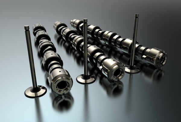
- Defective Camshaft Position Sensor
- Faulty wiring
- Improper air gap/installation
How Serious Is The P0341 Trouble Code?
P0341 is a severe trouble code. This code can cause your vehicle to stall or not run at all. The camshaft position sensor is a critical input to the ECM and should be diagnosed and repaired right away.
How To Diagnose And Fix The P0341 Code
- Use a scan tool to scan for trouble codes and record freeze frame data. If there are other codes related to camshaft or crankshaft timing, they can help diagnose P0341.
- Perform a thorough visual inspection of all related wiring. Check for any broken or chafed wiring, misrouted harnesses, and ensure that all connectors are tight and not corroded. Also, verify that the Camshaft Position Sensor is installed correctly and seated flush.
- Next, check the internal resistance of the sensor. To do this, set your DVOM to ohms and disconnect the connector for the Cam Sensor. Use a wiring diagram to test the resistance across the sensor signal terminal and the sensor ground terminal. If resistance is infinite or the circuit is open, the sensor should be replaced. If not, verify the specification in your service manual.
- If the sensor passes the resistance test, depending on your vehicle sensor’s circuit configuration, you may have a 5-volt reference signal. Check your wiring diagram and verify that this terminal has 5 volts coming from the ECM with the ignition key in the run position.
- The best way to verify the Camshaft Position Sensor signal is to use an oscilloscope to give yourself a signal’s visual waveform. But this is a relatively advanced diagnostic tool that most non-professional technicians are not able to use. You can get a rough idea of the signal health by checking it with your DVOM set to AC voltage, and reading in the millivolts indicates that the sensor is at least producing a signal.
- If none of these tests produce any results, you may be dealing with a valve timing issue. Some vehicles have not been appropriately maintained, such as not replacing a timing belt at the suggested interval or lack of oil changes on a vehicle equipped with a timing chain. The belt or chain has likely jumped teeth on one of its gears in those vehicles. You can check this by disassembling the engine enough to check the cam and crankshaft’s timing marks visually. Or using an oscilloscope to compare the cam and crank sensor signals.
Common Mistakes To Avoid While Diagnosing The P0341 Code
When diagnosing a P0341 trouble code, it is vital to make sure the wiring is routed correctly and not pulled too tightly or chafing on other components. Also, a faulty Crankshaft Position Sensor has been known to cause P0341 on certain vehicles. It is always a good idea to verify the Crankshaft Position Sensor operation when diagnosing a P0341.
Tips To Avoid P0341 In The Future
To help avoid P0341 in the future, always route wiring harnesses in their original position to avoid wires and connectors from being stretched or rubbing on other components. And following the manufacturer’s maintenance schedule will reduce the risk of having any actual valve train timing problems.
Read More: P2135 OBD2 Code: Meaning, Symptoms, Causes, Diagnostics, And Fixes
P1077 Honda Code: Insights Into A Common CR-V Issue
P1077 Honda Code: Insights Into A Common CR-V Issue
Encountering the code P1077 in your Honda vehicle? Don’t worry, you’re not alone. This common issue is frequently reported by many Honda owners, particularly CR-V models.
In this guide, we’ll explore the meaning, severity, symptoms, causes, and diagnostic steps for P1077 Honda. Whether you drive a CR-V or another Honda model, we’re here to provide valuable insights and guide you through the diagnostic process.
Let’s get started!!
P1077 Honda Code: Quick Summary
In Honda vehicles, the IMRC system, or the Intake Manifold Tuning (IMT) system, consists of several components working together. These include the intake manifold, IMRC valve, actuator, solenoid, and vacuum hoses.
Let’s take a quick look at the P1077 Honda code and what it entails:
- Definition: IMRC/ IMT System Malfunction (Low RPM)
- Severity: Medium
- DIY Skill Level: Intermediate
- Continue To Drive?: Yes (short-term)
- Estimated Repair Cost: $100-$500
Inside P1077 Honda: What Does It Mean?
The code P1077 is an OBD-II diagnostic trouble code that indicates a malfunction in the intake manifold runner control (IMRC) system. This system is designed to optimize engine performance by varying the intake runners’ length, which helps improve low-end torque and high-end power.
Under normal operating conditions, the ECM commands the IMRC system to adjust the length of the intake runners based on factors like engine speed, load, and temperature. This adjustment is crucial for optimizing airflow and enhancing overall engine performance.
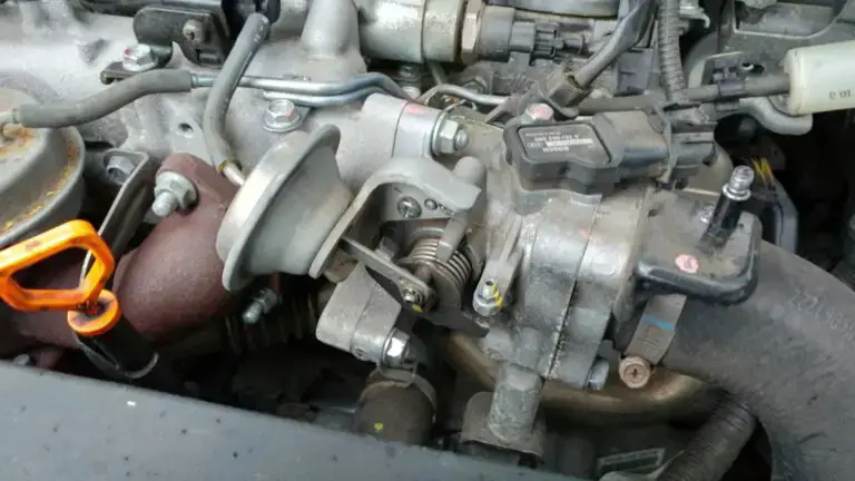
(Image credit: Civic Info forum)
However, when there is a malfunction in the IMRC system, the ECM detects an inconsistency between the desired and actual position of the intake manifold runners. This triggers the P1077 code, indicating that the system is not operating as intended.
It’s important to note that the P1077 code is commonly found in Honda CR-V and Civic models. These vehicles are known for their reliable performance and efficient engines. However, like any complex system, issues can arise over time, triggering diagnostic trouble codes such as P1077.
P1077 Honda Severity: Why Timely Action Is Essential
The P1077 code is classified as a moderate-level issue in terms of severity. While it may not pose an immediate threat to the vehicle’s or its occupants’ safety, it should not be ignored or left unaddressed.
So, should you continue to drive with this code? Yes, but for the short term only. Driving with the P1077 code present for an extended period can affect the engine’s performance and fuel efficiency. The malfunctioning IMRC system can lead to decreased power, reduced fuel economy, and potential drivability issues.
To prevent further damage and ensure optimal engine performance, addressing the P1077 code as soon as possible is advisable. By taking prompt action and resolving the P1077 code, you can ensure that your Honda continues to operate at its best and avoid any potential complications down the road.
Read more: Honda OBD2 Codes List
P1077 Honda Warning Signs
When encountering the P1077 code, several symptoms may manifest, alerting you to a potential issue with the IMRC system:
- Check Engine Light (CEL) illuminated
- Reduced engine power (especially under full throttle)
- Engine takes longer to shift from 2nd to 3rd
- Poor acceleration
- Rough idle
- Decreased fuel efficiency
Read more: Honda Dashboard Lights and Meaning (FULL list, Free Download)
What Triggers The P1077 Honda?
Several factors can contribute to the triggering of this code, including:
- Malfunctioning IMRC valve
- Defective intake manifold
- Vacuum leaks in the IMRC system
- Faulty IMRC actuator
- Wiring or electrical connection issues
- ECM software or programming glitches (rarely)
P1077 Honda Repair and Diagnosis
In this section, we will cover the essential tools and parts needed, provide a step-by-step procedure to diagnose and fix the P1077 code in a Honda CR-V, and discuss the level of DIY repair and estimated costs.
Attention: If you own a 2004 or 2005 CR-V, consult the TSB 05-052. It describes that the internal sticking of the IMT (IMRC) solenoid valve may trigger the P1077 code. Check if the symptoms described in the TSB match the observed problem. If yes, replacing the solenoid valve will solve the problem.
Essential Tools And Parts
To diagnose and repair the P1148 code, you may require the following tools and parts:
- Vacuum pump
- Scan tool
- Wiring harnesses and connectors
- Intake manifold (including runner, diaphragm, and sensor)
- Cleaning supplies for the intake ports
Step-by-Step Guide
Step 1: Perform Visual Inspection
- Open the hood and locate the engine’s intake manifold.
- Check if the vacuum hose linked to the intake manifold is connected correctly and receiving the vacuum.
Step 2: Check The Intake Manifold And Sensor Functionality
- Connect a vacuum pump to the intake manifold diaphragm while using a scan tool to monitor the sensor voltage.
- Repeat this process several times and observe if the sensor voltage readings are accurate and consistent. If the sensor readings are not correct, it indicates a problem.
Step 3: Test The Sensor
- Remove the intake runner sensor from the intake manifold.
- Manually move the sensor through its full range of motion to check for any glitches or abnormalities. Repair or replace the sensor if you find any faults.
- If the sensor moves smoothly without any issues, proceed to the next step.
Step 4: Check Wiring And Electrical Connections
- Inspect the wiring and connectors for the intake runner sensor, vacuum diaphragm assembly, and intake manifold.
- Look for any damage, loose connections, or corrosion. Test continuity with a multimeter and ensure secure connections.
Note: Working with electrical systems can be hazardous. Be careful!
Step 5: Inspect Vacuum Diaphragm Assembly And Intake Ports
- Remove the vacuum diaphragm assembly from the intake manifold.
- Inspect the assembly for any signs of oil inside it. If oil is present, it indicates an issue.
- With the intake manifold removed, check and clean the intake ports for carbon buildup.
Step 6: Replace The Intake Manifold
- Install the new intake manifold. Replacing the complete manifold (including a runner, diaphragm, and sensor) is recommended to prevent potential issues caused by the manifold warpage, which may lead to the new intake runner binding up.
- Test drive the vehicle.
Please note that the information provided above is a general guide. It’s always recommended to consult a qualified technician or refer to the vehicle’s specific repair manual, such as this DTC Troubleshooting Guide for P1077 on 2006 Honda CR-V, for detailed instructions and safety precautions.
DIY Repair Level And Estimated Costs
The repair procedure for the P1077 code requires intermediate to advanced mechanical skills. It involves disassembling and reassembling components of the intake manifold. If you are unsure or uncomfortable with these tasks, you should seek assistance from an expert mechanic.
The estimated cost for the main repair tasks may vary depending on labor rates and the parts needed. Here is a general breakdown of potential costs:
| Repair Tasks | Estimated Costs |
| Vacuum Hose Repair/Replacement | $20 – $50 |
| IMRC sensor | $100 – $200 |
| Wiring repair | $20 – $50 |
| New Intake Manifold | $100 – $499 |
Please note that these are approximate costs, and it is advisable to check with local suppliers and mechanics for more accurate pricing information.
Remember, if you are not confident in your abilities or lack the necessary tools, it is always best to consult a professional mechanic to ensure the proper diagnosis and repair of the P1077 code.
P1077 Honda Infographic
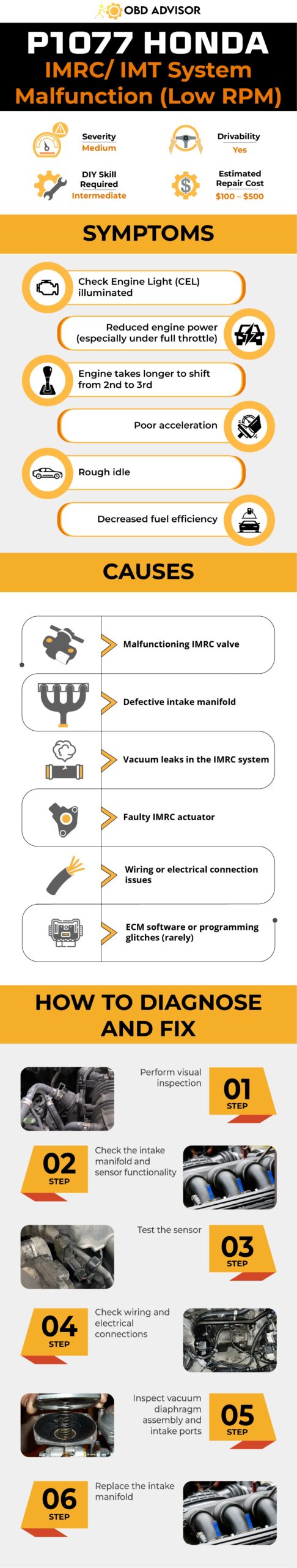
Wrapping Up
In conclusion, diagnosing and repairing the P1077 code in a Honda vehicle can be challenging. Still, it is achievable with the right tools, parts, and knowledge. Following the step-by-step procedure outlined in this section, you can effectively address the IMRC malfunction and resolve the illuminated MIL issue.
Remember, if you’re unsure or uncomfortable with the repair tasks involved, it’s always recommended to seek assistance from a professional mechanic.
If you found this information helpful, share it with others who might benefit. Feel free to leave a comment below with your thoughts or questions. Happy repairing!
Reference Sources
- Diagnostic Network, 2004 Honda CR-V Intermittent DTC — P1077 IMRC. Diagnostic Network.
- 2CarPros, Code P1077: I Have a Good Idle and All Hoses Hold Vacuum.
- MotoLogic, DTC Troubleshooting: P1077 • 2006 Honda CR-V.
P0299 – Turbocharger/Supercharger “A” Underboost Condition
P0299 – Turbocharger/Supercharger “A” Underboost Condition
The trouble code P0299 indicates that your vehicle’s turbo or supercharging system is creating an underboost condition. Generally, problems in your turbo/supercharger system should be taken seriously and repaired as soon as possible to prevent more serious and expensive engine damage. If you are experiencing a P0299, continue reading to learn more.
P0299 Definition
P0299 VW/Audi Definition: Boost Pressure Regulation, Control Range Not Reached
P0299 Ford Definition: Turbo/Supercharger Underboost Condition
P0299 Chevy Definition: Turbo/Supercharger Underboost Condition
What Does P0299 Mean?
On vehicles equipped with a turbo or supercharger, air entering the engine is compressed and generally cooled before entering the intake manifold. This feature allows the engine to create substantially more power than engines without turbo or superchargers. When you experience a P0299 trouble code, the ECM has determined that your forced induction system is not producing enough boost.
As the vehicle is working, incoming air is compressed and then forced into the intake manifold. This pressurized air is called a “boost” and is monitored and regulated by the PCM. The boost the PCM allows the turbo/supercharger to create varies due to different operating conditions and driver inputs. The PCM compares the amount of the desired boost to the amount of the actual boost. If the actual boost cannot reach the desired level, the check engine light will be illuminated, and the car may enter “limp mode.”
What Are The Symptoms Of The P0299 Code?
The P0299 code will usually be accompanied by a few noticeable symptoms that include:
- Activation of the check engine light
- Low engine power
- Unusual engine noises
- Black smoke from the exhaust
What Are The Causes of P0299?
- Failed turbo or supercharger
- Intake air/book leak
- Vacuum leak
- MAP or boost pressure sensor failure
- Turbocharger wastegate and/or solenoid failure
How Serious Is The P0299 Code?
P0299 is a serious code. Failure to properly diagnose and repair the air induction system on a turbo or supercharged vehicle can potentially result in severe and expensive engine damage. It is common for a turbocharger to fail internally and cause scraps of metal to be introduced into the engine.
How To Diagnose And Fix The P0299 Code
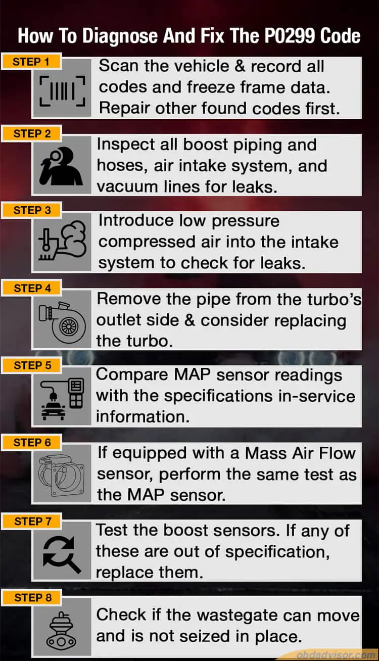
Diagnosing a P0299 can vary widely from make to make, so consulting a service manual with vehicle specific information is highly recommended. But here are some general guidelines to follow.
- Scan the vehicle with a scan tool and record all codes and freeze frame data. If there are any other codes related to engine performance, including EGR, repair them first.
- Next, perform a thorough visual inspection of all boost piping and hoses, air intake system, and vacuum lines. Make sure all clamps are tight and properly positioned. If any leaks are found, repair or replace the component.
- If no leaks are visible, it may be necessary to use a smoke machine or introduce low pressure compressed air into the intake system to check for leaks.
- Once you have verified there are no leaks, remove the pipe from the turbo’s outlet side and look at the wheel/shaft for excessive side to side or up and down movement. Ensure the turbo has had time to cool off before touching, as it gets very, very hot during normal operation. If there are any signs of damage, you should replace the turbo.
- Use a scan tool to compare MAP sensor readings at idle and at 2500RPM with the specifications in-service information.
- If equipped with a Mass Air Flow sensor, perform the same test as the MAP sensor.
- Certain cars come equipped with a boost sensor that should also be tested using the correct service information. If any of these are out of specification, replace them.
- Check to make sure that the wastegate of capable of moving and is not seized in place. These are typically vacuum or electronically controlled. Again, consult service information. If it is vacuum controlled, ensure that the control solenoid has a steady vacuum with the engine running. Use a scan tool to perform a functional test of the vacuum solenoid to verify that the solenoid can open and close and the PCM is capable of controlling it.
Please use the above steps as a general guideline for diagnosis. The forced induction systems used by different vehicles make dramatic differences, so it would be impossible to cover each vehicle specific test in the space provided.
Common Mistakes To Avoid While Diagnosing The P0299 Code
Remember to check the engine air filter, and a dirty filter could not allow enough air into the intake system, causing a low boost condition. Also, on some cars, a fault in the EGR system can cause P0299, so repair EGR issues first. And, remember, just because you can’t see a leaking air pipe or hose with the engine off doesn’t mean it isn’t leaking under boost pressures.
Tips To Avoid P0299 In The Future
As usual, proper maintenance is key! Make sure to change your oil using the appropriate oil viscosity and specifications. The engine oil also lubricates your turbo/supercharger, so this is very important. Please do your best to keep rodents out of your engine bay, as they tend to destroy vacuum lines and electrical wires. And before shutting off your car, let it idle for a minute or two to allow the turbo to cool before cutting off its oil supply when shutting down the engine.
Read More: Procharger vs. turbocharger vs. supercharger: Which is best for me?
P1778 Nissan Code: Fix The Step Motor Malfunction!
P1778 Nissan Code: Fix The Step Motor Malfunction!
If you’re driving a Nissan with a CVT (Continuously Variable Transmission), you might be all too familiar with the challenges that can arise. One particular problem that can occur is the triggering of the frustrating P1778 code.
The P1778 Nissan code is directly related to the step motor within the CVT and can signal a range of issues affecting its performance. This article will provide clear explanations about the code and offer effective solutions.
Let’s delve into the details of the P1778 Nissan together.
P1778 Nissan: An Overview
Let’s take a quick look at the essential details of the P1778 Nissan code!
- Definition: Step Motor Function
- Severity: Medium
- DIY Skill Level: Intermediate
- Continue To Drive?: Yes
- Estimated Repair Cost: $30 – $200
What Does P1778 Mean In Nissan Vehicles?
The P1778 code in Nissan vehicles specifically refers to a problem in the Step Motor Function or its circuit within the CVT system. This code is commonly triggered in Nissan models such as the Altima, Murano, Rogue, Sentra, and Maxima.
The CVT system in Nissan vehicles relies on a step motor, also known as a stepper motor, to control the movement of the ratio control valve, which is responsible for regulating hydraulic pressure and selecting the appropriate gear ratio.
The P1778 code is specifically triggered when the TCM detects that the pulley ratio is not changing properly to match values commanded by TCM, resulting from the mechanical failure of the step motor.
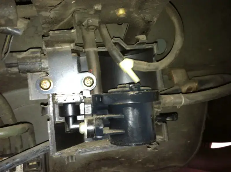
(Image credit: nissanmurano.org)
It is worth mentioning that Nissan has taken steps to address the P1778 code issue through various recall campaigns. For instance, in 2013, there was a recall – the SB-10038184-2435 TSB, specifically for the 2010 Maxima, Murano, and V6 Altima models.
When encountering the P1778 code, the first step is to check for any related Technical Service Bulletins (TSBs) from Nissan. These TSBs contain valuable information and recommended actions for specific vehicle models. By consulting the relevant TSB for your specific car, you can determine if your vehicle falls under a recall campaign or if there are particular actions you should take to address the P1778 code.
Read more: P1777 Nissan Code: Step Motor Circuit
Special Note Regarding P1778 Nissan Code – Transmission Reverse I/P Circuit Fault
The P1778 Nissan code can have different definitions depending on the car model. The most common definition, which this article focuses on, relates to the Step Motor Function within the CVT system. However, it’s worth noting that this code may be defined as a Transmission Reverse I/P (Input/Output) Circuit fault in certain car models.
This fault occurs when there is a discrepancy between the number of steps for the stepping motor and the actual gear ratio. It is a functional code, rather than a circuit code, for the step motor.
Unfortunately, this issue is often caused by a failing CVT transmission. However, there is some positive news to consider. Nissan has introduced an extended warranty for 10 years and 120,000 miles on the CVT of certain models. Consult with your nearest Nissan dealership or authorized service center for more information if you’re experiencing the Transmission Reverse I/P Circuit fault code.
How Serious Is The Nissan P1778 Code?
The severity level of the P1778 code in Nissan vehicles can be considered medium. It does not pose an immediate safety risk or cause the vehicle to become inoperable. Therefore, it is generally safe to continue driving with this code present.
However, it is essential to address the issue as soon as possible to prevent further damage to the transmission and ensure optimal vehicle performance. Ignoring the code for an extended period may lead to transmission-related problems, such as erratic shifting or reduced fuel efficiency.
Read more: Nissan OBD1/OBD2 Codes List
Common Symptoms Of P1778 In Nissan Vehicles
Common symptoms of the P1778 code in Nissan vehicles include:
- Check Engine Light (CEL) or Malfunction Indicator Lamp (MIL) illuminated
- Transmission problems or abnormalities such as:
- Difficulty with light acceleration
- Unresponsive throttle when starting from a stop
- Failure to engage into gear or move
- Transmission stuck in safe mode
Read more: Nissan Dashboard Warning Lights List
Exploring The Causes Behind P1778 Nissan Code
The P1778 code in Nissan vehicles is often caused by:
- Faulty step motor
- Open or shorted step motor harness
- Poor wiring and connection in the step motor circuit
How to Diagnose And Repair P1778 In Your Nissan
Dealing with the P1778 code can be a real headache, especially when service advisors start talking about replacing your entire transmission and the costs pile up.
But here’s the truth: you may not need to break the bank. By taking care of your CVT fluid and addressing the step motor, you can often tackle the issue without draining your wallet.
Dive in and explore the steps to diagnose and repair P1778 in your Nissan, saving you some hard-earned cash.
Essential Tools And Parts
- OBD-II scanner
- Basic hand tools (wrenches, sockets, etc.)
- Multimeter
- Nissan CVT transmission fluid
- Transmission cooler
- Step Motor (if necessary)
Step-by-Step Procedure
Step 1: Retrieve trouble codes
Connect an OBD-II scanner to the vehicle’s diagnostic port and retrieve any trouble codes. Check if there are any associated codes and prioritize addressing them first.
Step 2: Check the CVT fluid
Ensure the CVT fluid level is within the recommended range when the transmission is cold. If it is too high, drain some fluid to bring it to the correct level.
Inspect the CVT fluid. If it appears worn out or there are signs of aeration or contamination, you can either perform a transmission fluid flush yourself or consider having the CVT fluid professionally flushed and replaced.
Step 3: Inspect the trans cooler
Check the transmission cooler for any signs of damage or blockage that could affect fluid flow and cooling. Repair or replace if necessary.
Step 4: Inspect the step motor harness
Check for any damage or loose connections in the step motor harness. Repair if required.
Step 5: Test the step motor
Use a multimeter to test the step motor for proper voltage and continuity. Replace the Step Motor with a new one if necessary.
Step 6: Clear trouble codes and test drive
Use the OBD-II scanner to clear the trouble codes. Take the vehicle for a test drive to ensure that the code does not reappear and that the transmission functions appropriately.
Note: It’s important to refer to the vehicle’s service manual for detailed instructions and specifications during the process.
DIY Repair Level And Estimated Costs
Diagnosing the P1778 code can be done by an experienced DIYer, as it involves basic diagnostic procedures using common tools. However, replacing the step motor may require intermediate mechanical skills. It is recommended to consult the vehicle’s service manual for specific instructions.
Below is a breakdown of the main repair tasks and their estimated costs for repairing the P1778 Nissan code:
| Repair Task | Cost Range |
| Diagnostic Fee | $50 – $150 |
| Wiring repair | $50 – $200 |
| CVT fluid replacement | $50 – $200 |
| Step motor replacement | $50 – $150 (part and labor) |
Please note that these are rough estimates, and costs can vary depending on factors such as the vehicle model, location, and quality of parts. If you’re unsure about the diagnosis or repair process, it’s recommended to consult with an automotive professional or mechanic to ensure an accurate diagnosis and proper repairs are performed.
Wrapping Up
In conclusion, if you encounter the P1778 code in your Nissan vehicle, it’s crucial to take action and address it promptly. Ignoring the code can lead to potential transmission issues and increased repair costs. To resolve the problem, seek assistance from a qualified professional or consult your vehicle’s service manual for proper diagnosis and repair guidance.
If you’ve had any experiences or have questions about the P1778 code or any other OBD codes, we’d be thrilled if you could share them in the comments below.
Safe travels and happy fixing!
Reference Sources
- Nissan USA, Xtronic CVT (Continuously Variable Transmission).
- CarParts, Why the Nissan CVT Is Quite Possibly the Worst Transmission Ever Built.
- Pickup Truck Talk, How Reliable Is the Nissan CVT?.
P0113: Intake Air Temperature Sensor 1 Circuit High
P0113: Intake Air Temperature Sensor 1 Circuit High
What does the P0113 code mean?
Can you continue to drive your car with it, and what are the aftereffects?
Here is a quick evaluation of the problem!
- P0113 Definition: Intake Air Temperature Sensor 1 Circuit High
- Code type: Generic – P0113 indicates the same problem whether you’re having a Ford, Honda, or Toyota, etc.
- Can I Drive with the P0113 code? Yes. It is not severe, and the car is safe to drive.
- Easy to fix? Intermediate-advanced level.
- Cost: $50-$200 (common)
Read on for detailed information about what P0113 is, its causes, and how to identify and fix it.
What Does The P0113 Code Mean?
P0113 is a diagnostic trouble code (DTC) for “Intake Air Temperature Sensor 1 Circuit High”.
The car’s computer sets this code if it detects the Intake Air Temperature (IAT) sensor’s voltage is higher than 4.6V.
This number tells the computer that the intake air temperature is abnormally low (40°F.)
How Do IAT Sensors Work?
An IAT sensor provides the temperature of the air going to the engine.
The combination of air temperature and air volume indicates air mass.
Based on the data received, PCM adjusts fuel added to the air-fuel ratio.
The colder the air gets, the heavier it becomes and the higher the IAT output voltage.
The voltage usually ranges from 0.5 to 4.5.
What Will Happen When P0113 Is Set?
If the IAT sensor is missing, the data is 4.6V (- 40°F). That tells the PCM that the temperature is cold (but it’s not). The computer doesn’t believe in that information and enters the Failsafe mode to avoid engine damage.
Instead of working with the incorrect data, the computer chooses a constant number to believe in. Usually, most cars will pick 100°F. This allows the engine to run optimally and with minimal damage.
If the actual intake air temperature goes below 100°F, the air is colder than what the computer knows. That causes more air to be sucked into the engine, which results in a lean condition.
On the other hand, an actual intake air temperature above 100°F makes the air hotter. That means less air gets in the engine, leading to a rich condition.
None of these conditions are desirable.
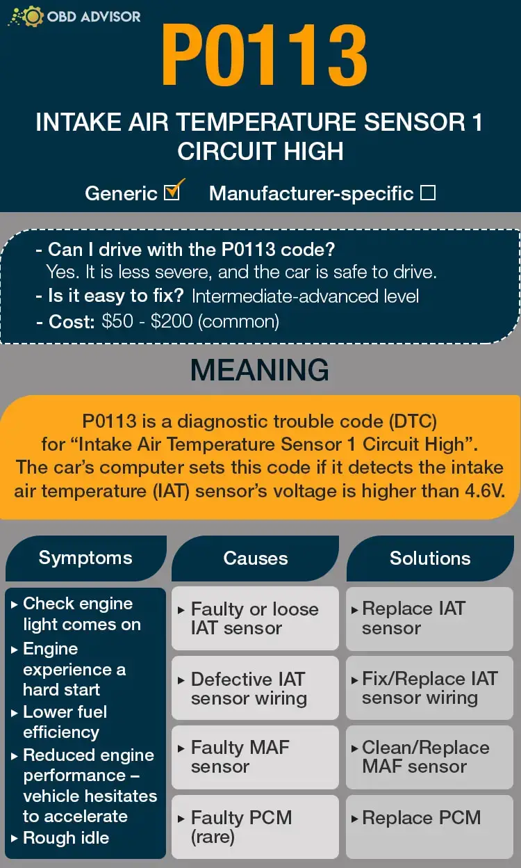
P0113: Causes, Symptoms, And How To Fix
Symptoms
P0113 will show the following common symptoms:
- Check engine light comes on
- Engine experience a hard start
- Lower fuel efficiency
- Reduced engine performance – vehicle hesitates to accelerate
- Rough idle
Causes
There are only three main causes for the P0113.
Cause #1: Faulty Or Loose IAT Sensor
If the IAT sensor is faulty or loose, it will be sending incorrect data to PCM. The PCM detects that and sets the P0113 code.
The solution is to replace the faulty IAT sensor or make it tighter in its socket if that was the cause of the malfunction.
Cause #2: Defective IAT Sensor Wiring
IAT sensor data goes to PCM through the signal wire. An open signal circuit will lead to high IAT voltage output.
Check the IAT sensor circuit for open, or loose wires and fix them accordingly. Damaged ones should be replaced.
Cause #3: Faulty MAF Sensor
Some vehicles have the IAT attached to the Mass Air Flow (MAF) sensor. So, when the MAF is gone, the IAT is gone.
In this case, if the MAF is bad, cleaning or replacing the MAF may fix P0113.
Cause #4: Faulty PCM (rare)
PCM rarely becomes faulty and this should be your last conclusion. The most common problem is a bug in its software or damage resulting from a short circuit, lightning, or impact.
Replacing the PCM is the best option in this case.
This is a complicated and expensive procedure so you may need a qualified automotive technician to help you.
P0113 Causes Identification: How to Diagnose
Solving the P0113 code problem involves diagnosing the causes, one after the other, and eliminating them. Proceed as follows:
Check The IAT Sensor
Start by visually inspecting the IAT sensor for loose terminal connections and dirt. If that is the case, tighten and clean everything.
The next step is to test the resistance across the IAT sensor terminals. If you get infinity resistant or OL (out of limit) reading, it is faulty. So, replace it.
In case the IAT is attached to the MAF, locate the IAT thermistor and repeat the above process.
Check IAT Sensor Wiring
Use an OBD2 scanner to view the live data from the IAT sensor with the sensor removed from its socket. The reading should be -40°F.
Repeat the process, but this time short the two pins with a jumper wire. The new value should be maxed out (around 285°F). That shows the IAT sensor wiring has no problems.
If you get different values, there is an issue with the IAT sensor wiring. So, use a wire tracker to find where it is open and fix it appropriately.
Check PCM
After checking both the sensor and its wiring, if they are not the problem, it can be because of the PCM.
9 out of 10 times, the IAT sensor or its wiring will reveal itself as the problem when you perform the above diagnosis. If it’s not, having a mechanic inspect your PCM is the next thing you should do.
How Much Does It Cost To Fix The Code P0113?
The cost of fixing the P0113 code varies depending on your car’s make, model, and year. Also, the part to be replaced influences the price tag.
The most common problem is a faulty IAT sensor, which typically costs $20-$150 to replace by yourself.
The Estimated Repair Cost Of P0113
| Solutions | Repair cost |
|---|---|
| Replace the IAT sensor | DIY: $20-$150 Mechanic: $40-$250 |
| Fix IAT sensor wiring | DIY: $0-$20 Mechanic: $20-$75 |
| Replace MAF sensor | DIY: $30 to $300 Mechanic: $80 to $380 |
| Replace PCM | DIY: not recommended Mechanic: $1,000-$3,000 |
Note: The data in this table was collected in June 2022. The actual price depends on many factors, such as your car’s make and year, mechanic’s rate, etc.
You Ask, I Answer
The P0113 code should not make you panic. Your car should still be drivable if it has the failsafe feature, and the cost of fixing it is relatively low, about $20-$150 for replacing the IAT sensor.
Do you have any hands-on experience with the P0113 code? How did you fix it? How much and how long did it take you? Let us know your responses in the comments.
See ya!
Read more: The 9 Best OBD2 Scanners for 2024: The Only Review You Need
P068A Code: Symptoms, Causes, and Solutions
P068A Code: Symptoms, Causes, and Solutions
The P068A code flashing on your vehicle’s diagnostics can be confusing, but we’re here to provide clarity and solutions.
In this guide, we’ll shed light on the P068A code, explain what it means, outline common symptoms, and pinpoint potential causes. Most importantly, we’ll walk you through the steps to diagnose and resolve the issue effectively.
Whether you’re a hands-on car enthusiast or someone seeking straightforward answers, this guide equips you with the knowledge to tackle the P068A code confidently and ensure your vehicle operates smoothly.
Let’s get started!
P068A Code: A Quick Summary
Definition: ECM / PCM Power Relay De-Energized Performance – Too Early
Severity: High
DIY Skill Level: Intermediate
Continue To Drive?: No
Estimated Repair Cost: $50 – $700
What Does the P068A Code Mean?
The P068A DTC is like a warning sign from your car’s computer. It’s a way for your vehicle to communicate that something might not be quite right with the engine or powertrain. Essentially, this code points to an issue related to the power relay in the engine control module (ECM) or powertrain control module (PCM).
In simple terms, it means that the computer in your car is having trouble with the electricity it needs to work correctly. More specifically, it’s concerned about how quickly the power relay turns off after you switch off the ignition. If it happens too fast, it can potentially harm the module.
The P068A DTC can be found in various car makes and models. It’s not specific to just one brand. You might come across this code in vehicles from manufacturers like Ford, Volkswagen, Chevrolet, Toyota, Honda, and many others. It’s not picky about which car it appears in!
How Serious is the P068A Code?
The P068A code indicates a moderate to high severity issue. Driving with a P068A code is not advisable. It can be risky as your engine may stall unexpectedly, especially in traffic or on highways.
Moreover, ignoring this issue can result in more extensive and costly damage to your vehicle’s electrical system. To ensure your safety and prevent further damage, it’s recommended to have your vehicle inspected and repaired by a qualified mechanic as soon as possible when this code appears.
What are the Symptoms of the P068A Code?
Experiencing symptoms related to the P068A code? Here’s what you might notice:
- Illuminated Check Engine Light
- Difficulty starting the vehicle, especially in winter
- Engine stalling
What are the Causes of the P068A Code?
The P068A code can be triggered by several underlying issues. Common causes include:
- Faulty PCM/ECM power relay
- Damaged wiring or connectors in the power relay circuit
- Problems with the PCM/ECM itself
How To Diagnose and Repair P068A Code?
When dealing with the P068A code, it’s essential to have the right tools and parts, and a comprehensive guide for an effective diagnosis and repair. In this section, I’ll give you all.
Diagnostic Tools and Essential Parts
- OBD-II scanner for code reading and clearing
- Multimeter for electrical testing
- Wiring diagram for your vehicle
- Replacement PCM/ECM power relay (if required)
- Wiring repair kit (if wiring issues are detected)
Step-by-Step Guide
- Begin by connecting the OBD-II scanner to your vehicle’s diagnostic port and retrieve the P068A code.
- Inspect the PCM/ECM power relay for signs of damage or wear. If it’s faulty, replace it.
- Examine the wiring and connectors in the power relay circuit. Look for frayed wires or loose connections. Repair or replace as necessary.
- Clear the code and rescan to see whether the code reappears or not. If it is set again, proceed to step 5.
- Test the PCM/ECM to ensure it’s functioning correctly. If it’s found to be the issue, it may need professional reprogramming or replacement. Ensure the car operates properly after PCM replacement.
Note:
- Always disconnect the vehicle’s battery before working on electrical components.
- Refer to the wiring diagram specific to your vehicle for accurate testing.
- If you’re unsure about any step or lack experience with electrical systems, consider consulting a professional mechanic.
Read more: C1201 Toyota Code: How To Tackle Engine Control Problems
DIY Repair Level and Estimated Costs
This repair falls into the intermediate to advanced DIY category. Replacing the PCM/ECM power relay and addressing wiring issues can be tackled by experienced DIYers. However, you should find a professional to diagnose and replace the PCM/ECM.
The estimated costs for fixing the P068A code can vary depending on the specific cause and the vehicle’s make and model. Here is a rough cost estimate for common repair tasks:
| Repair Task | Estimated Cost |
| PCM/ECM power relay replacement | $50 – $150 |
| Wiring Issues Repair | $50 – $150 |
| PCM/ECM replacement and reprogramming | $500 – $1500 |
Conclusion
In wrapping up, understanding the P068A code is the first step in addressing potential issues with your vehicle’s PCM/ECM power relay control circuit. Driving with this code can pose risks to both your safety and your vehicle’s health. If you’ve experienced any of the listed symptoms, it’s wise to consult a qualified mechanic for a proper diagnosis and timely repair.
Have you or someone you know encountered the P068A code? Share your experiences and insights in the comments below. If you found this article helpful, don’t hesitate to share it with others who might benefit from this information. Safe driving, everyone!
Reference Sources
YourMechanic, Symptoms of a Bad or Failing ECM Power Relay.
Nissan Trouble Codes: Comprehensive List For OBD1/OBD2
Nissan Trouble Codes: Comprehensive List For OBD1/OBD2
Get ready for an exciting journey into the world of Nissan trouble codes!
In this engaging article, we’ll delve deep into the intricacies of OBD1 and OBD2 codes, equipping you with valuable information to help you tackle automotive challenges head-on.
So, let’s rev up our engines and dive into this post filled with knowledge and expertise!
Nissan OBD1 Codes List And Definition [FULL]
Free download: Full Nissan OBD1 Trouble Codes List and Meaning PDF
Note: Use the search box in the table below to quickly find the specific code you’re looking for.
| Code | Definition |
|---|---|
| Code 11 | Crank Angle Sensor/Camshaft Position Sensor |
| Code 12 | Air Flow Meter/Mass Air Flow Sensor |
| Code 13 | Engine Coolant Temperature Sensor |
| Code 14 | Vehicle Speed Sensor |
| Code 21 | Ignition Signal |
| Code 22 | Fuel Pump |
| Code 23 | Idle Switch |
| Code 24 | Throttle Valve Switch |
| Code 25 | Idle Speed Control Valve |
| Code 28 | Cooling Fan Circuit |
| Code 31 | ECM |
| Code 32 | EGR Function |
| Code 33 | Heated Oxygen Sensor |
| Code 34 | Knock Sensor |
| Code 35 | Exhaust Gas Temperature Sensor |
| Code 36 | EGR Control-Back Pressure Transducer |
| Code 37 | Knock Sensor |
| Code 38 | Right hand bank Closed Loop (B2) |
| Code 41 | Intake Air Temperature Sensor |
| Code 42 | Fuel Temperature Sensor |
| Code 43 | Throttle Position Sensor |
| Code 44 | ECCS Normal Operation |
| Code 45 | Injector Leak |
| Code 47 | Crankshaft Position Sensor |
| Code 51 | Injector Circuit |
| Code 53 | Oxygen Sensor |
| Code 54 | A/T Control |
| Code 55 | No Malfunction |
| Code 63 | No 6 Cylinder Misfire |
| Code 64 | No 5 Cylinder Misfire |
| Code 65 | No 4 Cylinder Misfire |
| Code 66 | No 3 Cylinder Misfire |
| Code 67 | No 2 Cylinder Misfire |
| Code 68 | No 1 Cylinder Misfire |
| Code 71 | Random Misfire |
| Code 72 | TWC Function right hand bank |
| Code 73 | TWC Function right hand bank |
| Code 76 | Fuel Injection System Function right hand bank |
| Code 77 | Rear Heated Oxygen Sensor Circuit |
| Code 82 | Crankshaft Position Sensor |
| Code 84 | A/T Diagnosis Communication Line |
| Code 85 | VTC Solenoid Valve Circuit |
| Code 86 | Fuel Injection System Function right hand bank |
| Code 87 | Canister Control Solenoid Valve Circuit |
| Code 91 | Front Heated Oxygen Sensor Heater Circuit right hand bank |
| Code 94 | TCC Solenoid Valve |
| Code 95 | Crankshaft Position Sensor |
| Code 98 | Engine Coolant Temperature Sensor |
| Code 101 | Front Heated Oxygen Sensor Heater Circuit right hand bank |
| Code 103 | Park/Neutral Position Switch Circuit |
| Code 105 | EGR and EGR Canister Control Solenoid Valve Circuit |
| Code 108 | Canister Purge Control Valve Circuit |
Nissan OBD2 Codes List And Definition [Free Download]
Free download: Full Nissan OBD2 Trouble Codes List and Meaning PDF
Our extensive Nissan OBD2 codes list is your ultimate companion, covering Powertrain, Network, Body, and Chassis issues. This intuitive resource simplifies your search for engine, network, body control, and chassis-related codes.
Note: Use the search box in the table below to quickly find the specific code you’re looking for.
Powertrain (P) Codes List
| Code | Definition |
|---|---|
| P0002 | Fuel Volume Regulator Control Circuit Range/Performance |
| P0003 | Fuel Volume Regulator Control Circuit Low |
| P0006 | Fuel Shutoff Valve “A” Control Circuit Low |
| P0010 | “A” Camshaft Position Actuator Circuit (Bank 1) |
| P0011 | Camshaft position (CMP), intake/left/front, bank 1 timing over advanced/system performance |
| P0011 | “A” Camshaft Position – Timing Over-Advanced or System Performance (Bank 1) |
| P0012 | “A” Camshaft Position – Timing Over-Retarded (Bank 1) |
| P0014 | “B” Camshaft Position – Timing Over-Advanced or System Performance (Bank 1) |
| P0016 | Crankshaft Position – Camshaft Position Correlation (Bank 1 Sensor A) |
| P0021 | Intake Valve Timing Control Performance Bank 2 |
| P0021 | “A” Camshaft Position – Timing Over-Advanced or System Performance (Bank 2) |
| P0022 | “A” Camshaft Position – Timing Over-Retarded (Bank 2) |
| P0024 | “B” Camshaft Position – Timing Over-Advanced or System Performance (Bank 2) |
| P002A | B Camshaft Profile Control Circuit/Open Bank 1 |
| P0031 | Oxygen (A/F) Sensor Heater Control Circuit Low (Bank 1 Sensor 1) |
| P0032 | Oxygen (A/F) Sensor Heater Control Circuit High (Bank 1 Sensor 1) |
| P0037 | HO2S Heater Control Circuit Low (Bank 1 Sensor 2) |
| P0038 | HO2S Heater Control Circuit High (Bank 1 Sensor 2) |
| P0043 | HO2S Heater Control Circuit Low (Bank 1 Sensor 3) |
| P0044 | HO2S Heater Control Circuit High (Bank 1 Sensor 3) |
| P004F | Turbocharger/Supercharger Boost Control “B” Circuit Intermittent/Erratic |
| P0051 | Oxygen (A/F) Sensor Heater Control Circuit Low (Bank 2 Sensor 1) |
| P0052 | Oxygen (A/F) Sensor Heater Control Circuit High (Bank 2 Sensor 1) |
| P0057 | HO2S Heater Control Circuit Low (Bank 2 Sensor 2) |
| P0058 | HO2S Heater Control Circuit High (Bank 2 Sensor 2) |
| P005F | Turbocharger/Supercharger Boost Control B Supply Voltage Circuit High |
| P0068 | MAP/MAF – Throttle Position Correlation |
| P006A | MAP – Mass or Volume Air Flow Correlation Bank 1 |
| P0075 | Intake Valve Control Solenoid Circuit (Bank 1) |
| P0078 | Exhaust Valve Control Solenoid Circuit (Bank 1) |
| P0081 | Intake Valve Control Solenoid Circuit (Bank 2) |
| P0084 | Exhaust Valve Control Solenoid Circuit (Bank 2) |
| P0085 | Exhaust Valve Control Solenoid Circuit Low (Bank 2) |
| P0086 | Exhaust Valve Control Solenoid Circuit High (Bank 2) |
| P0087 | Fuel Rail/System Pressure – Too Low |
| P0088 | Fuel Rail/System Pressure – Too High |
| P0090 | Fuel Pressure Regulator 1 Control Circuit Open |
| P00A6 | Intake Air Temperature (IAT) Sensor 2 Circuit Range/Performance Bank 2 |
| P00A9 | Intake Air Temperature Sensor 2 Circuit Intermittent Bank 2 |
| P0100 | Mass or Volume Air Flow (MAF) Circuit Malfunction |
| P0101 | Mass Air Flow Circuit Range/Performance |
| P0101 | Mass Air Flow (MAF) Circuit Range/Performance |
| P0102 | Mass or Volume Air Flow Circuit Low |
| P0103 | Mass or Volume Air Flow Circuit High |
| P0105 | Manifold Absolute Pressure/Barometric Pressure Circuit Malfunction |
| P0106 | Manifold Absolute Pressure/Barometric Pressure Circuit Range/Performance Problem |
| P0107 | Manifold Absolute Pressure/Barometric Pressure Circuit Low Input |
| P0108 | Manifold Absolute Pressure/Barometric Pressure Circuit High Input |
| P010A | Mass or Volume Air Flow “B” Circuit Malfunction |
| P010B | Mass Air Flow (MAF) “B” Circuit Range/Performance |
| P010C | Mass or Volume Air Flow “B” Circuit Low |
| P010D | Mass or Volume Air Flow “B” Circuit High |
| P0110 | Intake Air Temperature Sensor 1 Circuit Malfunction |
| P0111 | Intake Air Temperature (IAT) Sensor 1 Circuit Range/Performance |
| P0112 | Intake Air Temperature Sensor 1 Circuit Low Input |
| P0113 | Intake Air Temperature Sensor 1 Circuit High Input |
| P0115 | Engine Coolant Temperature Sensor Circuit Malfunction |
| P0116 | Engine Coolant Temperature (ECT) Sensor Circuit Range/Performance |
| P0117 | Engine Coolant Temperature (ECT) Sensor Circuit Low Input |
| P0118 | Engine Coolant Temperature Sensor Circuit High Input |
| P011B | Engine Coolant Temperature/Intake Air Temperature Correlation |
| P011C | Charge Air Temperature/Intake Air Temperature Correlation Bank 1 |
| P011D | Charge Air Temperature/Intake Air Temperature Correlation Bank 2 |
| P0120 | Throttle Position Sensor/Switch (TPS) A Circuit Malfunction |
| P0121 | Throttle Position Sensor/Switch A Circuit Range/Performance Problem |
| P0122 | Throttle Position Sensor/Switch A Circuit Low Input |
| P0123 | Throttle Position Sensor/Switch A Circuit High Input |
| P0125 | Insufficient Coolant Temperature For Closed Loop Fuel Control |
| P0127 | Intake Air Temperature Too High |
| P0128 | Coolant Thermostat (Coolant Temperature Below Thermostat Regulating Temperature) |
| P0130 | O2 Sensor Circuit Malfunction (Bank 1 Sensor 1) |
| P0131 | Oxygen O2 Sensor Circuit Low Voltage (Bank 1, Sensor 1) |
| P0132 | O2 Oxygen Sensor Circuit High Voltage (Bank1, Sensor1) |
| P0133 | Oxygen Sensor Circuit Slow Response (Bank1, Sensor1) |
| P0134 | O2 Sensor Circuit No Activity Detected (Bank 1 Sensor 1) |
| P0135 | Oxygen O2 Sensor Heater Circuit Malfunction (Bank 1, Sensor 1) |
| P0136 | Oxygen O2 Sensor Circuit Low Voltage (Bank 1, Sensor 2) |
| P0137 | Oxygen O2 Sensor Circuit Low Voltage (Bank 1, Sensor 2) |
| P0138 | O2 Oxygen Sensor Circuit High Voltage (Bank1, Sensor2) |
| P0139 | Oxygen Sensor Circuit Slow Response (Bank1, Sensor2) |
| P0140 | O2 Sensor Circuit No Activity Detected (Bank 1 Sensor 2) |
| P0141 | O2 Sensor Heater Circuit Malfunction (Bank 1, Sensor 2) |
| P0143 | O2 Sensor Circuit Low Voltage (Bank 1 Sensor 3) |
| P0144 | O2 Sensor Circuit High Voltage (Bank 1 Sensor 3) |
| P0145 | O2 Sensor Circuit Slow Response (Bank 1 Sensor 3) |
| P0146 | O2 Sensor Circuit No Activity Detected (Bank 1 Sensor 3) |
| P0147 | O2 Sensor Heater Circuit Malfunction (Bank 1 Sensor 3) |
| P014C | O2 Sensor Slow Response – Rich to Lean (Bank 1 Sensor 1) |
| P014D | O2 Sensor Slow Response – Lean to Rich (Bank 1 Sensor 1) |
| P014E | O2 Sensor Slow Response – Rich to Lean (Bank 2 Sensor 1) |
| P014F | O2 Sensor Slow Response – Lean to Rich (Bank 2 Sensor 1) |
| P0150 | O2 Sensor Circuit Malfunction (Bank 2 Sensor 1) |
| P0151 | Oxygen O2 Sensor Circuit Low Voltage (Bank 2, Sensor 1) |
| P0152 | O2 Sensor Circuit High Voltage (Bank 2 Sensor 1) |
| P0153 | Oxygen Sensor Circuit Slow Response (Bank2, Sensor1) |
| P0154 | O2 Sensor Circuit No Activity Detected (Bank 2 Sensor 1) |
| P0155 | O2 Sensor Heater Circuit Malfunction (Bank 2 Sensor 1) |
| P0156 | O2 Sensor Circuit Malfunction (Bank 2 Sensor 2) |
| P0157 | O2 Sensor Circuit Low Voltage (Bank 2 Sensor 2) |
| P0158 | O2 Sensor Circuit High Voltage (Bank 2 Sensor 2) |
| P0159 | Oxygen Sensor Circuit Slow Response (Bank2, Sensor2) |
| P015A | O2 Sensor Delayed Response – Rich to Lean (Bank 1 Sensor 1) |
| P015B | O2 Sensor Delayed Response – Lean to Rich (Bank 1 Sensor 1) |
| P015C | O2 Sensor Delayed Response – Rich to Lean (Bank 2 Sensor 1) |
| P015D | O2 Sensor Delayed Response – Lean to Rich (Bank 2 Sensor 1) |
| P0160 | O2 Sensor Circuit No Activity Detected (Bank 2 Sensor 2) |
| P0161 | Oxygen O2 Sensor Circuit Low Voltage (Bank 2, Sensor 2) |
| P0170 | Fuel Trim Malfunction (Bank 1) |
| P0171 | System Too Lean (Bank 1) |
| P0172 | System Too Rich (Bank 1) |
| P0174 | System Too Lean (Bank 2) |
| P0175 | System Too Rich (Bank 2) |
| P0180 | Fuel Temperature Sensor A Circuit Malfunction |
| P0181 | Fuel Temperature Sensor A Circuit Range/Performance |
| P0182 | Fuel Temperature Sensor A Circuit Low Input |
| P0183 | Fuel Temperature Sensor A Circuit High Input |
| P0196 | Engine Oil Temperature Sensor Range/Performance |
| P0197 | Engine Oil Temperature Sensor Low |
| P0198 | Engine Oil Temperature Sensor High |
| P0201 | Cylinder 1 Injector Circuit Malfunction |
| P0202 | Cylinder 2 Injector Circuit Malfunction |
| P0203 | Cylinder 3 Injector Circuit Malfunction |
| P0204 | Cylinder 4 Injector Circuit Malfunction |
| P0205 | Cylinder 5 Injector Circuit Malfunction |
| P0206 | Cylinder 6 Injector Circuit Malfunction |
| P0207 | Cylinder 7 Injector Circuit Malfunction |
| P0208 | Cylinder 8 Injector Circuit Malfunction |
| P0217 | Engine Overtemp Condition |
| P0220 | Throttle Position Sensor/Switch (TPS) B Circuit Malfunction |
| P0221 | Throttle Position Sensor/Switch B Circuit Range/Performance |
| P0222 | Throttle Position Sensor/Switch B Circuit Low Input |
| P0223 | Throttle Position Sensor/Switch B Circuit High Input |
| P0227 | Throttle Position Sensor/Switch C Circuit Low Input |
| P0228 | Throttle Position Sensor/Switch C Circuit High Input |
| P0237 | Generic: Turbocharger/Supercharger Boost Sensor “A” Circuit LowGM: Turbocharger Boost Circuit Low Input ConditionsDodge Chrysler: MAP Sensor Signal Too Low |
| P0238 | Generic: Turbocharger/Supercharger Boost Sensor “A” Circuit High InputGM: Turbocharger Boost Sensor Circuit High VoltageDodge Chrysler: MAP Sensor Voltage Too High |
| P0245 | Turbocharger Wastegate Solenoid A Low |
| P0299 | Turbocharger/Supercharger A Underboost Condition |
| P02AB | Cylinder 5 Fuel Trim at Min Limit |
| P02AE | Cylinder 6 Fuel Trim at Max Limit |
| P02B0 | Cylinder 6 Injector Restricted |
| P02B2 | Cylinder 7 Fuel Trim at Max Limit |
| P02B8 | Cylinder 8 Injector Restricted |
| P02BB | Cylinder 9 Fuel Trim at Min Limit |
| P02BC | Cylinder 9 Injector Restricted |
| P02BD | Cylinder 9 Injector Leaking |
| P02BE | Cylinder 10 Fuel Trim at Max Limit |
| P02C1 | Cylinder 10 Injector Leaking |
| P02C2 | Cylinder 11 Fuel Trim at Max Limit |
| P02C5 | Cylinder 11 Injector Leaking |
| P02C6 | Cylinder 12 Fuel Trim at Max Limit |
| P02C7 | Cylinder 12 Fuel Trim at Min Limit |
| P02C8 | Cylinder 12 Injector Restricted |
| P02C9 | Cylinder 12 Injector Leaking |
| P0300 | Random/multiple cylinder(s) -misfire detected |
| P0300 | Random/Multiple Cylinder Misfire Detected |
| P0301 | Cylinder #1 Misfire Detected |
| P0302 | Cylinder 2 Misfire Detected |
| P0303 | Cylinder #3 Misfire Detected |
| P0304 | Cylinder #4 Misfire Detected |
| P0305 | Cylinder #5 Misfire Detected |
| P0306 | Cylinder 6 Misfire Detected |
| P0307 | Cylinder #7 Misfire Detected |
| P0308 | Cylinder #8 Misfire Detected |
| P0325 | Knock Sensor Circuit Malfunction |
| P0327 | Knock Sensor 1 Circuit Low Input (Bank 1 or Single Sensor) |
| P0328 | Knock Sensor 1 Circuit High Input (Bank 1 or Single Sensor) |
| P0332 | Knock Sensor 2 Circuit Low Input (Bank 2) |
| P0333 | Knock Sensor 2 Circuit High Input (Bank 2) |
| P0335 | Crankshaft Position Sensor Circuit |
| P0335 | Crankshaft Position Sensor A Circuit Malfunction |
| P0338 | Crankshaft Position Sensor A Circuit High Input |
| P0340 | Camshaft position (CMP) sensor A, bank 1 circuit malfunction |
| P0340 | Camshaft Position Sensor Circuit Malfunction |
| P0345 | Camshaft Position Sensor A Circuit Malfunction (Bank 2) |
| P0350 | Ignition Coil Primary/Secondary Circuit Malfunction |
| P0351 | Ignition Coil A Primary/Secondary Circuit Malfunction |
| P0352 | Ignition Coil B Primary/Secondary Circuit Malfunction |
| P0353 | Ignition Coil C Primary/Secondary Circuit Malfunction |
| P0354 | Ignition Coil D Primary/Secondary Circuit Malfunction |
| P0400 | Exhaust Gas Recirculation (EGR) Flow Malfunction |
| P0402 | Exhaust Gas Recirculation Flow (EGR) Excessive Detected |
| P0403 | Exhaust Gas Recirculation “A” Control Circuit |
| P0405 | Exhaust Gas Recirculation Sensor A Circuit Low |
| P0406 | Exhaust Gas Recirculation Sensor A Circuit High |
| P0420 | Catalytic converter system, bank 1 -efficiency below threshold |
| P0420 | Catalyst System Efficiency Below Threshold (Bank 1) |
| P0422 | Main Catalyst Efficiency Below Threshold (Bank 1) |
| P042C | Catalyst Temperature Sensor Circuit Low (Bank 1, Sensor 2) |
| P0430 | Catalytic converter system, bank 2 -efficiency below threshold |
| P0430 | Catalyst System Efficiency Below Threshold (Bank 2) |
| P0435 | Catalyst Temperature Sensor Circuit Malfunction (Bank 2, Sensor 1) |
| P043A | Catalyst Temperature Sensor Circuit Malfunction (Bank 2, Sensor 2) |
| P043B | Catalyst Temperature Sensor Circuit Range/Performance (Bank 2, Sensor 2) |
| P043C | Catalyst Temperature Sensor Circuit Low (Bank 2, Sensor 2) |
| P043D | Catalyst Temperature Sensor Circuit High (Bank 2, Sensor 2) |
| P043E | Evaporative Emission System Leak Detection Reference Orifice Low Flow |
| P043F | Evaporative Emission System Leak Detection Reference Orifice High Flow |
| P0440 | Evaporative Emission Control System Malfunction |
| P0441 | Evaporative Emission Control System Incorrect Purge Flow |
| P0442 | Evaporative Emission Control System Leak Detected (small leak) |
| P0443 | Evaporative Emission Control System Purge Control Valve Circuit |
| P0444 | Evaporative Emission Control System Purge Control Valve Circuit Open This diagnostic trouble code (DTC) is a generic OBD-II powertrain code. It is considered generic because it applies to all makes and models of vehicles (1996-newer), although specific repair steps may vary depending on the model. |
| P0445 | Evaporative Emission Control System Purge Control Valve Circuit Shorted This diagnostic trouble code (DTC) is a generic OBD-II powertrain code. It is considered generic because it applies to all makes and models of vehicles (1996-newer), although specific repair steps may vary depending on the model. |
| P0446 | Evaporative Emission Control System Vent Control Circuit Malfunction |
| P0447 | Evaporative Emission Control System Vent Valve/Solenoid Circuit Open |
| P0448 | Evaporative Emission Control System Vent Valve/Solenoid Circuit Shorted |
| P044B | Exhaust Gas Recirculation Sensor "C" Circuit Range/Performance |
| P044E | Exhaust Gas Recirculation Sensor "C" Circuit Intermittent/Erratic |
| P0450 | Evaporative Emission Control System Pressure Sensor Malfunction |
| P0451 | Evaporative Emission Control System Pressure Sensor Range/Performance |
| P0452 | Evaporative Emission System Pressure Sensor/Switch Low |
| P0453 | Evaporative Emissions Control System Pressure Sensor High Input |
| P0455 | Evaporative emission (EVAP) system -large leak detected |
| P0455 | Evaporative Emission Control System Leak Detected (no purge flow or large leak) |
| P0456 | Evaporative Emissions System – Small leak detected |
| P0460 | Fuel Level Sensor Circuit Malfunction |
| P0461 | Fuel Level Sensor Circuit Range/Performance |
| P0462 | Fuel Level Sensor Circuit Low Input |
| P0463 | Fuel Level Sensor Circuit High Input |
| P0464 | Fuel Level Sensor Circuit Intermittent |
| P046A | Catalyst Temperature Sensor 1/2 Correlation (Bank 1) |
| P046B | Catalyst Temperature Sensor 1/2 Correlation (Bank 2) |
| P049A | Exhaust Gas Recirculation B Flow |
| P049B | Exhaust Gas Recirculation B Flow Insufficient Detected |
| P049C | Exhaust Gas Recirculation B Flow Excessive Detected |
| P04A7 | Exhaust Pressure Control Valve B Position Sensor/Switch Circuit Range/Performance |
| P0500 | Vehicle Speed Sensor “A” Malfunction |
| P0505 | Idle speed control (ISC) system -malfunction |
| P0505 | IAC (Idle Air Control) System Malfunction |
| P0506 | Idle Air Control (IAC) System RPM Lower Than Expected |
| P0507 | Idle Control System RPM Higher Than Expected |
| P0507 | Idle Air Control System RPM Higher Than Expected |
| P050A | Cold Start Idle Air Control System Performance |
| P050B | Cold Start Ignition Timing Performance |
| P050E | Cold Start Engine Exhaust Temperature Too Low |
| P050F | Brake Assist Vacuum Too Low |
| P0510 | Closed Throttle Position Switch Malfunction |
| P0524 | Engine Oil Pressure Too Low |
| P0527 | Fan Speed Sensor Circuit Range/Performance |
| P052A | Cold Start A Camshaft Position Timing Over-Advanced Bank 1 |
| P052B | Cold Start A Camshaft Position Timing Over-Retarded Bank 1 |
| P052C | Cold Start A Camshaft Position Timing Over-Advanced Bank 2 |
| P052D | Cold Start A Camshaft Position Timing Over-Retarded Bank 2 |
| P0550 | Power Steering Pressure Sensor Circuit Malfunction |
| P0555 | Brake Booster Pressure Sensor Circuit |
| P0560 | System Voltage Malfunction |
| P0571 | Cruise Control/Brake Switch A Circuit Malfunction |
| P0575 | Cruise Control Input Circuit |
| P0600 | Serial Communication Link Malfunction |
| P0603 | Internal Control Module Keep Alive Memory (KAM) Error |
| P0604 | Internal Control Module Random Access Memory (RAM) Error |
| P0605 | Internal Control Module Read Only Memory (ROM) Error |
| P0606 | PCM / ECM Processor Fault |
| P0607 | Control Module Performance |
| P060A | Internal Control Module Monitoring Processor Performance |
| P060B | Internal Control Module A/D Processing Performance |
| P060E | Internal Control Module Throttle Position Performance |
| P0613 | TCM Processor |
| P0615 | Starter Relay Circuit |
| P0616 | Starter Relay Circuit Low |
| P0617 | Starter Relay Circuit High |
| P062B | Internal Control Module Fuel Injector Control Performance |
| P0635 | Power Steering Control Circuit |
| P063F | Auto Configuration Engine Coolant Temperature Input Not Present |
| P0643 | Sensor Reference Voltage "A" Circuit High |
| P0650 | Malfunction Indicator Lamp (MIL) Control Circuit |
| P0657 | Actuator Supply Voltage A Circuit/Open |
| P065D | Reductant System Malfunction Lamp Control Circuit |
| P069F | Throttle Actuator Control Lamp Control Circuit |
| P06A1 | Variable A/C Compressor Control Circuit Low |
| P06A2 | Variable A/C Compressor Control Circuit High |
| P06AA | PCM/ECM/TCM Internal Temperature B Too High |
| P0700 | Transmission Control System TCS Malfunction |
| P0703 | Torque Converter/Brake Switch B Circuit Malfunction |
| P0705 | Transmission Range Sensor Circuit Malfunction (PRNDL input) |
| P070C | Transmission Fluid Level Sensor Circuit Low |
| P070D | Transmission Fluid Level Sensor Circuit High |
| P070F | Transmission Fluid Level Too Low |
| P0710 | Transmission Fluid Temperature Sensor A Circuit Malfunction |
| P0711 | Transmission Fluid Temperature Sensor A Circuit Range/Performance |
| P0712 | Transmission Fluid Temperature Sensor A Circuit Low Input |
| P0713 | Transmission Fluid Temperature Sensor A Circuit High Input |
| P0715 | Input/Turbine Speed Sensor A Circuit |
| P0717 | Input/Turbine Speed Sensor A Circuit No Signal |
| P0720 | Output Speed Sensor Circuit Malfunction |
| P0722 | Output Speed Sensor No Signal |
| P0725 | Engine Speed Signal |
| P0725 | Engine Speed Input Circuit Malfunction |
| P0726 | Engine Speed Input Circuit Range/Performance |
| P0727 | Engine Speed Input Circuit No Signal |
| P0729 | Gear 6 Incorrect Ratio |
| P072A | Stuck In Neutral |
| P0730 | Incorrect Gear Ratio |
| P0731 | Gear 1 Incorrect Ratio |
| P0732 | Gear 2 Incorrect Ratio |
| P0733 | Gear 3 Incorrect Ratio |
| P0734 | Gear 4 Incorrect Ratio |
| P0735 | Gear 5 Incorrect Ratio |
| P073C | Stuck In Gear 7 |
| P073D | Unable to engage Neutral |
| P0740 | Torque Converter Clutch Circuit Malfunction |
| P0744 | Torque Converter Clutch Circuit Intermittent |
| P0745 | Pressure Control Solenoid A Malfunction |
| P0746 | Pressure Control Solenoid A Performance Or Stuck Off |
| P0755 | Shift Solenoid B Malfunction |
| P075D | Shift Solenoid G Electrical |
| P075E | Shift Solenoid G Intermittent |
| P0760 | Shift Solenoid C Malfunction |
| P0762 | Shift Solenoid C Stuck On |
| P0765 | Shift Solenoid D Malfunction |
| P0768 | Shift Solenoid D Electrical |
| P076B | Shift Solenoid H Performance / Stuck Off |
| P076C | Shift Solenoid H Stuck On |
| P076D | Shift Solenoid H Electrical |
| P076E | Shift Solenoid H Intermittent |
| P0770 | Shift Solenoid E Malfunction |
| P0775 | Pressure Control Solenoid B Malfunction |
| P0776 | Pressure Control Solenoid B Performance Or Stuck Off |
| P0778 | Pressure Control Solenoid B Electrical |
| P077A | Output Speed Sensor Circuit – Loss Of Direction Signal |
| P077B | Output Speed Sensor Circuit – Direction Signal |
| P0780 | Shift Malfunction |
| P0795 | Pressure Control Solenoid C Malfunction |
| P0797 | Pressure Control Solenoid C Stuck On |
| P079F | Transmission Friction Element F Slip Detected |
| P07A1 | Transmission Friction Element H Slip Detected |
| P07AB | Transmission Friction Element E Stuck On |
| P07AC | Transmission Friction Element F Performance/Stuck Off |
| P07B0 | Transmission Friction Element H Performance/Stuck Off |
| P07B1 | Transmission Friction Element H Stuck On |
| P07B8 | Transmission Park Position Sensor/Switch B Circuit Open |
| P07BB | Transmission Park Position Sensor/Switch B Circuit Performance Low |
| P07BC | Transmission Park Position Sensor/Switch B Circuit Performance High |
| P081B | Starter Disable Circuit High |
| P083D | Transmission Fluid Pressure Sensor / Switch “G” Circuit High |
| P0840 | Transmission Fluid Pressure Sensor / Switch “A” Circuit |
| P0841 | Transmission Fluid Pressure Sensor / Switch “A” Circuit Range Performance Rationality |
| P0845 | Transmission Fluid Pressure Sensor / Switch “B” Circuit |
| P0848 | Transmission Fluid Pressure Sensor / Switch “B” Circuit High |
| P084D | Transmission Fluid Pressure Sensor / Switch “H” Circuit High |
| P084E | Transmission Fluid Pressure Sensor / Switch “H” Circuit Intermittent |
| P0882 | TCM Power Input Signal Low |
| P0890 | TCM Power Relay Sense Circuit Low |
| P0963 | Pressure Control Solenoid A Control Circuit High |
| P0965 | Pressure Control Solenoid B Control Circuit Range/Performance |
| P1031 | Heated oxygen sensor (H02S), bank 1, heater – voltage low |
| P1032 | Heated oxygen sensor (H02S), bank 1, heater – voltage high |
| P1051 | Heated oxygen sensor (H02S), bank 2, heater – voltage low |
| P1052 | Heated oxygen sensor (H02S), bank 2, heater – voltage high |
| P1065 | Engine control module (ECM) – battery voltage supply |
| P1078 | Exhaust valve timing control position sensor, bank 1 – circuit malfunction |
| P1084 | Exhaust valve timing control position sensor, bank 2 – circuit malfunction |
| P1087 | VVEL Small Event Angle Malfunction Bank 1 |
| P1088 | VVEL Small Event Angle Malfunction Bank 2 |
| P1089 | VVEL Control Shaft Position Sensor Bank 1 Circuit |
| P1090 | VVEL Actuator Motor Bank 1 |
| P1091 | VVEL Actuator Motor Relay Circuit |
| P1092 | VVEL Control Shaft Position Sensor Bank 2 Circuit |
| P1093 | VVEL Actuator Motor Bank 2 |
| P1102 | Mass air flow (MAF) sensor – range/performance problem |
| P1103 | Manifold absolute pressure (MAP) sensor – circuit malfunction |
| P1104 | Manifold absolute pressure (MAP) sensor – circuit malfunction |
| P1105 | MAP/BARO switching valve – circuit malfunction |
| P1108 | Manifold absolute pressure (MAP) sensor – circuit malfunction |
| P1110 | Camshaft position (CMP) actuator – bank 1 – circuit malfunction |
| P1111 | Camshaft position (CMP) actuator – bank 1 – malfunction |
| P1119 | Engine coolant temperature (ECT) sensor – circuit malfunction |
| P1120 | Secondary Throttle Position Sensor |
| P1121 | Throttle valve position motor – malfunction |
| P1122 | Throttle valve position motor – range/performance problem |
| P1124 | Throttle valve position motor relay – short circuit |
| P1126 | Throttle valve position motor relay – open circuit |
| P1128 | Throttle valve position motor – short circuit |
| P1130 | Intake manifold air control solenoid – malfunction |
| P1131 | Intake manifold air control solenoid – malfunction |
| P1132 | Intake manifold air control solenoid – circuit malfunction |
| P1135 | Camshaft position (CMP) actuator- bank 1 – circuit malfunction |
| P1136 | Camshaft position (CMP) actuator – bank 2 – malfunction |
| P1137 | Intake manifold air control actuator position sensor – circuit malfunction |
| P1138 | Intake manifold air control solenoid – circuit malfunction |
| P1140 | Camshaft variable valve timing sensor – bank 1 – range/performance problem |
| P1143 | Heated oxygen sensor (H02S) 1, bank 1 – lean shift monitoring |
| P1144 | Heated oxygen sensor (H02S) 1, bank 1 – rich shift monitoring |
| P1145 | Camshaft variable valve timing sensor – bank 2 – range/performance problem |
| P1146 | Heated oxygen sensor (H02S) 2, bank 1 – minimum voltage monitoring |
| P1147 | Heated oxygen sensor (H02S) 2, bank 1 – maximum voltage monitoring |
| P1148 | Closed loop control – bank 1 – inoperative |
| P1150 | Turbocharger (TC) wastegate regulating valve – LH – circuit malfunction |
| P1155 | Turbocharger (TC) wastegate regulating valve – RH – circuit malfunction |
| P1160 | Turbocharger (TC) wastegate pressure sensor – circuit malfunction |
| P1163 | Heated oxygen sensor (H02S) 1, bank 2 – lean shift monitoring |
| P1164 | Heated oxygen sensor (H02S) 1, bank 2 – rich shift monitoring |
| P1165 | Intake manifold air control vacuum check switch – malfunction |
| P1166 | Heated oxygen sensor (H02S) 2, bank 2 – minimum voltage monitoring |
| P1167 | Heated oxygen sensor (H02S) 2, bank 2 – maximum voltage monitoring |
| P1168 | Closed loop control – bank 2 – inoperative |
| P1169 | Heated oxygen sensor (H02S) 3 – voltage low |
| P1170 | Heated oxygen sensor (H02S) 3 – voltage low |
| P1195 | Engine Does Not Start |
| P1196 | Poor Engine Power |
| P1197 | Low Input From Fuel Level Sensor |
| P1210 | Traction Control System Signal Circuit |
| P1211 | ABS control module – malfunction |
| P1212 | ABS control module/traction control module – communication failure |
| P1217 | Engine coolant over temperature condition |
| P1220 | Fuel pump control module – circuit malfunction |
| P1223 | Throttle position (TP) sensor 2 – voltage low |
| P1224 | Throttle position (TP) sensor 2 – voltage high |
| P1225 | Closed throttle position, learning – voltage too low |
| P1226 | Closed throttle position, learning – unsuccessful |
| P1227 | Accelerator pedal position (APP) sensor 2 – voltage low |
| P1228 | Accelerator pedal position (APP) sensor 2 – voltage high |
| P1229 | Sensor supply voltage – short circuit |
| P1233 | Electronic throttle control – performance |
| P1234 | Throttle motor position sensor – learning problem, voltage low, bank 2 |
| P1235 | Throttle motor pos tion sensor – learning problem, bank 2 |
| P1236 | Throttle control motor – short circuit |
| P1238 | Throttle control motor – malfunction |
| P1239 | Throttle position (TP) – performance |
| P1243 | Supercharger (SC) bypass valve – circuit malfunction |
| P1271 | Heated oxygen sensor (H02S), bank 1 – voltage low |
| P1272 | Heated oxygen sensor (H02S), bank 1 – voltage high |
| P1273 | Heated oxygen sensor (H02S), bank 1 – lean mixture |
| P1274 | Heated oxygen sensor (H02S), bank 1 – rich mixture |
| P1275 | Heated oxygen sensor (H02S) 1 -response time |
| P1276 | Heated oxygen sensor (H02S), bank 1 – activity |
| P1277 | Heated oxygen sensor (H02S) 1 -slow response |
| P1278 | Heated oxygen sensor (H02S), bank 1 – slow response |
| P1279 | Heated oxygen sensor (H02S), bank 1 – slow response |
| P1281 | Heated oxygen sensor (H02S), bank 2 – voltage low |
| P1282 | Heated oxygen sensor (H02S), bank 2- voltage high |
| P1283 | Heated oxygen sensor (H02S), bank 2 – lean mixture |
| P1284 | Heated oxygen sensor (H02S), bank 2 – rich mixture |
| P1286 | Heated oxygen sensor (H02S), bank 2- activity |
| P1288 | Heated oxygen sensor (H02S), bank 2 – slow response |
| P1289 | Heated oxygen sensor (H02S), bank 2 – slow response |
| P1290 | Throttle control motor relay – voltage low |
| P1320 | Ignition signal – circuit malfunction |
| P1335 | Crankshaft position (CKP) sensor 2 – circuit malfunction |
| P1336 | Crankshaft position (CKP) sensor 1 – rotor teeth damage |
| P1400 | Exhaust gas recirculation (EGR) system/ evaporative emission (EVAP) canister purge system – valve malfunction |
| P1401 | Exhaust gas recirculation temperature (EGRT) sensor – circuit malfunction |
| P1402 | Exhaust gas recirculation (EGR) system – excessive flow |
| P1421 | Cold start emission control – malfunction |
| P1440 | Evaporative emission (EVAP) canister purge system – leaking/malfunction |
| P1441 | Evaporative emission (EVAP) canister purge system – bypass vacuum valve malfunction |
| P1442 | Evaporative emission (EVAP) canister purge system – small leak |
| P1443 | Evaporative emission (EVAP) canister purge system -vacuum check switch circuit malfunction |
| P1444 | Evaporative emission (EVAP) canister purge system – control valve malfunction |
| P1445 | Evaporative emission (EVAP) canister purge system – 1996-97 – volume control valve malfunction |
| P1446 | Evaporative emission (EVAP) canister purge system – vent control valve malfunction |
| P1447 | Evaporative emission (EVAP) canister purge system – flow malfunction |
| P1448 | Evaporative emission (EVAP) canister purge system – vent control valve malfunction |
| P1456 | Evaporative emission (EVAP) canister purge system – very small leak |
| P1464 | Fuel tank level sensor- voltage high |
| P1480 | Engine coolant blower motor control – circuit malfunction |
| P1490 | Evaporative emission (EVAP) canister purge system – bypass vacuum valve malfunction |
| P1491 | Evaporative emission (EVAP) canister purge system – bypass vacuum valve malfunction |
| P1492 | Evaporative emission (EVAP) canister purge system – 1998 – control valve malfunction |
| P1493 | Evaporative emission (EVAP) canister purge system – control valve malfunction |
| P1550 | Electrical load sensor – circuit malfunction |
| P1551 | Electrical load sensor, circuit low – circuit malfunction |
| P1552 | Electrical load sensor, circuit high – circuit malfunction |
| P1553 | Electrical load sensor – circuit malfunction |
| P1554 | Electrical load sensor – circuit malfunction |
| P1564 | Cruise control master switch – malfunction |
| P1572 | Cruise control brake switch – circuit malfunction |
| P1574 | Cruise control vehicle speed sensor – signal variation between two vehicle speed sensors |
| P1605 | TCM diagnosis communication line – malfunction |
| P1610 | Ignition key/engine control module (ECM) – malfunction |
| P1611 | Immobilizer control module/engine control module (ECM) – coding |
| P1612 | Immobilizer control module/engine control module (ECM) communication – malfunction |
| P1613 | Engine control module (ECM), immobilizer function – internal failure |
| P1614 | Immobilizer control module/module coding plug communication – no signal |
| P1615 | Ignition key/immobilizer control module communication – malfunction |
| P1700 | CVT shift control – malfunction |
| P1701 | Transmission Control Module Power Supply |
| P1702 | Transmission Control Module RAM |
| P1703 | Transmission Control Module ROM |
| P1704 | Transmission Control Module |
| P1705 | AT – throttle position (TP) sensor- voltage high or low |
| P1706 | Park/neutral position (PNP) switch – circuit malfunction |
| P1710 | Automatic Transmission Fluid Temperature Sensor Circuit. |
| P1715 | Transmission input shaft speed (ISS) sensor – circuit malfunction |
| P1716 | Automatic transmission turbine revolution sensor – circuit malfunction |
| P1720 | Vehicle speed sensor (VSS) – signal variation |
| P1721 | Vehicle Speed Sensor MTR |
| P1722 | Estimated Vehicle Speed Signal |
| P1726 | Electric Throttle Control System |
| P1730 | Automatic transmission fail safe function – circuit malfunction |
| P1731 | A/T 1st Engine Brake |
| P1740 | CVT lock-up select solenoid valve – malfunction |
| P1752 | Automatic transmission input clutch – solenoid valve malfunction |
| P1754 | Automatic transmission input clutch – solenoid valve malfunction |
| P1757 | Automatic transmission front brake – solenoid valve malfunction |
| P1759 | Automatic transmission front brake – solenoid valve malfunction |
| P1760 | AT – overrun clutch solenoid – voltage low |
| P1762 | Automatic transmission direct clutch – solenoid valve malfunction |
| P1764 | Automatic transmission direct clutch – solenoid valve malfunction |
| P1767 | Automatic transmission high/low reverse – solenoid valve malfunction |
| P1769 | Automatic transmission high/low reverse – solenoid valve malfunction |
| P1772 | Automatic transmission low coast brake – solenoid valve malfunction |
| P1774 | Automatic transmission low coast brake – solenoid valve malfunction |
| P1775 | Torque converter clutch solenoid – 1998 – voltage low |
| P1776 | Torque converter clutch solenoid – converter slip during lock condition |
| P1777 | CVT step motor – circuit malfunction |
| P1778 | CVT step motor – mechanical malfunction |
| P1780 | Automatic transmission shift change – signal malfunction |
| P1800 | Intake manifold air control solenoid – malfunction |
| P1801 | Variable Intake Air System Control Solenoid Valve 2 |
| P1805 | Brake pedal position (BPP) switch – circuit malfunction |
| P1807 | Vehicle Speed Sensor A/T |
| P1808 | Vehicle Speed Sensor ABS |
| P1810 | 4 LO Switch |
| P1813 | 4WD Shift Switch |
| P1814 | Wait Detection Switch |
| P1815 | Manual Mode Switch |
| P1816 | Park/Neutral Position Switch |
| P1817 | Actuator Motor |
| P1818 | Actuator Position Switch |
| P1819 | Transfer Control Device |
| P1820 | Engine Speed Signal |
| P1841 | Automatic Transmission Fluid Pressure Switch 1 |
| P1843 | Automatic Transmission Fluid Pressure Switch 3 |
| P1845 | Automatic Transmission Fluid Pressure Switch 5 |
| P1846 | Automatic Transmission Fluid Pressure Switch 6 |
| P1900 | Engine coolant blower motor – circuit malfunction |
| P2004 | Intake Manifold Runner Control Stuck Open Bank 1 |
| P2014 | Intake Manifold Runner Position Sensor / Switch Circuit Bank 1 |
| P2096 | Post Catalyst Fuel Trim System Too Lean Bank 1 |
| P2097 | Post Catalyst Fuel Trim System Too Rich Bank 1 |
| P2100 | Throttle Actuator A Control Motor Circuit Open |
| P2101 | Throttle Actuator A Control Motor Circuit Range Performance |
| P2103 | Throttle Actuator A Control Motor Circuit High |
| P2111 | Throttle Actuator Control System Stuck Open |
| P2112 | Throttle Actuator Control System Stuck Closed |
| P2118 | Throttle Actuator Control Motor Current Range/Performance |
| P2119 | Throttle Actuator Control Throttle Body Range/Performance |
| P2122 | Throttle/Pedal Position Sensor/Switch “D” Circuit Low Input |
| P2123 | Throttle/Pedal Position Sensor/Switch “D” Circuit High Input |
| P2127 | Throttle/Pedal Position Sensor/Switch “E” Circuit Low Input |
| P2128 | Throttle/Pedal Position Sensor/Switch “E” Circuit High Input |
| P212A | Throttle Position Sensor/Switch “G” Circuit Malfunction |
| P212B | Throttle Position Sensor/Switch “G” Circuit Range/Performance |
| P212C | Throttle/Pedal Position Sensor/Switch “G” Circuit Low Input |
| P212E | Throttle Position Sensor/Switch “G” Circuit Intermittent |
| P2135 | Throttle/Pedal Pos Sensor/Switch A / B Voltage Correlation |
| P2137 | Throttle/Pedal Pos Sensor/Switch B / C Voltage Correlation |
| P2138 | Throttle/Pedal Pos Sensor/Switch D / E Voltage Correlation |
| P213E | Fuel Injection System Fault – Forced Engine Shutdown |
| P2146 | Fuel Injector Group A Circuit/Open |
| P2147 | Fuel Injector Group A Circuit Low |
| P2148 | Fuel Injector Group A Circuit High |
| P2149 | Fuel Injector Group B Circuit/Open |
| P2162 | Output Speed Sensor A/B Correlation |
| P2195 | O2 A/F Sensor Signal Biased/Stuck Lean (Bank 1 Sensor 1) |
| P2196 | O2 A/F Sensor Signal Biased/Stuck Rich (Bank 1 Sensor 1) |
| P219A | Bank 1 Air/Fuel Ratio Imbalance |
| P219B | Bank 2 Air/Fuel Ratio Imbalance |
| P222A | Barometric Pressure Sensor B |
| P222E | Barometric Pressure Sensor B Intermittent/Erratic |
| P222F | Barometric Pressure Sensor A/B Correlation |
| P2236 | O2 Sensor Signal Circuit Shorted to Heater Circuit Bank 2 Sensor 3 |
| P2237 | O2 Sensor Positive Current Control Circuit/Open Bank 1 Sensor 1 |
| P2238 | O2 Sensor Positive Current Control Circuit Low Bank 1 Sensor 1 |
| P2239 | O2 Sensor Positive Current Control Circuit High Bank 1 Sensor 1 |
| P2252 | O2 Sensor Negative Current Control Circuit Low Bank 1 Sensor 1 |
| P2253 | O2 Sensor Negative Current Control Circuit High Bank 1 Sensor 1 |
| P2263 | Turbocharger/Supercharger Boost System Performance |
| P252D | Engine Oil Quality Sensor Circuit High |
| P252E | Engine Oil Quality Circuit Intermittent/Erratic |
| P253A | PTO Sense Circuit /Open |
| P253B | PTO Sense Circuit Range/Performance |
| P253C | PTO Sense Circuit Low |
| P253E | PTO Sense Circuit Intermittent/Erratic |
| P2610 | ECM/PCM Internal Engine Off Timer Performance |
| P2731 | Pressure Control Solenoid F Malfunction |
| P2813 | Pressure Control Solenoid G Control Circuit Range/Performance |
| P2814 | Pressure Control Solenoid G Control Circuit Low |
| P2815 | Pressure Control Solenoid G Control Circuit High |
| P2816 | Pressure Control Solenoid H Malfunction |
| P281A | Pressure Control Solenoid H Intermittent |
| P281F | Pressure Control Solenoid J Malfunction |
| P2823 | Pressure Control Solenoid J Intermittent |
| P282C | Pressure Control Solenoid K Intermittent |
| P282D | Pressure Control Solenoid K Control Circuit/Open |
| P282E | Pressure Control Solenoid K Control Circuit Range/Performance |
| P282F | Pressure Control Solenoid K Control Circuit Low |
| P2830 | Pressure Control Solenoid K Control Circuit High |
| P2A00 | O2 Sensor Circuit Range/Performance Bank 1 Sensor 1 |
| P2A03 | O2 Sensor Circuit Range/Performance Bank 2 Sensor 1 |
Network (U) Codes List
| Code | Definition |
|---|---|
| U0000 | ISO/SAE Reserved |
| U0001 | High Speed CAN Communication Bus |
| U0002 | High Speed CAN Communication Bus Performance |
| U0003 | High Speed CAN Communication Bus (+) open |
| U0004 | High Speed CAN Communication Bus (+) low |
| U0005 | High Speed CAN Communication Bus (+) high |
| U0006 | High Speed CAN Communication Bus (-) open |
| U0007 | High Speed CAN Communication Bus (-) low |
| U0008 | High Speed CAN Communication Bus (-) high |
| U0009 | High Speed CAN Communication Bus (-) shorted to Bus (+) |
| U000A – U000F | ISO/SAE Reserved |
| U0010 | Medium Speed CAN Communication Bus |
| U0011 | Medium Speed CAN Communication Bus Performance |
| U0012 | Medium Speed CAN Communication Bus (+) open |
| U0013 | Medium Speed CAN Communication Bus (+) low |
| U0014 | Medium Speed CAN Communication Bus (+) high |
| U0015 | Medium Speed CAN Communication Bus (-) open |
| U0016 | Medium Speed CAN Communication Bus (-) low |
| U0017 | Medium Speed CAN Communication Bus (-) high |
| U0018 | Medium Speed CAN Communication Bus (-) shorted to Bus (+) |
| U0019 | Low Speed CAN Communication Bus |
| U001A – U001F | ISO/SAE Reserved |
| U0020 | Low Speed CAN Communication Bus Performance |
| U0021 | Low Speed CAN Communication Bus (+) open |
| U0022 | Low Speed CAN Communication Bus (+) low |
| U0023 | Low Speed CAN Communication Bus (+) high |
| U0024 | Low Speed CAN Communication Bus (-) open |
| U0025 | Low Speed CAN Communication Bus (-) low |
| U0026 | Low Speed CAN Communication Bus (-) high |
| U0027 | Low Speed CAN Communication Bus (-) shorted to Bus (+) |
| U0028 | Vehicle Communication Bus A |
| U0029 | Vehicle Communication Bus A Performance |
| U002A – U002F | ISO/SAE Reserved |
| U0030 | Vehicle Communication Bus A (+) open |
| U0031 | Vehicle Communication Bus A (+) low |
| U0032 | Vehicle Communication Bus A (+) high |
| U0033 | Vehicle Communication Bus A (-) open |
| U0034 | Vehicle Communication Bus A (-) low |
| U0035 | Vehicle Communication Bus A (-) high |
| U0036 | Vehicle Communication Bus A (-) shorted to Bus (+) |
| U0037 | Vehicle Communication Bus B |
| U0038 | Vehicle Communication Bus B Performance |
| U0039 | Vehicle Communication Bus B (+) open |
| U003A – U005F | ISO/SAE Reserved |
| U0040 | Vehicle Communication Bus B (+) low |
| U0041 | Vehicle Communication Bus B (+) high |
| U0042 | Vehicle Communication Bus B (-) open |
| U0043 | Vehicle Communication Bus B (-) low |
| U0044 | Vehicle Communication Bus B (-) high |
| U0045 | Vehicle Communication Bus B (-) shorted to Bus (+) |
| U0046 | Vehicle Communication Bus C |
| U0047 | Vehicle Communication Bus C Performance |
| U0048 | Vehicle Communication Bus C (+) open |
| U0049 | Vehicle Communication Bus C (+) low |
| U0050 | Vehicle Communication Bus C (+) high |
| U0051 | Vehicle Communication Bus C (-) open |
| U0052 | Vehicle Communication Bus C (-) low |
| U0053 | Vehicle Communication Bus C (-) high |
| U0054 | Vehicle Communication Bus C (-) shorted to Bus (+) |
| U0055 | Vehicle Communication Bus D |
| U0056 | Vehicle Communication Bus D Performance |
| U0057 | Vehicle Communication Bus D (+) open |
| U0058 | Vehicle Communication Bus D (+) low |
| U0059 | Vehicle Communication Bus D (+) high |
| U0060 | Vehicle Communication Bus D (-) open |
| U0061 | Vehicle Communication Bus D (-) low |
| U0062 | Vehicle Communication Bus D (-) high |
| U0063 | Vehicle Communication Bus D (-) shorted to Bus (+) |
| U0064 | Vehicle Communication Bus E |
| U0065 | Vehicle Communication Bus E Performance |
| U0066 | Vehicle Communication Bus E (+) open |
| U0067 | Vehicle Communication Bus E (+) low |
| U0068 | Vehicle Communication Bus E (+) high |
| U0069 | Vehicle Communication Bus E (-) open |
| U006A – U00FF | ISO/SAE Reserved |
| U0070 | Vehicle Communication Bus E (-) low |
| U0071 | Vehicle Communication Bus E (-) high |
| U0072 | Vehicle Communication Bus E (-) shorted to Bus (+) |
| U0073 | Control Module Communications Bus Off |
| U0100 | Lost Communication with ECM/PCM A |
| U0100 | Lost Communication With ECM/PCM “A” |
| U0101 | Lost Communication with TCM |
| U0101 | Lost Communication with Transmission Control Module (TCM) |
| U0102 | Lost Communication with Transfer Case Control Module |
| U0102 | Lost Communication with Transfer Case Control Module (TCCM) |
| U0103 | Lost Communication with Gear Shift Module |
| U0103 | Lost Communication with Gear Shift Control (GSC) Module |
| U0104 | Lost Communication with Cruise Control Module |
| U0104 | Lost Communication with Cruise Control Module (CCM) |
| U0105 | Lost Communication with Fuel Injector Control Module |
| U0106 | Lost Communication with Glow Plug Control Module (GPCM) |
| U0109 | Lost Communication with Fuel Pump Control Module (FPCM) |
| U010A | Lost Communication With Exhaust Gas Recirculation Control Module A |
| U010B | Lost Communication With Exhaust Gas Recirculation Control Module B |
| U010C | Lost Communication With Turbocharger / Supercharger Control Module A |
| U010D | Lost Communication With Turbocharger / Supercharger Control Module B |
| U010E | Lost Communication With Reductant Control Module |
| U0110 | Lost Communication with Drive Motor Control Module (DMCM) |
| U0113 | Lost Communication with Variable Valve Event and Lift (VVEL) Control Module |
| U0114 | Lost Communication with Four-Wheel Drive Clutch Control Module |
| U0116 | Lost Communication with Coolant Temperature Control Module |
| U0119 | Lost Communication with Fuel Cell Control Module |
| U011A | Lost Communication With Exhaust Gas Sensor Module |
| U011C | Lost Communication With Rocker Arm Control Module B |
| U011E – U011F | ISO/SAE Reserved |
| U0121 | Lost Communication With Anti-Lock Brake System (ABS) Control Module |
| U0122 | Lost Communication With Vehicle Dynamics Control (VDC) Module |
| U0125 | Lost Communication With Multi-Axis Acceleration Sensor (MAS) Module |
| U0126 | Lost Communication With Steering Angle Sensor (SAS) Module |
| U0127 | Lost Communication with Tire Pressure Monitor Module |
| U0128 | Lost Communication with Park Brake Control Module (PBCM) |
| U0129 | Lost Communication with Brake System Control Module (BSCM) |
| U012A – U012F | ISO/SAE Reserved |
| U0131 | Lost Communication with Power Steering Control Module |
| U0132 | Lost Communication with Ride Level Control Module |
| U0137 | Lost Communication with Trailer Brake Control Module |
| U0139 | Lost Communication with Suspension Control Module “B” |
| U013A – U013F | ISO/SAE Reserved |
| U0140 | Lost Communication With Body Control Module |
| U0141 | Lost Communication With Body Control Module “A” |
| U0143 | Lost Communication With Body Control Module “C” |
| U0145 | Lost Communication With Body Control Module “E” |
| U0146 | Lost Communication With Gateway “A” |
| U0147 | Lost Communication With Gateway “B” |
| U014A – U014F | ISO/SAE Reserved |
| U0151 | Lost Communication with Restraints Control (RCM) Module |
| U0152 | Lost Communication with Side Restraints Control Module (Left) |
| U0153 | Lost Communication with Side Restraints Control Module (Right) |
| U0154 | Lost Communication with Restraints Occupant Sensing Control Module |
| U0155 | Lost Communication with Instrument Panel Control (IPC) Module |
| U0157 | Lost Communication With Information Center B |
| U0159 | Lost Communication With Park Assist Control Module A |
| U015A – U015F | ISO/SAE Reserved |
| U0161 | Lost Communication With Compass Module |
| U0164 | Lost Communication With HVAC Control Module |
| U0167 | Lost Communication With Vehicle Immobilizer Control Module |
| U0168 | Lost Communication With Vehicle Security Control Module |
| U0169 | Lost Communication With Sunroof Control Module |
| U016B – U016F | ISO/SAE Reserved |
| U0170 | Lost Communication With Restraints System Sensor A |
| U0171 | Lost Communication With Restraints System Sensor B |
| U0172 | Lost Communication With Restraints System Sensor C |
| U0173 | Lost Communication With Restraints System Sensor D |
| U0174 | Lost Communication With Restraints System Sensor E |
| U0175 | Lost Communication With Restraints System Sensor F |
| U0176 | Lost Communication With Restraints System Sensor G |
| U0177 | Lost Communication With Restraints System Sensor H |
| U0178 | Lost Communication With Restraints System Sensor I |
| U0179 | Lost Communication With Restraints System Sensor J |
| U017A | Lost Communication With Restraints System Sensor K |
| U017B | Lost Communication With Restraints System Sensor L |
| U017C | Lost Communication With Restraints System Sensor M |
| U017D | Lost Communication With Restraints System Sensor N |
| U017E | Lost Communication With Seat Belt Pretensioner Module A |
| U0181 | Lost Communication With Dynamic Headlight Leveling Control Module |
| U0182 | Lost Communication With Lighting Control Module – Front |
| U0184 | Lost Communication With Radio |
| U0185 | Lost Communication With Antenna Control Module |
| U0186 | Lost Communication With AMP Unit A |
| U0187 | Lost Communication With Digital Disc Player/Changer Module A |
| U0188 | Lost Communication With Digital Disc Player/Changer Module B |
| U0189 | Lost Communication With Digital Disc Player/Changer Module C |
| U018A – U018F | ISO/SAE Reserved |
| U0190 | Lost Communication With Digital Disc Player/Changer Module D |
| U0191 | Lost Communication With Television |
| U0192 | Lost Communication with Television |
| U0196 | Lost Communication With Rear Seat Entertainment Control Module |
| U0197 | Lost Communication with Telephone Control Module |
| U0198 | Lost Communication with Telematic Control Module |
| U0199 | Lost Communication With Door Control Module A |
| U019A – U01FF | ISO/SAE Reserved |
| U0200 | Lost Communication With Door Control Module B |
| U0201 | Lost Communication With Door Control Module C |
| U0202 | Lost Communication With Door Control Module D |
| U0203 | Lost Communication With Door Control Module E |
| U0204 | Lost Communication With Door Control Module F |
| U0205 | Lost Communication With Door Control Module G |
| U0206 | Lost Communication With Folding Top Control Module |
| U0208 | Lost Communication With Seat Control Module A |
| U0209 | Lost Communication With Seat Control Module B |
| U020A – U020F | ISO/SAE Reserved |
| U0210 | Lost Communication With Seat Control Module C |
| U0211 | Lost Communication With Seat Control Module D |
| U0212 | Lost Communication With Steering Column Control Module |
| U0213 | Lost Communication With Mirror Control Module |
| U0215 | Lost Communication With Door Switch A |
| U0219 | Lost Communication With Door Switch E |
| U021A – U021F | ISO/SAE Reserved |
| U0220 | Lost Communication With Door Switch F |
| U0221 | Lost Communication With Door Switch G |
| U0222 | Lost Communication with Door Window Motor A |
| U0223 | Lost Communication With Door Window Motor B |
| U0224 | Lost Communication With Door Window Motor C |
| U0225 | Lost Communication With Door Window Motor D |
| U0226 | Lost Communication With Door Window Motor E |
| U0227 | Lost Communication With Door Window Motor F |
| U0228 | Lost Communication With Door Window Motor G |
| U0229 | Lost Communication With Heated Steering Wheel Module |
| U022A – U022F | ISO/SAE Reserved |
| U0230 | Lost Communication With Rear Gate Module |
| U0231 | Lost Communication With Rain Sensing Module |
| U0232 | Lost Communication With Obstacle Detection Control Module – Left |
| U0234 | Lost Communication With Convenience Recall Module |
| U0235 | Lost Communications with Cruise Control Front Distance Range Sensor |
| U0235 | Lost Communication With Cruise Control Front Distance Range Sensor |
| U0236 | Lost Communication With Column Lock Module |
| U0239 | Lost Communication With Entrapment Control Module A |
| U023D | Lost Communication With Cruise Control Front Distance Range Sensor Left |
| U023E | Lost Communication With Cruise Control Front Distance Range Sensor Right |
| U0240 | Lost Communication With Entrapment Control Module B |
| U0241 | Lost Communication With Headlamp Control Module A |
| U0246 | Lost Communication With Seat Control Module E |
| U0247 | Lost Communication With Seat Control Module F |
| U0249 | Lost Communication With Entertainment Control Module Rear B |
| U024B – U024F | ISO/SAE Reserved |
| U0250 | Lost Communication With Impact Classification System Module |
| U0259 | Lost Communication With Special Purpose Vehicle Control Module A |
| U025A | Lost Communication With Special Purpose Vehicle Control Module B |
| U025C | Lost Communication With Special Purpose Vehicle Control Module D |
| U025C | Lost Communication With Special Purpose Vehicle Contro Module D |
| U025D | Lost Communication With Front Controls Interface Module “B” |
| U025E – U025F | ISO/SAE Reserved |
| U0261 | Lost Communication With Seat Control Switch Module B |
| U0262 | Lost Communication With AMP Unit B |
| U0264 | Lost Communication With Camera Module Rear |
| U0265 – U0285 | ISO/SAE Reserved |
| U0286 | Lost Communication With Radiator Anti Tamper Device |
| U0288 | Lost Communication With DC to AC Converter Control Module-A |
| U0288 | Lost Communication With DC to AC Converter Control Module A |
| U0289 | Lost Communication With DC to AC Converter Control Module-B |
| U0289 | Lost Communication With DC to AC Converter Control Module B |
| U028A – U0290 | ISO/SAE Reserved |
| U0293 | Lost Communication With Hybrid Powertrain Control Module |
| U0295 | Lost Communication With AC to AC Converter Control Module |
| U0296 | Lost Communication With AC to DC Converter Control Module-A |
| U0296 | Lost Communication With AC to DC Converter Control ModuleA |
| U0297 | Lost Communication With AC to DC Converter Control Module-B |
| U0297 | Lost Communication With AC to DC Converter Control ModuleB |
| U029B | Lost Communication with Drive Motor Control Module C |
| U029C | Lost Communication with Drive Motor Control Module D |
| U029D | Lost Communication With NOX Sensor A |
| U029E | Lost Communication With NOX Sensor B |
| U029F – U02FF | ISO/SAE Reserved |
| U0300 | Internal Control Module Software Incompatibility |
| U0301 | Software Incompatibility with ECM/PCM |
| U0302 | Software Incompatibility with TCM (Transmission Control Module) |
| U0303 | Software Incompatibility with Transfer Case Control Module |
| U0308 | Software Incompatibility With Throttle Actuator Control Module |
| U0309 | Software Incompatibility With Alternative Fuel Control Module |
| U030A – U030F | ISO/SAE Reserved |
| U0310 | Software Incompatibility With Fuel Pump Control Module |
| U0311 | Software Incompatibility With Drive Motor Control Module (DMCM) |
| U0313 | Software Incompatibility With Battery Energy Control Module B |
| U0314 | Software Incompatibility With Four-Wheel Drive Clutch Control Module |
| U0316 | Software Incompatibility With Vehicle Dynamics Control Module |
| U0318 | Software Incompatibility With Brake System Control Module |
| U0319 | Software Incompatibility With Steering Effort Control Module |
| U031A – U031F | ISO/SAE Reserved |
| U0321 | Software Incompatibility with Ride Level Control Module |
| U0324 | Software Incompatibility With HVAC Control Module |
| U0325 | Software Incompatibility With Auxiliary Heater Control Module |
| U0326 | Software Incompatibility with Vehicle Immobilizer Control Module |
| U0327 | Software Incompatibility with Vehicle Security Control Module |
| U0328 | Software Incompatibility With Steering Angle Sensor Module |
| U0329 | Software Incompatibility With Steering Column Control Module |
| U032A – U032F | ISO/SAE Reserved |
| U0330 | Software Incompatibility With Tire Pressure Monitor Module |
| U0332 | Software Incompatibility With Multi-axis Acceleration Sensor Module |
| U0333 | Software Incompatibility With Gear Shift Control Module “B” |
| U0334 | Software Incompatibility With Radio |
| U0335 | Software Incompatibility With Hybrid Battery Pack Sensor Module |
| U0337 – U03FF | ISO/SAE Reserved |
| U0401 | Invalid Data Received From ECM/PCM “A” |
| U0402 | Invalid Data Received From Transmission Control Module (TCM) |
| U0403 | Invalid Data Received From Transfer Case Control Module |
| U0404 | Invalid Data Received From Gear Shift Control Module “A” |
| U0405 | Invalid Data Received From Cruise Control Module |
| U0408 | Invalid Data Received From Throttle Actuator Control Module |
| U040A | Invalid Data Received From Air Conditioning (A/C) Control Module |
| U040B | Invalid Data Received From Exhaust Gas Recirculation Control Module “A” |
| U040D | Invalid Data Received From Turbocharger/Supercharger Control Module “A |
| U040E | Invalid Data Received From Turbocharger/Supercharger Control Module “B” |
| U040F | Invalid Data Received From Reductant Control Module |
| U0412 | Invalid Data Received From Battery Energy Control Module “A” |
| U0414 | Invalid Data Received From Four-Wheel Drive Clutch Control Module |
| U0415 | Invalid Data Received From Anti-Lock Brake System (ABS) Control Module |
| U0416 | Invalid Data Received From Vehicle Dynamics Control Module |
| U0418 | Invalid Data Received From Brake System Control Module |
| U041A | U041A ISO/SAE Reserved |
| U041B | Invalid Data Received From Exhaust Gas Sensor Module |
| U041C | Invalid Data Received From Rocker Arm Control Module “A” |
| U041D | Invalid Data Received From Rocker Arm Control Module “B” |
| U041F | U041F ISO/SAE Reserved |
| U0420 | Invalid Data Received From Power Steering Control Module |
| U0421 | Invalid Data Received From Suspension Control Module “A” |
| U0422 | Invalid Data Received From Body Control Module (BCM) |
| U0423 | Invalid Data Received From Instrument Panel Cluster Control |
| U0424 | Invalid Data Received From HVAC Control Module |
| U0425 | Invalid Data Received From Auxiliary Heater Control Module |
| U0428 | Invalid Data Received From Steering Angle Sensor Module |
| U0429 | Invalid Data Received From Steering Column Control Module |
| U042A – U042F | ISO/SAE Reserved |
| U0430 | Invalid Data Received From Tire Pressure Monitor Module |
| U0431 | Invalid Data Received From Body Control Module (BCM) “A” |
| U0432 | Invalid Data Received From Multi-axis Acceleration Sensor Module |
| U0434 | Invalid Data Received From Active Roll Control Module |
| U0436 | Invalid Data Received From Differential Control Module Front |
| U0438 | Invalid Data Received From Trailer Brake Control Module |
| U043B | Invalid Data Received From Cruise Control Front Distance Range Sensor |
| U043C | Invalid Data Received From Cruise Control Front Distance Range Sensor |
| U043D – U0440 | ISO/SAE Reserved |
| U0441 | Invalid Data Received From Emissions Critical Control Information |
| U0445 | Invalid Data Received From Body Control Module (BCM) “D” |
| U0447 | Invalid Data Received From Gateway “A” |
| U0448 | Invalid Data Received From Gateway “B” |
| U0449 | Invalid Data Received From Gateway “C” |
| U044B – U0450 | ISO/SAE Reserved |
| U0452 | Invalid Data Received From Restraints Control Module |
| U0453 | Invalid Data Received From Side Restraints Control Module Left |
| U0454 | Invalid Data Received From Side Restraints Control Module |
| U0457 | Invalid Data Received From Information Center “A” |
| U0459 | Invalid Data Received From Head Up Display |
| U045A | Invalid Data Received From Parking Assist Control Module “A” |
| U0461 | Invalid Data Received From Audible Alert Control Module |
| U0463 | Invalid Data Received From Navigation Display Module |
| U0464 | Invalid Data Received From Navigation Control Module |
| U0465 | Invalid Data Received From PTO Control Module |
| U0468 | Invalid Data Received From Fuel Cell Control Module |
| U046A | Invalid Data Received From Sunroof Control Module |
| U046C – U0470 | ISO/SAE Reserved |
| U0471 | Invalid Data Received From “Restraints System Sensor A” |
| U0472 | Invalid Data Received From “Restraints System Sensor B” |
| U0473 | Invalid Data Received From “Restraints System Sensor C” |
| U0474 | Invalid Data Received From “Restraints System Sensor D” |
| U0475 | Invalid Data Received From “Restraints System Sensor E” |
| U0476 | Invalid Data Received From “Restraints System Sensor F” |
| U0477 | Invalid Data Received From “Restraints System Sensor G” |
| U0478 | Invalid Data Received From “Restraints System Sensor H” |
| U0479 | Invalid Data Received From “Restraints System Sensor I” |
| U047A | Invalid Data Received From “Restraints System Sensor J” |
| U047B | Invalid Data Received From “Restraints System Sensor K” |
| U047C | Invalid Data Received From “Restraints System Sensor L” |
| U047D | Invalid Data Received From “Restraints System Sensor M” |
| U047E | Invalid Data Received From “Restraints System Sensor N” |
| U047F | Invalid Data Received From Seatbelt Pretensioner Module “A” |
| U0481 | Invalid Data Received From Automatic Lighting Control Module |
| U0482 | Invalid Data Received From Headlamp Leveling Control Module |
| U0484 | Invalid Data Received From Lighting Control Module Rear “A” |
| U0485 | Invalid Data Received From Radio |
| U0486 | Invalid Data Received From Antenna Control Module |
| U0487 | Invalid Data Received From AMP Unit “A” |
| U0488 | Invalid Data Received From Digital Disc Player/Changer Module A |
| U0489 | Invalid Data Received From Digital Disc Player/Changer Module B |
| U048A | Invalid Data Received From Digital Disc Player/Changer Module C |
| U048B – U0490 | ISO/SAE Reserved |
| U0491 | Invalid Data Received From Digital Disc Player/Changer Module D |
| U0492 | Invalid Data Received From Television |
| U0493 | Invalid Data Received From Personal Computer |
| U0494 | Invalid Data Received From “Digital Audio Control Module A” |
| U0495 | Invalid Data Received From “Digital Audio Control Module B” |
| U0496 | Invalid Data Received From Subscription Entertainment Receiver Module |
| U0497 | Invalid Data Received From Entertainment Control Module Rear A |
| U0498 | Invalid Data Received From Telephone Control Module |
| U049B – U0500 | ISO/SAE Reserved |
| U0502 | Invalid Data Received From “Door Control Module C” |
| U0503 | Invalid Data Received From “Door Control Module D” |
| U0504 | Invalid Data Received From “Door Control Module E” |
| U0505 | Invalid Data Received From “Door Control Module F” |
| U0507 | Invalid Data Received From Folding Top Control Module |
| U0508 | Invalid Data Received From Moveable Roof Control Module |
| U050A | Invalid Data Received From “Seat Control Module B” |
| U050B – U0510 | ISO/SAE Reserved |
| U0511 | Invalid Data Received From “Seat Control Module C” |
| U0512 | Invalid Data Received From “Seat Control Module D” |
| U0516 | Invalid Data Received From “Door Switch A” |
| U0517 | Invalid Data Received From “Door Switch B” |
| U0518 | Invalid Data Received From “Door Switch C” |
| U0519 | Invalid Data Received From “Door Switch D” |
| U051A | Invalid Data Received From “Door Switch E” |
| U051B – U0520 | ISO/SAE Reserved |
| U0521 | Invalid Data Received From “Door Switch F” |
| U0522 | Invalid Data Received From “Door Switch G” |
| U0523 | Invalid Data Received From “Door Window Motor A” |
| U0524 | Invalid Data Received From “Door Window Motor B” |
| U0525 | Invalid Data Received From “Door Window Motor C” |
| U0526 | Invalid Data Received From “Door Window Motor D” |
| U0527 | Invalid Data Received From “Door Window Motor E” |
| U0528 | Invalid Data Received From “Door Window Motor F” |
| U0529 | Invalid Data Received From “Door Window Motor G” |
| U052A | Invalid Data Received From Heated Steering Wheel Module |
| U052B – U0530 | ISO/SAE Reserved |
| U0531 | Invalid Data Received From Rear Gate Module |
| U0532 | Invalid Data Received From Rain Sensing Module |
| U0535 | Invalid Data Received From Convenience Recall Module |
| U0536 | Invalid Data Received From Lateral Acceleration Sensor Module |
| U0537 | Invalid Data Received From Column Lock Module |
| U0538 | Invalid Data Received From “Digital Audio Control Module C” |
| U0539 | Invalid Data Received From “Digital Audio Control Module D” |
| U053A | Invalid Data Received From Entrapment Control Module “A” |
| U053C | Invalid Data Received From Image Processing Module “B” |
| U053D | Invalid Data Received From Image Processing Module “C” |
| U053E – U0540 | ISO/SAE Reserved |
| U0541 | Invalid Data Received From Entrapment Control Module “B” |
| U0543 | Invalid Data Received From Headlamp Control Module “B” |
| U0544 | Invalid Data Received From Parking Assist Control Module “B” |
| U0545 | Invalid Data Received From Running Board Control Module |
| U0546 | Invalid Data Received From Entertainment Control Module Front |
| U0547 | Invalid Data Received From “Seat Control Module E” |
| U0548 | Invalid Data Received From “Seat Control Module F” |
| U0549 | Invalid Data Received From Remote Accessory Module |
| U054A | Invalid Data Received From Entertainment Control Module Rear B |
| U054B | Invalid Data Received From Interior Lighting Control Module |
| U054C – U0550 | ISO/SAE Reserved |
| U0551 | Invalid Data Received From Impact Classification System Module |
| U0552 | Invalid Data Received From Running Board Control Module “B” |
| U0553 | Invalid Data Received From Lighting Control Module Rear “B” |
| U0555 | Invalid Data Received From Remote Start Module |
| U055A | Invalid Data Received From Special Purpose Vehicle Control Module (VCM) “A” |
| U055B | Invalid Data Received From Special Purpose Vehicle Control Module (VCM) “B” |
| U055C | Invalid Data Received From Special Purpose Vehicle Control Module (VCM) “C” |
| U055D | Invalid Data Received From Special Purpose Vehicle Control Module (VCM) “D” |
| U055E | Invalid Data Received From Front Controls Interface Module “B” |
| U0562 | Invalid Data Received From Seat Control Switch Module “B” |
| U0563 | Invalid Data Received From AMP Unit “B” |
| U0565 | Invalid Data Received From Camera Module Rear |
| U0566 – U0586 | ISO/SAE Reserved |
| U0587 | Invalid Data Received From With Radiator Anti Tamper Device |
| U0588 | Invalid Data Received From Transmission Fluid Pump Module |
| U0589 | Invalid Data Received From DC to AC Converter Control Module A |
| U058A | Invalid Data Received From DC to AC Converter Control Module B |
| U058B – U0591 | ISO/SAE Reserved |
| U0592 | Invalid Data Received From Gear Shift Control Module “B” |
| U0593 | Invalid Data Received From Drive Motor Control Module (DMCM) “B” |
| U0594 | Invalid Data Received From Hybrid Powertrain Control Module |
| U0595 | Invalid Data Received From Powertrain Control Monitor Module |
| U0596 | Invalid Data Received From AC to AC Converter Control Module |
| U0597 | Invalid Data Received From AC to DC Converter Control Module A |
| U0598 | Invalid Data Received From AC to DC Converter Control Module B |
| U0599 | Invalid Data Received From DC to DC Converter Control Module A |
| U059A | Invalid Data Received From DC to DC Converter Control Module B |
| U059B | Invalid Data Received From Hybrid Battery Pack Sensor Module |
| U059C | Invalid Data Received From Drive Motor Control Module (DMCM) “C” |
| U059D | Invalid Data Received From Drive Motor Control Module (DMCM) “D” |
| U059E | Invalid Data Received From NOX Sensor “A” |
| U059F | Invalid Data Received From NOX Sensor “B” |
| U05A0 – U0600 | ISO/SAE Reserved |
| U1000 | CAN communication line – signal malfunction |
| U1001 | CAN communication line – signal malfunction |
| U1010 | CAN communication line – initialization malfunction |
Body (B) Codes List
| Code | Definition |
|---|---|
| B0000 | ISO/SAE Reserved |
| B0001 | Driver Frontal Stage 1 Deployment Control (Subfault) |
| B0002 | Driver Frontal Stage 2 Deployment Control (Subfault) |
| B0006 – B000F | ISO/SAE Reserved |
| B0010 | Passenger Frontal Stage 1 Deployment Control (Subfault) |
| B0011 | Passenger Frontal Stage 2 Deployment Control (Subfault) |
| B0014 – B0027 | ISO/SAE Reserved |
| B0028 | Right Side Airbag Deployment Control (Subfault) |
| B0029 | Right Curtain Deployment Control 1 (Subfault) |
| B002A | Right Curtain Deployment Control 2 (Subfault) |
| B002B – B0047 | ISO/SAE Reserved |
| B0048 | Third Row Right Side Airbag Deployment Control (Subfault) |
| B0049 | Third Row Right Frontal Stage 1 Deployment Control (Subfault) |
| B004A | Third Row Right Frontal Stage 2 Deployment Control (Subfault) |
| B004B | Third Row Right Frontal Stage 3 Deployment Control (Subfault) |
| B004C – B004F | ISO/SAE Reserved |
| B0054 | Second Row Center Seatbelt Sensor (Subfault) |
| B0055 | Second Row Right Seatbelt Sensor (Subfault) |
| B0056 | Third Row Left Seatbelt Sensor (Subfault) |
| B005A – B006F | ISO/SAE Reserved |
| B0073 | Second Row Left Seatbelt Pretensioner Deployment Control (Subfault) |
| B0075 | Second Row Right Seatbelt Pretensioner Deployment Control (Subfault) |
| B0076 | Third Row Left Seatbelt Pretensioner Deployment Control (Subfault) |
| B007A | Passenger Seatbelt Pretensioner “B” Deployment Control (Subfault) |
| B007B | Second Row Left Seatbelt Pretensioner “B” Deployment Control (Subfault) |
| B007C | Second Row Right Seatbelt Pretensioner “B” Deployment Control (Subfault) |
| B007D | Second Row Center Seatbelt Pretensioner “B” Deployment Control (Subfault) |
| B0089 – B008F | ISO/SAE Reserved |
| B0090 | Left Frontal Restraints Sensor (Subfault) |
| B0091 | Left Side Restraints Sensor 1 (Subfault) |
| B0092 | Left Side Restraints Sensor 2 (Subfault) |
| B0093 | Left Side Restraints Sensor 3 (Subfault) |
| B009B | Left Side Restraints Sensor 5 (Subfault) |
| B009C | Left Side Restraints Sensor 6 (Subfault) |
| B009E | Right Side Restraints Sensor 5 (Subfault) |
| B00A1 | Occupant Position System (Subfault) |
| B00A2 – B00AF | ISO/SAE Reserved |
| B00B0 | Driver Seat Occupant Classification Sensor “A” (Subfault) |
| B00B1 | Driver Seat Occupant Classification Sensor “B” (Subfault) |
| B00B2 | Driver Seat Occupant Classification Sensor “C” (Subfault) |
| B00B3 | Driver Seat Occupant Classification Sensor “D” (Subfault) |
| B00B4 | Driver Seat Occupant Classification Sensor “E” (Subfault) |
| B00B6 | Driver Seat Recline Position Restraints Sensor (Subfault) |
| B00B7 | Driver Seat Occupant Position Sensor “A” (Subfault) |
| B00B8 | Driver Seat Occupant Position Sensor “B” (Subfault) |
| B00B9 | Driver Seat Occupant Position Sensor “C” (Subfault) |
| B00BA | Driver Seat Occupant Position Sensor “D” (Subfault) |
| B00BB | Driver Seat Occupant Position Sensor “E” (Subfault) |
| B00BC – B00BF | ISO/SAE Reserved |
| B00C0 | Passenger Seat Occupant Classification Sensor “A” (Subfault) |
| B00C1 | Passenger Seat Occupant Classification Sensor “B” (Subfault) |
| B00C2 | Passenger Seat Occupant Classification Sensor “C” (Subfault) |
| B00C3 | Passenger Seat Occupant Classification Sensor “D” (Subfault) |
| B00C4 | Passenger Seat Occupant Classification Sensor “E” (Subfault) |
| B00C6 | Passenger Seat Recline Position Restraints Sensor (Subfault) |
| B00C7 | Passenger Seat Occupant Position Sensor “A” (Subfault) |
| B00C8 | Passenger Seat Occupant Position Sensor “B” (Subfault) |
| B00C9 | Passenger Seat Occupant Position Sensor “C” (Subfault) |
| B00CA | Passenger Seat Occupant Position Sensor “D” (Subfault) |
| B00CB | Passenger Seat Occupant Position Sensor “E” (Subfault) |
| B00CC – B00CF | ISO/SAE Reserved |
| B00D0 | Driver Seatbelt Indicator (Subfault) |
| B00D1 | Passenger Seatbelt Indicator (Subfault) |
| B00D7 – B00DE | ISO/SAE Reserved |
| B00E0 | Third Row Left Seatbelt Pretensioner “B” Deployment Control (Subfault) |
| B00E1 | Third Row Right Seatbelt Pretensioner “B” Deployment Control (Subfault) |
| B00E2 | Third Row Center Seatbelt Pretensioner “B” Deployment Control (Subfault) |
| B00E3 | Second Row Left Seatbelt Pretensioner “C” Deployment Control (Subfault) |
| B00E4 | Second Row Right Seatbelt Pretensioner “C” Deployment Control (Subfault) |
| B00E5 | Second Row Center Seatbelt Pretensioner “C” Deployment Control (Subfault) |
| B00E6 | Third Row Right Seatbelt Pretensioner “C” Deployment Control (Subfault) |
| B00E7 | Third Row Left Seatbelt Pretensioner “C” Deployment Control (Subfault) |
| B00E8 | Third Row Center Seatbelt Pretensioner “C” Deployment Control (Subfault) |
| B00E9 – B3000 | ISO/SAE Reserved |
Chassis (C) Codes List
| Code | Definition |
|---|---|
| C0010 | Left Front Inlet Control (Subfault) |
| C0011 | Left Front Outlet Control (Subfault) |
| C0012 | Left Front Hydraulic Release Too Long (Subfault) |
| C0013 – C0017 | ISO/SAE Reserved |
| C0018 | Left Rear Inlet Control (Subfault) |
| C0019 | Left Rear Outlet Control (Subfault) |
| C001A | Left Rear Hydraulic Release Too Long (Subfault) |
| C001B | ISO/SAE Reserved |
| C001C | Right Rear Inlet Control (Subfault) |
| C001D | Right Rear Outlet Control (Subfault) |
| C001E | Right Rear Hydraulic Release Too Long (Subfault) |
| C001F | ISO/SAE Reserved |
| C0020 | Anti-lock Braking System (ABS) Pump Motor Control (Subfault) |
| C0023 | Stop Lamp Control (Subfault) |
| C0024 – C002F | ISO/SAE Reserved |
| C0031 | Left Front Wheel Speed Sensor (Subfault) |
| C0034 | Right Front Wheel Speed Sensor (Subfault) |
| C0037 | Left Rear Wheel Speed Sensor (Subfault) |
| C003A | Right Rear Wheel Speed Sensor (Subfault) |
| C003C | Rear Tone Wheel (Subfault) |
| C003D | Rear Wheel Speed Sensor (Subfault) |
| C003E | Rear Wheel Speed Sensor Supply (Subfault) |
| C003F | ISO/SAE Reserved |
| C0040 | Brake Pedal Switch “A” (Subfault) |
| C0043 | Brake Pedal Position (BPP) Sensor “Circuit B” (Subfault) |
| C0048 | Brake Booster Travel Sensor (Subfault) |
| C0049 | Brake Fluid (Subfault) |
| C004A | Brake Lining Wear Sensor (Subfault) |
| C004B – C004F | ISO/SAE Reserved |
| C0051 | Steering Wheel Position Sensor (Subfault) |
| C0054 | Steering Wheel Position Sensor “Signal C” (Subfault) |
| C0056 – C0060 | ISO/SAE Reserved |
| C0061 | Lateral Acceleration Sensor (Subfault) |
| C0062 | Longitudinal Acceleration Sensor (Subfault) |
| C0063 | Yaw Rate Sensor (Subfault) |
| C0064 | Roll Rate Sensor |
| C0066 – C0068 | ISO/SAE Reserved |
| C0069 | Yaw Rate/Longitude Sensors (Subfault) |
| C006C | Stability System |
| C006D – C006F | ISO/SAE Reserved |
| C0079 | Variable Effort Steering (Subfault) |
| C007A – C007F | ISO/SAE Reserved |
| C0083 | Tire Pressure Monitor Malfunction Indicator (Subfault) |
| C0084 | Traction Active Indicator (Subfault) |
| C0086 | Vehicle Dynamics Indicator (Subfault) |
| C0087 – C0088 | ISO/SAE Reserved |
| C0089 | Traction Control System (TCS) Disable Switch (Subfault) |
| C008A | Traction Control System (TCS) Mode Control (Subfault) |
| C008B – C3000 | ISO/SAE Reserved |
To gain a better understanding of how to interpret an OBD2 code, simply click HERE for further insights.
Final Thoughts
In conclusion, having a solid understanding of Nissan fault codes empowers you to diagnose and resolve issues with confidence. By familiarizing yourself with these codes and their meanings, you’ll be better equipped to tackle any automotive challenge that comes your way.
Feel free to share your experiences, insights, and success stories in the comments section below. Let’s collaborate, inspire, and overcome automotive challenges together.
And don’t miss out on exploring our OBD2 scanner reviews if you wanna find professional diagnosis tools for your beloved Nissan vehicle.
Thanks for taking the time to read our post!
References
- Nissan Truck/Car OBD 1 Codes and Code Retrieval, apexautoaz.com
- Nissan OBD / OBD2 Codes, troublecodes.net
P0741: Torque Converter Clutch Circuit Performance/Stuck Off
P0741: Torque Converter Clutch Circuit Performance/Stuck Off
The OBD2 error P0741 code triggers when the torque converter in your automatic transmission system is not functioning correctly.
If you are concerned about this code, let’s take a quick look at your situation.
- P0741 Definition: Torque Converter Clutch Circuit Performance/Stuck Off
- Code type: Generic – P0741 indicates the same problem whether you’re having a Chevy, Honda, Toyota, etc.
- Can I drive with the P0741 code? No. This can damage other parts of the transmission.
- Is it easy to fix?: Intermediate to advanced levels.
- Cost: $100 – $400 (common)
To make it easier for you to identify the situation, we’ll dive into all kinds of causes and the solutions for the p0741 code.
Read further to make the right repair decision.
What Does The P0741 Code Mean?
P0741 is a transmission DTC code triggered when the difference in speed between the torque converter and the transmission input shaft is greater than 200 revolutions per minute (RPM) and less than 7,500 RPM for 5 seconds.
Under normal conditions, the required ratio of these is 1 to 1 when the torque converter locks up. If this ratio is not achieved, PCM will set the P0741 code to warn you that the torque converter clutch circuit is stuck off or out of performance.
If the P0741 error code appears, sometimes it can be understood that there is a problem with the torque converter clutch, TCC solenoid, or the circuit.
P0741 Causes Identification: Quick View
P0741 can be attached with other codes in some cases for you to determine the causes easier.
In the below table, I’ll show you the leading causes and solutions f
| Codes combination | Causes | Solutions |
|---|---|---|
| P0741 only | Faulty torque converter clutch Faulty torque converter clutch solenoid Defective or damaged wires around TCC solenoid Faulty valve body | Replace torque converter Replace the TCC solenoid Repair damaged wiring to TCC solenoid Replace the valve body |
| P0741 + P0729 – P0736 | Faulty torque converter clutch Transmission fluid is dirty or old | Replace torque converter Change transmission fluid |
| P0741 + P1744 (Ford) | Faulty torque converter clutch solenoid Defective or damaged wires around TCC solenoid | Replace the TCC solenoid Repair damaged wiring to TCC solenoid |
| P0741 + P0218 | Faulty torque converter clutch solenoid Transmission fluid is dirty or old | Replace the TCC solenoid Change transmission fluid |
| P0741 + P0700 + P0768 | Damaged transmission wiring harness Transmission fluid is dirty or old Faulty valve body | Repair damaged wiring to the transmission wiring harness Change transmission fluid Replace the valve body |
| P0741 + P0118 | Faulty engine coolant temperature sensor | Replace ECT sensor |
| P0741 + P2757 (Lexus); P0741 + P0740 + P2761 (BMW); P0741 + P1744 + P0218 (Ford); | Transmission fluid is dirty or old | Change transmission fluid |
| P0741 + P0700 | Faulty TCM | Replace the TCM |
Note: The causes for each code combination are the most common ones. There can be some uncommon issues hidden under those codes.
So, it’s important to fully understand the correlation between your car’s symptoms and the true causes.
The below part will help you pinpoint your problems and how to fix them.
P0741: Causes, Symptoms, and How To Fix
Cause #1: Faulty Torque Converter Clutch
As I mentioned, the p0741 code is set on the powertrain control module (PCM) when there is a slip (different in speed) between the engine and the transmission input shaft at the time TCC is locked. This could mean the TCC doesn’t lock properly or is in an open state permanently.
The TCC starts locking up after using the first gear and always stays locked up from there. If the clutch doesn’t engage anymore, the symptoms are:
- Sometimes, only P0741 appears; sometimes, the combination between P0741 and P0729 to P0736 appears.
- Poor fuel economy.
- Decreased transmission fluid life.
- Transmission fluid getting hot ( >240F).
Cause #2: Faulty/Internal Short In Torque Converter Clutch Solenoid
The TCC solenoid controls the fluid flow to the torque converter. If the solenoid is faulty, it can’t measure how much transmission fluid is needed, which could cause unusual fluid pressures.
As a result, it can create a lot of irregular behaviors, such as
- Sometimes, only P0741 appears; sometimes, the combination between P0741+P0218 or P0741 + P1744 (Ford) or P0741 + P0729 to P0736 appears.
- The fuel consumption increases.
- The transmission may be jammed.
- The TCC solenoid erratic shift.
- Check engine light.
To test the TCC solenoid, measure the OHMs and make sure it is within a suitable range (12-28 Ohms).
If it is not, then replace it.
Cause #3: Defective Or Damaged Wires Around TCC Solenoid
It’s not hard to check the TCC solenoid wires. Test your TCC solenoid wire carefully to ensure that you don’t miss any problems.
Remember that the bad wire is zero ohms, and the good wire is slightly more than zero ohms.
If the wire goes bad, the P0741 popped up.
If you have a Ford, in some cases, P0741 and P1744 will appear to make you know this specific cause.
Cause #4: Damaged Transmission Wiring Harness
The faulty wiring harness can cause the difference in speed between the torque converter and the transmission input shaft, making the P0741 set.
Inspect the wires visually for damage and check the ohms (zero ohms for bad and infinity ohms for good) to ensure you find out all of the problems.
It sometimes appears the mixing codes with P0700 and P0768.
Cause #5: Faulty Engine Coolant Temperature Sensor
The ECT sensor helps measure the temperature of the coolant for the ECU. If the ECT sensor goes wrong, the proper temperature signal can’t deliver to the TCC, which leads to not locking up on the highway speed.
Like other parts, the ECT sensor can be damaged due to engine-related issues, leading to severe problems.
The signs for this cause are:
- A combination between P0741 and P0118.
- Check engine light.
- The poor mileage.
- The electric cooling fan is not working.
- Black smoke exhausting.
- Poor idling or engine performance.
Cause #6: Transmission Fluid Is Dirty
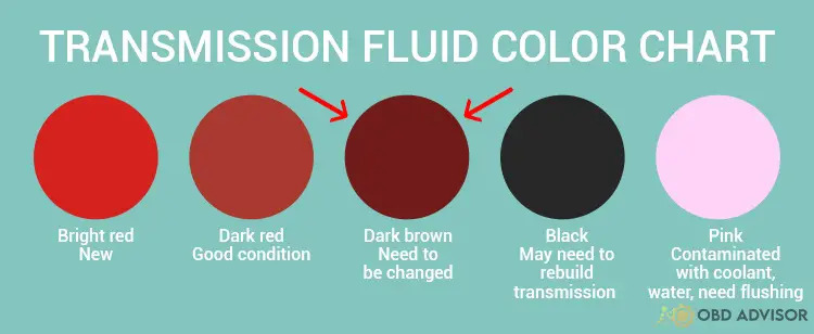
The Automatic Transmission Fluid (ATF) is filled in the torque converter. The torque converter and transmission are damaged if the fluid is contaminated, contains debris or sludge, or is old.
You need to check your transmission fluid to ensure whether the transmission fluid is the cause of this code or not.
Change the fluid right away if it’s dark brown.
Sometimes, P0741 combines with P0218 or P0729-P0736. In this particular case, the P0741 can be attached with P2757 (Lexus), P0740 and P2761 (BMW), and P1744 and P0218 (Ford) in your scanner to warn you to replace the transmission fluid.
Cause #7: Faulty Valve Body
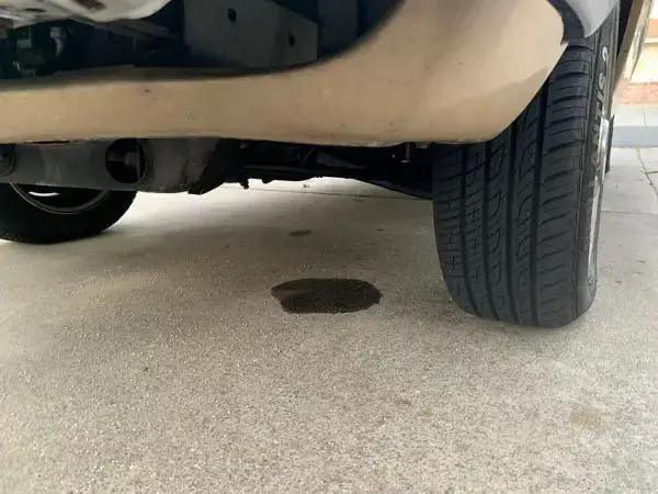
The valve body plays a vital role in the torque converter with various channels and passages in the automatic transmission. It interacts with the solenoid to push transmission fluid flow through those passages to initiate different clutches and switch gears.
The torque converter can not operate correctly when the valve body goes bad.
To know whether the valve body is good or not, there are a lot of signs for you to identify:
- P0741 appears alone or with P0700, and P0768.
- Incorrectly gear change.
- Harsh noise.
- Slipping whilst driving a manual box in the clutch.
- Transmission fluid leak.
Cause #8: Faulty Transmission Control Module (TCM)
The TCM measures severe signals from the engine speed sensor and the turbine speed sensor to estimate the torque converter slip value. Then, the TCM compares this value to the value preset in the TCM calibration.
P0741 pops up when this torque converter slip value exceeds 80 RPM. The slip value is inaccurate if the TCM fails, making TCC not work correctly.
This cause has a variety of signs to identify, including:
- P0741 combines with the P0700.
- Check engine light.
- Poor fuel mileage.
- Erratic shifting.
How Much Does It Cost To Fix The Code P0741?
The fixing cost of the P0741 is around $15 – $700 for DIY and $100 – $1000 for a mechanic shop or dealer.
However, it is based on the causes of your car and the area where you are at.
The estimated repair cost of the P0741
| Solutions | Cost |
|---|---|
| Replace torque converter | DIY: $150 – $500 Mechanic shop: $600 – $1000 |
| Replace the TCC solenoid / damaged wiring to TCC solenoid | DIY: $15 – $100 Mechanic shop: $100 – $400 |
| Repair damaged wiring to the transmission wiring harness | DIY: $50 – $250 Mechanic shop: $100 – $350 |
| Replace ECT sensor | DIY: $10 to $30 Mechanic shop: $85 to $170 |
| Change transmission fluid | DIY: $50 – $100 Mechanic shop: $80 – $250 |
| Replace the valve body | DIY: $250 – $500 Mechanic shop: $300 – $1000 |
| Replace the TCM | DIY: $450 – $700 Mechanic shop: $500 – $900 |
Note: The data in this table is collected in May 2022. The actual price depends on many factors, such as your car’s make and year, mechanic’s rate, time, market price, etc.
You Ask, I Answer
The P0741 error code isn’t a severe significant code, but you have to fix it right away to avoid the damage to the transmission.
I hope you can save your budget after reading my article.
If you have any other questions, don’t hesitate to leave a comment below, we’ll answer them all.
If you have had the same issue and fixed it before, share your story with us.
See ya!
Read more: The 9 Best OBD2 Scanners for 2024: The Only Review You Need
P0740: Torque Converter Clutch Circuit Malfunction
P1132 Ford Code: Ignition Issues Explored
P1132 Ford Code: Ignition Issues Explored
You’re behind the wheel of your dependable Ford, when all of a sudden, a warning light illuminates, signaling a potential problem. Connecting a scanner reveals a puzzling “P1132” code.
Fear not – it’s simply your car’s way of highlighting a hiccup in the engine’s performance. This article takes you on a concise journey to understand the P1132 Ford code, its causes, symptoms, and what steps you can take next.
Let’s dive in and decode the mystery together!
P1132 Ford: A Quick Overview
Check the overview of the P1132 Ford code below!
- Definition: Lack of HO2S11 (Upstream Heated Oxygen Sensor) Switch – Sensor Indicates Rich – Bank 1
- Severity: Medium
- DIY Skill Level: Intermediate
- Continue To Drive?: Yes
- Estimated Repair Cost: $50 – $300
What Does The P1132 Code Mean On Ford?
The trouble code P1132 is specific to Ford vehicles and indicates an issue with the upstream heated oxygen sensor. This sensor measures the oxygen levels within the exhaust fumes, which helps the car computer (ECM) regulate the air-fuel mixture for efficient combustion. The code is triggered when the ECM detects a lack of variation in the sensor’s voltage signal.
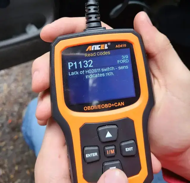
In simpler terms, the oxygen sensor’s job is to tell the ECM about the amount of oxygen in the exhaust. This information helps the computer ensure the engine runs smoothly and produces minimal emissions.
The P1132 code comes up if the sensor’s signal doesn’t change as expected, indicating a problem with the sensor or its communication with the car computer. This behavior might imply that the sensor is persistently reporting one level of oxygen (either rich or lean) or not functioning as intended. This issue can affect how well the engine runs and how efficiently it uses fuel.
Note:
- Please note that the upstream heated oxygen sensor refers to the sensor located before the catalytic converter.
- The P1132 Ford code can sometimes be accompanied by other related codes, like P0171, P0172, P1131 Ford, P1152 Ford, etc., especially if the issue is affecting multiple components of the vehicle’s emissions and fuel system. However, it’s not always guaranteed that additional codes will be present alongside P1132.
How Severe Is The P1132 Ford Code?
The P1132 Ford code can be classified as having a moderate severity level, which means that while immediate catastrophic failure might not be imminent, it’s important not to underestimate the potential impact on your vehicle’s performance, emissions, and safety.
In the short term, you might be able to continue driving with the code present, but it’s strongly recommended to address the issue as soon as possible. Neglecting a malfunctioning oxygen sensor can gradually lead to decreased engine efficiency, reduced fuel economy, and increased emissions. Over time, these effects could compound and potentially cause further complications.
What Are The Symptoms Of The P1132 Code On Ford Vehicles?
The P1132 Ford code is often associated with a range of symptoms that can provide clues to the underlying issue. While not all symptoms might be present in every case, here are some common signs that you might experience when this code is triggered:
- Check engine light
- Reduced fuel efficiency
- Bad engine performance
- Increased emissions
- Rough idling
- Potential for engine overheating
- Lack of power
Read more: P1131 Ford: Symptoms, Causes, and How to Fix
What Causes The P1132 Ford Code?
The P1132 Ford code can be caused by the following:
- Faulty oxygen sensor
- Wiring issues
- Vacuum leaks
- Fuel system problems
- Exhaust system leaks
- Engine mechanical problems
- Bad ECM (rarely)
How To Diagnose And Fix The P1132 Ford Code
Diagnosing and addressing the P1132 Ford code involves a structured approach to identify the root cause and apply the appropriate fixes. Here’s a step-by-step guide and the needed tools and parts for the fixing process:
Essential Tools And Parts
- Heated oxygen sensor
- Wiring connectors and harnesses
- Vacuum hoses
- Fuel injector(s)
- Fuel filter
- Mass Air Flow (MAF) sensor
- Exhaust Gas Recirculation (EGR) valve
- OBD-II scanner
- Multimeter
- Vacuum gauge
Step-by-step Procedure
Step 1: Inspect the oxygen sensor
- Visually inspect the wiring, connectors, and harnesses connected to the oxygen sensor.
- Look for any signs of damage, corrosion, or loose connections that might be affecting the sensor’s operation. Replace the sensor if necessary
Step 2: Check for vacuum leaks
- Inspect the vacuum hoses and connections for leaks, cracks, or disconnections by using a vacuum gauge.
- Fix any vacuum leaks to ensure accurate sensor readings.
Step 3: Test the oxygen sensor
- Test the oxygen sensor’s response using a multimeter or a specialized testing tool.
- Compare the readings to the specifications provided in your vehicle’s repair manual or you can consult this link.
Step 4: Verify exhaust system integrity
- Inspect the exhaust system for leaks before the oxygen sensor.
- Repair any leaks that could introduce oxygen into the exhaust stream.
Step 5: Check fuel system components
- Inspect the fuel system components, including the fuel injector(s) and fuel filter.
- Ensure they are functioning correctly and not affecting the air-fuel mixture.
Step 6: Examine engine mechanical components
- Test the Mass Air Flow (MAF) sensor and Exhaust Gas Recirculation (EGR) valve if applicable.
- Address any issues that could impact the air-fuel mixture.
Step 7: Check the ECM (if needed)
Consult with a dealership or qualified mechanic to check if your vehicle’s PCM or ECM requires a software update to resolve issues related to oxygen sensor monitoring.
Step 8: Clear codes and test drive
- After addressing any identified issues, clear the diagnostic trouble codes using the OBD-II scanner.
- Take your vehicle for a test drive to ensure that the code does not reappear and that the symptoms are resolved.
Read more: Complete List Of Ford OBD2 Codes for FREE Download
Estimated Costs For P1132 Code In Ford Vehicles
Estimating the cost to fix the P1132 Ford code can vary significantly based on factors such as the specific issue causing the code, your vehicle’s make and model and labor rates in your area.
Keep in mind that these are just rough estimates and the actual cost can differ. If you’re not confident in your DIY skills or want to ensure the issue is addressed correctly, it’s recommended to have a professional mechanic handle the diagnosis and repair.
While this might come with a higher upfront cost, it provides the peace of mind that the problem will be resolved accurately and that your vehicle’s performance and safety won’t be compromised.
Here’s a general breakdown:
| Repair Task | Estimated Cost Range |
| Oxygen Sensor Replacement | $50 – $200 |
| Wiring and Connector Repair | $50 – $200 |
| Vacuum Leak Repair | $50 – $150 |
| Other Component Replacement (fuel injectors, MAF sensors, or EGR valves) | $100 – $300 |
| ECM Replacement/Repair (rarely) | $200- $1000 |
P1132 Ford Infographic

Final Thoughts
Understanding the P1132 Ford code empowers car enthusiasts to navigate potential engine concerns with confidence. From its subtle symptoms to its implications on performance, this code highlights the need for timely attention.
Whether you’re a DIY mechanic or rely on professionals, addressing the code promptly ensures a smoother, more efficient journey.
If this article proved insightful, consider sharing it with fellow drivers and leaving your thoughts in the comments below. Safe travels!
Reference Sources
- FIXD. Oxygen Sensor: How it Works, Symptoms of a Bad One, & Replacement Cost.
- Newparts.com. Bank 1 Sensor 1: Upstream or Downstream?
P0462 Code: Fuel Level Sensor Troubles and How to Fix Them
P0462 Code: Fuel Level Sensor Troubles and How to Fix Them
When that check engine light suddenly appears on your dashboard and the P0462 code pops up on your scanner’s screen, your vehicle is sending a signal about a potential hiccup in its cooling system. In this article, we’re here to break down the meaning behind this code, highlight possible indicators, explain why it occurs, and provide step-by-step guidance to diagnose and resolve the issue.
Whether you’re a seasoned car enthusiast or simply curious about what’s happening beneath the hood, this article will simplify the process of dealing with the P0462 code.
Let’s dive in!
P0462 Code: A Quick Overview
Definition: Fuel Level Sensor ‘A’ Circuit Low
Severity: Medium
DIY Skill Level: Intermediate
Continue To Drive?: No
Estimated Repair Cost: $50 – $300
What Does the P0462 Code Mean?
The P0462 code is a message from your car’s computer system indicating a problem with the “Fuel Level Sensor ‘A’ Circuit Low.” In practical terms, the vehicle’s Powertrain Control Module (PCM) has detected an abnormal signal from the fuel level sensor (FLS). The FLS is responsible for measuring the fuel level inside the fuel tank. When the PCM receives an irrational or mismatched input signal from the FLS, it triggers the P0462 code.
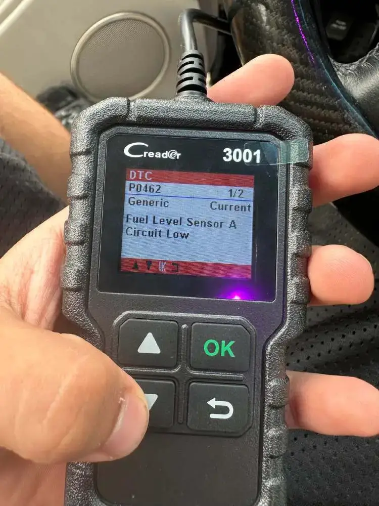
The P0462 is a generic trouble code. Therefore, it can show up in various models from manufacturers like Toyota, Ford, Chevrolet, Honda, and Nissan. When P0462 appears, it might come with related codes like P0460 (Fuel Level Sensor Circuit), and/or P0461 (Fuel Level Sensor Circuit Range/Performance). These codes offer more context, aiding mechanics in pinpointing the problem.
How Serious is the P0462 Code?
The P0462 code falls into the medium severity category. Continuing to drive with P0462 isn’t advisable. Inaccurate fuel readings can disrupt your travel plans and harm your vehicle.
Promptly addressing this issue ensures your fuel gauge remains reliable, preventing unexpected breakdowns and ensuring you can trust the information displayed. Consulting a mechanic for a thorough inspection and timely repair is the safest course of action, ensuring your journeys remain smooth and trouble-free.
What are the Symptoms of the P0462 Code?
When your P0462 is displayed on your vehicle, it may exhibit several symptoms indicating issues with the fuel level sensor circuit. Look out for:
- Illuminated Check Engine Light
- Inaccurate fuel gauge readings
- Fuel gauge stuck on empty, 1/2 or full
- Failed smog test
What are the Causes of the P0462 Code?
Several factors can trigger the P0462 code. Common causes include:
- Faulty fuel level sensor
- Damaged or corroded wiring in the fuel level sensor circuit
- Malfunctioning gauge cluster
- Damaged fuel tank
- Issues with the PCM
Read more: P0463 – Fuel Level Sensor “A” Circuit High
How To Diagnose and Repair P0462 Code?
In this section, we’ll guide you through the necessary steps to diagnose and fix the P0462 code in your vehicle, equipping you with the understanding and tools required to resolve this problem efficiently.
Diagnostic Tools and Essential Parts
- OBD-II scanner
- Multimeter
- Wiring diagram
- Replacement fuel level sensor
- Basic hand tools
- Instrument cluster
Step-by-Step Guide
- OBD-II Code Retrieval
Use an OBD-II scanner to retrieve the P0462 code and assess any accompanying codes. - Visual Inspection
Check for damaged wiring, loose connections, or corrosion in the fuel level sensor circuit. If it’s faulty, replace it.
- Sensor Testing
Use a multimeter to test the fuel level sensor’s resistance and voltage output. Consider replacing the sensor if necessary.
- Gauge Cluster Inspection
Inspect the gauge cluster for malfunctions affecting fuel readings. Repair or replace if it’s malfunctioning.
- PCM/ECM Testing (if needed):
Check the function of PCM and ensure it’s operating properly. Repair if any problems emerge. - Clearing the code:
Clear the codes with the OBD-II scanner and test the vehicle.
DIY Repair Level and Estimated Costs
This repair falls within the intermediate DIY level. While basic inspections can be done at home, replacing the fuel level sensor might require expertise. Costs vary based on parts and labor, approximately ranging from $150 to $300 for professional repair. If unsure, consult a mechanic for accurate diagnosis and safe repairs.
| Repair Task | Estimated Cost |
| Wiring and connector repair | $50 – $150 |
| Fuel Level Sensor | $50 – $150 |
| Instrument Cluster | $100 – $300 |
Conclusion
Dealing with the P0462 code in your car might seem overwhelming, but it’s manageable with the right information. By understanding the code, inspecting your vehicle, and addressing the issue, you can prevent inconvenient breakdowns. Remember, ignoring the problem can lead to more significant troubles. Taking on the challenge of the P0462 code is an opportunity to enhance your knowledge about your vehicle.
If you found this information helpful, share it with other car enthusiasts, regardless of their vehicle’s make and model. The P0462 code can affect any type of car. Safe travels!
Have you ever encountered the P0462 code, or do you possess additional insights or tips to contribute to the community? Feel free to drop a comment below. Your firsthand experiences and guidance can prove invaluable to others grappling with similar automotive dilemmas.
Reference Sources
Delphi Auto Parts, How to Test and Replace a Fuel Sending Unit. J.D. Power, What is a Smog Check?
P0102 – Mass Air Flow (MAF) Circuit Low Input
Your scan tool throws the P0102 code?
Here is a quick brief to let you know what you’re facing and what to expect.
- P0102 definition: Mass Air Flow (MAF) Circuit Low Input.
- Code type: Generic – P0102 indicates the same problem whether you’re having a Chevy, Ford, or Nissan, etc.
- Can I drive with the P0102 code? Yes, but extended driving can lead to costly repairs.
- Easy to fix? Beginner to intermediate DIY level.
- Cost: $30 to $380.
Keep driving with this code is not that dangerous. But the best way to avoid unnecessary expenses is to get it fixed ASAP.
Now let us take a deeper look into the code!
What Does The P0102 Code Mean?
The error P0102 code is triggered when the Mass Air Flow (MAF) sensor’s voltage is lower than 0.2v for a certain period of time. This number is telling the car’s computer that the amount of intake air is abnormally low.
How Does The MAF Sensor Work?
The MAF sensor measures how much air is coming into the combustion chamber. Using this data, the computer can determine how much fuel is needed.
A typical MAF sensor has a sensing wire. This wire heats up during operation and is further cooled by the airflow. The cooling initiates a decrease in resistance leading to an increase in voltage.
Therefore, the more air is coming, the higher the MAF’s output voltage. The number usually ranges from 0.5v to 5v.
What Happens When The MAF Sensor’s Output Voltage Is Lower Than 0.2v?
The MAF sensor’s voltage being lower than 0.2v is telling the computer that there is little to no air entering the engine.
Of course, the computer does not believe in this number as it knows it’s an irrational number.
So, what data does the computer take to adjust the air-fuel mixture?
The answer is O2 sensors!
The problem is that O2 sensors are located after where the combustion takes place. For that reason, there is a delay in the air-fuel ratio adjustment. As the result, your car can run just fine when cruising but it will hesitate when you suddenly accelerate.
Other codes related to the P0102 code are P0100 and P0101.
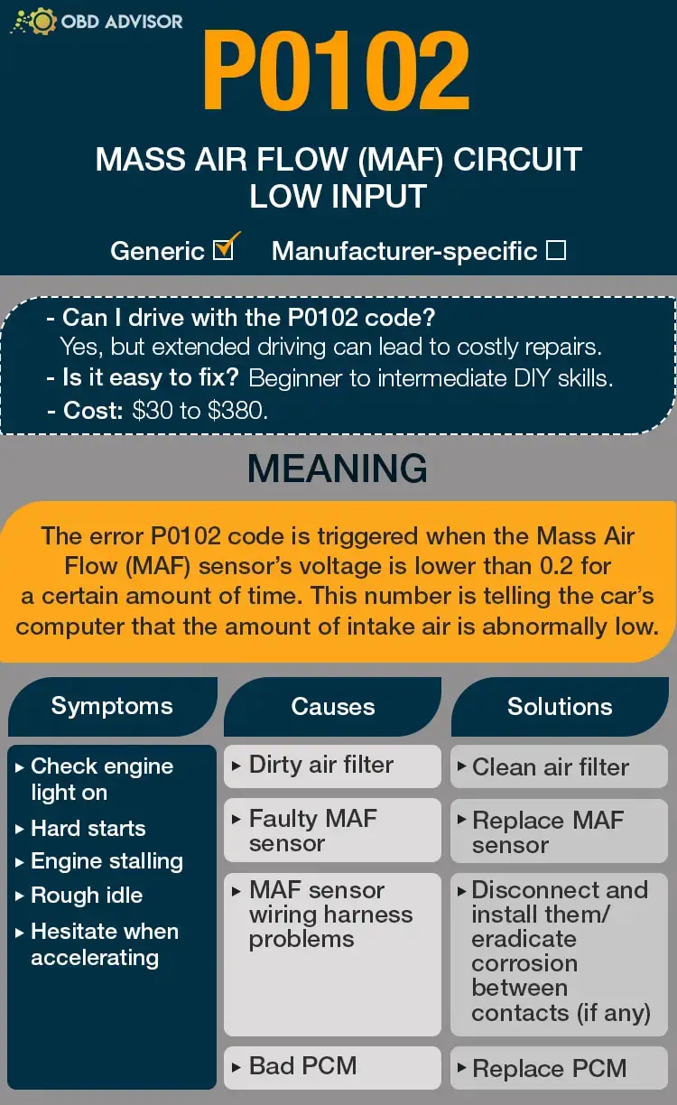
P0102: Causes, Symptoms, And How To Fix
Symptoms
Here are some common symptoms of P0102 that you should look out for:
- Check engine light on
- Hard starts
- Engine stalling
- Rough idle
- Hesitate when accelerating
Causes
Cause #1: Dirty Air Filter
The accumulation of dirt in your air filter will restrict airflow. Therefore, the MAF reports there is not enough air coming.
If this is your problem, your car can’t start (because there is actually no air for combustion.)
P0102 caused by a dirty air filter should be resolved by cleaning out the clogged air filter. This is an easy task and you can totally do it by yourself.
Cause #2: Faulty MAF Sensor
When the sensing wire inside the MAF gets dirty, airflow can not cool it down properly. This leads to the MAF’s voltage drop and it underreports the intake air mass.
The decision to replace your MAF sensor should be taken after a proper diagnosis.
Cause #3: MAF Sensor Wiring Harness Problems
Damaged MAF sensor wiring harness can contribute to your P0102 error code. The wiring could also be near components that consume higher voltage, such as alternators, ignition wires, etc. These could lead to false voltage readings as well.
Cause #4: PCM Issues (rare)
Finally, the Powertrain Control Module (PCM) will rarely be the source of your error code. A faulty PCM causes the vehicle to require multiple attempts before starting up. It may also result in the engine’s failure to start.
Replacing PCM should fix the problem. Installing this module will take about half an hour and require professional assistance to ensure proper operations.
P0102 Causes Identification: How to Diagnose
Following the recommended diagnostics process is the first step in resolving the P0102 code.
Diagnose Air Filter
First, open the hood and inspect the air filter to confirm if it is clogged or contaminated with debris. If it is the case, have your air filter cleaned with recommended cleaners.
Alternatively, when the air filter gets severely damaged, replacing it is the best option.
Diagnose MAF Sensor
After making sure that the air filter is clean, the MAF sensor is your next target.
The sensor is located between the air filter and the intake manifold. While the car is idling, unplug the MAF sensor, and the car should stall.
If it doesn’t, the MAF need to be cleaned or replaced.
Diagnose MAF Sensor Wiring Harness
Now, ensure you check the wiring of your MAF sensor thoroughly to inspect any broken, loose, frayed, or pinched cables and connections. Verify that the wiring harness is perfectly coupled to the MAF sensor.
Diagnose PCM
After eliminating all of the above possibilities, the last thing you should check is the PCM.
Up to this point, I recommend you have a mechanic inspect the PCM. This is a complicated and expensive process.
But don’t worry, this is a very rare case.
How Much Does It Cost To Fix The Code P0102?
Most of the time, replacing the MAF sensor will fix P0102. This is an easy fix and costs you about $30 to $150 to buy a new sensor.
The Estimated Repair Cost Of P0102
| Solutions | Repair Cost |
|---|---|
| Replace faulty MAF sensor | DIY: $30 to $150 Mechanic: $80 to $380 |
| Clean dirty air filter | DIY: a few bucks Mechanic: $15 to $85 |
| Replace PCM | DIY: not recommended Mechanic: $1,000 to $3,000 |
Note: The data in this table was collected in June 2022. The actual price depends on many factors, such as your car’s make and year, mechanic’s rate, etc.
You Ask, I Answer
The P0102 code is not as serious as you worry, but ignoring it could lead to further damages that cost an arm and a leg to repair.
Share your story with us if you have encountered the P0102 code and fixed it before.
Also, if you have any other questions related to this error code, feel free to leave a comment below, I’ll answer them all!
See ya!
Read more: The 9 Best OBD2 Scanners for 2024: The Only Review You Need
P1273 Nissan Code: A/F Issues And Lean Condition
P1273 Nissan Code: A/F Issues And Lean Condition
If you’re a Nissan vehicle owner who has encountered the P1273 error code, you’ve come to the right place. This code indicates specific air/fuel (A/F) issues and a lean condition within your vehicle’s system. This comprehensive guide will provide valuable insights into the meaning, severity, symptoms, causes, diagnosis, and repair of the P1273 Nissan code.
Whether you’re an experienced car enthusiast or a novice owner, we’ve got you covered. We’ll break down the technical aspects and equip you with practical knowledge to confidently address this issue. Read on!
P1273 Nissan Code: A Quick Summary
Take a quick look at the key information of the P1273 Nissan code!
- Definition: Air Fuel Sensor (Bank 1 Sensor 1) Circuit Lean Shift
- Severity: Medium
- DIY Skill Level: Intermediate
- Continue To Drive?: Yes
- Estimated Repair Cost: $100 – $400
What Does P1273 Nissan Code Mean
The P1273 error code on Nissan refers to a potential issue in the fuel system. When this code is triggered in your car, it indicates a lean running condition, specifically related to the operation of air-fuel ratio sensor 1 on bank 1.
In other words, the engine control module (ECM) has detected an imbalance in the air-fuel mixture, which can impact engine performance. To understand this code better, let’s explore the components involved and how they interact.
The air-fuel ratio sensor, also known as the A/F sensor, plays a crucial role in measuring the oxygen content in the exhaust gases. It provides feedback to the ECM to ensure the optimal air-fuel mixture (14.7:1 stoichiometric ratio) for combustion. In Bank 1, the ECM monitors the air-fuel ratio for any deviations from the expected values.

In certain conditions, such as during acceleration or deceleration, the ECM monitors lean-to-rich or rich-to-lean shifts. If the ECM detects a lean shift that persists beyond the specified parameters, it triggers the P1273 code.
It’s important to note that the P1273 code is commonly found in Nissan models such as Altima, Murano, Pathfinder, Sentra, Frontier, Quest, and 350Z. Altima, particularly the 2004 and 2005 models, is notorious for experiencing this code frequently.
Furthermore, there are other associated codes that may accompany P1273, including P1283, P0174, and various A/F sensor codes such as P0036, P0037, P0038, P0042, P0043, P0044, etc.
How Serious Is The P1273 Nissan Code?
The P1273 Nissan code is considered a medium-level severity. While it may not immediately cause a breakdown or severe damage to your vehicle, it should not be ignored. You can continue to drive with the code in the short term, but it is important to address it promptly.
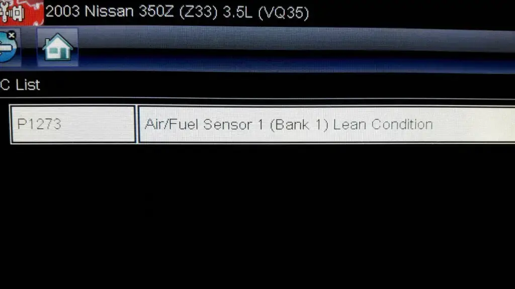
(Image credit: 350Z UK Forum)
Prolonged driving with the P1273 code may result in reduced fuel efficiency, decreased engine performance, and possible damage to the catalytic converter over time. Ignoring the code can also trigger additional related codes, complicating the diagnosis and repair process.
Read more: Nissan Trouble Codes: Comprehensive List For OBD1/OBD2
P1273 Nissan: Spotting the Telltale Signs
When encountering the P1273 Nissan error code, several symptoms may manifest:
- Service engine light illuminated
- Engine hard to start in cold conditions
- Fuel smell
- Mode $06 fault
- Engine starts up but won’t stay on and stalls
However, in some cases, the vehicle may drive well with no noticeable drivability symptoms.
Read more: Nissan Dashboard Warning Lights and Meanings (FULL list, FREE Download)
Root Causes Of P1273 Nissan Code
Some common culprits behind the P1273 code include:
- Poor connection or wiring issues related to the A/F sensor
- Open or short circuit conditions in the A/F sensor circuit
- Failed air-fuel ratio sensor (A/F sensor)
- Vacuum leaks in the intake system
- Issues with the fuel delivery system, such as a clogged fuel filter or weak fuel pump
- Defective MAF sensor
- Malfunctioning ECM (rarely)
Note:
Please remember that the above causes are general and commonly associated with the P1273 code in Nissan vehicles. However, it’s essential to remember that the underlying causes may vary in specific cases.
For instance, based on my experience, I’ve encountered situations where issues with coolant quality and leakage into the engine have been identified as contributing factors. The story from member Stealthm in this forum thread is an example.
Efficient Strategies For Resolving The P1273 Nissan Code
In this section, we will provide step-by-step instructions and a list of essential tools and parts needed to address the issue. By following this guide, you can effectively identify and resolve the C1130 code.
Essential Tools And Parts
To diagnose and repair the P1273 code in a Nissan, you will need the following tools and parts:
- OBD-II scanner or code reader
- Basic hand tools (such as wrenches and sockets)
- Multimeter
- Fuel pressure gauge
- MAF sensor cleaner
- Electrical tape and wire connectors
- A/F sensor
- Intake system components: gaskets, hoses, etc.
- Fuel delivery system components: fuel filter, fuel pump, etc.
- MAF sensor
- ECM
Step-by-Step Procedure
1. Retrieve DTCs
Connect an OBD-II scanner to your Nissan vehicle and retrieve all trouble codes, including P1273. Note any additional codes present. Prioritize addressing the codes directly impacting the air-fuel ratio sensor or related systems.
2. Inspect wiring related to A/F sensor
Inspect the engine bay for damaged or loose wiring related to the air-fuel ratio sensor. Check for disconnected or worn vacuum hoses.
3. Check for circuit issues
Examine the A/F sensor circuit for open or short circuits. Inspect wiring harnesses and connectors. Repair or replace damaged wires or connectors.
4. Test the air-fuel ratio sensor
Measure the sensor’s resistance and voltage output using a multimeter or diagnostic tool. Compare readings to specified values in the service manual. Replace the sensor if it fails the test.
5. Inspect the intake system
Check for vacuum leaks in the intake system. Inspect gaskets, hoses, and components. Repair or replace faulty parts.
6. Check fuel pressure
Measure fuel pressure on the fuel rail (aim for at least 55 psi). If pressure is low, check the fuel pressure regulator, fuel filter, and fuel pump for issues. Repair or replace as needed.
7. Check MAF sensor and intake plumbing
Inspect the MAF sensor for dirt or debris. Clean it if necessary using MAF sensor cleaner. Check clamps and connections between the MAF sensor and throttle body for leaks or looseness.
8. Inspect the ECM
If the previous steps don’t resolve the issue, inspect the engine control module (ECM). Ensure proper connections and check for loose or damaged wires. Consult a professional if ECM malfunction is suspected.
Note:
- Follow the manufacturer’s instructions and any additional notes or tips in the service manual for your vehicle model.
- The A/F sensor location may vary depending on the specific Nissan model and engine type. To find the precise location of the A/F sensor in Nissan, refer to the vehicle’s manual or visit reliable online sources such as this diagram for A/F sensor location in Nissan Altima.
DIY Repair Level And Estimated Costs
The DIY repair level for diagnosing and fixing the P1273 code in a Nissan is moderate. It requires basic mechanical knowledge and the ability to use diagnostic tools and perform sensor replacement.
The estimated cost for this repair task may vary depending on factors such as the brand and quality of the A/F sensor, labor rates in your area, and whether you choose to do the repair yourself or seek assistance from a professional mechanic.
Here is a table listing the estimated costs for the main repair tasks:
| Repair Task | Estimated Cost Range |
| Diagnostic | $50 – $150 |
| Wiring repair | $50 – $200 |
| A/F sensor repair/replacement | $200 – $400 |
| Intake system components repair/replacement | $100 – $300 |
| Fuel delivery system components repair/replacement | $100 – $300 |
| MAF sensor repair/replacement | $100 – $300 |
| ECM repair/replacement | $200 – $1000 |
P1273 Nissan Infographic
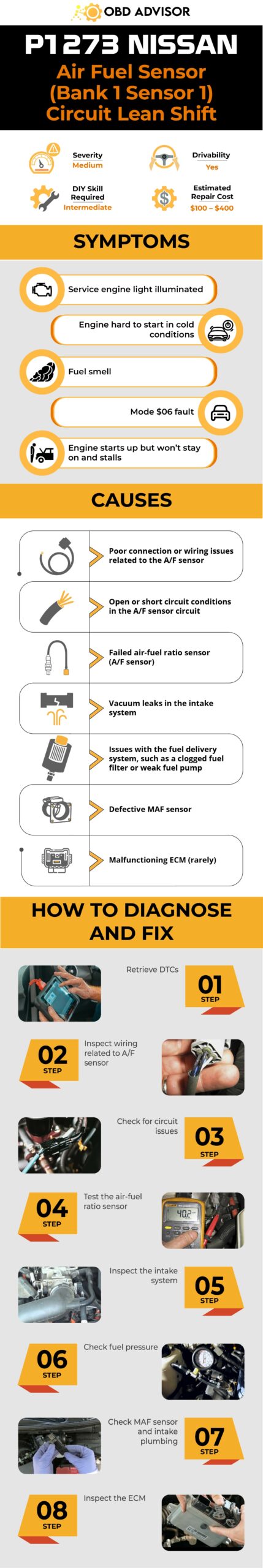
Final Thoughts
In conclusion, understanding and addressing the P1273 code in Nissan vehicles can help ensure optimal engine performance and fuel efficiency. By following the general diagnostic and repair steps outlined, you can effectively troubleshoot and resolve issues related to the Air/Fuel Ratio (A/F) sensor or its circuit.
If you found this information helpful, share it with others who may benefit from it. Additionally, we would love to hear from you if you have any comments, questions, or personal experiences related to the P1273 code.
For information on other OBD2 codes and to troubleshoot specific issues with your vehicle, visit our OBD code lookup tool.
Safe travels and happy diagnosing!
Reference Sources
- Nissan Help Forum, P1273 – Nissan.
- My350z Forum, What does code P1273 mean?.
- YourMechanic, After oxygen sensor replacement I’m getting a P1273 error…
- Reddit, Question about code P1273 and P0174.
P0463 – Fuel Level Sensor “A” Circuit High
P0463 – Fuel Level Sensor “A” Circuit High
P0463 Code Definition
What Does P0463 Mean?
What Are The Symptoms Of The P0463 Code?
What Are The Causes Of P0463?
How Serious Is The P0463 Code?
How To Diagnose And Fix The P0463 Code
Tools You’ll Need:
Method:
Common Mistakes To Avoid While Diagnosing The P0463 Code
P1564 Nissan Code: How To Get Your Cruise Control Back On Track
P1564 Nissan Code: How To Get Your Cruise Control Back On Track
Imagine you’re driving your Nissan when suddenly the “Check Engine” light comes on. You decide to plug an OBD2 scanner in to know where the problem is, and you then discover that the culprit behind the warning is the P1564 Nissan code, linked specifically to the Advanced Speed Control Device (ASCD) steering switch.
In this article, we’ll focus on the P1564 code and explain it in simple terms. By the end, you’ll better understand the issue and what you can do to keep your car running smoothly. So, let’s dive in and unlock the mystery of the P1564 Nissan code!
P1564 Nissan: A Quick Overview
Below is a summary of the P1564 Nissan code. Check it out.
- Definition: ASCD Steering Switch Circuit Malfunction
- How Serious Is It?: Medium
- DIY Skill Level: Intermediate
- Continue To Drive?: Yes
- Estimated Repair Cost: $20 – $1500
What Does The P1564 Nissan Code Mean?
P1564 is a diagnostic trouble code (DTC) that pertains to Nissan’s ASCD system. This code is triggered when the Engine Control Module (ECM) detects irregularities in the ASCD steering switch’s electrical signals. This occurs when an excessively high voltage signal is sent from the ASCD steering switch to the ECM, the input signal from the switch is out of the specified range, or the switch is stuck in the ON position.
Let’s learn about the ASCD system. The ASCD steering switch consists of multiple buttons, each associated with specific cruise control functions like setting the desired speed, resuming previous speed, or canceling the system. The switch’s buttons have unique electrical resistance values, and when a button is pressed, the ECM reads the corresponding voltage variations to determine the intended function. So when the voltage is abnormal in the ASCD’s electrical signal, the P1564 is set.
(Credit: usa.nissannews.com)
How Serious Is The P1564 Nissan Code?
The P1564 Nissan code indicates a moderate level of severity. While it may not immediately impact drivability, it should not be ignored. If the ASCD steering switch malfunctions, the cruise control system may become inoperative, affecting driving comfort on long trips. In such cases, you can continue to drive the vehicle with caution. However, it’s essential to have the issue diagnosed and repaired promptly to restore the system’s functionality.
Read more: P1614 Nissan Code: Causes and Solutions of NATS Issues
What Are The Symptoms?
There are some symptoms if P1260 is set on your Ford:
- Malfunction Indicator Lamp (MIL) illuminated
- Loss of cruise control capabilities
What Are The Potential Causes?
Causes of the P1564 Nissan code may include:
- Damaged wiring and connectors
- Bad ASCD steering switch
- Faulty ECM
How To Diagnose And Fix the P1564 Nissan Code?
Dealing with the P1564 Nissan code related to the ASCD steering switch can seem daunting, but you can resolve it step by step. Here’s a simple guide to help you fix the issue:
Essential Tools And Parts
- Diagnostic scanner
- ASCD switch assembly
- Multimeter
- Basic tools (screwdrivers, pliers, etc.)
Fixing Nissan P1564: Step-by-step Procedure
Step 1: Visual Inspection
Carefully examine the ASCD steering switch, like cancel sw, cruise lamp sw, or resume/acc sw, etc., and its wiring for any visible damage, loose connections, or signs of wear. Look for frayed wires, corroded connectors, or any other obvious issues that could affect the switch’s functionality.
Step 2: Check Electrical Resistance
Use a multimeter set to the resistance (ohms) setting. Measure the electrical resistance of each button on the ASCD steering switch. Compare the readings you get with the manufacturer’s specifications for each button. Significant deviations from the expected values could indicate a faulty switch.
Step 3: Test Voltage Signals
Set the multimeter to the voltage setting. Here are the expected voltage values you should get when you measure the G/Y wire at the ASCD steering switch with the ignition switch turned ‘ON’:
- When the ASCD steering switch is “OFF”, you should see around 4.0V.
- If the CRUISE switch is “ON”, the voltage should be approximately 0V.
- For the CANCEL switch being “ON”, the voltage should be around 1V.
- When the COAST/SET switch is “ON”, the voltage should be roughly 2V.
- Finally, if the ACCEL/RES switch is “ON”, you should read around 3V.
Step 4: Repair Or Replace
If all the values match the specifications above, then the switch is likely the problem. However, if any of the values are not within the expected ranges, the wiring might have an issue. It’s vital to get the wiring issues addressed in this case.
Step 5: Clear Codes
Using the diagnostic scanner, clear the P1564 code from the ECM. This step is essential after making repairs or replacements. Clearing the code will reset the system and allow you to check if the issue has been resolved.
Step 6: Functional Test
Take your vehicle for a test drive in a safe area. Engage the cruise control functions associated with the ASCD steering switch. Monitor the system’s performance and watch for any warning lights. Make sure the cruise control operates smoothly without any unexpected behavior.
Estimated Cost For Fixing P1564 On Nissan Vehicles
Safety should be a priority when dealing with vehicle repairs. If you find that the necessary skills and expertise required for these repairs are beyond your DIY abilities, it’s strongly recommended to seek assistance from a qualified mechanic. They have the experience and knowledge to ensure the repairs are done correctly and safely.
Below is a rough estimated cost breakdown for the mentioned repairs. Please keep in mind that these are approximate figures and actual costs can vary depending on various factors.
| Repair Task | Estimated Cost |
| Wiring and Connectors Repair | $50 to $200 |
| ASCD Steering Switch Replacement | $100 to $200 |
| ECM Replacement | $500 to $1500 |
P1564 Nissan Infographic
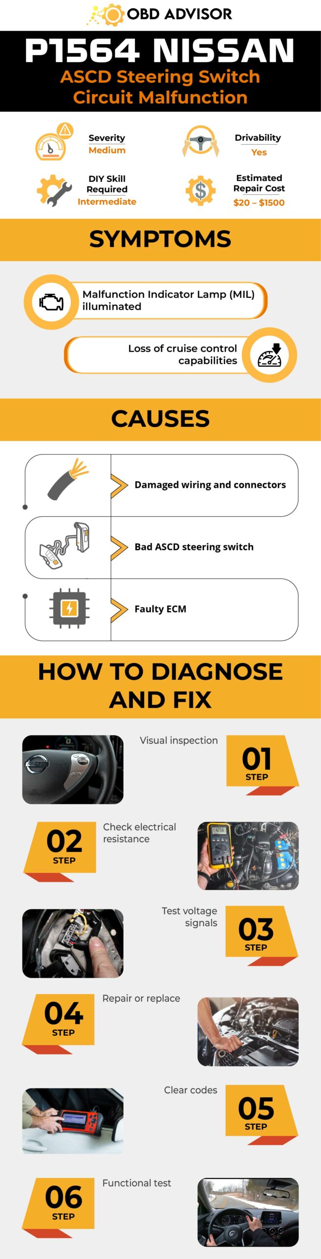
Conclusion
In conclusion, comprehending the P1564 Nissan code is crucial. Understanding the code’s implications empowers drivers to make informed decisions about their vehicle’s health. Whether you DIY or get pro help, grasping the code’s meaning means better car care. Decoding and tackling the P1564 code gets your car back on track and shows you’re a driver in the know, taking care of your ride.
If you found this article helpful in demystifying the P1564 Nissan code and grasping the ASCD steering switch, share it with others facing similar challenges. Have questions, insights, or experiences to share? Drop them in the comments below. Let’s start a discussion that enriches our driving journeys!
References Sources
- Nissan_Pathfinder_LE_P1564, PRODEMAND
- Nissan Altima 2007-2012 Service Manual: Automatic speed control device (ASCD), Nissan Altima
GM OBD2 Codes List For FREE Download [Generic + Manufacturer-specific]
GM OBD2 Codes List For FREE Download [Generic + Manufacturer-specific]
Are you the proud owner of a GM car, such as a Chevrolet, Buick, GMC, or Cadillac? Have you ever wondered what those mysterious “Check Engine” lights mean and how to troubleshoot them effectively?
Look no further!
With this post, we’ll provide you with a comprehensive list of GM OBD2 codes, empowering you to decode these mysterious signals and gain insights into the health of your vehicle.
So, if you’re an avid GM enthusiast or a curious owner seeking to enhance your knowledge of your beloved vehicles, this OBD2 codes list post is tailor-made for you.
Let’s dive in!
GM OBD2 Codes List and Meaning [FULL]
Free Download: Full GM OBD2 Trouble Codes List and Meaning PDF
This list applies to GM’s cars, including Chevy, Cadillac, Buick, and GMC. Moreover, we divide it into four parts: Powertrain, Network, Body, and Chassis, which helps you quickly find the codes you need for engine, network, body control, and chassis issues.
Note: Use the search box in the table below to quickly find the specific code you’re looking for.
Powertrain (P) Codes List
| Code | Definition |
|---|---|
| P0001 | Fuel Volume Reg Ctrl Circ/Open |
| P0002 | Fuel Volume Reg Ctrl Circ Range/Perf |
| P0003 | Fuel Volume Reg Ctrl Circ Low |
| P0004 | Fuel Volume Reg Ctrl Circ High |
| P0005 | Fuel Shutoff Valve A Ctrl Circ/Open |
| P0006 | Fuel Shutoff Valve A Ctrl Circ Low |
| P0007 | Fuel Shutoff Valve A Ctrl Circ High |
| P0008 | Engine Pos Sys Perf Bank1 |
| P0009 | Engine Pos Sys Perf Bank2 |
| P0010 | A Camshaft Pos Actuator Circ (bank |
| P0011 | A Camshaft Pos TimingOverAdvanced (bank |
| P0012 | A Camshaft Pos TimingOverRetarded (bank |
| P0013 | B Camshaft Pos Actuator Circ (bank |
| P0014 | B Camshaft Pos TimingOverAdvanced (bank |
| P0015 | B Camshaft Pos TimingOverRetarded (bank |
| P0016 | Crank PosCamshaft Pos Correlation Bank1 SensorA |
| P0017 | Crank PosCamshaft Pos Correlation Bank1 SensorB |
| P0018 | Crank PosCamshaft Pos Correlation Bank2 SensorA |
| P0019 | Crank PosCamshaft Pos Correlation Bank2 SensorB |
| P0020 | A Camshaft Pos Actuator Circ (bank2) |
| P0021 | A Camshaft Pos TimingOverAdvanced (bank2) |
| P0022 | A Camshaft Pos TimingOverRetarded (bank2) |
| P0023 | B Camshaft Pos Actuator Circ (bank2) |
| P0024 | B Camshaft Pos TimingOverAdvanced (bank2) |
| P0025 | B Camshaft Pos TimingOverRetarded (bank2) |
| P0026 | Intake Valve Ctrl Solenoid Circ Range/Perf Bank1 |
| P0027 | Exhaust Valve Ctrl Solenoid Circ Range/Perf Bank1 |
| P0028 | Intake Valve Ctrl Solenoid Circ Range/Perf Bank2 |
| P0029 | Exhaust Valve Ctrl Solenoid Circ Range/Perf Bank2 |
| P0030 | HO2S Heater Ctrl Circ (bank1, Sensor) |
| P0031 | HO2S Heater Ctrl Circ Lo (bank1, Sensor) |
| P0032 | HO2S Heater Ctrl Circ Hi (bank1, Sensor) |
| P0033 | Turbo Charger Bypass Valve Ctrl Circ |
| P0034 | Turbo Charger Bypass Valve Ctrl Circ Lo |
| P0035 | Turbo Charger Bypass Valve Ctrl Circ Hi |
| P0036 | HO2S Heater Ctrl Circ (bank1, Sensor2) |
| P0037 | HO2S Heater Ctrl Circ Lo (bank1, Sensor2) |
| P0038 | HO2S Heater Ctrl Circ Hi (bank1, Sensor2) |
| P0039 | T/S Charger Bypass Valve Ctrl Circ Range/Perf |
| P0040 | O2 Sensor Signals Swapped Bank1 Sensor 1/ Bank2 Sensor 1 |
| P0041 | O2 Sensor Signals Swapped Bank1 Sensor 2/ Bank2 Sensor 2 |
| P0042 | HO2S Heater Ctrl Circ (bank1, Sensor 3) |
| P0043 | HO2S Heater Ctrl Circ Lo (bank1, Sensor 3) |
| P0044 | HO2S Heater Ctrl Circ Hi (bank1, Sensor 3) |
| P0045 | T/S Charger Boost Ctrl Solenoid Circ/Open |
| P0046 | T/S Charger Boost Ctrl Solenoid Circ Range/Perf |
| P0047 | T/S Charger Boost Ctrl Solenoid Circ Low |
| P0048 | T/S Charger Boost Ctrl Solenoid Circ High |
| P0049 | T/S Charger Turbine Overspeed |
| P0050 | HO2S Heater Ctrl Circ (bank2, Sensor |
| P0051 | HO2S Heater Ctrl Circ Lo (bank2, Sensor |
| P0052 | HO2S Heater Ctrl Circ Hi (bank2, Sensor |
| P0053 | HO2S Heater Resistance Bank1 Sensor 1 |
| P0054 | HO2S Heater Resistance Bank1 Sensor 2 |
| P0055 | HO2S Heater Resistance Bank1 Sensor 3 |
| P0056 | HO2S Heater Ctrl Circ (bank2, Sensor2) |
| P0057 | HO2S Heater Ctrl Circ Lo (bank2, Sensor2) |
| P0058 | HO2S Heater Ctrl Circ Hi (bank2, Sensor2) |
| P0059 | HO2S Heater Resistance Bank2 Sensor 1 |
| P0060 | HO2S Heater Resistance Bank2 Sensor 2 |
| P0061 | HO2S Heater Resistance Bank2 Sensor 3 |
| P0062 | HO2S Heater Ctrl Circ (bank2, Sensor 3) |
| P0063 | HO2S Heater Ctrl Circ Lo (bank2, Sensor 3) |
| P0064 | HO2S Heater Ctrl Circ Hi (bank2, Sensor 3) |
| P0065 | Air Assisted Injector Ctrl Range/Perf |
| P0066 | Air Assisted Injector Ctrl Circ/Circ Lo |
| P0067 | Air Assisted Injector Ctrl Circ Hi |
| P0068 | MAP/MAFThrottle Pos Correlation |
| P0069 | MAPBarometric Press Correlation |
| P0070 | Ambient Air Temp Sensor Circ |
| P0071 | Ambient Air Temp Sensor Range/Perf |
| P0072 | Ambient Air Temp Sensor Circ Lo Input |
| P0073 | Ambient Air Temp Sensor Circ Hi Input |
| P0074 | Ambient Air Temp Sensor Circ Interm |
| P0075 | Intake Valve Ctrl Circ (bank |
| P0076 | Intake Valve Ctrl Circ Lo (bank |
| P0077 | Intake Valve Ctrl Circ Hi (bank |
| P0078 | Exhaust Valve Ctrl Circ (bank |
| P0079 | Exhaust Valve Ctrl Circ Lo (bank |
| P0080 | Exhaust Valve Ctrl Circ Hi (bank |
| P0081 | Intake Valve Ctrl Circ (bank2) |
| P0082 | Intake Valve Ctrl Circ Lo (bank2) |
| P0083 | Intake Valve Ctrl Circ Hi (bank2) |
| P0084 | Exhaust Valve Ctrl Circ (bank2) |
| P0085 | Exhaust Valve Ctrl Circ Lo (bank2) |
| P0086 | Exhaust Valve Ctrl Circ Hi (bank2) |
| P0087 | Fuel Rail/Sys PresToo Lo |
| P0088 | Fuel Rail/Sys PresToo Hi |
| P0089 | Fuel Pres Reg Perf |
| P0090 | Fuel Pres Reg Ctrl Circ |
| P0091 | Fuel Pres Reg Ctrl Circ Lo |
| P0092 | Fuel Pres Reg Ctrl Circ Hi |
| P0093 | Fuel Sys Leak DetectedLarge Leak |
| P0094 | Fuel Sys Leak DetectedSmall Leak |
| P0095 | Intake Air Temp Sensor 2 Circ |
| P0096 | Intake Air Temp Sensor 2 Circ Range/Perf |
| P0097 | Intake Air Temp Sensor 2 Circ Low |
| P0098 | Intake Air Temp Sensor 2 Circ High |
| P0099 | Intake Air Temp Sensor 2 Circ Interm/Erratic |
| P0100 | Mass/Volume Air Flow Circ Error |
| P0101 | Mass/Volume Air Flow Circ Range/Perf |
| P0102 | Mass/Volume Air Flow Circ Lo Input |
| P0103 | Mass/Volume Air Flow Circ Hi Input |
| P0104 | Mass/Volume Air Flow Circ Interm |
| P0105 | MAP/Baro Pres Circ Error |
| P0106 | MAP/Baro Pres Circ Range/Perf |
| P0107 | MAP/Baro Pres Circ Lo Input |
| P0108 | MAP/Baro Pres Circ Hi Input |
| P0109 | MAP/Baro Pres Circ Interm |
| P0110 | Intake Air Temp Circ Error |
| P0111 | Intake Air Temp Circ Range/Perf |
| P0112 | Intake Air Temp Circ Lo Input |
| P0113 | Intake Air Temp Circ Hi Input |
| P0114 | Intake Air Temp Circ Interm |
| P0115 | Eng Coolant Temp Circ Error |
| P0116 | Eng Coolant Temp Circ Range/Perf |
| P0117 | Eng Coolant Temp Circ Lo Input |
| P0118 | Eng Coolant Temp Hi Input |
| P0119 | Eng Coolant Temp Interm |
| P0120 | Throttle Pos Sensor/Switch A Circ Error |
| P0121 | Throttle Pos Sensor/Switch A Circ Range/Perf |
| P0122 | Throttle Pos Sensor/Switch A Circ Lo Input |
| P0123 | Throttle Pos Sensor/Switch A Circ Hi Input |
| P0124 | Throttle Pos Sensor/Switch A Circ Interm |
| P0125 | Insuff Coolant Temp for Closed Loop Fuel Ctrl |
| P0126 | Insuff Coolant Temp Stable Operation |
| P0127 | Intake Air Temp Too Hi |
| P0128 | Coolant Temp below Thermostat |
| P0129 | Barometric Press Too Low |
| P0130 | Oxy Sensor Circ (bank1, Sensor |
| P0131 | Oxy Sensor Circ Lo Voltage (bank1, Sensor |
| P0132 | Oxy Sensor Circ Hi Voltage (bank1, Sensor |
| P0133 | Oxy Sensor Circ Slow Response (bank1, Sens |
| P0134 | Oxy Sens Circ No Activity Detected (bank1 Sens |
| P0135 | Oxy Sensor Heater Circ (bank1, Sensor |
| P0136 | Oxy Sensor Circ (bank1, Sensor2) |
| P0137 | Oxy Sensor Circ Lo Voltage (bank1, Sensor2) |
| P0138 | Oxy Sensor Circ Hi Voltage (bank1, Sensor2) |
| P0139 | Oxy Sensor Circ Slow Response (bank1, Sensor2) |
| P0140 | Oxy Sens Circ No Activity Detected (bank1Sens2) |
| P0141 | Oxy Sensor Heater Circ (bank1, Sensor2) |
| P0142 | Oxy Sensor Circ (bank1, Sensor 3) |
| P0143 | Oxy Sensor Circ Lo Voltage (bank1, Sensor 3) |
| P0144 | Oxy Sensor Circ Hi Voltage (bank1, Sensor 3) |
| P0145 | Oxy Sensor Circ Slow Response (bank1, Sensor 3) |
| P0146 | Oxy Sensor Circ No Activity Detected (bank1 Sens3) |
| P0147 | Oxy Sensor Heater Circ (bank1, Sensor 3) |
| P0148 | Fuel Delivery Error |
| P0149 | Fuel Timing Error |
| P0150 | Oxy Sensor Circ (bank2, Sensor |
| P0151 | Oxy Sensor Circ Lo Voltage (bank2, Sensor |
| P0152 | Oxy Sensor Circ Hi Voltage (bank2, Sensor |
| P0153 | Oxy Sensor Circ Slow Response (bank2, Sensor |
| P0154 | Oxy Sensor Circ No Activity Detected (bank2 Sens |
| P0155 | Heated Oxy Sensor Heater Circ (bank2, Sensor |
| P0156 | Oxy Sensor Circ (bank2, Sensor2) |
| P0157 | Oxy Sensor Circ Lo Voltage (bank2, Sensor2) |
| P0158 | Oxy Sensor Circ Hi Voltage (bank2, Sensor2) |
| P0159 | Oxy Sensor Circ Slow Response (bank2, Sensor2) |
| P0160 | Oxy Sensor Circ No Activity Detected (bank2 Sens2) |
| P0161 | Heated Oxy Sensor Heater Circ (bank2, Sensor2) |
| P0162 | Oxy Sensor Circ (bank2, Sensor 3) |
| P0163 | Oxy Sensor Circ Lo Voltage (bank2, Sensor 3) |
| P0164 | Oxy Sensor Circ Hi Voltage (bank2, Sensor 3) |
| P0165 | Oxy Sensor Circ Slow Response (bank2, Sensor 3) |
| P0166 | Oxy Sensor Circ No Activity Detected (bank2 Sens3) |
| P0167 | Heated Oxy Sensor Heater Circ (bank2, Sensor 3) |
| P0168 | Eng Fuel Temp Hi |
| P0169 | Incorrect Fuel ComPos |
| P0170 | Fuel Trim Error (bank |
| P0171 | Sys too Lean (bank |
| P0172 | Sys too Rich (bank |
| P0173 | Fuel Trim Error (bank2) |
| P0174 | Sys too Lean (bank2) |
| P0175 | Sys too Rich (bank2) |
| P0176 | Fuel ComPos Sensor Circ Error |
| P0177 | Fuel ComPos Sensor Circ Range/Perf |
| P0178 | Fuel ComPos Sensor Circ Lo Input |
| P0179 | Fuel ComPos Sensor Circ Hi Input |
| P0180 | Fuel Temp SensorA Circ Error |
| P0181 | Fuel Temp SensorA Circ Range/Perf |
| P0182 | Fuel Temp SensorA Circ Lo Input |
| P0183 | Fuel Temp SensorA Circ Hi Input |
| P0184 | Fuel Temp SensorA Circ Interm |
| P0185 | Fuel Temp SensorB Circ Error |
| P0186 | Fuel Temp SensorB Circ Range/Perf |
| P0187 | Fuel Temp SensorB Circ Lo Input |
| P0188 | Fuel Temp SensorB Circ Hi Input |
| P0189 | Fuel Temp SensorB Circ Interm |
| P0190 | Fuel Rail Pres Sensor Circ Error |
| P0191 | Fuel Rail Pres Sensor Circ Range/Perf |
| P0192 | Fuel Rail Pres Sensor Circ Lo Input |
| P0193 | Fuel Rail Pres Sensor Circ Hi Input |
| P0194 | Fuel Rail Pres Sensor Circ Interm |
| P0195 | Eng Oil Temp Sensor Error |
| P0196 | Eng Oil Temp Sensor Range/Perf |
| P0197 | Eng Oil Temp Sensor Circ Lo Input |
| P0198 | Eng Oil Temp Sensor Circ Hi Input |
| P0199 | Eng Oil Temp Sensor Interm |
| P0200 | Injector Circ Error |
| P0201 | Injector Circ ErrorCyl1 |
| P0202 | Injector Circ ErrorCyl2 |
| P0203 | Injector Circ ErrorCyl3 |
| P0204 | Injector Circ ErrorCyl4 |
| P0205 | Injector Circ ErrorCyl5 |
| P0206 | Injector Circ ErrorCyl6 |
| P0207 | Injector Circ ErrorCyl7 |
| P0208 | Injector Circ ErrorCyl8 |
| P0209 | Injector Circ ErrorCyl9 |
| P0210 | Injector Circ ErrorCyl10 |
| P0211 | Injector Circ ErrorCyl11 |
| P0212 | Injector Circ ErrorCyl12 |
| P0213 | Cold Start Injector 1 Error |
| P0214 | Cold Start Injector 2 Error |
| P0215 | Eng Shutoff Solenoid Error |
| P0216 | Inj Timing Ctrl Circ Error |
| P0217 | Eng Over temp Condition |
| P0218 | Tran Over temp Condition |
| P0219 | Throttle Sw B Circ Error/Eng Over speed Condition |
| P0220 | Throttle Pos Sensor/Switch B Circ Error |
| P0221 | Throttle Pos Sensor/Switch B Circ Range/Perf |
| P0222 | Throttle Pos Sensor/Switch B Circ Lo Input |
| P0223 | Throttle Pos Sensor/Switch B Circ Hi Input |
| P0224 | Throttle Pos Sensor/Switch B Circ Interm |
| P0225 | Throttle Pos Sensor/Switch C Circ Error |
| P0226 | Throttle Pos Sensor/Switch C Circ Range/Perf |
| P0227 | Throttle Pos Sensor/Switch C Circ Lo Input |
| P0228 | Throttle Pos Sensor/Switch C Circ Hi Input |
| P0229 | Throttle Pos Sensor/Switch C Circ Interm |
| P0230 | Fuel Pump Relay Dvr Fail |
| P0231 | Fuel Pump Relay Dvr Circ Fail On |
| P0232 | Fuel Pump Relay Dvr Circ Fail Off |
| P0233 | Fuel Pump Relay Dvr Interm |
| P0234 | Eng Over boost Condition |
| P0235 | Turbo Boost SensorA Circ Error |
| P0236 | Turbo Boost SensorA Circ Perf |
| P0237 | Turbo Boost SensorA Circ Lo Input |
| P0238 | Turbo Boost SensorA Circ Hi Input |
| P0239 | Turbo Boost SensorB Circ Error |
| P0240 | Turbo Boost SensorB Circ Perf |
| P0241 | Turbo Boost SensorB Circ Lo Input |
| P0242 | Turbo Boost SensorB Circ Hi Input |
| P0243 | Turbo Wastegate Solenoid A Error |
| P0244 | Turbo Wastegate Solenoid A Range/Perf |
| P0245 | Turbo Wastegate Solenoid A Lo |
| P0246 | Turbo Wastegate Solenoid A Hi |
| P0247 | Turbo Wastegate Solenoid A Error |
| P0248 | Turbo Wastegate Solenoid A Range/Perf |
| P0249 | Turbo Wastegate Solenoid A Lo |
| P0250 | Turbo Wastegate Solenoid A Hi |
| P0251 | Inj Pump Fuel Metering Ctrl A Error |
| P0252 | Inj Pump Fuel Metering Ctrl A Range/Perf |
| P0253 | Inj Pump Fuel Metering Ctrl A Lo |
| P0254 | Inj Pump Fuel Metering Ctrl A Hi |
| P0255 | Inj Pump Fuel Metering Ctrl A Interm |
| P0256 | Inj Pump Fuel Metering Ctrl A Error |
| P0257 | Inj Pump Fuel Metering Ctrl A Range/Perf |
| P0258 | Inj Pump Fuel Metering Ctrl A Lo |
| P0259 | Inj Pump Fuel Metering Ctrl A Hi |
| P0260 | Inj Pump Fuel Metering Ctrl A Interm |
| P0261 | Injector Circ LoCyl1 |
| P0262 | Injector Circ HiCyl1 |
| P0263 | Cyl1 Contribution/Balance Fault |
| P0264 | Injector Circ LoCyl2 |
| P0265 | Injector Circ HiCyl2 |
| P0266 | Cyl2 Contribution/Balance Fault |
| P0267 | Injector Circ LoCyl3 |
| P0268 | Injector Circ HiCyl3 |
| P0269 | Cyl3 Contribution/Balance Fault |
| P0270 | Injector Circ LoCyl4 |
| P0271 | Injector Circ HiCyl4 |
| P0272 | Cyl4 Contribution/Balance Fault |
| P0273 | Injector Circ LoCyl5 |
| P0274 | Injector Circ HiCyl5 |
| P0275 | Cyl5 Contribution/Balance Fault |
| P0276 | Injector Circ LoCyl6 |
| P0277 | Injector Circ HiCyl6 |
| P0278 | Cyl6 Contribution/Balance Fault |
| P0279 | Injector Circ LoCyl7 |
| P0280 | Injector Circ HiCyl7 |
| P0281 | Cyl7 Contribution/Balance Fault |
| P0282 | Injector Circ LoCyl8 |
| P0283 | Injector Circ HiCyl8 |
| P0284 | Cyl8 Contribution/Balance Fault |
| P0285 | Injector Circ LoCyl9 |
| P0286 | Injector Circ HiCyl9 |
| P0287 | Cyl9 Contribution/Balance Fault |
| P0288 | Injector Circ LoCyl10 |
| P0289 | Injector Circ HiCyl10 |
| P0290 | Cyl10 Contribution/Balance Fault |
| P0291 | Injector Circ LoCyl11 |
| P0292 | Injector Circ HiCyl11 |
| P0293 | Cyl11 Contribution/Balance Fault |
| P0294 | Injector Circ LoCyl12 |
| P0295 | Injector Circ HiCyl12 |
| P0296 | Cyl12 Contribution/Balance Fault |
| P0297 | Vehicle Overspeed Condition |
| P0298 | Eng Oil Over temp Condition |
| P0299 | T/S Charger Underboost |
| P0300 | Random/Multiple Cylinder Misfire Detected |
| P0301 | Fault Cylinder AMisfire Detected (CYL |
| P0302 | Fault Cylinder BMisfire Detected (CYL2) |
| P0303 | Fault Cylinder DMisfire Detected (CYL3) |
| P0304 | Fault Cylinder EMisfire Detected (CYL4) |
| P0305 | Fault Cylinder FMisfire Detected (CYL5) |
| P0306 | Fault Cylinder GMisfire Detected (CYL6) |
| P0307 | Fault Cylinder CMisfire Detected (CYL7) |
| P0308 | Fault Cylinder HMisfire Detected (CYL8) |
| P0309 | Fault Cylinder IMisfire Detected (CYL9) |
| P0310 | Fault Cylinder JMisfire Detected (CYL10) |
| P0311 | Fault Cylinder KMisfire Detected (CYL1 |
| P0312 | Fault Cylinder LMisfire Detected (CYL12) |
| P0313 | Misfire Detected with Lo Fuel |
| P0314 | 1 Cylinder Misfire (Cylinder not specific) |
| P0315 | Crank Pos Sys Variation Not Learned |
| P0316 | Engine Misfire Detected on Startup (First 1000Revs) |
| P0317 | Rough Road Hardware Not Present |
| P0318 | Rough Road SensorA Signal Circ |
| P0319 | Rough Road SensorB |
| P0320 | Ign/Distributor Eng Speed Input Circ Error |
| P0321 | Ign/Distributor Eng Speed Input Circ Range/Perf |
| P0322 | Ign/Distributor Eng Speed Input Circ No Signal |
| P0323 | Ign/Distributor Eng Speed Input Circ Interm |
| P0324 | Knock Ctrl Sys Error |
| P0325 | Knock Sensor1 Circ Error (bank1/1 Sensor) |
| P0326 | Knock Sensor1 Circ Range/Perf (bank1/1 Sensor) |
| P0327 | Knock Sensor1 Circ Lo Input (bank1/1 Sensor) |
| Page | of 20 Form 0148A 06/06/2004 Superchips Inc |
| P0328 | Knock Sensor1 Circ Hi Input (bank1/1 Sensor) |
| P0329 | Knock Sensor1 Circ Interm (bank1/1 Sensor) |
| P0330 | Knock Sensor2 Circ Error (bank2) |
| P0331 | Knock Sensor2 Circ Range/Perf (bank2) |
| P0332 | Knock Sensor2 Circ Lo Input (bank2) |
| P0333 | Knock Sensor2 Circ Hi Input (bank2) |
| P0334 | Knock Sensor2 Circ Interm (bank2) |
| P0335 | Crank Pos SensorA Circ Error |
| P0336 | Crank Pos SensorA Circ Range/Perf |
| P0337 | Crank Pos SensorA Circ Lo Input |
| P0338 | Crank Pos SensorA Circ Hi Input |
| P0339 | Crank Pos SensorA Circ Interm |
| P0340 | Camshaft Pos Sensor Circ Error (bank1/1Sensor) |
| P0341 | Camshaft Pos Sensor Circ Perf (bank1/1 Sensor) |
| P0342 | Camshaft Pos Sensor Circ Lo Input (bank1/1Sensor) |
| P0343 | Camshaft Pos Sensor Circ Hi Input (bank1/1Sensor) |
| P0344 | Camshaft Pos Sensor Circ Interm (bank1/1 Sens) |
| P0345 | Camshaft Pos Sensor Circ Error (bank2) |
| P0346 | Camshaft Pos Sensor Circ Perf (bank2) |
| P0347 | Camshaft Pos Sensor Circ Lo Input (bank2) |
| P0348 | Camshaft Pos Sensor Circ Hi Input (bank2) |
| P0349 | Camshaft Pos Sensor Circ Interm (bank2) |
| P0350 | Ignition Coil Pri/Sec Circ Error |
| P0351 | Ignition Coil A Pri/Sec Circ Error |
| P0352 | Ignition Coil B Pri/Sec Circ Error |
| P0353 | Ignition Coil C Pri/Sec Circ Error |
| P0354 | Ignition Coil D Pri/Sec Circ Error |
| P0355 | Ignition Coil E Pri/Sec Circ Error |
| P0356 | Ignition Coil F Pri/Sec Circ Error |
| P0357 | Ignition Coil G Pri/Sec Circ Error |
| P0358 | Ignition Coil H Pri/Sec Circ Error |
| P0359 | Ignition Coil I Pri/Sec Circ Error |
| P0360 | Ignition Coil J Pri/Sec Circ (Glow Plug) Error |
| P0361 | Ignition Coil K Pri/Sec Circ (Glow Plug Indicator)Error |
| P0362 | Ignition Coil L Pri/Sec Circ Error |
| P0363 | Misfire DetectedFueling Disabled |
| P0364 | Reserved |
| P0365 | Crank Pos SensorB Circ Error (bank |
| P0366 | Crank Pos SensorB Circ Range/Perf (bank |
| P0367 | Crank Pos SensorB Circ Lo Input (bank |
| P0368 | Crank Pos SensorB Circ Hi Input (bank |
| P0369 | Crank Pos SensorB Circ Interm (bank |
| P0370 | Timing Ref Hi Res Signal A Error |
| P0371 | Timing Ref Hi Res Signal A Too Many Pulses |
| P0372 | Timing Ref Hi Res Signal A Too Few Pulses |
| P0373 | Timing Ref Hi Res Signal A Interm/Erratic Pulses |
| P0374 | Timing Ref Hi Res Signal A No Pulses |
| P0375 | Timing Ref Hi Res Signal B Error |
| P0376 | Timing Ref Hi Res Signal B Too Many Pulses |
| P0377 | Timing Ref Hi Res Signal B Too Few Pulses |
| P0378 | Timing Ref Hi Res Signal B Interm/Erratic Pulses |
| P0379 | Timing Ref Hi Res Signal B No Pulses |
| P0380 | Glow Plug Circ Error Circ A |
| P0381 | Glow Plug Indicator Circ Error |
| P0382 | Glow Plug Circ Error Circ B |
| P0383 | P0384 Reserved by document |
| P0385 | Crank Pos SensorB Circ Error |
| P0386 | Crank Pos SensorB Circ Range/Perf |
| P0387 | Crank Pos SensorB Circ Lo Input |
| P0388 | Crank Pos SensorB Circ Hi Input |
| P0389 | Crank Pos SensorB Circ Interm |
| P0390 | Crank Pos SensorB Circ Error (bank2) |
| P0391 | Crank Pos SensorB Circ Range/Perf (bank2) |
| P0392 | Crank Pos SensorB Circ Lo Input (bank2) |
| P0393 | Crank Pos SensorB Circ Hi Input (bank2) |
| P0394 | Crank Pos SensorB Circ Interm (bank2) |
| P0400 | Exhaust Gas Recirculation Flow Error |
| P0401 | Exhaust Gas Recirculation Flow Insuff Detected |
| P0402 | Exhaust Gas Recirculation Flow ExcessiveDetected |
| P0403 | Exhaust Gas Recirculation Circ Error |
| P0404 | Exhaust Gas Recirculation Circ Range/Perf |
| P0405 | Exhaust Gas Recirculation SensorA Circ Lo |
| P0406 | Exhaust Gas Recirculation SensorA Circ Hi |
| P0407 | Exhaust Gas Recirculation SensorB Circ Lo |
| P0408 | Exhaust Gas Recirculation SensorB Circ Hi |
| P0409 | Exhaust Gas Recirculation SensorA Circ |
| P0410 | Sec Air Inj Sys Error |
| P0411 | Sec Air Inj Sys Incorrect Flow Detected |
| P0412 | Sec Air Inj Sys Switching Valve A Circ Error |
| P0413 | Sec Air Inj Sys Switching Valve A Circ Open |
| P0414 | Sec Air Inj Sys Switching Valve A Circ Shorted |
| P0415 | Sec Air Inj Sys Switching Valve B Circ Error |
| P0416 | Sec Air Inj Sys Switching Valve B Circ Open |
| P0417 | Sec Air Inj Sys Switching Valve B Circ Shorted |
| P0418 | Sec Air Inj Sys Relay A Circ Error |
| P0419 | Sec Air Inj Sys Relay B Circ Error |
| P0420 | Catalyst Sys Efficiency below Threshold (bank |
| P0421 | Warm Up Catalyst Efficiency below Thresh (bank |
| P0422 | Main Catalyst Efficiency below Threshold (bank |
| P0423 | Heated Catalyst Efficiency below Threshold (bank |
| P0424 | Heated Catalyst Temp below Threshold (bank |
| P0425 | Catalyst Temp Sensor (bank |
| P0426 | Catalyst Temp Sensor Range/Perf (bank |
| P0427 | Catalyst Temp Sensor Lo Input (bank |
| P0428 | Catalyst Temp Sensor Hi Input (bank |
| P0429 | Catalyst Heater Ctrl Circ (bank |
| P0430 | Catalyst Sys Efficiency below Threshold (bank2) |
| P0431 | Warm Up Catalyst Efficiency below Thresh(bank2) |
| P0432 | Main Catalyst Efficiency below Threshold (bank2) |
| P0433 | Heated Catalyst Efficiency below Threshold (bank2) |
| P0434 | Heated Catalyst Temp below Threshold (bank2) |
| P0435 | Catalyst Temp Sensor (bank2) |
| P0436 | Catalyst Temp Sensor Range/Perf (bank2) |
| P0437 | Catalyst Temp Sensor Lo Input (bank2) |
| P0438 | Catalyst Temp Sensor Hi Input (bank2) |
| P0439 | Catalyst Heater Ctrl Circ (bank2) |
| P0440 | Evap Emission Ctrl Sys Error |
| P0441 | Evap Emission Ctrl Sys Incorrect Purge Flow |
| P0442 | Evap Emission Ctrl Sys Leak Detected (smallleak) |
| P0443 | Evap Emission Ctrl Sys Purge Ctrl Valve CircError |
| P0444 | Evap Emission Ctrl Sys Purge Ctrl Valve CircOpen |
| P0445 | Evap Emission Ctrl Sys Purge Ctrl Valve CircShorted |
| P0446 | Evap Emission Ctrl Sys Vent Ctrl Circ Error |
| P0447 | Evap Emission Ctrl Sys Vent Ctrl Circ Open |
| P0448 | Evap Emission Ctrl Sys Vent Ctrl Circ Shorted |
| P0449 | Evap Emission Ctrl Sys Vent Valve/Solenoid CircError |
| P0450 | Evap Emission Ctrl Sys Pres Sensor Error |
| P0451 | Evap Emission Ctrl Sys Pres Sensor Range/Perf |
| P0452 | Evap Emission Ctrl Sys Pres Sensor Lo Input |
| P0453 | Evap Emission Ctrl Sys Pres Sensor Hi Input |
| P0454 | Evap Emission Ctrl Sys Pres Sensor Interm |
| P0455 | Evap Emission Ctrl Sys Gross Leak Detected |
| P0456 | Evap Emission Ctrl Sys Very Small LeakDetected) |
| P0457 | Evap Emission Ctrl Sys Leak (fuel cap loose/off) |
| P0458 | Evaporative Emission Sys Purge Ctrl Valve Circ Low |
| P0459 | Evaporative Emission Sys Purge Ctrl Valve CircHigh |
| P0460 | Fuel Tank Level Indicator Circ Error |
| P0461 | Fuel Level Sensor Circ Range/Perf |
| P0462 | Fuel Level Sensor Circ Lo Input |
| P0463 | Fuel Level Sensor Circ Hi Input |
| P0464 | Fuel Level Sensor Circ Interm |
| P0465 | EVAP Purge Flow Sensor Circ |
| P0466 | EVAP Purge Flow Sensor Circ Range/Perf |
| P0467 | EVAP Purge Flow Sensor Circ Lo Input |
| P0468 | EVAP Purge Flow Sensor Circ Hi Input |
| P0469 | EVAP Purge Flow Sensor Circ Interm |
| P0470 | Exhaust Back Pres Sensor Circ Error |
| P0471 | Exhaust Back Pres Sensor Circ Perf |
| P0472 | Exhaust Back Pres Sensor Circ Lo Input |
| P0473 | Exhaust Back Pres Sensor Circ Hi Input |
| P0474 | Exhaust Back Pres Sensor Interm |
| P0475 | Exhaust Pres Ctrl Valve Error |
| P0476 | Exhaust Pres Ctrl Valve Range/Perf |
| P0477 | Exhaust Pres Ctrl Valve Lo Output |
| P0478 | Exhaust Pres Ctrl Valve Hi Input |
| P0479 | Exhaust Pres Ctrl Valve Interm |
| P0480 | Cooling Fan 1 Ctrl Circ Error |
| P0481 | Cooling Fan 2 Ctrl Circ Error |
| P0482 | Cooling Fan 3 Ctrl Circ Error |
| P0483 | Cooling Fan Rationality Check Error |
| P0484 | Cooling Fan Circ over Current |
| P0485 | Cooling Fan Power/Ground Circ Error |
| P0486 | EGR SensorB Circ |
| P0487 | EGR Throttle Pos Ctrl Circ |
| P0488 | EGR Throttle Pos Ctrl Range/Perf |
| P0489 | Exhaust Gas Recirculation Ctrl Circ Low |
| P0490 | Exhaust Gas Recirculation Ctrl Circ High |
| P0491 | Sec Air Inj Sys (bank |
| P0492 | Sec Air Inj Sys (bank2) |
| P0493 | Fan Overspeed |
| P0494 | Fan Speed Low |
| P0495 | Fan Speed High |
| P0496 | Evaporative Emission Sys High Purge Flow |
| P0497 | Evaporative Emission Sys Low Purge Flow |
| P0500 | Vehicle Speed Sensor (VSS) Error |
| P0501 | Vehicle Speed Sensor Range/Perf |
| P0502 | Vehicle Speed Sensor Lo Input |
| P0503 | Vehicle Speed Sensor Noisy |
| P0504 | Brake Switch A/B Correlation |
| P0505 | Idle Ctrl Sys Error |
| P0506 | Idle Ctrl Sys RPM Lower Than Expected |
| P0507 | Idle Ctrl Sys RPM Higher Than Expected |
| P0508 | Idle Ctrl Sys Circ Lo |
| P0509 | Idle Ctrl Sys Circ Hi |
| P0510 | Closed Throttle Pos Switch Error |
| P0511 | Idle Air Ctrl Circ |
| P0512 | Starter Request Circ |
| P0513 | Incorrect Immobilizer Key |
| P0514 | Battery Temp Sensor Circ Range/Perf |
| P0515 | Battery Temp Sensor Circ |
| P0516 | Battery Temp Sensor Circ Lo |
| P0517 | Battery Temp Sensor Circ Hi |
| P0518 | Idle Air Ctrl Circ Interm |
| P0519 | Idle Air Ctrl Sys Perf |
| P0520 | Eng Oil Pres Sensor/Switch Circ Error |
| P0521 | Eng Oil Pres Sensor/Switch Circ Range/Perf |
| P0522 | Eng Oil Pres Sensor/Switch Circ Lo Voltage |
| P0523 | Eng Oil Pres Sensor/Switch Circ Hi Voltage |
| P0524 | Eng Oil Pres Too Lo |
| P0525 | Cruise Ctrl Servo Ctrl Circ Range/Perf |
| P0526 | Fan Speed Sensor Circ |
| P0527 | Fan Speed Sensor Circ Range/Perf |
| P0528 | Fan Speed Sensor Circ No Signal |
| P0529 | Fan Speed Sensor Circ Interm |
| P0530 | A/C Refrigerant Pres Sensor Circ Error |
| P0531 | A/C Refrigerant Pres Sensor Circ Range/Perf |
| P0532 | A/C Refrigerant Pres Sensor Circ Lo Input |
| P0533 | A/C Refrigerant Pres Sensor Circ Hi Input |
| P0534 | Air Conditioner Refrigerant Charge Loss |
| P0535 | A/C Evaporator Temp Sensor Circ |
| P0536 | A/C Evaporator Temp Sensor Circ Range/Perf |
| P0537 | A/C Evaporator Temp Sensor Circ Low |
| P0538 | A/C Evaporator Temp Sensor Circ High |
| P0539 | A/C Evaporator Temp Sensor Circ Interm |
| P0540 | Manifold Intake Air Heater Circ |
| P0541 | Manifold Intake Air Heater Circ Lo |
| P0542 | Manifold Intake Air Heater Circ Hi |
| P0543 | Intake Air Heater A Circ Open |
| P0544 | EGT Sensor Circ bank1 |
| P0545 | EGT Sensor Circ Lo bank1 |
| P0546 | EGT Sensor Circ Hi bank1 |
| P0547 | EGT Sensor Circ bank2 |
| P0548 | EGT Sensor Circ Lo bank2 |
| P0549 | EGT Sensor Circ Hi bank2 |
| P0550 | Power Steering Pres Sensor Circ Error |
| P0551 | Power Steering Pres Sensor Circ Range/Perf |
| P0552 | Power Steering Pres Sensor Circ Lo Input |
| P0553 | Power Steering Pres Sensor Circ Hi Input |
| P0554 | Power Steering Pres Sensor Circ Interm |
| P0555 | Brake Booster Press Sensor Circ |
| P0556 | Brake Booster Press Sensor Circ Range/Perf |
| P0557 | Brake Booster Press Sensor Circ Low Input |
| P0558 | Brake Booster Press Sensor Circ High Input |
| P0559 | Brake Booster Press Sensor Circ Interm |
| P0560 | Sys Voltage Error |
| P0561 | Sys Voltage Unstable |
| P0562 | Sys Voltage Lo |
| P0563 | Sys Voltage Hi |
| P0564 | Cruise Ctrl MultiFunc Input Signal |
| P0565 | Cruise Ctrl ON Signal Error |
| P0566 | Cruise Ctrl OFF Signal Error |
| P0567 | Cruise Ctrl RESUME Signal Error |
| P0568 | Cruise Ctrl SET Signal Error |
| P0569 | Cruise Ctrl COAST Signal Error |
| P0570 | Cruise Ctrl ACCEL Signal Error |
| P0571 | Cruise Ctrl/Brake Switch A Circ Fail |
| P0572 | Cruise Ctrl/Brake Switch A Circ Lo |
| P0573 | Cruise Ctrl/Brake Switch A Circ Hi |
| P0574 | Cruise Ctrl Sys Vehicle Speed Too Hi |
| P0575 | Cruise Ctrl Input Circ |
| P0576 | Cruise Ctrl Input Circ Lo |
| P0577 | Cruise Ctrl Input Circ Hi |
| P0578 | Cruise Ctrl MultiFunc Input A Circ Stuck |
| P0579 | Cruise Ctrl MultiFunc Input A Circ Range/Perf |
| P0580 | Cruise Ctrl MultiFunc Input A Circ Low |
| P0581 | Cruise Ctrl MultiFunc Input A Circ High |
| P0582 | Cruise Ctrl Vacuum Ctrl Circ/Open |
| P0583 | Cruise Ctrl Vacuum Ctrl Circ Low |
| P0584 | Cruise Ctrl Vacuum Ctrl Circ High |
| P0585 | Cruise Ctrl MultiFunc Input A/B Correlation |
| P0586 | Cruise Ctrl Vent Ctrl Circ/Open |
| P0587 | Cruise Ctrl Vent Ctrl Circ Low |
| P0588 | Cruise Ctrl Vent Ctrl Circ High |
| P0589 | Cruise Ctrl MultiFunc Input B Circ |
| P0590 | Cruise Ctrl MultiFunc Input B Circ Stuck |
| P0591 | Cruise Ctrl MultiFunc Input B Circ Range/Perf |
| P0592 | Cruise Ctrl MultiFunc Input B Circ Low |
| P0593 | Cruise Ctrl MultiFunc Input B Circ High |
| P0594 | Cruise Ctrl Servo Ctrl Circ/Open |
| P0595 | Cruise Ctrl Servo Ctrl Circ Low |
| P0596 | Cruise Ctrl Servo Ctrl Circ High |
| P0597 | Thermostat Heater Ctrl Circ/Open |
| P0598 | Thermostat Heater Ctrl Circ Low |
| P0599 | Thermostat Heater Ctrl Circ High |
| P0600 | Serial Comms Link Error |
| P0601 | Internal Ctrl Mod Memory Check Sum Error |
| P0602 | Ctrl Mod Programming Error |
| P0603 | Internal Ctrl Mod KAM Error |
| P0604 | Internal Ctrl Mod RAM Error |
| P0605 | Internal Ctrl Mod ROM Error |
| P0606 | PCM Processor Fault |
| P0607 | Powertrain Ctrl Mod Perf |
| P0608 | Powertrain Ctrl Mod VSS Output A Error |
| P0609 | Powertrain Ctrl Mod VSS Output B Error |
| P0610 | Powertrain Ctrl Mod Vehicle Options Error |
| P0611 | Fuel Injector Ctrl Mod Perf |
| P0612 | Fuel Injector Ctrl Mod Ctrl Circ |
| P0613 | TCM Processor |
| P0614 | ECM / TCM Incompatible |
| P0615 | Starter Relay Circ |
| P0616 | Starter Relay Circ Lo |
| P0617 | Starter Relay Circ Hi |
| P0618 | Alternative Fuel Ctrl Mod KAM Error |
| P0619 | Alternative Fuel Ctrl Mod RAM/ROM Error |
| P0620 | Generator Ctrl Circ Error |
| P0621 | Generator Lamp L Ctrl Circ Error |
| P0622 | Generator Field F Ctrl Circ Error |
| P0623 | Generator Lamp Ctrl Circ Error |
| P0624 | Fuel Cap Lamp Ctrl Circ Error |
| P0625 | Generator Field/F Terminal Circ Low |
| P0626 | Generator Field/F Terminal Circ High |
| P0627 | Fuel Pump A Ctrl Circ /Open |
| P0628 | Fuel Pump A Ctrl Circ Low |
| P0629 | Fuel Pump A Ctrl Circ High |
| P0630 | VIN Not Programmed/MismatchECM/PCM |
| P0631 | VIN Not Programmed/MismatchTCM |
| P0632 | Odometer Not ProgrammedECM/PCM |
| P0633 | Immobilizer Key Not ProgrammedECM/PCM |
| P0634 | PCM/ECM/TCM Internal Temp Too High |
| P0635 | Power Steering Ctrl Circ |
| P0636 | Power Steering Ctrl Circ Lo |
| P0637 | Power Steering Ctrl Circ Hi |
| P0638 | Throttle Actuator Ctrl Range/Perf bank1 |
| P0639 | Throttle Actuator Ctrl Range/Perf bank2 |
| P0640 | Manifold Intake Air Heater Ctrl Circ |
| P0641 | Sensor Ref Voltage A Circ/Open |
| P0642 | Sensor Ref Voltage A Circ Low |
| P0643 | Sensor Ref Voltage A Circ High |
| P0644 | Driver Display Serial Comm Circ |
| P0645 | A/C Clutch Relay Ctrl Circ |
| P0646 | A/C Clutch Relay Ctrl Circ Lo |
| P0647 | A/C Clutch Relay Ctrl Circ Hi |
| P0648 | Immobilizer Lamp Ctrl Circ |
| P0649 | Cruise Ctrl Lamp Ctrl Circ |
| P0650 | Error Indicator Lamp (MIL) Ctrl Circ Error |
| P0651 | Sensor Ref Voltage B Circ/Open |
| P0652 | Sensor Ref Voltage B Circ Low |
| P0653 | Sensor Ref Voltage B Circ High |
| P0654 | Eng RPM Output Circ Error |
| P0655 | Eng Hot Lamp Output Ctrl Circ MalFunc |
| P0656 | Fuel Level Output Circ Error |
| P0657 | Actuator Supply Voltage A Circ/Open |
| P0658 | Actuator Supply Voltage A Circ Low |
| P0659 | Actuator Supply Voltage A Circ High |
| P0660 | Intake Manif Tuning Valve Ctrl Circ bank1 |
| P0661 | Intake Manif Tuning Valve Ctrl Circ Lo bank1 |
| P0662 | Intake Manif Tuning Valve Ctrl Circ Hi bank1 |
| P0663 | Intake Manif Tuning Valve Ctrl Circ bank2 |
| P0664 | Intake Manif Tuning Valve Ctrl Circ Lo bank2 |
| P0665 | Intake Manif Tuning Valve Ctrl Circ Hi bank2 |
| P0666 | Cruise ‘On Signal Error |
| P0667 | Cruise ‘Resume’ Signal Error |
| P0668 | Cruise Set’ Signal Error |
| P0669 | Cruise Coast’ Signal Error |
| P0670 | Glow plug Ctrl Circ Error |
| P0671 | Glow plug #1 Circ failure |
| P0672 | Glow plug #2 Circ failure |
| P0673 | Glow plug #3 Circ failure |
| P0674 | Glow plug #4 Circ failure |
| P0675 | Glow plug #5 Circ failure |
| P0676 | Glow plug #6 Circ failure |
| P0677 | Glow plug #7 Circ failure |
| P0678 | Glow plug #8 Circ failure |
| P0679 | Reserve for future Glow plug #9 |
| P0680 | Reserve for future Glow plug #10 |
| P0681 | Reserve for future Glow plug #11 |
| P0682 | Reserve for future Glow plug #12 |
| P0683 | Glow Plug Ctrl Mod to PCM Comm Circ |
| P0684 | Glow Plug Ctrl Mod to PCM Comm Circ Range/Perf |
| P0685 | ECM/PCM Power Relay Ctrl Circ /Open |
| P0686 | ECM/PCM Power Relay Ctrl Circ Low |
| P0687 | ECM/PCM Power Relay Ctrl Circ High |
| P0688 | ECM/PCM Power Relay Sense Circ /Open |
| P0689 | ECM/PCM Power Relay Sense Circ Low |
| P0690 | ECM/PCM Power Relay Sense Circ High |
| P0691 | Fan 1 Ctrl Circ Low |
| P0692 | Fan 1 Ctrl Circ High |
| P0693 | Fan 2 Ctrl Circ Low |
| P0694 | Fan 2 Ctrl Circ High |
| P0695 | Fan 3 Ctrl Circ Low |
| P0696 | Fan 3 Ctrl Circ High |
| P0697 | Sensor Ref Voltage C Circ/Open |
| P0698 | Sensor Ref Voltage C Circ Low |
| P0699 | Sensor Ref Voltage C Circ High |
| P0700 | Tran Ctrl Sys Error |
| P0701 | Tran Ctrl Sys Range/Perf |
| P0702 | Tran Ctrl Sys Electrical |
| P0703 | Brake Switch B Circ Error |
| P0704 | Clutch Pedal Pos Switch Input Circ Error |
| P0705 | Tran Range Sensor Circ Error |
| P0706 | Tran Range Sensor Circ Range/Perf |
| P0707 | Tran Range Sensor Circ Lo Input |
| P0708 | Tran Range Sensor Circ Hi Input |
| P0709 | Tran Range Sensor Circ Interm |
| P0710 | Tran Fluid Temp Sensor Circ Error |
| P0711 | Tran Fluid Temp Sensor Circ Range/Perf |
| P0712 | Tran Fluid Temp Sensor CKT Lo Input |
| P0713 | Tran Fluid Temp Sensor CKT Hi Input |
| P0714 | Tran Fluid Temp Sensor Circ Interm |
| P0715 | Input/Turbine Speed Sensor Circ Error |
| P0716 | Input/Turbine Speed Sensor Circ Range/Perf |
| P0717 | Input/Turbine Speed Sensor Circ No Signal |
| P0718 | Input/Turbine Speed Sensor Circ Interm |
| P0719 | Torq Conv/Brake Switch B Circ Lo |
| P0720 | Output Speed Sensor Circ Error |
| P0721 | Output Speed Sensor Range/Perf |
| P0722 | Output Speed Sensor No Signal |
| P0723 | Output Speed Sensor Interm |
| P0724 | Torq Conv/Brake Switch B Circ Hi |
| P0725 | Eng Speed input Circ Error |
| P0726 | Eng Speed Input Circ Range/Perf |
| P0727 | Eng Speed Input Circ No Signal |
| P0728 | Eng Speed Input Circ Interm |
| P0729 | Gear 6 Incorrect Ratio |
| P0730 | Incorrect Gear Ratio |
| P0731 | Gear One Ratio Error |
| P0732 | Gear Two Ratio Error |
| P0733 | Gear Three Ratio Error |
| P0734 | Gear Four Ratio Error |
| P0735 | Gear Five Ratio Error |
| P0736 | Reverse Gear Ratio Error |
| P0737 | TCM Eng Speed Output Circ |
| P0738 | TCM Eng Speed Output Circ Lo |
| P0739 | TCM Eng Speed Output Circ Hi |
| P0740 | Torq Conv Clutch Circ MalFunc |
| P0741 | Torq Conv Clutch Circ Perf/Stuck Off |
| P0742 | Torq Conv Clutch Circ Stuck On |
| P0743 | Torq Conv Clutch Sys Electrical Failure |
| P0744 | Torq Conv Clutch Circ Interm |
| P0745 | Pres Ctrl Solenoid Error |
| P0746 | Pres Ctrl Solenoid Perf/Stuck Off |
| P0747 | Pres Ctrl Solenoid Stuck On |
| P0748 | Pres Ctrl Solenoid Electrical |
| P0749 | Pres Ctrl Solenoid Interm |
| P0750 | Shift Solenoid A Error |
| P0751 | Shift Solenoid A Perf/Stuck Off |
| P0752 | Shift Solenoid A Stuck On |
| P0753 | Shift Solenoid A Electrical |
| P0754 | Shift Solenoid A Interm |
| P0755 | Shift Solenoid B Error |
| P0756 | Shift Solenoid B Perf/Stuck Off |
| P0757 | Shift Solenoid B Stuck On |
| P0758 | Shift Solenoid B Electrical |
| P0759 | Shift Solenoid B Interm |
| P0760 | Shift Solenoid C Error |
| P0761 | Shift Solenoid C Perf/Stuck Off |
| P0762 | Shift Solenoid C Stuck On |
| P0763 | Shift Solenoid C Electrical |
| P0764 | Shift Solenoid C Interm |
| P0765 | Shift Solenoid D Error |
| P0766 | Shift Solenoid D Perf/Stuck Off |
| P0767 | Shift Solenoid D Stuck On |
| P0768 | Shift Solenoid D Electrical |
| P0769 | Shift Solenoid D Interm |
| P0770 | Shift Solenoid E Error |
| P0771 | Shift Solenoid E Perf/Stuck Off |
| P0772 | Shift Solenoid E Stuck On |
| P0773 | Shift Solenoid E Electrical |
| P0774 | Shift Solenoid E Interm |
| P0775 | Pres Ctrl Solenoid B |
| P0776 | Pres Ctrl Solenoid B Perf/Stuck Off |
| P0777 | Pres Ctrl Solenoid B Stuck On |
| P0778 | Pres Ctrl Solenoid B Electrical |
| P0779 | Pres Ctrl Solenoid B Interm |
| P0780 | Shift Error |
| P0781 | 12 Shift Error |
| P0782 | 23 Shift Error |
| P0783 | 34 Shift Error |
| P0784 | 45 Shift Error |
| P0785 | Shift/Timing Solenoid Error |
| P0786 | Shift/Timing Solenoid Range/Perf |
| P0787 | Shift/Timing Solenoid Lo |
| P0788 | Shift/Timing Solenoid Hi |
| P0789 | Shift/Timing Solenoid Interm |
| P0790 | Normal/Perf Switch Circ Error |
| P0791 | Intermediate Shaft Speed Sensor Circ |
| P0792 | Intermediate Shaft Speed Sensor Circ Range/Perf |
| P0793 | Intermediate Shaft Speed Sensor Circ No Signal |
| P0794 | Intermediate Shaft Speed Sensor Circ Interm |
| P0795 | Pres Ctrl Solenoid C |
| P0796 | Pres Ctrl Solenoid C Perf/Stuck Off |
| P0797 | Pres Ctrl Solenoid C Stuck On |
| P0798 | Pres Ctrl Solenoid C Electrical |
| P0799 | Pres Ctrl Solenoid C Interm |
| P0800 | Transfer Case Ctrl Sys (MIL Request) |
| P0801 | Reverse Inhibit Ctrl Circ Error |
| P0802 | Trans Ctrl Sys MIL Request Circ/Open |
| P0803 | 14 Up shift (Skip Shift) Solenoid Ctrl Circ Error |
| P0804 | 14 Up shift (Skip Shift) Lamp Ctrl Circ Error |
| P0805 | Clutch Pos Sensor Circ |
| P0806 | Clutch Pos Sensor Circ Range/Perf |
| P0807 | Clutch Pos Sensor Circ Lo |
| P0808 | Clutch Pos Sensor Circ Hi |
| P0809 | Clutch Pos Sensor Circ Interm |
| P0810 | Clutch Pos Ctrl Error |
| P0811 | Excessive Clutch Slippage |
| P0812 | Reverse Input Circ |
| P0813 | Reverse Output Circ |
| P0814 | Tran Range Display Circ |
| P0815 | Up Shift Switch Circ |
| P0816 | Down shift Switch Circ |
| P0817 | Starter Disable Circ |
| P0818 | Driveline Disconnect Switch Input Circ |
| P0819 | Up and Down Shift Switch to Trans Range Correlation |
| P0820 | Gear Lever XY Pos Sensor Circ |
| P0821 | Gear Lever X Pos Sensor Circ |
| P0822 | Gear Lever Y Pos Sensor Circ |
| P0823 | Gear Lever X Pos Sensor Circ Interm |
| P0824 | Gear Lever Y Pos Sensor Circ Interm |
| P0825 | Gear Lever Push/Pull Switch Circ (Shift Anticipate) |
| P0826 | Up and Down Shift Switch Circ |
| P0827 | Up and Down Shift Switch Circ Low |
| P0828 | Up and Down Shift Switch Circ High |
| P0829 | 56 Shift |
| P0830 | Clutch Pedal Switch A Circ |
| P0831 | Clutch Pedal Switch A Circ Lo |
| P0832 | Clutch Pedal Switch A Circ Hi |
| P0833 | Clutch Pedal Switch B Circ |
| P0834 | Clutch Pedal Switch B Circ Lo |
| P0835 | Clutch Pedal Switch B Circ Hi |
| P0836 | 4WD Switch Circ |
| P0837 | 4WD Switch Circ Range/Perf |
| P0838 | 4WD Switch Circ Lo |
| P0839 | 4WD Switch Circ Hi |
| P0840 | Tran Fluid Pres Sensor/Switch A Circ |
| P0841 | Tran Fluid Pres Sensor/Switch A Circ Range/Perf |
| P0842 | Tran Fluid Pres Sensor/Switch A Circ Lo |
| P0843 | Tran Fluid Pres Sensor/Switch A Circ Hi |
| P0844 | Tran Fluid Pres Sensor/Switch A Circ Interm |
| P0845 | Tran Fluid Pres Sensor/Switch B Circ |
| P0846 | Tran Fluid Pres Sensor/Switch B Circ Range/Perf |
| P0847 | Tran Fluid Pres Sensor/Switch B Circ Lo |
| P0848 | Tran Fluid Pres Sensor/Switch B Circ Hi |
| P0849 | Tran Fluid Pres Sensor/Switch B Circ Interm |
| P0850 | Park/Neutral Switch Input Circ |
| P0851 | Park/Neutral Switch Input Circ Low |
| P0852 | Park/Neutral Switch Input Circ High |
| P0853 | Drive Switch Input Circ |
| P0854 | Drive Switch Input Circ Low |
| P0855 | Drive Switch Input Circ High |
| P0856 | Traction Ctrl Input Signal |
| P0857 | Traction Ctrl Input Signal Range/Perf |
| P0858 | Traction Ctrl Input Signal Low |
| P0859 | Traction Ctrl Input Signal High |
| P0860 | Gear Shift Mod Comm Circ |
| P0861 | Gear Shift Mod Comm Circ Low |
| P0862 | Gear Shift Mod Comm Circ High |
| P0863 | TCM Comm Circ |
| P0864 | TCM Comm Circ Range/Perf |
| P0865 | TCM Comm Circ Low |
| P0866 | TCM Comm Circ High |
| P0867 | Trans Fluid Press |
| P0868 | Trans Fluid Press Low |
| P0869 | Trans Fluid Press High |
| P0870 | Trans Fluid Press Sensor/Switch C Circ |
| P0871 | Trans Fluid Press Sensor/Switch C Circ Range/Perf |
| P0872 | Trans Fluid Press Sensor/Switch C Circ Low |
| P0873 | Trans Fluid Press Sensor/Switch C Circ High |
| P0874 | Trans Fluid Press Sensor/Switch C Circ Interm |
| P0875 | Trans Fluid Press Sensor/Switch D Circ |
| P0876 | Trans Fluid Press Sensor/Switch D Circ Range/Perf |
| P0877 | Trans Fluid Press Sensor/Switch D Circ Low |
| P0878 | Trans Fluid Press Sensor/Switch D Circ High |
| P0879 | Trans Fluid Press Sensor/Switch D Circ Interm |
| P0880 | TCM Power Input Signal |
| P0881 | TCM Power Input Signal Range/Perf |
| P0882 | TCM Power Input Signal Low |
| P0883 | TCM Power Input Signal High |
| P0884 | TCM Power Input Signal Interm |
| P0885 | TCM Power Relay Ctrl Circ/Open |
| P0886 | TCM Power Relay Ctrl Circ Low |
| P0887 | TCM Power Relay Ctrl Circ High |
| P0888 | TCM Power Relay Sense Circ |
| P0889 | TCM Power Relay Sense Circ Range/Perf |
| P0890 | TCM Power Relay Sense Circ Low |
| P0891 | TCM Power Relay Sense Circ High |
| P0892 | TCM Power Relay Sense Circ Interm |
| P0893 | Multiple Gears Engaged |
| P0894 | Trans Component Slipping |
| P0895 | Shift Time Too Short |
| P0896 | Shift Time Too Long |
| P0897 | Trans Fluid Deteriorated |
| P0898 | Trans Ctrl Sys MIL Request Circ Low |
| P0900 | Clutch Actuator Circ/Open |
| P0901 | Clutch Actuator Circ Range/Perf |
| P0902 | Clutch Actuator Circ Low |
| P0903 | Clutch Actuator Circ High |
| P0904 | Gate Select Pos Circ |
| P0905 | Gate Select Pos Circ Range/Perf |
| P0906 | Gate Select Pos Circ Low |
| P0907 | Gate Select Pos Circ High |
| P0908 | Gate Select Pos Circ Interm |
| P0909 | Gate Select Ctrl Error |
| P0910 | Gate Select Actuator Circ/Open |
| P0911 | Gate Select Actuator Circ Range/Perf |
| P0912 | Gate Select Actuator Circ Low |
| P0913 | Gate Select Actuator Circ High |
| P0914 | Gear Shift Pos Circ |
| P0915 | Gear Shift Pos Circ Range/Perf |
| P0916 | Gear Shift Pos Circ Low |
| P0917 | Gear Shift Pos Circ High |
| P0918 | Gear Shift Pos Circ Interm |
| P0919 | Gear Shift Pos Ctrl Error |
| P0920 | Gear Shift Forward Actuator Circ/Open |
| P0921 | Gear Shift Forward Actuator Circ Range/Perf |
| P0922 | Gear Shift Forward Actuator Circ Low |
| P0923 | Gear Shift Forward Actuator Circ High |
| P0924 | Gear Shift Reverse Actuator Circ/Open |
| P0925 | Gear Shift Reverse Actuator Circ Range/Perf |
| P0926 | Gear Shift Reverse Actuator Circ Low |
| P0927 | Gear Shift Reverse Actuator Circ High |
| P0928 | Gear Shift Lock Solenoid Ctrl Circ/Open |
| P0929 | Gear Shift Lock Solenoid Ctrl Circ Range/Perf |
| P0930 | Gear Shift Lock Solenoid Ctrl Circ Low |
| P0931 | Gear Shift Lock Solenoid Ctrl Circ High |
| P0932 | Hydraulic Press Sensor Circ |
| P0933 | Hydraulic Press Sensor Range/Perf |
| P0934 | Hydraulic Press Sensor Circ Low |
| P0935 | Hydraulic Press Sensor Circ High |
| P0936 | Hydraulic Press Sensor Circ Interm |
| P0937 | Hydraulic Oil Temp Sensor Circ |
| P0938 | Hydraulic Oil Temp Sensor Range/Perf |
| P0939 | Hydraulic Oil Temp Sensor Circ Low |
| P0940 | Hydraulic Oil Temp Sensor Circ High |
| P0941 | Hydraulic Oil Temp Sensor Circ Interm |
| P0942 | Hydraulic Press Unit |
| P0943 | Hydraulic Press Unit Cycling Period Too Short |
| P0944 | Hydraulic Press Unit Loss of Press |
| P0945 | Hydraulic Pump Relay Circ/Open |
| P0946 | Hydraulic Pump Relay Circ Range/Perf |
| P0947 | Hydraulic Pump Relay Circ Low |
| P0948 | Hydraulic Pump Relay Circ High |
| P0949 | Auto Shift Manual Adaptive Learning Not Complete |
| P0950 | Auto Shift Manual Ctrl Circ |
| P0951 | Auto Shift Manual Ctrl Circ Range/Perf |
| P0952 | Auto Shift Manual Ctrl Circ Low |
| P0953 | Auto Shift Manual Ctrl Circ High |
| P0954 | Auto Shift Manual Ctrl Circ Interm |
| P0955 | Auto Shift Manual Mode Circ |
| P0956 | Auto Shift Manual Mode Circ Range/Perf |
| P0957 | Auto Shift Manual Mode Circ Low |
| P0958 | Auto Shift Manual Mode Circ High |
| P0959 | Auto Shift Manual Mode Circ Interm |
| P0960 | Press Ctrl Solenoid A Ctrl Circ/Open |
| P0961 | Press Ctrl Solenoid A Ctrl Circ Range/Perf |
| P0962 | Press Ctrl Solenoid A Ctrl Circ Low |
| P0963 | Press Ctrl Solenoid A Ctrl Circ High |
| P0964 | Press Ctrl Solenoid B Ctrl Circ/Open |
| P0965 | Press Ctrl Solenoid B Ctrl Circ Range/Perf |
| P0966 | Press Ctrl Solenoid B Ctrl Circ Low |
| P0967 | Press Ctrl Solenoid B Ctrl Circ High |
| P0968 | Press Ctrl Solenoid C Ctrl Circ/Open |
| P0969 | Press Ctrl Solenoid C Ctrl Circ Range/Perf |
| P0970 | Press Ctrl Solenoid C Ctrl Circ Low |
| P0971 | Press Ctrl Solenoid C Ctrl Circ High |
| P0972 | Shift Solenoid A Ctrl Circ Range/Perf |
| P0973 | Shift Solenoid A Ctrl Circ Low |
| P0974 | Shift Solenoid A Ctrl Circ High |
| P0975 | Shift Solenoid B Ctrl Circ Range/Perf |
| P0976 | Shift Solenoid B Ctrl Circ Low |
| P0977 | Shift Solenoid B Ctrl Circ High |
| P0978 | Shift Solenoid C Ctrl Circ Range/Perf |
| P0979 | Shift Solenoid C Ctrl Circ Low |
| P0980 | Shift Solenoid C Ctrl Circ High |
| P0981 | Shift Solenoid D Ctrl Circ Range/Perf |
| P0982 | Shift Solenoid D Ctrl Circ Low |
| P0983 | Shift Solenoid D Ctrl Circ High |
| P0984 | Shift Solenoid E Ctrl Circ Range/Perf |
| P0985 | Shift Solenoid E Ctrl Circ Low |
| P0986 | Shift Solenoid E Ctrl Circ High |
| P0987 | Trans Fluid Press Sensor/Switch E Circ |
| P0988 | Trans Fluid Press Sensor/Switch E Circ Range/Perf |
| P0989 | Trans Fluid Press Sensor/Switch E Circ Low |
| P0990 | Trans Fluid Press Sensor/Switch E Circ High |
| P0991 | Trans Fluid Press Sensor/Switch E Circ Interm |
| P0992 | Trans Fluid Press Sensor/Switch F Circ |
| P0993 | Trans Fluid Press Sensor/Switch F Circ Range/Perf |
| P0994 | Trans Fluid Press Sensor/Switch F Circ Low |
| P0995 | Trans Fluid Press Sensor/Switch F Circ High |
| P0996 | Trans Fluid Press Sensor/Switch F Circ Interm |
| P0997 | Shift Solenoid F Ctrl Circ Range/Perf |
| P0998 | Shift Solenoid F Ctrl Circ Low |
| P0999 | Shift Solenoid F Ctrl Circ High |
| P0A00 | Motor Electronics Coolant Temp Sensor Circ |
| P0A01 | Motor Electronics Coolant Temp Sensor Circ Range/Perf |
| P0A02 | Motor Electronics Coolant Temp Sensor Circ Low |
| P0A03 | Motor Electronics Coolant Temp Sensor Circ High |
| P0A04 | Motor Electronics Coolant Temp Sensor Circ Interm |
| P0A05 | Motor Electronics Coolant Pump Ctrl Circ/Open |
| P0A06 | Motor Electronics Coolant Pump Ctrl Circ Low |
| P0A07 | Motor Electronics Coolant Pump Ctrl Circ High |
| P0A08 | DC/DC Converter Status Circ |
| P0A09 | DC/DC Converter Status Circ Low Input |
| P0A10 | DC/DC Converter Status Circ High Input |
| P0A11 | DC/DC Converter Enable Circ/Open |
| P0A12 | DC/DC Converter Enable Circ Low |
| P0A13 | DC/DC Converter Enable Circ High |
| P0A14 | Engine Mount Ctrl Circ/Open |
| P0A15 | Engine Mount Ctrl Circ Low |
| P0A16 | Engine Mount Ctrl Circ High |
| P0A17 | Motor Torque Sensor Circ |
| P0A18 | Motor Torque Sensor Circ Range/Perf |
| P0A19 | Motor Torque Sensor Circ Low |
| P0A20 | Motor Torque Sensor Circ High |
| P0A21 | Motor Torque Sensor Circ Interm |
| P0A22 | Generator Torque Sensor Circ |
| P0A23 | Generator Torque Sensor Circ Range/Perf |
| P0A24 | Generator Torque Sensor Circ Low |
| P0A25 | Generator Torque Sensor Circ High |
| P0A26 | Generator Torque Sensor Circ Interm |
| P0A27 | Battery Power Off Circ |
| P0A28 | Battery Power Off Circ Low |
| P0A29 | Battery Power Off Circ High |
| P1000 | Monitor Checks Not CompleteMore Driving Required |
| P1105 | Sec Vacuum Sensor Circ |
| P1106 | MAP Sens Circ Interm Hi Volts |
| P1107 | MAP Sens Circ Interm Lo Volts |
| P1108 | BARO to MAP Sens Comparison Too Hi |
| P1109 | Sec Port Throttle Sys |
| P1111 | Intake Air Temp Sens Circ Interm Hi Volts |
| P1112 | Intake Air Temp Sens Circ Interm Lo Volts |
| P1113 | Intake Resonance Switchover Solenoid Ctrl Circ |
| P1114 | Eng Coolant Temp Sens Circ Interm Lo Volts |
| P1115 | Eng Coolant Temp Sens Circ Interm Hi Volts |
| P1116 | Eng Coolant Temp Sig Unstable or Interm |
| P1117 | Eng Coolant Temp Sig OutOfRange Lo |
| P1118 | Eng Coolant Temp Sig OutOfRange Hi |
| P1119 | Eng Coolant Temp Sig OutOfRange With TFT Sens |
| P1120 | Throttle Pos Sens1 Circ |
| P1121 | Throttle Pos Sens Circ Interm Hi Volts |
| P1122 | Throttle Pos Sens Circ Interm Lo Volts |
| P1125 | APP Sys |
| P1130 | HO2S Circ Lo Variance Bank1 Sens1 |
| P1131 | HO2S Circ Lo Variance Bank1 Sens2 |
| P1132 | HO2S Circ Lo Variance Bank2 Sens1 |
| P1133 | HO2S Insufficient Switching Bank1 Sens1 |
| P1134 | HO2S Transition Time Ratio Bank1 Sens1 |
| P1135 | HO2S Lean Mean Bank1 Sens1 |
| P1136 | HO2S Rich Mean Bank1 Sens1 |
| P1137 | HO2S Bank1 Sens2 Lean Sys or Lo Volts |
| P1138 | HO2S Bank1 Sens2 Rich or Hi Volts |
| P1139 | HO2S Insuff Switching Bank1 Sens2 |
| P1140 | HO2S Transition Time Ratio Bank1 Sens2 |
| P1141 | HO2S Heater Ctrl Circ Bank1 Sens2 |
| P1143 | HO2S Bank1 Sens3 Lean Sys or Lo Volts |
| P1144 | HO2S Bank1 Sens3 Rich or Hi Volts |
| P1153 | HO2S Insufficient Switching Bank2 Sens1 |
| P1154 | HO2S Transition Time Ratio Bank2 Sens1 |
| P1155 | HO2S Lean Mean Bank2 Sens1 |
| P1156 | HO2S Rich Mean Bank2 Sens1 |
| P1157 | HO2S Bank2 Sens2 Lean Sys or Lo Volts |
| P1158 | HO2S Bank2 Sens2 Rich or Hi Volts |
| P1159 | HO2S Cross Counts Bank2 Sens2 |
| P1164 | HO2S Bank2 Sens3 Rich or Hi Volts |
| P1165 | HO2S Cross Counts Bank2 Sens3 |
| P1170 | Bank to Bank Fuel Trim Offset |
| P1171 | Fuel Sys Lean during Acceleration |
| P1185 | Eng Oil Temp Circ |
| P1186 | EOT Circ Perf |
| P1187 | EOT Sens Circ Lo Volts |
| P1188 | EOT Sens Circ Hi Volts |
| P1189 | Eng Oil Press (EOP) Switch Circ |
| P1190 | Eng Vacuum Leak |
| P1191 | Intake Air Duct Air Leak |
| P1200 | Injector Ctrl Circ |
| P1201 | (Alt. Fuel) Gas Mass Sens Circ Range/Perf |
| P1202 | (Alt. Fuel) Gas Mass Sens Circ Lo Freq |
| P1203 | (Alt. Fuel) Gas Mass Sens Circ Hi Freq |
| P1211 | Mass Air Flow Circ Interm Hi |
| P1212 | Mass Air Flow Circ Interm Lo |
| P1214 | Inject Pump Timing Offset |
| P1215 | Gnd Fault Detection Indicated |
| P1216 | Fuel Solenoid Response Time Too Short |
| P1217 | Fuel Solenoid Response Time Too Long |
| P1218 | Inject Pump Calibration Circ |
| P1219 | Throttle Pos Sens Ref Volts |
| P1220 | Throttle Pos (TP) Sens2 Circ |
| P1221 | Fuel Pump Sec Circ Lo |
| P1222 | Injector Ctrl Circ Interm |
| P1225 | Injector Circ Cyl2 Interm |
| P1228 | Injector Circ Cyl3 Interm |
| P1231 | Injector Circ Cyl4 Interm |
| P1234 | Injector Circ Cyl5 Interm |
| P1237 | Injector Circ Cyl6 Interm |
| P1240 | Injector Circ Cyl7 Interm |
| P1243 | Injector Circ Cyl8 Interm |
| P1245 | Intake Plenum Switchover Valve |
| P1250 | Early Fuel Evaporation Heater Circ |
| P1257 | Supercharger Sys Over boost |
| P1258 | Eng Coolant over TempProtection Mode Active |
| P1260 | Last Test Failed SCC ENTER More Info. |
| P1270 | Accelerator Pedal Pos Sens A/D Converter Error |
| P1271 | Accelerator Pedal Pos (APP) Sens12 Correlation |
| P1272 | Accelerator Pedal Pos Sens2 |
| P1273 | Accelerator Pedal Pos Sens1 |
| P1274 | Injectors Wired Incorrectly |
| P1275 | Accelerator Pedal Pos (APP) Sens1 Circ |
| P1276 | Accelerator Pedal Pos Sens1 Circ Perf |
| P1277 | Accelerator Pedal Pos Sens1 Circ Lo Volts |
| P1278 | Accelerator Pedal Pos Sens1 Circ Hi Volts |
| P1280 | Accelerator Pedal Pos (APP) Sens2 Circ |
| P1281 | Accelerator Pedal Pos Sens2 Circ Perf |
| P1282 | Accelerator Pedal Pos Sens2 Circ Lo Volts |
| P1283 | Accelerator Pedal Pos Sens2 Circ Hi Volts |
| P1285 | Accelerator Pedal Pos Sens3 Circ |
| P1286 | Accelerator Pedal Pos Sens3 Circ Perf |
| P1287 | Accelerator Pedal Pos Sens3 Circ Lo Volts |
| P1288 | Accelerator Pedal Pos Sens3 Circ Hi Volts |
| P1300 | Igniter Circ |
| P1305 | Ign Coil 2 Pri Feedback Circ |
| P1310 | Ign Coil 3 Pri Feedback Circ |
| P1315 | Ign Coil 4 Pri Feedback Circ |
| P1320 | C 4X Ref Circ Interm |
| P1321 | Electronic Ign Sys Fault Line |
| P1322 | EI Sys or Ign Ctrl Extra or Missing |
| P1323 | IC 24X Ref Circ Lo Freq |
| P1324 | Crank RPM Too Lo |
| P1335 | CKP Circ |
| P1336 | Crank Pos (CKP) Sys Variation Not Learned |
| P1345 | Crank Pos (CKP)Camshaft Pos (CMP) Correlation |
| P1346 | Intake Camshaft Pos [CMP] Sens Sys Perf |
| P1350 | Ign Ctrl Sys |
| P1351 | Ign Coil Ctrl Circ Hi Volts |
| P1352 | IC Output Hi/Pulse Detected when GND Cyl. 2 |
| P1353 | IC Output Hi/Pulse Detected when GND Cyl. 3 |
| P1354 | IC Output Hi/Pulse Detected when GND Cyl. 4 |
| P1355 | IC Output Hi/Pulse Detected when GND Cyl. 5 |
| P1356 | IC Output Hi/Pulse Detected when GND Cyl. 6 |
| P1357 | IC Output Hi/Pulse Detected when GND Cyl. 7 |
| P1358 | IC Output Hi/Pulse Detected when GND Cyl. 8 |
| P1359 | Ignition Coil Group 1 Ctrl Circ |
| P1360 | Ignition Coil Group 2 Ctrl Circ |
| P1361 | Ignition Coil Ctrl Circ Lo Volts |
| P1362 | IC Cyl2 Not Toggling After Enable |
| P1363 | IC Cyl3 Not Toggling After Enable |
| P1364 | IC Cyl4 Not Toggling After Enable |
| P1365 | IC Cyl5 Not Toggling After Enable |
| P1366 | IC Cyl6 Not Toggling After Enable |
| P1367 | IC Cyl7 Not Toggling After Enable |
| P1368 | IC Cyl8 Not Toggling After Enable |
| P1370 | IC 4X Ref Circ Too Many Pulses |
| P1371 | IC 4X Ref Circ Too Few Pulses |
| P1372 | Crank Pos (CKP) SensorAB Correlation |
| P1374 | 3X Ref Circ |
| P1375 | IC 24X Ref Circ Hi Volts |
| P1376 | Ignition Gnd Circ |
| P1377 | IC Cam Pulse To 4X Ref Pulse |
| P1380 | Misfire DetectedRough Road Data Not Available |
| P1381 | Misfire DetectedNo Comm with Brake Ctrl Mod |
| P1390 | Wheel Speed Sensor1GSensor Circ |
| P1391 | Wheel Speed Sensor1GSensor Circ Perf |
| P1392 | Wheel Speed Sensor1GSensor Circ Lo Volts |
| P1393 | Wheel Speed Sensor1GSensor Circ Hi Volts |
| P1394 | Wheel Speed Sensor1GSensor Circ Interm |
| P1395 | Wheel Speed Sensor2GSensor Circ |
| P1396 | Wheel Speed Sensor2GSensor Circ Perf |
| P1397 | Wheel Speed Sensor2GSensor Circ Lo Volts |
| P1398 | Wheel Speed Sensor2GSensor Circ Hi Volts |
| P1399 | Wheel Speed Sensor2GSensor Circ Interm |
| P1403 | Exhaust Gas Recirc Sys Valve 1 |
| P1404 | Exhaust Gas Recirc (EGR) Closed Pos Perf |
| P1405 | Exhaust Gas Recirc Sys Valve 3 |
| P1406 | EGR Valve Pintle Pos Circ |
| P1407 | EGR Air Intrusion in Exhaust Supply to EGR Valve |
| P1408 | Intake Manifold Press Sensor Circ |
| P1409 | EGR Vacuum Sys Leak |
| P1410 | Fuel Tank Press Sys |
| P1415 | Sec Air Inject (AIR) Sys Bank1 |
| P1416 | Sec Air Inject (AIR) Sys Bank2 |
| P1418 | Sec Air Inject Sys Relay A Ctrl Circ Hi |
| P1420 | Intake Air Lo Press Switch Circ Lo Volts |
| P1421 | Intake Air Lo Press Switch Circ Hi Volts |
| P1423 | Intake Air Hi Press Switch Circ Hi Volts |
| P1431 | Fuel Level Sensor2 Circ Perf |
| P1432 | Fuel Level Sensor2 Circ Lo Volts |
| P1433 | Fuel Level Sensor2 Circ Hi Volts |
| P1441 | EVAP Emission Sys Flow during NonPurge |
| P1442 | EVAP Vacuum Sw. Hi Volts during Ignition. On |
| P1450 | Barometric Press Sensor Circ |
| P1451 | Barometric Press Sensor Perf |
| P1460 | Cooling Fan Ctrl Sys |
| P1480 | Fan Sec Lo With Lo Fan On |
| P1481 | Fan Sec Lo With Hi Fan On |
| P1483 | Eng Cooling Sys Perf |
| P1500 | Starter Signal Circ |
| P1501 | Vehicle Speed Sensor Circ Interm |
| P1501 | Theft Deterrent Sys |
| P1502 | Theft Deterrent Fuel Enable Signal Not |
| P1503 | Theft Deterrent SysPassword Incorrect |
| P1504 | Vehicle Speed Output Circ |
| P1508 | IAC Sys Lo RPM |
| P1509 | IAC Sys Hi RPM |
| P1510 | Back Up Power Supply |
| P1511 | Throttle Ctrl SysBackup Sys Perf |
| P1514 | Air Flow to TP Sensor Correlation Hi |
| P1515 | Electronic Throttle Sys Throttle Pos |
| P1516 | Electronic Throttle Mod Throttle Pos |
| P1517 | Electronic Throttle Mod |
| P1518 | Electronic Throttle Mod to PCM Comm |
| P1519 | Electronic Throttle Mod Lo Volts Comm. Disable |
| P1520 | Gear Indicator Sys |
| P1521 | Trans Engaged at Hi Throttle Angle |
| P1522 | Park/Neutral to Drive/Reverse at Hi RPM |
| P1523 | Elec. Throttle Ctrl Throttle Return |
| P1524 | TP Sen. Learned Cl. Throttle. Angle ß Out of Range |
| P1525 | Throttle Body Service Required |
| P1526 | TP Sensor Learn Not Complete |
| P1527 | Trans. Range/Press Switch Comparison |
| P1528 | Governor |
| P1529 | Heated Windshield Request Problem |
| P1530 | Ignition Timing Adjustment Switch Circ |
| P1531 | A/C Lo Side Temp Sensor Fault |
| P1532 | A/C Evaporator Temp Sensor Circ Lo Voltage |
| P1533 | A/C Evaporator Temp Sensor Circ Hi Voltage |
| P1534 | A/C Hi Side Temp. Sensor Lo Voltage |
| P1535 | A/C Hi Side Temp Sensor Circ |
| P1536 | A/C SysECT Over Temp |
| P1537 | A/C Request Circ Lo Voltage |
| P1538 | A/C Request Circ Hi Voltage |
| P1539 | A/C Clutch Status Circ High Volts |
| P1540 | A/C Sys Hi Press |
| P1541 | A/C Hi Side Over Temp |
| P1542 | A/C Sys Hi Press Hi Temp |
| P1543 | A/C Sys Perf |
| P1544 | A/C Refrigerant Condition Very Lo |
| P1545 | A/C Clutch Relay Ctrl Circ |
| P1546 | A/C Clutch Status Circ Lo Voltage |
| P1547 | A/C Sys Perf Degraded |
| P1548 | A/C Recirculation Circ |
| P1554 | Cruise Engaged Circ Hi Voltage |
| P1555 | Electronic Variable Orifice Output |
| P1558 | Cruise Ctrl Servo Indicates Lo |
| P1559 | Cruise Ctrl Power Mgmt Mode |
| P1560 | Cruise Ctrl SysTransaxle Not In Drive |
| P1561 | Cruise Vent Solenoid |
| P1562 | Cruise Vacuum Solenoid |
| P1563 | Cruise Vehicle Speed/Set Speed Difference Too Hi |
| P1564 | Cruise Ctrl SysVehicle Accel Too Hi |
| P1565 | Cruise Servo Pos Sensor |
| P1566 | Cruise Ctrl SysEngine RPM Too Hi |
| P1567 | Cruise Ctrl SysActive Braking Ctrl Active |
| P1568 | Cruise Servo Stroke Greater than Commanded in Cruise |
| P1569 | Cruise Servo Stroke Hi While not in Cruise |
| P1570 | Cruise Ctrl SysTraction Ctrl Active |
| P1571 | TCS PWM Circ No Frequency |
| P1572 | ASR Active Circ Lo Too Long |
| P1573 | PCM/EBTCM Serial Data Circ |
| P1574 | EBTCM SysStop Lamp Switch Circ Hi Volts |
| P1575 | Extended Travel Brake Sw. Circ Hi Volts |
| P1576 | BBV Sensor Circ Hi Voltage |
| P1577 | BBV Sensor Circ Lo Voltage |
| P1578 | BBV Sensor Circ Lo Vacuum |
| P1579 | P/N to D/R at Hi Throttle Angle |
| P1580 | Cruise Move Circ Lo Voltage |
| P1581 | Cruise Move Circ Hi Voltage |
| P1582 | Cruise Direction Circ Lo Voltage |
| P1583 | Cruise Direction Circ Hi Voltage |
| P1584 | Cruise Ctrl Disabled |
| P1585 | Cruise Inhibit Ctrl Circ |
| P1586 | Cruise Ctrl Brake Switch 2 Circ |
| P1587 | Cruise Ctrl Clutch Ctrl Circ Lo |
| P1588 | Cruise Ctrl Clutch Ctrl Circ Hi |
| P1599 | Eng Stall or Near Stall Detected |
| P1600 | PCM Battery/TCM Watchdog |
| P1601 | Serial Comm. Problem with Device 1 |
| P1602 | Loss of EBTCM Serial Data |
| P1603 | Loss of SDM Serial Data |
| P1604 | Loss of IPC Serial Data |
| P1605 | Loss of HVAC Serial Data |
| P1606 | Serial Comm Problem with Device 6 |
| P1607 | Serial Comm Problem with Device 7 |
| P1608 | Serial Comm Problem with Device 8 |
| P1609 | Loss of TCS Serial Data |
| P1610 | Loss of PZM Serial Data |
| P1611 | Loss of CVRTD Serial Data |
| P1612 | Loss of IPM Serial Data |
| P1613 | Loss of DIM Serial Data |
| P1614 | Loss of RIM Serial Data |
| P1615 | Loss of VTD Serial Data |
| P1617 | Engine Oil Level Switch Circ |
| P1619 | Engine Oil Life Monitor Reset Circ |
| P1620 | Lo Coolant Circ |
| P1621 | PCM Memory Perf |
| P1622 | Cylinder Select |
| P1623 | Trans Temp PullUp Resistor |
| P1624 | Customer Snapshot Data Available |
| P1625 | PCM Sys Reset |
| P1626 | Theft Deterrent Sys Fuel Enable Circ |
| P1627 | A/D Perf |
| P1628 | ECT PullUp Resistor |
| P1629 | Theft Deterrent SysCranking Signal |
| P1630 | Theft Deterrent SysPCM In Learn Mode |
| P1631 | Theft Deterrent SysPassword Incorrect |
| P1632 | Theft Deterrent SysFuel disabled |
| P1633 | Ignition Supply Power Circ Lo Voltage |
| P1634 | Ignition 1 Power Circ Lo Voltage |
| P1635 | 5 Volt Ref Lo |
| P1636 | PCM Stack Overrun |
| P1637 | Generator LTerminal Circ |
| P1638 | Generator FTerminal Circ |
| P1639 | 5 Volt Ref 2 Circ |
| P1640 | Driver 1Input Hi Voltage |
| P1641 | FC Relay 1 Ctrl Circ |
| P1642 | FC Relay 2 and 3 Ctrl Circ |
| P1643 | Engine Speed Output Circ |
| P1644 | Traction Ctrl Delivered Torque Output Circ |
| P1645 | EVAP Emission (EVAP) Vent Solenoid Ctrl Circ |
| P1646 | Driver 1 Line 6 |
| P1647 | Driver 1 Line 7 |
| P1650 | Driver 2Input Hi Voltage |
| P1651 | Fan 1 Relay Ctrl Circ |
| P1652 | VSS Output Circ |
| P1653 | Oil Level Lamp Ctrl Circ |
| P1654 | Service Throttle Soon Lamp Ctrl Circ |
| P1655 | EVAP Purge Solenoid Ctrl Circ |
| P1656 | Driver 2 Line 6 |
| P1657 | 14 Up shift Solenoid Ctrl Circ |
| P1658 | Starter Enable Relay Ctrl Circ |
| P1660 | Cooling Fans Ctrl Circ |
| P1661 | MIL Ctrl Circ |
| P1662 | Cruise Ctrl Inhibit Ctrl Circ |
| P1663 | Oil Life Lamp Ctrl Circ |
| P1664 | 14 Up shift Lamp Ctrl Circ |
| P1665 | Driver 3 Line 5 |
| P1666 | Driver 3 Line 6 |
| P1667 | Reverse Inhibit Solenoid Ctrl Circ |
| P1669 | ABS Unit Expected |
| P1670 | Driver 4 |
| P1671 | Driver 4 Line 1 |
| P1672 | Lo Engine Oil Level Lamp Ctrl Circ |
| P1673 | Engine Hot Lamp Ctrl Circ |
| P1674 | Tachometer Ctrl Circ |
| P1675 | EVAP Vent Solenoid Ctrl Circ |
| P1676 | Driver 4 Line 6 |
| P1677 | Driver 4 Line 7 |
| P1680 | Driver 5 |
| P1681 | Driver 5 Line 1 |
| P1682 | Driver 5 Line 2 |
| P1683 | Driver 5 Line 3 |
| P1684 | Driver 5 Line 4 |
| P1685 | Driver 5 Line 5 |
| P1686 | Driver 5 Line 6 |
| P1687 | Driver 5 Line 7 |
| P1689 | Delivered Torque Circ Fault |
| P1690 | ECM Loop Overrun |
| P1691 | Coolant Gage Circ Lo Voltage |
| P1692 | Coolant Gage Circ Hi Voltage |
| P1693 | Tachometer Circ Lo Voltage |
| P1694 | Tachometer Circ Hi Voltage |
| P1695 | Remote Keyless Entry Circ Lo |
| P1696 | Remote Keyless Entry Voltage Hi |
| P1700 | Trans. MIL Request |
| P1701 | Trans. MIL Request Circ |
| P1705 | P/N Signal Output Circ |
| P1740 | Torque Reduction Signal Circ |
| P1743 | TP Signal from ECM |
| P1760 | TCM Supply Volts Interrupted |
| P1779 | Eng Torque Delivered to TCM Signal |
| P1780 | Park/Neutral Pos [PNP] Switch Circ |
| P1781 | Eng Torque Signal Circ |
| P1790 | Trans Ctrl Mod Checksum |
| P1791 | Trans Ctrl Mod Loop |
| P1792 | Trans Ctrl Mod Reprogrammable Memory |
| P1792 | ECM to TCM Eng Coolant Signal |
| P1793 | Trans Ctrl Mod Stack Overrun |
| P1795 | CAN BusThrottle Body Pos |
| P1800 | TCM Power Relay Ctrl Circ |
| P1801 | Perf Selector Switch Failure |
| P1804 | Gnd Ctrl Relay |
| P1810 | TFP Valve Pos Switch Circ |
| P1811 | Maximum Adapt and Long Shift |
| P1812 | Trans over Temp Condition |
| P1813 | Torque Ctrl |
| P1814 | Torq Conv Overstressed |
| P1815 | Trans Range SwitchStart In Wrong Range |
| P1816 | TFP Valve Pos Sw.Park/Neutral with Drive Ratio |
| P1817 | TFP Valve Pos Sw.Reverse With Drive Ratio |
| P1818 | TFP Valve Pos Sw.Drive Without Drive Ratio |
| P1819 | Internal Mode SwitchNo Start\Wrong Range |
| P1820 | Internal Mode Switch Circ A Low |
| P1822 | Internal Mode Switch Circ B High |
| P1823 | Internal Mode Switch Circ P Low |
| P1825 | Internal Mode SwitchInvalid Range |
| P1826 | Internal Mode Switch Circ CHigh |
| P1831 | PC Solenoid Power CircLow Volts |
| P1833 | A/T Solenoids Power CircLow Volts |
| P1835 | KickDown Switch Circ |
| P1836 | KickDown Switch Failed Open |
| P1837 | KickDown Switch Failed Short |
| P1842 | 12 Shift Solenoid Circ Low Volts |
| P1843 | 12 Shift Solenoid Circ High Volts |
| P1844 | Torque Reduction Signal Circ Desired By TCM |
| P1845 | 23 Shift Solenoid Circ Low Volts |
| P1847 | 23 Shift Solenoid Circ High Volts |
| P1850 | Brake Band Apply Solenoid Circ |
| P1851 | Brake Band Apply Solenoid Perf |
| P1852 | Brake Band Apply Solenoid Low Volts |
| P1853 | Brake Band Apply Solenoid High Volts |
| P1860 | TCC PWM Solenoid Circ Electrical |
| P1864 | Torq Conv Clutch Circ |
| P1868 | Trans Fluid Life |
| P1870 | Trans Component Slipping |
| P1871 | Undefined Gear Ratio |
| P1873 | TCC Stator Temp Switch Circ Low |
| P1874 | TCC Stator Temp Switch Circ High |
| P1875 | 4WD Low Switch Circ Electrical |
| P1884 | TCC Enable/Shift Light Circ |
| P1886 | Shift Timing Solenoid |
| P1887 | TCC Release Switch Circ |
| P1890 | ECM Data Input Circ |
| P1890 | Throttle Pos Signal Input |
| P1891 | Throttle Pos Sensor PWM Signal Low |
| P1892 | Throttle Pos Sensor PWM Signal High |
| P1893 | Eng Torque Signal Low Volts |
| P1894 | Eng Torque Signal High Volts |
| P1895 | TCM to ECM Torque Reduction Circ |
| P2000 | NOx Trap Efficiency Below Threshold Bank1 |
| P2001 | NOx Trap Efficiency Below Threshold Bank2 |
| P2002 | Particulate Trap Efficiency Below Threshold Bank1 |
| P2003 | Particulate Trap Efficiency Below Threshold Bank2 |
| P2004 | Intake Manifold Runner Ctrl Stuck Open Bank1 |
| P2005 | Intake Manifold Runner Ctrl Stuck Open Bank2 |
| P2006 | Intake Manifold Runner Ctrl Stuck Closed Bank1 |
| P2007 | Intake Manifold Runner Ctrl Stuck Closed Bank2 |
| P2008 | Intake Manifold Runner Ctrl Circ/Open Bank1 |
| P2009 | Intake Manifold Runner Ctrl Circ Low Bank1 |
| P2010 | Intake Manifold Runner Ctrl Circ High Bank1 |
| P2011 | Intake Manifold Runner Ctrl Circ/Open Bank2 |
| P2012 | Intake Manifold Runner Ctrl Circ Low Bank2 |
| P2013 | Intake Manifold Runner Ctrl Circ High Bank2 |
| P2014 | Intake Manifold Runner Pos Sensor/Switch Circ Bank1 |
| P2015 | Intake Manifold Runner Pos Sensor/Switch Circ Range/Perf Bank1 |
| P2016 | Intake Manifold Runner Pos Sensor/Switch Circ Low Bank1 |
| P2017 | Intake Manifold Runner Pos Sensor/Switch Circ High Bank1 |
| P2018 | Intake Manifold Runner Pos Sensor/Switch Circ Interm Bank1 |
| P2019 | Intake Manifold Runner Pos Sensor/Switch Circ Bank2 |
| P2020 | Intake Manifold Runner Pos Sensor/Switch Circ Range/Perf Bank2 |
| P2021 | Intake Manifold Runner Pos Sensor/Switch Circ Low Bank2 |
| P2022 | Intake Manifold Runner Pos Sensor/Switch Circ High Bank2 |
| P2023 | Intake Manifold Runner Pos Sensor/Switch Circ Interm Bank2 |
| P2024 | EVAP Fuel Vapor Temp Sensor Circ |
| P2025 | EVAP Fuel Vapor Temp Sensor Perf |
| P2026 | EVAP Fuel Vapor Temp Sensor Circ Low Voltage |
| P2027 | EVAP Fuel Vapor Temp Sensor Circ High Voltage |
| P2028 | EVAP Fuel Vapor Temp Sensor Circ Interm |
| P2029 | Fuel Fired Heater Disabled |
| P2030 | Fuel Fired Heater Perf |
| P2031 | Exhaust Gas Temp Sensor Circ Bank1 Sensor 2 |
| P2032 | Exhaust Gas Temp Sensor Circ Low Bank1 Sensor 2 |
| P2033 | Exhaust Gas Temp Sensor Circ High Bank1 Sensor 2 |
| P2034 | Exhaust Gas Temp Sensor Circ Bank2 Sensor 2 |
| P2035 | Exhaust Gas Temp Sensor Circ Low Bank2 Sensor 2 |
| P2036 | Exhaust Gas Temp Sensor Circ High Bank2 Sensor 2 |
| P2037 | Reductant Inj Air Press Sensor Circ |
| P2038 | Reductant Inj Air Press Sensor Circ Range/Perf |
| P2039 | Reductant Inj Air Press Sensor Circ Low Input |
| P2040 | Reductant Inj Air Press Sensor Circ High Input |
| P2041 | Reductant Inj Air Press Sensor Circ Interm |
| P2042 | Reductant Temp Sensor Circ |
| P2043 | Reductant Temp Sensor Circ Range/Perf |
| P2044 | Reductant Temp Sensor Circ Low Input |
| P2045 | Reductant Temp Sensor Circ High Input |
| P2046 | Reductant Temp Sensor Circ Interm |
| P2047 | Reductant Injector Circ/Open Bank1 Unit 1 |
| P2048 | Reductant Injector Circ Low Bank1 Unit 1 |
| P2049 | Reductant Injector Circ High Bank1 Unit 1 |
| P2050 | Reductant Injector Circ/Open Bank2 Unit 1 |
| P2051 | Reductant Injector Circ Low Bank2 Unit 1 |
| P2052 | Reductant Injector Circ High Bank2 Unit 1 |
| P2053 | Reductant Injector Circ/Open Bank1 Unit 2 |
| P2054 | Reductant Injector Circ Low Bank1 Unit 2 |
| P2055 | Reductant Injector Circ High Bank1 Unit 2 |
| P2056 | Reductant Injector Circ/Open Bank2 Unit 2 |
| P2057 | Reductant Injector Circ Low Bank2 Unit 2 |
| P2058 | Reductant Injector Circ High Bank2 Unit 2 |
| P2059 | Reductant Inj Air Pump Ctrl Circ/Open |
| P2060 | Reductant Inj Air Pump Ctrl Circ Low |
| P2061 | Reductant Inj Air Pump Ctrl Circ High |
| P2062 | Reductant Supply Ctrl Circ/Open |
| P2063 | Reductant Supply Ctrl Circ Low |
| P2064 | Reductant Supply Ctrl Circ High |
| P2065 | Fuel Level SensorB Circ |
| P2066 | Fuel Level SensorB Perf |
| P2067 | Fuel Level SensorB Circ Low |
| P2068 | Fuel Level SensorB Circ High |
| P2069 | Fuel Level SensorB Circ Interm |
| P2070 | Intake Manifold Tuning (IMT) Valve Stuck Open |
| P2071 | IMT Valve Stuck Closed |
| P2075 | IMT Valve Pos Sensor/Switch Circ |
| P2076 | IMT Valve Pos Sensor/Switch Circ Range/Perf |
| P2077 | IMT Valve Pos Sensor/Switch Circ Low |
| P2078 | IMT Valve Pos Sensor/Switch Circ High |
| P2079 | IMT Valve Pos Sensor/Switch Circ Interm |
| P2080 | Exhaust Gas Temp Sensor Circ Range/Perf Bank1 Sensor 1 |
| P2081 | Exhaust Gas Temp Sensor Circ Interm Bank1 Sensor 1 |
| P2082 | Exhaust Gas Temp Sensor Circ Range/Perf Bank2 Sensor 1 |
| P2083 | Exhaust Gas Temp Sensor Circ Interm Bank2 Sensor 1 |
| P2084 | Exhaust Gas Temp Sensor Circ Range/Perf Bank1 Sensor 2 |
| P2085 | Exhaust Gas Temp Sensor Circ Interm Bank1 Sensor 2 |
| P2086 | Exhaust Gas Temp Sensor Circ Range/Perf Bank2 Sensor 2 |
| P2087 | Exhaust Gas Temp Sensor Circ Interm Bank2 Sensor 2 |
| P2088 | A Camshaft Pos Actuator Ctrl Circ Low Bank1 |
| P2089 | A Camshaft Pos Actuator Ctrl Circ High Bank1 |
| P2090 | B Camshaft Pos Actuator Ctrl Circ Low Bank1 |
| P2091 | B Camshaft Pos Actuator Ctrl Circ High Bank1 |
| P2092 | A Camshaft Pos Actuator Ctrl Circ Low Bank2 |
| P2093 | A Camshaft Pos Actuator Ctrl Circ High Bank2 |
| P2094 | B Camshaft Pos Actuator Ctrl Circ Low Bank2 |
| P2095 | B Camshaft Pos Actuator Ctrl Circ High Bank2 |
| P2096 | Post Catalyst Fuel Trim Sys Too Lean Bank1 |
| P2097 | Post Catalyst Fuel Trim Sys Too Rich Bank1 |
| P2098 | Post Catalyst Fuel Trim Sys Too Lean Bank2 |
| P2099 | Post Catalyst Fuel Trim Sys Too Rich Bank2 |
| P2100 | Throttle Actuator Ctrl Motor Circ/Open |
| P2101 | Throttle Actuator Ctrl Motor Circ Range/Perf |
| P2102 | Throttle Actuator Ctrl Motor Circ Low |
| P2103 | Throttle Actuator Ctrl Motor Circ High |
| P2104 | Throttle Actuator Ctrl SysForced Idle |
| P2105 | Throttle Actuator Ctrl SysForced Engine Shutdown |
| P2106 | Throttle Actuator Ctrl SysForced Limited Power |
| P2107 | Throttle Actuator Ctrl Mod Processor |
| P2108 | Throttle Actuator Ctrl Mod Perf |
| P2109 | Throttle/Pedal Pos SensorA Minimum Stop Perf |
| P2110 | Throttle Actuator Ctrl SysForced Limited RPM |
| P2111 | Throttle Actuator Ctrl SysStuck Open |
| P2112 | Throttle Actuator Ctrl SysStuck Closed |
| P2113 | Throttle/Pedal Pos SensorB Minimum Stop Perf |
| P2114 | Throttle/Pedal Pos Sensor C Minimum Stop Perf |
| P2115 | Throttle/Pedal Pos Sensor D Minimum Stop Perf |
| P2116 | Throttle/Pedal Pos Sensor E Minimum Stop Perf |
| P2117 | Throttle/Pedal Pos Sensor F Minimum Stop Perf |
| P2118 | Throttle Actuator Ctrl Motor Current Range/Perf |
| P2119 | Throttle Actuator Ctrl Throttle Body Range/Perf |
| P2120 | Throttle/Pedal Pos Sensor/Switch D Circ |
| P2121 | Throttle/Pedal Pos Sensor/Switch D Circ Range/Perf |
| P2122 | Throttle/Pedal Pos Sensor/Switch D Circ Low Input |
| P2123 | Throttle/Pedal Pos Sensor/Switch D Circ High Input |
| P2124 | Throttle/Pedal Pos Sensor/Switch D Circ Interm |
| P2125 | Throttle/Pedal Pos Sensor/Switch E Circ |
| P2126 | Throttle/Pedal Pos Sensor/Switch E Circ Range/Perf |
| P2127 | Throttle/Pedal Pos Sensor/Switch E Circ Low Input |
| P2128 | Throttle/Pedal Pos Sensor/Switch E Circ High Input |
| P2129 | Throttle/Pedal Pos Sensor/Switch E Circ Interm |
| P2130 | Throttle/Pedal Pos Sensor/Switch F Circ |
| P2131 | Throttle/Pedal Pos Sensor/Switch F Circ Range Perf |
| P2132 | Throttle/Pedal Pos Sensor/Switch F Circ Low Input |
| P2133 | Throttle/Pedal Pos Sensor/Switch F Circ High Input |
| P2134 | Throttle/Pedal Pos Sensor/Switch F Circ Interm |
| P2135 | Throttle/Pedal Pos Sensor/Switch A / B Voltage Correlation |
| P2136 | Throttle/Pedal Pos Sensor/Switch A / C Voltage Correlation |
| P2137 | Throttle/Pedal Pos Sensor/Switch B / C Voltage Correlation |
| P2138 | Throttle/Pedal Pos Sensor/Switch D / E Voltage Correlation |
| P2139 | Throttle/Pedal Pos Sensor/Switch D / F Voltage Correlation |
| P2140 | Throttle/Pedal Pos Sensor/Switch E / F Voltage Correlation |
| P2141 | Exhaust Gas Recirculation Throttle Ctrl Circ Low |
| P2142 | Exhaust Gas Recirculation Throttle Ctrl Circ High |
| P2143 | Exhaust Gas Recirculation Vent Ctrl Circ/Open |
| P2144 | Exhaust Gas Recirculation Vent Ctrl Circ Low |
| P2145 | Exhaust Gas Recirculation Vent Ctrl Circ High |
| P2146 | Fuel Injector Group A Supply Voltage Circ/Open |
| P2147 | Fuel Injector Group A Supply Voltage Circ Low |
| P2148 | Fuel Injector Group A Supply Voltage Circ High |
| P2149 | Fuel Injector Group B Supply Voltage Circ/Open |
| P2150 | Fuel Injector Group B Supply Voltage Circ Low |
| P2151 | Fuel Injector Group B Supply Voltage Circ High |
| P2152 | Fuel Injector Group C Supply Voltage Circ/Open |
| P2153 | Fuel Injector Group C Supply Voltage Circ Low |
| P2154 | Fuel Injector Group C Supply Voltage Circ High |
| P2155 | Fuel Injector Group D Supply Voltage Circ/Open |
| P2156 | Fuel Injector Group D Supply Voltage Circ Low |
| P2157 | Fuel Injector Group D Supply Voltage Circ High |
| P2158 | Vehicle Speed SensorB |
| P2159 | Vehicle Speed SensorB Range/Perf |
| P2160 | Vehicle Speed SensorB Circ Low |
| P2161 | Vehicle Speed SensorB Interm/Erratic |
| P2162 | Vehicle Speed SensorA / B Correlation |
| P2163 | Throttle/Pedal Pos SensorA Maximum Stop Perf |
| P2164 | Throttle/Pedal Pos SensorB Maximum Stop Perf |
| P2165 | Throttle/Pedal Pos Sensor C Maximum Stop Perf |
| P2166 | Throttle/Pedal Pos Sensor D Maximum Stop Perf |
| P2167 | Throttle/Pedal Pos Sensor E Maximum Stop Perf |
| P2168 | Throttle/Pedal Pos Sensor F Maximum Stop Perf |
| P2169 | Exhaust Press Reg Vent Solenoid Ctrl Circ/Open |
| P2170 | Exhaust Press Reg Vent Solenoid Ctrl Circ Low |
| P2171 | Exhaust Press Reg Vent Solenoid Ctrl Circ High |
| P2172 | Throttle Actuator Ctrl SysSudden High Airflow Detected |
| P2173 | Throttle Actuator Ctrl SysHigh Airflow Detected |
| P2174 | Throttle Actuator Ctrl SysSudden Low Airflow Detected |
| P2175 | Throttle Actuator Ctrl SysLow Airflow Detected |
| P2176 | Throttle Actuator Ctrl SysIdle Pos Not Learned |
| P2177 | Sys Too Lean Off Idle Bank1 |
| P2178 | Sys Too Rich Off Idle Bank1 |
| P2179 | Sys Too Lean Off Idle Bank2 |
| P2180 | Sys Too Rich Off Idle Bank2 |
| P2181 | Cooling Sys Perf |
| P2182 | Engine Coolant Temp Sensor 2 Circ |
| P2183 | Engine Coolant Temp Sensor 2 Circ Range/Perf |
| P2184 | Engine Coolant Temp Sensor 2 Circ Low |
| P2185 | Engine Coolant Temp Sensor 2 Circ High |
| P2186 | Engine Coolant Temp Sensor 2 Circ Interm/Erratic |
| P2187 | Sys Too Lean at Idle Bank1 |
| P2188 | Sys Too Rich at Idle Bank1 |
| P2189 | Sys Too Lean at Idle Bank2 |
| P2190 | Sys Too Rich at Idle Bank2 |
| P2191 | Sys Too Lean at Higher Load Bank1 |
| P2192 | Sys Too Rich at Higher Load Bank1 |
| P2193 | Sys Too Lean at Higher Load Bank2 |
| P2194 | Sys Too Rich at Higher Load Bank2 |
| P2195 | O2 Sensor Signal Stuck Lean Bank1 Sensor 1 |
| P2196 | O2 Sensor Signal Stuck Rich Bank1 Sensor 1 |
| P2197 | O2 Sensor Signal Stuck Lean Bank2 Sensor 1 |
| P2198 | O2 Sensor Signal Stuck Rich Bank2 Sensor 1 |
| P2199 | Intake Air Temp Sensor 1 / 2 Correlation |
| P2200 | NOx Sensor Circ Bank1 |
| P2201 | NOx Sensor Circ Range/Perf Bank1 |
| P2202 | NOx Sensor Circ Low Input Bank1 |
| P2203 | NOx Sensor Circ High Input Bank1 |
| P2204 | NOx Sensor Circ Interm Input Bank1 |
| P2205 | NOx Sensor Heater Ctrl Circ/Open Bank1 |
| P2206 | NOx Sensor Heater Ctrl Circ Low Bank1 |
| P2207 | NOx Sensor Heater Ctrl Circ High Bank1 |
| P2208 | NOx Sensor Heater Sense Circ Bank1 |
| P2209 | NOx Sensor Heater Sense Circ Range/Perf Bank1 |
| P2210 | NOx Sensor Heater Sense Circ Low Input Bank1 |
| P2211 | NOx Sensor Heater Sense Circ High Input Bank1 |
| P2212 | NOx Sensor Heater Sense Circ Interm Bank1 |
| P2213 | NOx Sensor Circ Bank2 |
| P2214 | NOx Sensor Circ Range/Perf Bank2 |
| P2215 | NOx Sensor Circ Low Input Bank2 |
| P2216 | NOx Sensor Circ High Input Bank2 |
| P2217 | NOx Sensor Circ Interm Input Bank2 |
| P2218 | NOx Sensor Heater Ctrl Circ/Open Bank2 |
| P2219 | NOx Sensor Heater Ctrl Circ Low Bank2 |
| P2220 | NOx Sensor Heater Ctrl Circ High Bank2 |
| P2221 | NOx Sensor Heater Sense Circ Bank2 |
| P2222 | NOx Sensor Heater Sense Circ Range/Perf Bank2 |
| P2223 | NOx Sensor Heater Sense Circ Low Bank2 |
| P2224 | NOx Sensor Heater Sense Circ High Bank2 |
| P2225 | NOx Sensor Heater Sense Circ Interm Bank2 |
| P2226 | Barometric Press Circ |
| P2227 | Barometric Press Circ Range/Perf |
| P2228 | Barometric Press Circ Low |
| P2229 | Barometric Press Circ High |
| P2230 | Barometric Press Circ Interm |
| P2231 | O2 Sensor Signal Circ Shorted to Heater Circ Bank1 Sensor 1 |
| P2232 | O2 Sensor Signal Circ Shorted to Heater Circ Bank1 Sensor 2 |
| P2233 | O2 Sensor Signal Circ Shorted to Heater Circ Bank1 Sensor 3 |
| P2234 | O2 Sensor Signal Circ Shorted to Heater Circ Bank2 Sensor 1 |
| P2235 | O2 Sensor Signal Circ Shorted to Heater Circ Bank2 Sensor 2 |
| P2236 | O2 Sensor Signal Circ Shorted to Heater Circ Bank2 Sensor 3 |
| P2237 | O2 Sensor Positive Current Ctrl Circ/Open Bank1 Sensor 1 |
| P2238 | O2 Sensor Positive Current Ctrl Circ Low Bank1 Sensor 1 |
| P2239 | O2 Sensor Positive Current Ctrl Circ High Bank1 Sensor 1 |
| P2240 | O2 Sensor Positive Current Ctrl Circ/Open Bank2 Sensor 1 |
| P2241 | O2 Sensor Positive Current Ctrl Circ Low Bank2 Sensor 1 |
| P2242 | O2 Sensor Positive Current Ctrl Circ High Bank2 Sensor 1 |
| P2243 | O2 Sensor Ref Voltage Circ/Open Bank1 Sensor 1 |
| P2244 | O2 Sensor Ref Voltage Perf Bank1 Sensor 1 |
| P2245 | O2 Sensor Ref Voltage Circ Low Bank1 Sensor 1 |
| P2246 | O2 Sensor Ref Voltage Circ High Bank1 Sensor 1 |
| P2247 | O2 Sensor Ref Voltage Circ/Open Bank2 Sensor 1 |
| P2248 | O2 Sensor Ref Voltage Perf Bank2 Sensor 1 |
| P2249 | O2 Sensor Ref Voltage Circ Low Bank2 Sensor 1 |
| P2250 | O2 Sensor Ref Voltage Circ High Bank2 Sensor 1 |
| P2251 | O2 Sensor Negative Current Ctrl Circ/Open Bank1 Sensor 1 |
| P2252 | O2 Sensor Negative Current Ctrl Circ Low Bank1 Sensor 1 |
| P2253 | O2 Sensor Negative Current Ctrl Circ High Bank1 Sensor 1 |
| P2254 | O2 Sensor Negative Current Ctrl Circ/Open Bank2 Sensor 1 |
| P2255 | O2 Sensor Negative Current Ctrl Circ Low Bank2 Sensor 1 |
| P2256 | O2 Sensor Negative Current Ctrl Circ High Bank2 Sensor 1 |
| P2257 | Sec Air Inj Sys Ctrl A Circ Low |
| P2258 | Sec Air Inj Sys Ctrl A Circ High |
| P2259 | Sec Air Inj Sys Ctrl B Circ Low |
| P2260 | Sec Air Inj Sys Ctrl B Circ High |
| P2261 | T/S Charger Bypass ValveMechanical |
| P2262 | Turbo Boost Press Not DetectedMechanical |
| P2263 | T/S Charger Boost Sys Perf |
| P2264 | Water in Fuel Sensor Circ |
| P2265 | Water in Fuel Sensor Circ Range/Perf |
| P2266 | Water in Fuel Sensor Circ Low |
| P2267 | Water in Fuel Sensor Circ High |
| P2268 | Water in Fuel Sensor Circ Interm |
| P2269 | Water in Fuel Condition |
| P2270 | O2 Sensor Signal Stuck Lean Bank1 Sensor 2 |
| P2271 | O2 Sensor Signal Stuck Rich Bank1 Sensor 2 |
| P2272 | O2 Sensor Signal Stuck Lean Bank2 Sensor 2 |
| P2273 | O2 Sensor Signal Stuck Rich Bank2 Sensor 2 |
| P2274 | O2 Sensor Signal Stuck Lean Bank1 Sensor 3 |
| P2275 | O2 Sensor Signal Stuck Rich Bank1 Sensor 3 |
| P2276 | O2 Sensor Signal Stuck Lean Bank2 Sensor 3 |
| P2277 | O2 Sensor Signal Stuck Rich Bank2 Sensor 3 |
| P2278 | O2 Sensor Signals Swapped Bank1 Sensor 3 /Bank2 Sensor 3 |
| P2279 | Intake Air Sys Leak |
| P2280 | Air Flow Restriction / Air Leak Between Air Filter and MAF |
| P2281 | Air Leak Between MAF and Throttle Body |
| P2282 | Air Leak Between Throttle Body and Intake Valves |
| P2283 | Injector Ctrl Press Sensor Circ |
| P2284 | Injector Ctrl Press Sensor Circ Range/Perf |
| P2285 | Injector Ctrl Press Sensor Circ Low |
| P2286 | Injector Ctrl Press Sensor Circ High |
| P2287 | Injector Ctrl Press Sensor Circ Interm |
| P2288 | Injector Ctrl Press Too High |
| P2289 | Injector Ctrl Press Too HighEngine Off |
| P2290 | Injector Ctrl Press Too Low |
| P2291 | Injector Ctrl Press Too LowEngine Cranking |
| P2292 | Injector Ctrl Press Erratic |
| P2293 | Fuel Press Reg 2 Perf |
| P2294 | Fuel Press Reg 2 Ctrl Circ |
| P2295 | Fuel Press Reg 2 Ctrl Circ Low |
| P2296 | Fuel Press Reg 2 Ctrl Circ High |
| P2297 | O2 Sensor Out of Range During Deceleration Bank1 Sensor 1 |
| P2298 | O2 Sensor Out of Range During Deceleration Bank2 Sensor 1 |
| P2299 | Brake Pedal Pos / Accelerator Pedal Pos Incompatible |
| P2300 | Ignition Coil A Pri Ctrl Circ Low |
| P2301 | Ignition Coil A Pri Ctrl Circ High |
| P2302 | Ignition Coil A Sec Circ |
| P2303 | Ignition Coil B Pri Ctrl Circ Low |
| P2304 | Ignition Coil B Pri Ctrl Circ High |
| P2305 | Ignition Coil B Sec Circ |
| P2306 | Ignition Coil C Pri Ctrl Circ Low |
| P2307 | Ignition Coil C Pri Ctrl Circ High |
| P2308 | Ignition Coil C Sec Circ |
| P2309 | Ignition Coil D Pri Ctrl Circ Low |
| P2310 | Ignition Coil D Pri Ctrl Circ High |
| P2311 | Ignition Coil D Sec Circ |
| P2312 | Ignition Coil E Pri Ctrl Circ Low |
| P2313 | Ignition Coil E Pri Ctrl Circ High |
| P2314 | Ignition Coil E Sec Circ |
| P2315 | Ignition Coil F Pri Ctrl Circ Low |
| P2316 | Ignition Coil F Pri Ctrl Circ High |
| P2317 | Ignition Coil F Sec Circ |
| P2318 | Ignition Coil G Pri Ctrl Circ Low |
| P2319 | Ignition Coil G Pri Ctrl Circ High |
| P2320 | Ignition Coil G Sec Circ |
| P2321 | Ignition Coil H Pri Ctrl Circ Low |
| P2322 | Ignition Coil H Pri Ctrl Circ High |
| P2323 | Ignition Coil H Sec Circ |
| P2324 | Ignition Coil I Pri Ctrl Circ Low |
| P2325 | Ignition Coil I Pri Ctrl Circ High |
| P2326 | Ignition Coil I Sec Circ |
| P2327 | Ignition Coil J Pri Ctrl Circ Low |
| P2328 | Ignition Coil J Pri Ctrl Circ High |
| P2329 | Ignition Coil J Sec Circ |
| P2330 | Ignition Coil K Pri Ctrl Circ Low |
| P2331 | Ignition Coil K Pri Ctrl Circ High |
| P2332 | Ignition Coil K Sec Circ |
| P2333 | Ignition Coil L Pri Ctrl Circ Low |
| P2334 | Ignition Coil L Pri Ctrl Circ High |
| P2335 | Ignition Coil L Sec Circ |
| P2336 | Cylinder #1 Above Knock Threshold |
| P2337 | Cylinder #2 Above Knock Threshold |
| P2338 | Cylinder #3 Above Knock Threshold |
| P2339 | Cylinder #4 Above Knock Threshold |
| P2340 | Cylinder #5 Above Knock Threshold |
| P2341 | Cylinder #6 Above Knock Threshold |
| P2342 | Cylinder #7 Above Knock Threshold |
| P2343 | Cylinder #8 Above Knock Threshold |
| P2344 | Cylinder #9 Above Knock Threshold |
| P2345 | Cylinder #10 Above Knock Threshold |
| P2346 | Cylinder #11 Above Knock Threshold |
| P2347 | Cylinder #12 Above Knock Threshold |
| P2400 | EVAP Leak Detection Pump Ctrl Circ/Open |
| P2401 | EVAP Leak Detection Pump Ctrl Circ Low |
| P2402 | EVAP Leak Detection Pump Ctrl Circ High |
| P2403 | EVAP Leak Detection Pump Sense Circ/Open |
| P2404 | EVAP Leak Detection Pump Sense Circ Range/Perf |
| P2405 | EVAP Leak Detection Pump Sense Circ Low |
| P2406 | EVAP Leak Detection Pump Sense Circ High |
| P2407 | EVAP Leak Detection Pump Sense Circ Interm/Erratic |
| P2408 | Fuel Cap Sensor/Switch Circ |
| P2409 | Fuel Cap Sensor/Switch Circ Range/Perf |
| P2410 | Fuel Cap Sensor/Switch Circ Low |
| P2411 | Fuel Cap Sensor/Switch Circ High |
| P2412 | Fuel Cap Sensor/Switch Circ Interm/Erratic |
| P2413 | Exhaust Gas Recirculation Sys Perf |
| P2414 | O2 Sensor Exhaust Sample Error Bank1 Sensor 1 |
| P2415 | O2 Sensor Exhaust Sample Error Bank2 Sensor 1 |
| P2416 | O2 Sensor Signals Swapped Bank1 Sensor 2 /Bank1 Sensor 3 |
| P2417 | O2 Sensor Signals Swapped Bank2 Sensor 2 /Bank2 Sensor 3 |
| P2418 | EVAP Switching Valve Ctrl Circ /Open |
| P2419 | EVAP Switching Valve Ctrl Circ Low |
| P2420 | EVAP Switching Valve Ctrl Circ High |
| P2421 | EVAP Vent Valve Stuck Open |
| P2422 | EVAP Vent Valve Stuck Closed |
| P2423 | HC Adsorption Catalyst Efficiency Below Threshold Bank1 |
| P2424 | HC Adsorption Catalyst Efficiency Below Threshold Bank2 |
| P2425 | Exhaust Gas Recirculation Cooling Valve Ctrl Circ/Open |
| P2426 | Exhaust Gas Recirculation Cooling Valve Ctrl Circ Low |
| P2427 | Exhaust Gas Recirculation Cooling Valve Ctrl Circ High |
| P2428 | Exhaust Gas Temp Too High Bank1 |
| P2429 | Exhaust Gas Temp Too High Bank2 |
| P2430 | Sec Air Inj Sys Air Flow/Press Sensor Circ Bank1 |
| P2431 | Sec Air Inj Sys Air Flow/Press Sensor Circ Range/Perf Bank1 |
| P2432 | Sec Air Inj Sys Air Flow/Press Sensor Circ Low Bank1 |
| P2433 | Sec Air Inj Sys Air Flow/Press Sensor Circ High Bank1 |
| P2434 | Sec Air Inj Sys Air Flow/Press Sensor Circ Interm/Erratic Bank1 |
| P2435 | Sec Air Inj Sys Air Flow/Press Sensor Circ Bank2 |
| P2436 | Sec Air Inj Sys Air Flow/Press Sensor Circ Range/Perf Bank2 |
| P2437 | Sec Air Inj Sys Air Flow/Press Sensor Circ Low Bank2 |
| P2438 | Sec Air Inj Sys Air Flow/Press Sensor Circ High Bank2 |
| P2439 | Sec Air Inj Sys Air Flow/Press Sensor Circ Interm/Erratic Bank2 |
| P2440 | Sec Air Inj Sys Switching Valve Stuck Open Bank1 |
| P2441 | Sec Air Inj Sys Switching Valve Stuck Closed Bank1 |
| P2442 | Sec Air Inj Sys Switching Valve Stuck Open Bank2 |
| P2443 | Sec Air Inj Sys Switching Valve Stuck Closed Bank2 |
| P2444 | Sec Air Inj Sys Pump Stuck On Bank1 |
| P2445 | Sec Air Inj Sys Pump Stuck Off Bank1 |
| P2446 | Sec Air Inj Sys Pump Stuck On Bank2 |
| P2447 | Sec Air Inj Sys Pump Stuck Off Bank2 |
| P2500 | Generator Lamp/LTerminal Circ Low |
| P2501 | Generator Lamp/LTerminal Circ High |
| P2502 | Charging Sys Voltage |
| P2503 | Charging Sys Voltage Low |
| P2504 | Charging Sys Voltage High |
| P2505 | ECM/PCM Power Input Signal |
| P2506 | ECM/PCM Power Input Signal Range/Perf |
| P2507 | ECM/PCM Power Input Signal Low |
| P2508 | ECM/PCM Power Input Signal High |
| P2509 | ECM/PCM Power Input Signal Interm |
| P2510 | ECM/PCM Power Relay Sense Circ Range/Perf |
| P2511 | ECM/PCM Power Relay Sense Circ Interm |
| P2512 | Event Data Recorder Request Circ/ Open |
| P2513 | Event Data Recorder Request Circ Low |
| P2514 | Event Data Recorder Request Circ High |
| P2515 | A/C Refrigerant Press SensorB Circ |
| P2516 | A/C Refrigerant Press SensorB Circ Range/Perf |
| P2517 | A/C Refrigerant Press SensorB Circ Low |
| P2518 | A/C Refrigerant Press SensorB Circ High |
| P2519 | A/C Request A Circ |
| P2520 | A/C Request A Circ Low |
| P2521 | A/C Request A Circ High |
| P2522 | A/C Request B Circ |
| P2523 | A/C Request B Circ Low |
| P2524 | A/C Request B Circ High |
| P2525 | Vacuum Reservoir Press Sensor Circ |
| P2526 | Vacuum Reservoir Press Sensor Circ Range/Perf |
| P2527 | Vacuum Reservoir Press Sensor Circ Low |
| P2528 | Vacuum Reservoir Press Sensor Circ High |
| P2529 | Vacuum Reservoir Press Sensor Circ Interm |
| P2530 | Ignition Switch Run Pos Circ |
| P2531 | Ignition Switch Run Pos Circ Low |
| P2532 | Ignition Switch Run Pos Circ High |
| P2533 | Ignition Switch Run/Start Pos Circ |
| P2534 | Ignition Switch Run/Start Pos Circ Low |
| P2535 | Ignition Switch Run/Start Pos Circ High |
| P2536 | Ignition Switch Accessory Pos Circ |
| P2537 | Ignition Switch Accessory Pos Circ Low |
| P2538 | Ignition Switch Accessory Pos Circ High |
| P2539 | Low Press Fuel Sys Sensor Circ |
| P2540 | Low Press Fuel Sys Sensor Circ Range/Perf |
| P2541 | Low Press Fuel Sys Sensor Circ Low |
| P2542 | Low Press Fuel Sys Sensor Circ High |
| P2543 | Low Press Fuel Sys Sensor Circ Interm |
| P2544 | Torque Mgmt Request Input Signal A |
| P2545 | Torque Mgmt Request Input Signal A Range/Perf |
| P2546 | Torque Mgmt Request Input Signal A Low |
| P2547 | Torque Mgmt Request Input Signal A High |
| P2548 | Torque Mgmt Request Input Signal B |
| P2549 | Torque Mgmt Request Input Signal B Range/Perf |
| P2550 | Torque Mgmt Request Input Signal B Low |
| P2551 | Torque Mgmt Request Input Signal B High |
| P2552 | Throttle/Fuel Inhibit Circ |
| P2553 | Throttle/Fuel Inhibit Circ Range/Perf |
| P2554 | Throttle/Fuel Inhibit Circ Low |
| P2555 | Throttle/Fuel Inhibit Circ High |
| P2556 | Engine Coolant Level Sensor/Switch Circ |
| P2557 | Engine Coolant Level Sensor/Switch Circ Range/Perf |
| P2558 | Engine Coolant Level Sensor/Switch Circ Low |
| P2559 | Engine Coolant Level Sensor/Switch Circ High |
| P2560 | Engine Coolant Level Low |
| P2561 | A/C Ctrl Mod Requested MIL Illumination |
| P2562 | Turbocharger Boost Ctrl Pos Sensor Circ |
| P2563 | Turbocharger Boost Ctrl Pos Sensor Circ Range/Perf |
| P2564 | Turbocharger Boost Ctrl Pos Sensor Circ Low |
| P2565 | Turbocharger Boost Ctrl Pos Sensor Circ High |
| P2566 | Turbocharger Boost Ctrl Pos Sensor Circ Interm |
| P2567 | Direct Ozone Reduction Catalyst Temp Sensor Circ |
| P2568 | Direct Ozone Reduction Catalyst Temp Sensor Circ Range/Perf |
| P2569 | Direct Ozone Reduction Catalyst Temp Sensor Circ Low |
| P2570 | Direct Ozone Reduction Catalyst Temp Sensor Circ High |
| P2571 | Direct Ozone Reduction Catalyst Temp Sensor Circ Interm/Erratic |
| P2572 | Direct Ozone Reduction Catalyst Deterioration Sensor Circ |
| P2573 | Direct Ozone Reduction Catalyst Deterioration Sensor Circ Range/Perf |
| P2574 | Direct Ozone Reduction Catalyst Deterioration Sensor Circ Low |
| P2575 | Direct Ozone Reduction Catalyst Deterioration Sensor Circ High |
| P2576 | Direct Ozone Reduction Catalyst Deterioration Sensor Circ Interm/Erratic |
| P2577 | Direct Ozone Reduction Catalyst Efficiency Below Threshold |
| P2600 | Coolant Pump Ctrl Circ/Open |
| P2601 | Coolant Pump Ctrl Circ Range/Perf |
| P2602 | Coolant Pump Ctrl Circ Low |
| P2603 | Coolant Pump Ctrl Circ High |
| P2604 | Intake Air Heater A Circ Range/Perf |
| P2605 | Intake Air Heater A Circ/Open |
| P2606 | Intake Air Heater B Circ Range/Perf |
| P2607 | Intake Air Heater B Circ Low |
| P2608 | Intake Air Heater B Circ High |
| P2609 | Intake Air Heater Sys Perf |
| P2610 | ECM/PCM Internal Engine Off Timer Perf |
| P2611 | A/C Refrigerant Distribution Valve Ctrl Circ/Open |
| P2612 | A/C Refrigerant Distribution Valve Ctrl Circ Low |
| P2613 | A/C Refrigerant Distribution Valve Ctrl Circ High |
| P2614 | Camshaft Pos Signal Output Circ/Open |
| P2615 | Camshaft Pos Signal Output Circ Low |
| P2616 | Camshaft Pos Signal Output Circ High |
| P2617 | Crank Pos Signal Output Circ/Open |
| P2618 | Crank Pos Signal Output Circ Low |
| P2619 | Crank Pos Signal Output Circ High |
| P2620 | Throttle Pos Output Circ/Open |
| P2621 | Throttle Pos Output Circ Low |
| P2622 | Throttle Pos Output Circ High |
| P2623 | Injector Ctrl Press Reg Circ/Open |
| P2624 | Injector Ctrl Press Reg Circ Low |
| P2625 | Injector Ctrl Press Reg Circ High |
| P2626 | O2 Sensor Pumping Current Trim Circ/Open Bank1 Sensor 1 |
| P2627 | O2 Sensor Pumping Current Trim Circ Low Bank1 Sensor 1 |
| P2628 | O2 Sensor Pumping Current Trim Circ High Bank1 Sensor 1 |
| P2629 | O2 Sensor Pumping Current Trim Circ/Open Bank2 Sensor 1 |
| P2630 | O2 Sensor Pumping Current Trim Circ Low Bank2 Sensor 1 |
| P2631 | O2 Sensor Pumping Current Trim Circ High Bank2 Sensor 1 |
| P2632 | Fuel Pump B Ctrl Circ /Open |
| P2633 | Fuel Pump B Ctrl Circ Low |
| P2634 | Fuel Pump B Ctrl Circ High |
| P2635 | Fuel Pump A Low Flow / Perf |
| P2636 | Fuel Pump B Low Flow / Perf |
| P2637 | Torque Mgmt Feedback Signal A |
| P2638 | Torque Mgmt Feedback Signal A Range/Perf |
| P2639 | Torque Mgmt Feedback Signal A Low |
| P2640 | Torque Mgmt Feedback Signal A High |
| P2641 | Torque Mgmt Feedback Signal B |
| P2642 | Torque Mgmt Feedback Signal B Range/Perf |
| P2643 | Torque Mgmt Feedback Signal B Low |
| P2644 | Torque Mgmt Feedback Signal B High |
| P2645 | A Rocker Arm Actuator Ctrl Circ/Open Bank1 |
| P2646 | A Rocker Arm Actuator Sys Perf or Stuck Off Bank1 |
| P2647 | A Rocker Arm Actuator Sys Stuck On Bank1 |
| P2648 | A Rocker Arm Actuator Ctrl Circ Low Bank1 |
| P2649 | A Rocker Arm Actuator Ctrl Circ High Bank1 |
| P2650 | B Rocker Arm Actuator Ctrl Circ/Open Bank1 |
| P2651 | B Rocker Arm Actuator Sys Perf or Stuck Off Bank1 |
| P2652 | B Rocker Arm Actuator Sys Stuck On Bank1 |
| P2653 | B Rocker Arm Actuator Ctrl Circ Low Bank1 |
| P2654 | B Rocker Arm Actuator Ctrl Circ High Bank1 |
| P2655 | A Rocker Arm Actuator Ctrl Circ/Open Bank2 |
| P2656 | A Rocker Arm Actuator Sys Perf or Stuck Off Bank2 |
| P2657 | A Rocker Arm Actuator Sys Stuck On Bank2 |
| P2658 | A Rocker Arm Actuator Ctrl Circ Low Bank2 |
| P2659 | A Rocker Arm Actuator Ctrl Circ High Bank2 |
| P2660 | B Rocker Arm Actuator Ctrl Circ/Open Bank2 |
| P2661 | B Rocker Arm Actuator Sys Perf or Stuck Off Bank2 |
| P2662 | B Rocker Arm Actuator Sys Stuck On Bank2 |
| P2663 | B Rocker Arm Actuator Ctrl Circ Low Bank2 |
| P2664 | B Rocker Arm Actuator Ctrl Circ High Bank2 |
| P2665 | Fuel Shutoff Valve B Ctrl Circ/Open |
| P2666 | Fuel Shutoff Valve B Ctrl Circ Low |
| P2667 | Fuel Shutoff Valve B Ctrl Circ High |
| P2668 | Fuel Mode Indicator Lamp Ctrl Circ |
| P2669 | Actuator Supply Voltage B Circ /Open |
| P2670 | Actuator Supply Voltage B Circ Low |
| P2671 | Actuator Supply Voltage B Circ High |
| P2700 | Trans Friction Element A Apply Time Range/Perf |
| P2701 | Trans Friction Element B Apply Time Range/Perf |
| P2702 | Trans Friction Element C Apply Time Range/Perf |
| P2703 | Trans Friction Element D Apply Time Range/Perf |
| P2704 | Trans Friction Element E Apply Time Range/Perf |
| P2705 | Trans Friction Element F Apply Time Range/Perf |
| P2706 | Shift Solenoid F |
| P2707 | Shift Solenoid F Perf or Stuck Off |
| P2708 | Shift Solenoid F Stuck On |
| P2709 | Shift Solenoid F Electrical |
| P2710 | Shift Solenoid F Interm |
| P2711 | Unexpected Mechanical Gear Disengagement |
| P2712 | Hydraulic Power Unit Leakage |
| P2713 | Press Ctrl Solenoid D |
| P2714 | Press Ctrl Solenoid D Perf or Stuck Off |
| P2715 | Press Ctrl Solenoid D Stuck On |
| P2716 | Press Ctrl Solenoid D Electrical |
| P2717 | Press Ctrl Solenoid D Interm |
| P2718 | Press Ctrl Solenoid D Ctrl Circ / Open |
| P2719 | Press Ctrl Solenoid D Ctrl Circ Range/Perf |
| P2720 | Press Ctrl Solenoid D Ctrl Circ Low |
| P2721 | Press Ctrl Solenoid D Ctrl Circ High |
| P2722 | Press Ctrl Solenoid E |
| P2723 | Press Ctrl Solenoid E Perf or Stuck Off |
| P2724 | Press Ctrl Solenoid E Stuck On |
| P2725 | Press Ctrl Solenoid E Electrical |
| P2726 | Press Ctrl Solenoid E Interm |
| P2727 | Press Ctrl Solenoid E Ctrl Circ / Open |
| P2728 | Press Ctrl Solenoid E Ctrl Circ Range/Perf |
| P2729 | Press Ctrl Solenoid E Ctrl Circ Low |
| P2730 | Press Ctrl Solenoid E Ctrl Circ High |
| P2731 | Press Ctrl Solenoid F |
| P2732 | Press Ctrl Solenoid F Perf or Stuck Off |
| P2733 | Press Ctrl Solenoid F Stuck On |
| P2734 | Press Ctrl Solenoid F Electrical |
| P2735 | Press Ctrl Solenoid F Interm |
| P2736 | Press Ctrl Solenoid F Ctrl Circ/Open |
| P2737 | Press Ctrl Solenoid F Ctrl Circ Range/Perf |
| P2738 | Press Ctrl Solenoid F Ctrl Circ Low |
| P2739 | Press Ctrl Solenoid F Ctrl Circ High |
| P2740 | Trans Fluid Temp SensorB Circ |
| P2741 | Trans Fluid Temp SensorB Circ Range Perf |
| P2742 | Trans Fluid Temp SensorB Circ Low |
| P2743 | Trans Fluid Temp SensorB Circ High |
| P2744 | Trans Fluid Temp SensorB Circ Interm |
| P2745 | Intermediate Shaft Speed SensorB Circ |
| P2746 | Intermediate Shaft Speed SensorB Circ Range/Perf |
| P2747 | Intermediate Shaft Speed SensorB Circ No Signal |
| P2748 | Intermediate Shaft Speed SensorB Circ Interm |
| P2749 | Intermediate Shaft Speed Sensor C Circ |
| P2750 | Intermediate Shaft Speed Sensor C Circ Range/Perf |
| P2751 | Intermediate Shaft Speed Sensor C Circ No Signal |
| P2752 | Intermediate Shaft Speed Sensor C Circ Interm |
| P2753 | Trans Fluid Cooler Ctrl Circ/Open |
| P2754 | Trans Fluid Cooler Ctrl Circ Low |
| P2755 | Trans Fluid Cooler Ctrl Circ High |
| P2756 | Torq Conv Clutch Press Ctrl Solenoid |
| P2757 | Torq Conv Clutch Press Ctrl Solenoid Ctrl Circ Perf or Stuck Off |
| P2758 | Torq Conv Clutch Press Ctrl Solenoid Ctrl Circ Stuck On |
| P2759 | Torq Conv Clutch Press Ctrl Solenoid Ctrl Circ Electrical |
| P2760 | Torq Conv Clutch Press Ctrl Solenoid Ctrl Circ Interm |
| P2761 | Torq Conv Clutch Press Ctrl Solenoid Ctrl Circ/Open |
| P2762 | Torq Conv Clutch Press Ctrl Solenoid Ctrl Circ Range/Perf |
| P2763 | Torq Conv Clutch Press Ctrl Solenoid Ctrl Circ High |
| P2764 | Torq Conv Clutch Press Ctrl Solenoid Ctrl Circ Low |
| P2765 | Input/Turbine Speed SensorB Circ |
| P2766 | Input/Turbine Speed SensorB Circ Range/Perf |
| P2767 | Input/Turbine Speed SensorB Circ No Signal |
| P2768 | Input/Turbine Speed SensorB Circ Interm |
| P2769 | Torq Conv Clutch Circ Low |
| P2770 | Torq Conv Clutch Circ High |
| P2771 | 4WD Low Switch Circ |
| P2772 | 4WD Low Switch Circ Range/Perf |
| P2773 | 4WD Low Switch Circ Low |
| P2774 | 4WD Low Switch Circ High |
| P2775 | Upshift Switch Circ Range/Perf |
| P2776 | Upshift Switch Circ Low |
| P2777 | Upshift Switch Circ High |
| P2778 | Upshift Switch Circ Interm/Erratic |
| P2779 | Downshift Switch Circ Range/Perf |
| P2780 | Downshift Switch Circ Low |
| P2781 | Downshift Switch Circ High |
| P2782 | Downshift Switch Circ Interm/Erratic |
| P2783 | Torq Conv Temp Too High |
| P2784 | Input/Turbine Speed SensorA/B Correlation |
| P2785 | Clutch Actuator Temp Too High |
| P2786 | Gear Shift Actuator Temp Too High |
| P2787 | Clutch Temp Too High |
| P2788 | Auto Shift Manual Adaptive Learning at Limit |
| P2789 | Clutch Adaptive Learning at Limit |
| P2790 | Gate Select Direction Circ |
| P2791 | Gate Select Direction Circ Low |
| P2792 | Gate Select Direction Circ High |
| P2793 | Gear Shift Direction Circ |
| P2794 | Gear Shift Direction Circ Low |
| P2795 | Gear Shift Direction Circ High |
| P2A00 | O2 Sensor Circ Range/Perf Bank1 Sensor 1 |
| P2A01 | O2 Sensor Circ Range/Perf Bank1 Sensor 2 |
| P2A02 | O2 Sensor Circ Range/Perf Bank1 Sensor 3 |
| P2A03 | O2 Sensor Circ Range/Perf Bank2 Sensor 1 |
| P2A04 | O2 Sensor Circ Range/Perf Bank2 Sensor 2 |
| P2A05 | O2 Sensor Circ Range/Perf Bank2 Sensor 3 |
| P3400 | Cylinder Deactivation Sys Bank1 |
| P3401 | Cyl1 Deactivation/Intake Valve Ctrl Circ/Open |
| P3402 | Cyl1 Deactivation/Intake Valve Ctrl Perf |
| P3403 | Cyl1 Deactivation/Intake Valve Ctrl Circ Low |
| P3404 | Cyl1 Deactivation/Intake Valve Ctrl Circ High |
| P3405 | Cyl1 Exhaust Valve Ctrl Circ/Open |
| P3406 | Cyl1 Exhaust Valve Ctrl Perf |
| P3407 | Cyl1 Exhaust Valve Ctrl Circ Low |
| P3408 | Cyl1 Exhaust Valve Ctrl Circ High |
| P3409 | Cyl2 Deactivation/Intake Valve Ctrl Circ/Open |
| P3410 | Cyl2 Deactivation/Intake Valve Ctrl Perf |
| P3411 | Cyl2 Deactivation/Intake Valve Ctrl Circ Low |
| P3412 | Cyl2 Deactivation/Intake Valve Ctrl Circ High |
| P3413 | Cyl2 Exhaust Valve Ctrl Circ/Open |
| P3414 | Cyl2 Exhaust Valve Ctrl Perf |
| P3415 | Cyl2 Exhaust Valve Ctrl Circ Low |
| P3416 | Cyl2 Exhaust Valve Ctrl Circ High |
| P3417 | Cyl3 Deactivation/Intake Valve Ctrl Circ/Open |
| P3418 | Cyl3 Deactivation/Intake Valve Ctrl Perf |
| P3419 | Cyl3 Deactivation/Intake Valve Ctrl Circ Low |
| P3420 | Cyl3 Deactivation/Intake Valve Ctrl Circ High |
| P3421 | Cyl3 Exhaust Valve Ctrl Circ/Open |
| P3422 | Cyl3 Exhaust Valve Ctrl Perf |
| P3423 | Cyl3 Exhaust Valve Ctrl Circ Low |
| P3424 | Cyl3 Exhaust Valve Ctrl Circ High |
| P3425 | Cyl4 Deactivation/Intake Valve Ctrl Circ/Open |
| P3426 | Cyl4 Deactivation/Intake Valve Ctrl Perf |
| P3427 | Cyl4 Deactivation/Intake Valve Ctrl Circ Low |
| P3428 | Cyl4 Deactivation/Intake Valve Ctrl Circ High |
| P3429 | Cyl4 Exhaust Valve Ctrl Circ/Open |
| P3430 | Cyl4 Exhaust Valve Ctrl Perf |
| P3431 | Cyl4 Exhaust Valve Ctrl Circ Low |
| P3432 | Cyl4 Exhaust Valve Ctrl Circ High |
| P3433 | Cyl5 Deactivation/Intake Valve Ctrl Circ/Open |
| P3434 | Cyl5 Deactivation/Intake Valve Ctrl Perf |
| P3435 | Cyl5 Deactivation/Intake Valve Ctrl Circ Low |
| P3436 | Cyl5 Deactivation/Intake Valve Ctrl Circ High |
| P3437 | Cyl5 Exhaust Valve Ctrl Circ/Open |
| P3438 | Cyl5 Exhaust Valve Ctrl Perf |
| P3439 | Cyl5 Exhaust Valve Ctrl Circ Low |
| P3440 | Cyl5 Exhaust Valve Ctrl Circ High |
| P3441 | Cyl6 Deactivation/Intake Valve Ctrl Circ/Open |
| P3442 | Cyl6 Deactivation/Intake Valve Ctrl Perf |
| P3443 | Cyl6 Deactivation/Intake Valve Ctrl Circ Low |
| P3444 | Cyl6 Deactivation/Intake Valve Ctrl Circ High |
| P3445 | Cyl6 Exhaust Valve Ctrl Circ/Open |
| P3446 | Cyl6 Exhaust Valve Ctrl Perf |
| P3447 | Cyl6 Exhaust Valve Ctrl Circ Low |
| P3448 | Cyl6 Exhaust Valve Ctrl Circ High |
| P3449 | Cyl7 Deactivation/Intake Valve Ctrl Circ/Open |
| P3450 | Cyl7 Deactivation/Intake Valve Ctrl Perf |
| P3451 | Cyl7 Deactivation/Intake Valve Ctrl Circ Low |
| P3452 | Cyl7 Deactivation/Intake Valve Ctrl Circ High |
| P3453 | Cyl7 Exhaust Valve Ctrl Circ/Open |
| P3454 | Cyl7 Exhaust Valve Ctrl Perf |
| P3455 | Cyl7 Exhaust Valve Ctrl Circ Low |
| P3456 | Cyl7 Exhaust Valve Ctrl Circ High |
| P3457 | Cyl8 Deactivation/Intake Valve Ctrl Circ/Open |
| P3458 | Cyl8 Deactivation/Intake Valve Ctrl Perf |
| P3459 | Cyl8 Deactivation/Intake Valve Ctrl Circ Low |
| P3460 | Cyl8 Deactivation/Intake Valve Ctrl Circ High |
| P3461 | Cyl8 Exhaust Valve Ctrl Circ/Open |
| P3462 | Cyl8 Exhaust Valve Ctrl Perf |
| P3463 | Cyl8 Exhaust Valve Ctrl Circ Low |
| P3464 | Cyl8 Exhaust Valve Ctrl Circ High |
| P3465 | Cyl9 Deactivation/Intake Valve Ctrl Circ/Open |
| P3466 | Cyl9 Deactivation/Intake Valve Ctrl Perf |
| P3467 | Cyl9 Deactivation/Intake Valve Ctrl Circ Low |
| P3468 | Cyl9 Deactivation/Intake Valve Ctrl Circ High |
| P3469 | Cyl9 Exhaust Valve Ctrl Circ/Open |
| P3470 | Cyl9 Exhaust Valve Ctrl Perf |
| P3471 | Cyl9 Exhaust Valve Ctrl Circ Low |
| P3472 | Cyl9 Exhaust Valve Ctrl Circ High |
| P3473 | Cyl10 Deactivation/Intake Valve Ctrl Circ/Open |
| P3474 | Cyl10 Deactivation/Intake Valve Ctrl Perf |
| P3475 | Cyl10 Deactivation/Intake Valve Ctrl Circ Low |
| P3476 | Cyl10 Deactivation/Intake Valve Ctrl Circ High |
| P3477 | Cyl10 Exhaust Valve Ctrl Circ/Open |
| P3478 | Cyl10 Exhaust Valve Ctrl Perf |
| P3479 | Cyl10 Exhaust Valve Ctrl Circ Low |
| P3480 | Cyl10 Exhaust Valve Ctrl Circ High |
| P3481 | Cyl11 Deactivation/Intake Valve Ctrl Circ/Open |
| P3482 | Cyl11 Deactivation/Intake Valve Ctrl Perf |
| P3483 | Cyl11 Deactivation/Intake Valve Ctrl Circ Low |
| P3484 | Cyl11 Deactivation/Intake Valve Ctrl Circ High |
| P3485 | Cyl11 Exhaust Valve Ctrl Circ/Open |
| P3486 | Cyl11 Exhaust Valve Ctrl Perf |
| P3487 | Cyl11 Exhaust Valve Ctrl Circ Low |
| P3488 | Cyl11 Exhaust Valve Ctrl Circ High |
| P3489 | Cyl12 Deactivation/Intake Valve Ctrl Circ/Open |
| P3490 | Cyl12 Deactivation/Intake Valve Ctrl Perf |
| P3491 | Cyl12 Deactivation/Intake Valve Ctrl Circ Low |
| P3492 | Cyl12 Deactivation/Intake Valve Ctrl Circ High |
| P3493 | Cyl12 Exhaust Valve Ctrl Circ/Open |
Network (U) Codes List
| Code | Definition |
|---|---|
| U0001 | High Speed CAN Comm Bus |
| U0002 | High Speed CAN Comm Bus Perf |
| U0003 | High Speed CAN Comm Bus + Open |
| U0004 | High Speed CAN Comm Bus + Low |
| U0005 | High Speed CAN Comm Bus + High |
| U0006 | High Speed CAN Comm Bus Open |
| U0007 | High Speed CAN Comm Bus Low |
| U0008 | High Speed CAN Comm Bus High |
| U0009 | High Speed CAN Comm Bus shorted to Bus + |
| U0010 | Med Speed CAN Comm Bus |
| U0011 | Med Speed CAN Comm Bus Perf |
| U0012 | Med Speed CAN Comm Bus + Open |
| U0013 | Med Speed CAN Comm Bus + Low |
| U0014 | Med Speed CAN Comm Bus + High |
| U0015 | Med Speed CAN Comm Bus Open |
| U0016 | Med Speed CAN Comm Bus Low |
| U0017 | Med Speed CAN Comm Bus High |
| U0018 | Med Speed CAN Comm Bus shorted to Bus + |
| U0019 | Low Speed CAN Comm Bus |
| U0020 | Low Speed CAN Comm Bus Perf |
| U0021 | Low Speed CAN Comm Bus + Open |
| U0022 | Low Speed CAN Comm Bus + Low |
| U0023 | Low Speed CAN Comm Bus + High |
| U0024 | Low Speed CAN Comm Bus Open |
| U0025 | Low Speed CAN Comm Bus Low |
| U0026 | Low Speed CAN Comm Bus High |
| U0027 | Low Speed CAN Comm Bus shorted to Bus + |
| U0028 | Vehicle Comm Bus A |
| U0029 | Vehicle Comm Bus A Perf |
| U0030 | Vehicle Comm Bus A + Open |
| U0031 | Vehicle Comm Bus A + Low |
| U0032 | Vehicle Comm Bus A + High |
| U0033 | Vehicle Comm Bus A Open |
| U0034 | Vehicle Comm Bus A Low |
| U0035 | Vehicle Comm Bus A High |
| U0036 | Vehicle Comm Bus A shorted to Bus A + |
| U0037 | Vehicle Comm Bus B |
| U0038 | Vehicle Comm Bus B Perf |
| U0039 | Vehicle Comm Bus B + Open |
| U0040 | Vehicle Comm Bus B + Low |
| U0041 | Vehicle Comm Bus B + High |
| U0042 | Vehicle Comm Bus B Open |
| U0043 | Vehicle Comm Bus B Low |
| U0044 | Vehicle Comm Bus B High |
| U0045 | Vehicle Comm Bus B shorted to Bus B + |
| U0046 | Vehicle Comm Bus C |
| U0047 | Vehicle Comm Bus C Perf |
| U0048 | Vehicle Comm Bus C + Open |
| U0049 | Vehicle Comm Bus C + Low |
| U0050 | Vehicle Comm Bus C + High |
| U0051 | Vehicle Comm Bus C Open |
| U0052 | Vehicle Comm Bus C Low |
| U0053 | Vehicle Comm Bus C High |
| U0054 | Vehicle Comm Bus C shorted to Bus C + |
| U0055 | Vehicle Comm Bus D |
| U0056 | Vehicle Comm Bus D Perf |
| U0057 | Vehicle Comm Bus D + Open |
| U0058 | Vehicle Comm Bus D + Low |
| U0059 | Vehicle Comm Bus D + High |
| U0060 | Vehicle Comm Bus D Open |
| U0061 | Vehicle Comm Bus D Low |
| U0062 | Vehicle Comm Bus D High |
| U0063 | Vehicle Comm Bus D shorted to Bus D + |
| U0064 | Vehicle Comm Bus E |
| U0065 | Vehicle Comm Bus E Perf |
| U0066 | Vehicle Comm Bus E + Open |
| U0067 | Vehicle Comm Bus E + Low |
| U0068 | Vehicle Comm Bus E + High |
| U0069 | Vehicle Comm Bus E Open |
| U0070 | Vehicle Comm Bus E Low |
| U0071 | Vehicle Comm Bus E High |
| U0072 | Vehicle Comm Bus E shorted to Bus E + |
| U0073 | Ctrl Mod Comm Bus Off |
| U0100 | Lost Comm With ECM/PCM A |
| U0101 | Lost Comm with TCM |
| U0102 | Lost Comm with Transfer Case Ctrl Mod |
| U0103 | Lost Comm With Gear Shift Mod |
| U0104 | Lost Comm With Cruise Ctrl Mod |
| U0105 | Lost Comm With Fuel Injector Ctrl Mod |
| U0106 | Lost Comm With Glow Plug Ctrl Mod |
| U0107 | Lost Comm With Throttle Actuator Ctrl Mod |
| U0108 | Lost Comm With Alternative Fuel Ctrl Mod |
| U0109 | Lost Comm With Fuel Pump Ctrl Mod |
| U0110 | Lost Comm With Drive Motor Ctrl Mod |
| U0111 | Lost Comm With Battery Energy Ctrl Mod A |
| U0112 | Lost Comm With Battery Energy Ctrl Mod B |
| U0113 | Lost Comm With Emissions Critical Ctrl Information |
| U0114 | Lost Comm With 4WD Clutch Ctrl Mod |
| U0115 | Lost Comm With ECM/PCM B |
| U0121 | Lost Comm With AntiLock Brake Sys (ABS) Ctrl Mod |
| U0122 | Lost Comm With Vehicle Dynamics Ctrl Mod |
| U0123 | Lost Comm With Yaw Rate Sensor Mod |
| U0124 | Lost Comm With Lateral Acceleration Sensor Mod |
| U0125 | Lost Comm With Multiaxis Acceleration Sensor Mod |
| U0126 | Lost Comm With Steering Angle Sensor Mod |
| U0127 | Lost Comm With Tire Press Monitor Mod |
| U0128 | Lost Comm With Park Brake Ctrl Mod |
| U0129 | Lost Comm With Brake Sys Ctrl Mod |
| U0130 | Lost Comm With Steering Effort Ctrl Mod |
| U0131 | Lost Comm With Power Steering Ctrl Mod |
| U0132 | Lost Comm With Ride Level Ctrl Mod |
| U0140 | Lost Comm With Body Ctrl Mod |
| U0141 | Lost Comm With Body Ctrl Mod A |
| U0142 | Lost Comm With Body Ctrl Mod B |
| U0143 | Lost Comm With Body Ctrl Mod C |
| U0144 | Lost Comm With Body Ctrl Mod D |
| U0145 | Lost Comm With Body Ctrl Mod E |
| U0146 | Lost Comm With Gateway A |
| U0147 | Lost Comm With Gateway B |
| U0148 | Lost Comm With Gateway C |
| U0149 | Lost Comm With Gateway D |
| U0150 | Lost Comm With Gateway E |
| U0151 | Lost Comm With Restraints Ctrl Mod |
| U0152 | Lost Comm With Side Restraints Ctrl Mod Left |
| U0153 | Lost Comm With Side Restraints Ctrl Mod Right |
| U0154 | Lost Comm With Restraints Occupant Sensing Ctrl Mod |
| U0155 | Lost Comm With Instr Panel Cluster (IPC) Ctrl Mod |
| U0156 | Lost Comm With Information Center A |
| U0157 | Lost Comm With Information Center B |
| U0158 | Lost Comm With Head Up Display |
| U0159 | Lost Comm With Parking Assist Ctrl Mod |
| U0160 | Lost Comm With Audible Alert Ctrl Mod |
| U0161 | Lost Comm With Compass Mod |
| U0162 | Lost Comm With Navigation Display Mod |
| U0163 | Lost Comm With Navigation Ctrl Mod |
| U0164 | Lost Comm With HVAC Ctrl Mod |
| U0165 | Lost Comm With HVAC Ctrl Mod Rear |
| U0166 | Lost Comm With Auxiliary Heater Ctrl Mod |
| U0167 | Lost Comm With Vehicle Immobilizer Ctrl Mod |
| U0168 | Lost Comm With Vehicle Security Ctrl Mod |
| U0169 | Lost Comm With Sunroof Ctrl Mod |
| U0170 | Lost Comm With Restraints Sys SensorA |
| U0171 | Lost Comm With Restraints Sys SensorB |
| U0172 | Lost Comm With Restraints Sys Sensor C |
| U0173 | Lost Comm With Restraints Sys Sensor D |
| U0174 | Lost Comm With Restraints Sys Sensor E |
| U0175 | Lost Comm With Restraints Sys Sensor F |
| U0176 | Lost Comm With Restraints Sys Sensor G |
| U0177 | Lost Comm With Restraints Sys Sensor H |
| U0178 | Lost Comm With Restraints Sys Sensor I |
| U0179 | Lost Comm With Restraints Sys Sensor J |
| U0180 | Lost Comm With Automatic Lighting Ctrl Mod |
| U0181 | Lost Comm With Headlamp Leveling Ctrl Mod |
| U0182 | Lost Comm With Lighting Ctrl Mod Front |
| U0183 | Lost Comm With Lighting Ctrl Mod Rear |
| U0184 | Lost Comm With Radio |
| U0185 | Lost Comm With Antenna Ctrl Mod |
| U0186 | Lost Comm With Audio Amplifier |
| U0187 | Lost Comm With Digital Disc Player/Changer Mod A |
| U0188 | Lost Comm With Digital Disc Player/Changer Mod B |
| U0189 | Lost Comm With Digital Disc Player/Changer Mod C |
| U0190 | Lost Comm With Digital Disc Player/Changer Mod D |
| U0191 | Lost Comm With Television |
| U0192 | Lost Comm With Personal Computer |
| U0193 | Lost Comm With Digital Audio Ctrl Mod A |
| U0194 | Lost Comm With Digital Audio Ctrl Mod B |
| U0195 | Lost Comm With Subscription Entertainment Receiver Mod |
| U0196 | Lost Comm With Rear Seat Entertainment Ctrl Mod |
| U0197 | Lost Comm With Telephone Ctrl Mod |
| U0198 | Lost Comm With Telematic Ctrl Mod |
| U0199 | Lost Comm With Door Ctrl Mod A |
| U0200 | Lost Comm With Door Ctrl Mod B |
| U0201 | Lost Comm With Door Ctrl Mod C |
| U0202 | Lost Comm With Door Ctrl Mod D |
| U0203 | Lost Comm With Door Ctrl Mod E |
| U0204 | Lost Comm With Door Ctrl Mod F |
| U0205 | Lost Comm With Door Ctrl Mod G |
| U0206 | Lost Comm With Folding Top Ctrl Mod |
| U0207 | Lost Comm With Moveable Roof Ctrl Mod |
| U0208 | Lost Comm With Seat Ctrl Mod A |
| U0209 | Lost Comm With Seat Ctrl Mod B |
| U0210 | Lost Comm With Seat Ctrl Mod C |
| U0211 | Lost Comm With Seat Ctrl Mod D |
| U0212 | Lost Comm With Steering Column Ctrl Mod |
| U0213 | Lost Comm With Mirror Ctrl Mod |
| U0214 | Lost Comm With Remote Func Actuation |
| U0215 | Lost Comm With Door Switch A |
| U0216 | Lost Comm With Door Switch B |
| U0217 | Lost Comm With Door Switch C |
| U0218 | Lost Comm With Door Switch D |
| U0219 | Lost Comm With Door Switch E |
| U0220 | Lost Comm With Door Switch F |
| U0221 | Lost Comm With Door Switch G |
| U0222 | Lost Comm With Door Window Motor A |
| U0223 | Lost Comm With Door Window Motor B |
| U0224 | Lost Comm With Door Window Motor C |
| U0225 | Lost Comm With Door Window Motor D |
| U0226 | Lost Comm With Door Window Motor E |
| U0227 | Lost Comm With Door Window Motor F |
| U0228 | Lost Comm With Door Window Motor G |
| U0229 | Lost Comm With Heated Steering Wheel Mod |
| U0230 | Lost Comm With Rear Gate Mod |
| U0231 | Lost Comm With Rain Sensing Mod |
| U0232 | Lost Comm With Side Obstacle Detection Ctrl Mod Left |
| U0233 | Lost Comm With Side Obstacle Detection Ctrl Mod Right |
| U0234 | Lost Comm With Convenience Recall Mod |
| U0235 | Lost Comm With Cruise Ctrl Front Distance Range Sensor |
| U0300 | Internal Ctrl Mod Software Incompatibility |
| U0301 | Software Incompatibility with ECM/PCM |
| U0302 | Software Incompatibility with Trans Ctrl Mod |
| U0303 | Software Incompatibility with Transfer Case Ctrl Mod |
| U0304 | Software Incompatibility with Gear Shift Ctrl Mod |
| U0305 | Software Incompatibility with Cruise Ctrl Mod |
| U0306 | Software Incompatibility with Fuel Injector Ctrl Mod |
| U0307 | Software Incompatibility with Glow Plug Ctrl Mod |
| U0308 | Software Incompatibility with Throttle Actuator Ctrl Mod |
| U0309 | Software Incompatibility with Alternative Fuel Ctrl Mod |
| U0310 | Software Incompatibility with Fuel Pump Ctrl Mod |
| U0311 | Software Incompatibility with Drive Motor Ctrl Mod |
| U0312 | Software Incompatibility with Battery Energy Ctrl Mod A |
| U0313 | Software Incompatibility with Battery Energy Ctrl Mod B |
| U0314 | Software Incompatibility with 4WD Clutch Ctrl Mod |
| U0315 | Software Incompatibility with AntiLock Brake Sys Ctrl Mod |
| U0316 | Software Incompatibility with Vehicle Dynamics Ctrl Mod |
| U0317 | Software Incompatibility with Park Brake Ctrl Mod |
| U0318 | Software Incompatibility with Brake Sys Ctrl Mod |
| U0319 | Software Incompatibility with Steering Effort Ctrl Mod |
| U0320 | Software Incompatibility with Power Steering Ctrl Mod |
| U0321 | Software Incompatibility with Ride Level Ctrl Mod |
| U0322 | Software Incompatibility with Body Ctrl Mod |
| U0323 | Software Incompatibility with Instr Panel Ctrl Mod |
| U0324 | Software Incompatibility with HVAC Ctrl Mod |
| U0325 | Software Incompatibility with Auxiliary Heater Ctrl Mod |
| U0326 | Software Incompatibility with Vehicle Immobilizer Ctrl Mod |
| U0327 | Software Incompatibility with Vehicle Security Ctrl Mod |
| U0328 | Software Incompatibility with Steering Angle Sensor Mod |
| U0329 | Software Incompatibility with Steering Column Ctrl Mod |
| U0330 | Software Incompatibility with Tire Press Monitor Mod |
| U0331 | Software Incompatibility with Body Ctrl Mod A |
| U0400 | Invalid Data |
| U0401 | Invalid Data From ECM/PCM |
| U0402 | Invalid Data From Trans Ctrl Mod |
| U0403 | Invalid Data From Transfer Case Ctrl Mod |
| U0404 | Invalid Data From Gear Shift Ctrl Mod |
| U0405 | Invalid Data From Cruise Ctrl Mod |
| U0406 | Invalid Data From Fuel Injector Ctrl Mod |
| U0407 | Invalid Data From Glow Plug Ctrl Mod |
| U0408 | Invalid Data From Throttle Actuator Ctrl Mod |
| U0409 | Invalid Data From Alternative Fuel Ctrl Mod |
| U0410 | Invalid Data From Fuel Pump Ctrl Mod |
| U0411 | Invalid Data From Drive Motor Ctrl Mod |
| U0412 | Invalid Data From Battery Energy Ctrl Mod A |
| U0413 | Invalid Data From Battery Energy Ctrl Mod B |
| U0414 | Invalid Data From 4WD Clutch Ctrl Mod |
| U0415 | Invalid Data From AntiLock Brake Sys Ctrl Mod |
| U0416 | Invalid Data From Vehicle Dynamics Ctrl Mod |
| U0417 | Invalid Data From Park Brake Ctrl Mod |
| U0418 | Invalid Data From Brake Sys Ctrl Mod |
| U0419 | Invalid Data From Steering Effort Ctrl Mod |
| U0420 | Invalid Data From Power Steering Ctrl Mod |
| U0421 | Invalid Data From Ride Level Ctrl Mod |
| U0422 | Invalid Data From Body Ctrl Mod |
| U0423 | Invalid Data From Instr Panel Ctrl Mod |
| U0424 | Invalid Data From HVAC Ctrl Mod |
| U0425 | Invalid Data From Auxiliary Heater Ctrl Mod |
| U0426 | Invalid Data From Vehicle Immobilizer Ctrl Mod |
| U0427 | Invalid Data From Vehicle Security Ctrl Mod |
| U0428 | Invalid Data From Steering Angle Sensor Mod |
| U0429 | Invalid Data From Steering Column Ctrl Mod |
| U0430 | Invalid Data From Tire Press Monitor Mod |
| U0431 | Invalid Data From Body Ctrl Mod A |
Body (B) Codes List
| Code | Definition |
|---|---|
| B0000 | ISO/SAE Reserved |
| B0001 | Driver Frontal Stage 1 Deployment Control (Subfault) |
| B0002 | Driver Frontal Stage 2 Deployment Control (Subfault) |
| B0006 – B000F | ISO/SAE Reserved |
| B0010 | Passenger Frontal Stage 1 Deployment Control (Subfault) |
| B0011 | Passenger Frontal Stage 2 Deployment Control (Subfault) |
| B0014 – B0027 | ISO/SAE Reserved |
| B0028 | Right Side Airbag Deployment Control (Subfault) |
| B0029 | Right Curtain Deployment Control 1 (Subfault) |
| B002A | Right Curtain Deployment Control 2 (Subfault) |
| B002B – B0047 | ISO/SAE Reserved |
| B0048 | Third Row Right Side Airbag Deployment Control (Subfault) |
| B0049 | Third Row Right Frontal Stage 1 Deployment Control (Subfault) |
| B004A | Third Row Right Frontal Stage 2 Deployment Control (Subfault) |
| B004B | Third Row Right Frontal Stage 3 Deployment Control (Subfault) |
| B004C – B004F | ISO/SAE Reserved |
| B0054 | Second Row Center Seatbelt Sensor (Subfault) |
| B0055 | Second Row Right Seatbelt Sensor (Subfault) |
| B0056 | Third Row Left Seatbelt Sensor (Subfault) |
| B005A – B006F | ISO/SAE Reserved |
| B0073 | Second Row Left Seatbelt Pretensioner Deployment Control (Subfault) |
| B0075 | Second Row Right Seatbelt Pretensioner Deployment Control (Subfault) |
| B0076 | Third Row Left Seatbelt Pretensioner Deployment Control (Subfault) |
| B007A | Passenger Seatbelt Pretensioner “B” Deployment Control (Subfault) |
| B007B | Second Row Left Seatbelt Pretensioner “B” Deployment Control (Subfault) |
| B007C | Second Row Right Seatbelt Pretensioner “B” Deployment Control (Subfault) |
| B007D | Second Row Center Seatbelt Pretensioner “B” Deployment Control (Subfault) |
| B0089 – B008F | ISO/SAE Reserved |
| B0090 | Left Frontal Restraints Sensor (Subfault) |
| B0091 | Left Side Restraints Sensor 1 (Subfault) |
| B0092 | Left Side Restraints Sensor 2 (Subfault) |
| B0093 | Left Side Restraints Sensor 3 (Subfault) |
| B009B | Left Side Restraints Sensor 5 (Subfault) |
| B009C | Left Side Restraints Sensor 6 (Subfault) |
| B009E | Right Side Restraints Sensor 5 (Subfault) |
| B00A1 | Occupant Position System (Subfault) |
| B00A2 – B00AF | ISO/SAE Reserved |
| B00B0 | Driver Seat Occupant Classification Sensor “A” (Subfault) |
| B00B1 | Driver Seat Occupant Classification Sensor “B” (Subfault) |
| B00B2 | Driver Seat Occupant Classification Sensor “C” (Subfault) |
| B00B3 | Driver Seat Occupant Classification Sensor “D” (Subfault) |
| B00B4 | Driver Seat Occupant Classification Sensor “E” (Subfault) |
| B00B6 | Driver Seat Recline Position Restraints Sensor (Subfault) |
| B00B7 | Driver Seat Occupant Position Sensor “A” (Subfault) |
| B00B8 | Driver Seat Occupant Position Sensor “B” (Subfault) |
| B00B9 | Driver Seat Occupant Position Sensor “C” (Subfault) |
| B00BA | Driver Seat Occupant Position Sensor “D” (Subfault) |
| B00BB | Driver Seat Occupant Position Sensor “E” (Subfault) |
| B00BC – B00BF | ISO/SAE Reserved |
| B00C0 | Passenger Seat Occupant Classification Sensor “A” (Subfault) |
| B00C1 | Passenger Seat Occupant Classification Sensor “B” (Subfault) |
| B00C2 | Passenger Seat Occupant Classification Sensor “C” (Subfault) |
| B00C3 | Passenger Seat Occupant Classification Sensor “D” (Subfault) |
| B00C4 | Passenger Seat Occupant Classification Sensor “E” (Subfault) |
| B00C6 | Passenger Seat Recline Position Restraints Sensor (Subfault) |
| B00C7 | Passenger Seat Occupant Position Sensor “A” (Subfault) |
| B00C8 | Passenger Seat Occupant Position Sensor “B” (Subfault) |
| B00C9 | Passenger Seat Occupant Position Sensor “C” (Subfault) |
| B00CA | Passenger Seat Occupant Position Sensor “D” (Subfault) |
| B00CB | Passenger Seat Occupant Position Sensor “E” (Subfault) |
| B00CC – B00CF | ISO/SAE Reserved |
| B00D0 | Driver Seatbelt Indicator (Subfault) |
| B00D1 | Passenger Seatbelt Indicator (Subfault) |
| B00D7 – B00DE | ISO/SAE Reserved |
| B00E0 | Third Row Left Seatbelt Pretensioner “B” Deployment Control (Subfault) |
| B00E1 | Third Row Right Seatbelt Pretensioner “B” Deployment Control (Subfault) |
| B00E2 | Third Row Center Seatbelt Pretensioner “B” Deployment Control (Subfault) |
| B00E3 | Second Row Left Seatbelt Pretensioner “C” Deployment Control (Subfault) |
| B00E4 | Second Row Right Seatbelt Pretensioner “C” Deployment Control (Subfault) |
| B00E5 | Second Row Center Seatbelt Pretensioner “C” Deployment Control (Subfault) |
| B00E6 | Third Row Right Seatbelt Pretensioner “C” Deployment Control (Subfault) |
| B00E7 | Third Row Left Seatbelt Pretensioner “C” Deployment Control (Subfault) |
| B00E8 | Third Row Center Seatbelt Pretensioner “C” Deployment Control (Subfault) |
| B00E9 – B3000 | ISO/SAE Reserved |
| B1001 | Option Configuration |
| B1016 | XX: Vehicle Identification Number Information Not Programmed |
| B101D | XX: ECU Hardware |
| B1428 | Ignition Switched Power Run/Crank Relay Circuit |
| B2713 | Gearshift Lock Circuit High |
| B2722 | Trans Preference Switch Circuit Low |
Chassis (C) Codes List
| Code | Definition |
|---|---|
| C0010 | C0010 Left Front Inlet Control (Subfault) |
| C0011 | Left Front Outlet Control (Subfault) |
| C0012 | Left Front Hydraulic Release Too Long (Subfault) |
| C0013 – C0017 | ISO/SAE Reserved |
| C0018 | Left Rear Inlet Control (Subfault) |
| C0019 | Left Rear Outlet Control (Subfault) |
| C001A | Left Rear Hydraulic Release Too Long (Subfault) |
| C001B | ISO/SAE Reserved |
| C001C | Right Rear Inlet Control (Subfault) |
| C001D | Right Rear Outlet Control (Subfault) |
| C001E | Right Rear Hydraulic Release Too Long (Subfault) |
| C001F | ISO/SAE Reserved |
| C0020 | Anti-lock Braking System (ABS) Pump Motor Control (Subfault) |
| C0023 | Stop Lamp Control (Subfault) |
| C0024 – C002F | ISO/SAE Reserved |
| C0031 | Left Front Wheel Speed Sensor (Subfault) |
| C0034 | Right Front Wheel Speed Sensor (Subfault) |
| C0037 | Left Rear Wheel Speed Sensor (Subfault) |
| C003A | Right Rear Wheel Speed Sensor (Subfault) |
| C003C | Rear Tone Wheel (Subfault) |
| C003D | Rear Wheel Speed Sensor (Subfault) |
| C003E | Rear Wheel Speed Sensor Supply (Subfault) |
| C003F | ISO/SAE Reserved |
| C0040 | Brake Pedal Switch “A” (Subfault) |
| C0043 | Brake Pedal Position (BPP) Sensor “Circuit B” (Subfault) |
| C0048 | Brake Booster Travel Sensor (Subfault) |
| C0049 | Brake Fluid (Subfault) |
| C004A | Brake Lining Wear Sensor (Subfault) |
| C004B – C004F | ISO/SAE Reserved |
| C0051 | Steering Wheel Position Sensor (Subfault) |
| C0054 | Steering Wheel Position Sensor “Signal C” (Subfault) |
| C0056 – C0060 | ISO/SAE Reserved |
| C0061 | Lateral Acceleration Sensor (Subfault) |
| C0062 | Longitudinal Acceleration Sensor (Subfault) |
| C0063 | Yaw Rate Sensor (Subfault) |
| C0064 | Roll Rate Sensor |
| C0066 – C0068 | ISO/SAE Reserved |
| C0069 | Yaw Rate/Longitude Sensors (Subfault) |
| C006C | Stability System |
| C006D – C006F | ISO/SAE Reserved |
| C0079 | Variable Effort Steering (Subfault) |
| C007A – C007F | ISO/SAE Reserved |
| C0083 | Tire Pressure Monitor Malfunction Indicator (Subfault) |
| C0084 | Traction Active Indicator (Subfault) |
| C0086 | Vehicle Dynamics Indicator (Subfault) |
| C0087 – C0088 | ISO/SAE Reserved |
| C0089 | Traction Control System (TCS) Disable Switch (Subfault) |
| C008A | Traction Control System (TCS) Mode Control (Subfault) |
| C008B – C3000 | ISO/SAE Reserved |
| C120A | Brake Boost Regulation Pressure Sensor Plausibility Failure |
| C120C | Brake Pedal Position Sensor 4 Not Plausible |
| C120D | Traction Control Power Switch Circuit Open |
| C120E | Traction Control Power Switch Circuit Shorted |
| C121A | ABS Regenerative Axle Pressure Sensor |
| C121C | EBCM Internal Communication Error |
| C121D | Improper Shutdown |
| C121E | EBCM Malfunction |
| C121F | EBCM Unexpected Exception |
| C122E | Wheel Speed Sensor Frequency Error |
| C123A | EBCM High End Timer Watchdog |
| C123B | EBCM High End Timer Program Overflow |
| C123C | EBCM High End Timer RAM Fault |
| C123D | EBCM Solenoid Timeout |
| C123E | EBCM High End Timer Periodic Interrupt |
| C123F | EBCM Serial Peripheral Interface Inoperative |
| C1255 | Electronic Control Unit Performance |
| C1256 | Program ROM Checksum Error |
| C126D | EBCM communication Bus B RAM Error |
| C126E | EBCM Stack Overrun |
| C126F | EBCM Serial Peripheral Interface Performance |
| C1276 | Delivered Torque Signal Circuit Malfunction |
| C1277 | Requested Torque Signal Circuit Malfunction |
| C127C | EBCM Self Test Failed |
| C127D | Antilock Brake System (ABS) Brake Switch Circuit |
| C127E | EBCM Module High Temperature |
| C128A | Brake Boost Regulation Pressure Sensor Above Maximum Threshold |
| C128B | Master Cylinder Pressure Sensor Above Maximum Threshold |
| C128C | ABS Regenerative Axle Pressure Sensor Offset Error |
| C128D | Brake Boost Regulation Pressure Sensor |
| C128E | Master Cylinder Pressure Sensor |
| C128F | ABS Regenerative Axle Pressure Sensor Raw Offset Error |
| C129A | Brake Pedal Position Sensor 3 Circuit Low |
| C129B | Brake Pedal Position Sensor 3 Circuit High |
| C129D | Brake Pedal Position Sensor 4 Circuit Low |
| C129E | Brake Pedal Position Sensor 4 Circuit High |
| C12A7 | Brake Boost Solenoid Valve Circuit Performance |
| C12B1 | ABS Master Cylinder Pressure Sensor and Brake Pedal Position Sensor Not Plausible |
| C12B2 | Master Cylinder Pressure Sensor Short to Ground or Open |
| C12B3 | Master Cylinder Pressure Sensor Short to Battery |
| C12B4 | Master Cylinder Pressure Sensor Erratic |
| C12B6 | High Pressure Accumulator Pressure Sensor Short to Ground or Open |
| C12B7 | High Pressure Accumulator Pressure Sensor Short to Battery |
| C12B8 | High Pressure Accumulator Pressure Sensor Erratic |
| C12B9 | ABS Regenerative Axle Pressure Sensor Circuit Open or Short To Ground |
| C12BA | ABS Regenerative Axle Pressure Sensor Circuit Short To Battery |
| C12BB | ABS Regenerative Axle Pressure Sensor Erratic |
| C12BC | Brake Boost Regulation Pressure Sensor Short to Ground or Open |
| C12BD | Brake Boost Regulation Pressure Sensor Short to Battery |
| C12BE | Brake Boost Regulation Pressure Sensor Erratic |
| C12C2 | ABS Left Front Isolation Solenoid Valve Driver Shorted |
| C12C5 | ABS Right Front Isolation Solenoid Valve Diver Shorted |
| C12C6 | ABS Left Rear Isolation Solenoid Valve Circuit Failure |
| C12C8 | ABS Right Rear Isolation Solenoid Valve Circuit Failure |
| C12CC | ABS Left Front Dump Solenoid Valve Driver Shorted |
| C12CF | ABS Right Front Dump Solenoid Valve Driver Shorted |
| C12D0 | ABS Left Rear Dump Solenoid valve Circuit Open |
| C12D1 | ABS Left Rear Dump Solenoid Valve Circuit Shorted |
| C12D2 | ABS Left Rear Dump Solenoid Valve Driver Shorted |
| C12D3 | ABS Right Rear Dump Solenoid Valve Circuit Open |
| C12D4 | ABS Right Rear Dump Solenoid Valve Circuit Shorted |
| C12D5 | ABS Right Rear Dump Solenoid Driver Shorted |
| C12D6 | ABS Base Brake Open Solenoid Circuit Open |
| C12D7 | ABS Base Brake Open Solenoid Circuit Shorted |
| C12D8 | ABS Base Brake Open Solenoid Driver Shorted |
| C12D9 | ABS Base Brake Closed Solenoid Circuit Open |
| C12DA | ABS Base Brake Closed Solenoid Circuit Shorted |
| C12DB | ABS Base Brake Closed Solenoid Driver Shorted |
| C12DC | Brake Boost Solenoid Valve Circuit Malfunction |
| C12DD | Brake Boost Solenoid Valve Circuit Shorted |
| C12DE | ABS Proportioning Valve Solenoid Circuit Open |
| C12DF | ABS Proportioning Valve Solenoid Driver Shorted |
| C12E1 | Device Voltage Low |
| C12E2 | Device Voltage High |
| C12E4 | Device Voltage Reference Output Circuit |
| C12E6 | Valve Relay Contact Circuit Open |
| C12E7 | Valve Relay Contact Circuit Resistance Below Threshold |
| C12F2 | ABS Left Rear Isolation Solenoid Valve Circuit Shorted |
| C12F3 | ABS Left Rear Isolation Solenoid Circuit Performance |
| C12F4 | ABS Proportioning Valve Solenoid Performance |
| C12F5 | ABS Right Rear Isolation Solenoid Circuit Shorted |
| C12F6 | ABS Right Rear Isolation Solenoid Performance |
| C12F7 | ABS Boost Pressure Sensor and Regenerative Axle Pressure Sensor Not Plausible |
| C12F8 | Brake Pedal Position Sensor 3 Not Plausible |
If you need to learn how to interpret an OBD2 Code, click HERE to learn more.
Final Thoughts
Your GM car deserves the best care, and our GM OBD2 Codes list helps you achieve just that. By utilizing this comprehensive list, you can stay ahead of potential problems and keep your GM car running smoothly for the long run.
If you have any questions or comments, please don’t hesitate to share them. Leave a comment below, and let your thoughts be heard!
And, for people looking to invest in a reliable GM OBD2 scanner, we’ve researched you with the best GM OBD2 Scanners 2024 review. Read it to discover the perfect scanner that suits your needs.
We hope you found this post beneficial and informative. Thank you for investing your time in reading it!
Read more: P1101 Chevy Cruze – Intake Air Flow System Performance
References:
GM Motor Company Group Diagnostic Trouble Codes, Edge Products
P04DB Code: Crankcase Ventilation System Disconnected Fixed!
P04DB Code: Crankcase Ventilation System Disconnected Fixed!
If you’ve encountered the P04DB code during a diagnostic scan, don’t worry; you’re in the right place. In a nutshell, the P04DB code points to a potential issue with the crankcase ventilation system. In this article, In this article, we provide detailed information on the symptoms, causes, diagnosis, and repair solutions associated with this code.
Whether you own a Ford Mustang Ecoboost, a 6.7L Powerstroke, or a Cummins-powered vehicle, this article will provide valuable insights tailored to your specific engine model.
Let’s start!
P04DB Code: A Quick Overview
Take a quick look at the key information of the P04DB Code!
- Definition: Crankcase Ventilation System Disconnected
- Severity: Medium
- DIY Skill Level: Intermediate
- Continue To Drive?: Yes
- Estimated Repair Cost: $100 – $400
What Does The P04DB Code Mean?
The P04DB code is an OBD-II diagnostic trouble code pointing to a “Crankcase Ventilation System Disconnected” error. This means that the Crankcase Ventilation (CCV) system is either disconnected or experiencing a malfunction, such as a faulty or damaged component.
The CCV system plays a crucial role in maintaining the engine’s proper functioning. It consists of various components, including the PCV (Positive Crankcase Ventilation) valve, hoses, and the breather system. The PCV valve regulates the flow of gases between the crankcase and the intake manifold, preventing excessive pressure buildup and removing harmful vapors.
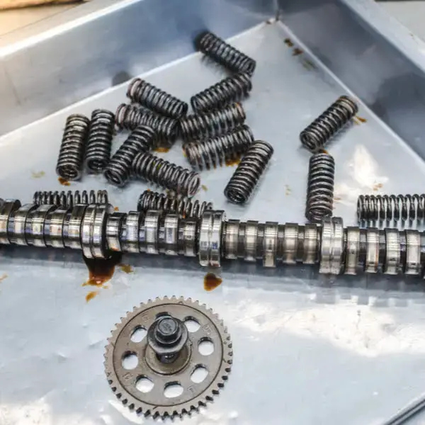
(Image credit: Engine Basics)
The P04DB code is typically triggered when the crankcase pressure readings deviate significantly from the historic trends stored in the Powertrain Control Module (PCM). In Ford vehicles equipped with a 6.7L diesel engine, the hall effect sensor is responsible for detecting the connection status of the crankcase ventilation system, triggering the code.
In some cases, the P04DB code may be accompanied by related codes like P04E2 (Crankcase Ventilation Hose Connection Sensor Circuit Low) and P04E3 (Crankcase Ventilation Hose Connection Sensor Circuit High), which help diagnose the specific issue with the system.
It’s important to note that the P04DB code is a known issue in the 6.7 Powerstroke engine, as well as other engines such as Cummins, Ecoboost, and 6.7 Diesel. Furthermore, it appears in various vehicle models, including popular ones like the Ford F150, F250, F350, Ford Focus, Ford Escape, and Dodge Ram.
Attention – P04DB Code On Ford 6.7L Diesel Engine
For owners of Ford vehicles affected by the P04DB code: Check if your car is covered under the customer satisfaction program 17M04. This program provides free repairs or replacements to address the issue.
P04DB Severity Explained: Is Immediate Attention Required?
The P04DB code is considered a moderate-level issue that does not require immediate attention but should not be ignored for an extended period. While you can still drive your vehicle with the code present, it is important to address the issue promptly.
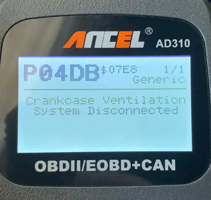
(Image credit: Explorer Forum)
Ignoring the P04DB code can lead to potential long-term consequences such as engine damage or decreased fuel efficiency. Seeking professional assistance and resolving the underlying cause of the code as soon as possible is recommended to ensure your vehicle’s longevity and optimal performance.
Signs Of The P04DB Code
The P04DB code manifests itself through various symptoms that can alert you to the underlying issue, such as:
- Check Engine Light (CEL) illuminated
- Reduced engine performance or power
- Engine misfires or rough idle
- Increased oil consumption
- Oil leaks or visible oil residue
- Unusual engine noise
- Remote start failure
- Poor acceleration
- Abrupt vehicle stops
- Shifting problems with jerking transmission
Read more: Misfire OBD2 codes – P0301, P0302, P0303, P0304, P0305
Common Causes Of The P04DB Code
There are several possible causes of the P04DB code:
- Disconnected or damaged CCV hoses
- Faulty PCV valve
- Clogged crankcase breather filter
- Incorrect placement of CCV
- Malfunctioning CCV sensors
Diagnosing And Fixing The P04DB Code
In this section, we will guide you through the process of diagnosing and fixing the P04DB code. Additionally, we will cover the necessary tools and parts, provide a step-by-step procedure, discuss the level of repair suitable for DIY enthusiasts, and give you an estimate of the potential cost involved.
Essential Tools And Parts
- OBD-II scanner
- Socket set
- Replacement PCV valve
- Crankcase ventilation hoses
- Crankcase breather filter
- Gaskets or seals (if necessary)
- Torque wrench
- Safety gloves and goggles
Step-by-Step Procedure
Reminder: Check the customer satisfaction program 17M04 if you own a 6.7 Powerstroke Ford. However, if your vehicle is not covered under the program and you would like to attempt a DIY fix, please follow the guide below:
Step 1: Begin by ensuring that the CCV components, including sensors and valves, are correctly positioned according to the manufacturer’s specifications.
Step 2: Inspect the CCV hoses for any disconnections or damage. Ensure all hoses are correctly connected and free from leaks or cracks. Repair or replace if necessary.
Step 3: Proceed to check the crankcase breather filter for clogs or restrictions. Clean or replace the filter as needed.
Step 4: Next, test the PCV valve for proper functioning. Replace the valve if necessary.
Step 5: Check the functionality of the CCV sensor. Replace it if it’s faulty.
Note:
In some vehicles, particularly certain 6.7 Powerstroke Ford models, if the CCV sensor fails, it might be necessary to replace the entire crankcase vent filter housing along with the sensor. This is due to the sensor being a pickup sensor that registers its connection.
It is advisable to consult the vehicle’s service manual or seek professional assistance to confirm the specific requirements and options for your vehicle’s CCV system.
DIY Repair Level And Estimated Costs
The level of DIY repair for the P04DB code is generally considered medium overall. Still, it can vary based on factors such as your mechanical experience and access to tools. While some individuals may feel comfortable performing the inspection and replacing components, others may prefer seeking the assistance of an expert or certified mechanic.
The estimated costs for repairing the P04DB code can differ depending on factors such as the vehicle model, the extent of the issue, and labor rates in your area. Here is a rough estimate of the main repair tasks:
| Repair Task | Estimated Cost |
| Crankcase breather filter replacement | $50 – $100 |
| PCV valve replacement | $60 – $150 |
| CCV sensor replacement | $100 – $250 |
Remember, these costs are approximate and may vary. Furthermore, if you’re uncertain or require additional assistance, consult a qualified professional who can accurately diagnose and repair the issue to ensure optimal results and avoid any potential complications.
Wrap Up
Congratulations! You’ve now gained valuable insights into the P04DB code and its implications for your vehicle’s CCV system.
With a better understanding of the P04DB code and its implications for your vehicle’s CCV system, you’re better equipped to address the issue promptly. Remember, taking action promptly when encountering the P04DB code can prevent further engine damage and ensure optimal performance.
If you found this guide helpful, share it with fellow car enthusiasts or anyone who may benefit from it. Feel free to leave comments or questions below; we’d love to hear from you.
To learn more about other trouble codes your car may face, use our OBD Code Lookup tool.
Stay proactive in maintaining your vehicle’s health, and happy driving!
Reference Sources
- Mopar1973Man.Com LLC, P04DB – Crankcase Ventilation System Disconnected – OBDII Error Codes.
- Ford-Trucks Forum, P04DB Code – Crank Case Vent.
- Ford Motor Company, Diagnostic Trouble Code (DTC) Descriptions.
- National Highway Traffic Safety Administration, 2018, Technical Service Bulletin: MC-10143112-9999.
P0305 – Cylinder 5 Misfire Detected
P0305 – Cylinder 5 Misfire Detected
The P0305 code triggers when cylinder #5 records a misfire. In general, misfires are the cause of major concern. Not only do they reduce your engine’s power, but they can lead to long-term damage (and subsequent costly repairs).
The severity of the P0305 trouble code depends on the frequency of the misfires and their ultimate cause. Use the steps below to help you diagnose the problem before it becomes more serious.
P0305 Code Definition
P0305 Code Definition (Generic): Cylinder #5 Misfire Detected
P0305 BMW Code Definition: #5 Cylinder Miss Fire
P0305 Ford Code Definition: Fault Cylinder ‘E’ – Misfire Detected
P0305 Nissan Code Definition: Cylinder #5 Misfire Detected
What Does P0305 Mean?
The cylinders in your engine are what produces the power. Fuel is injected into the cylinder and is combusted by the spark from the spark plug. The energy released in the combustion turns the crankshaft, generating power.
The cylinders in your engine work together to provide constant power to the crankshaft. When things are working correctly, they fire in sequence so smoothly the crankshaft’s RPM is consistent. A single misfire won’t have much impact on your system. Repeated or chronic misfires, however, will lead to significant loss of engine power.
Code P0305 triggers when the #5 cylinder misfires. On Fords, this is defined as Cylinder ‘E’. You’re likely to see it in combination with P0300, the general misfire code. Driving with a misfiring engine can damage its internal components, so this isn’t a code you want to ignore.
What Are The Symptoms Of The P0305 Code?
You can use the symptoms present with the P0305 code to guide your diagnosis. The most common symptoms include:
- Activation of the check engine light. If the light is solid, the misfire may be random or sporadic. A flashing check engine light indicates repeated misfires and is cause for more concern.
- Rough idle
- Hard starts
- Shaking or stumbling engine
- Jerks and hesitations during acceleration
- Reduced engine power
- Fuel odors in the exhaust
What Are The Causes Of P0305?
The most common causes of the P0305 OBD2 code are:
- Faulty or worn-out spark plugs
- Faulty wiring around the spark plugs
- Faulty ignition coils
- Faulty fuel injector
- Failed distributor
Other possible causes include:
- Leaks in the vacuum system
- Low fuel pressure
- Defective camshaft or crankshaft sensor
- Engine timing issues
- Faulty catalytic converter
- Fuel quality too low
- Fuel level too low
How Serious Is The P0305 Code?
The P0305 OBD2 code is severe. The drivability issues associated with the code can make it unsafe to operate your vehicle. Repeated misfires can also cause long-term engine damage. Stop driving your car immediately, and don’t use it again until you’ve repaired the cause.
How To Diagnose And Fix The P0305 Code
If the check engine light is solid and there are no drivability issues, clear the codes and test drive your car. The code may not return if the misfire was an isolated incident. Monitor your engine performance and continue with repairs if the code returns.
Tools you’ll need:
- OBD2 scan tool
- Basic tool kit (screwdriver, a ratchet set, socket set, etc.)
- Digital multimeter
- Fuel pressure gauge
- Compression tester
Method:
- Read the freeze frame data using the OBD2 scanner. Identify the conditions in which the code is initially triggered. If any other trouble codes are present, fix those first, which may be the root cause of the misfire.
- Check the wiring around the spark plugs and wiring harness. Re-connect any that are loose, and replace any that are frayed or damaged.
- Inspect the vacuum hoses in your engine for damage and leaks, feeling for issues in any hidden areas. If you find any leaking hoses, replace them. Please pay close attention to the ends, as well, and ensure they’re firmly connected.
- If you have individual coil packs, swap the cylinder 5 pack with the cylinder 4 pack. Clear the codes, then test drive and scan your vehicle. If the misfire moved to cylinder 4, you’ve identified the coil pack as the issue. Replace the coil pack, clear the codes, and test your vehicle again.
- Inspect the spark plugs. If they’re shiny with oil, carefully wipe them clean and replace them. Replace any spark plugs with black carbon build-up or visible corrosion.
- Test the spark plug wires with a digital multimeter. Remove each wire, connecting each multimeter lead to an end. Compare it with the specified reading in your vehicle’s manual. If more than 2 wires fail, replace the entire harness.
- Perform a compression test to check for mechanical issues. Burned valves, worn valve guides, and similar mechanical failures can lead to misfires.
- Check the timing chain. Ensure it’s properly aligned and that it hasn’t skipped any teeth.
- Verify that you’re using the grade of fuel specified in your vehicle’s manual. While this is a rare cause of the P0305 trouble code, fuel quality issues can cause misfires. If the fuel is incorrect, drain and flush your system, then refill it with the correct fuel type.
- Use a digital multimeter to check the fuel injectors. If the reading doesn’t match the specifications in your vehicle’s manual, replace them.
- Should the P0305 code return, the issue is most likely with your fuel system. Check the fuel pressure with a fuel pressure gauge. If it’s too low, your fuel pump may be failing. Take your vehicle to a mechanic for further diagnosis.
Common Mistakes To Avoid While Diagnosing The P0305 Code
Many mechanics immediately replace the spark plug or ignition coils when a misfire code triggers. While these are often the cause, you want to conduct a thorough diagnosis before jumping to any conclusions.
Tips To Avoid P0305 In The Future
Many times, misfires are caused by issues with the air-to-fuel ratio. Leaks in the vacuum system can cause these, as can be clogged or leaking components in the exhaust system. Periodic inspection of the hoses, wires, and valves in your system can help you stop problems before they happen.
Read more:
P1399 Honda – Random Cylinder Misfire Detected
P0440: Meaning, Symptoms, Causes, Diagnostics, and Fixes
B1342 Ford Code: Essential Insights For Ford Owners
B1342 Ford Code: Essential Insights For Ford Owners
Welcome, Ford owners, DIY mechanics, and auto enthusiasts! Today, we’re going to tackle a common code that might have left you scratching your head – the B1342 Ford code.
If you’ve ever seen this code pop up and wondered what it means for your vehicle, you’re in luck. We’re here to break it down for you in simple terms.
Join us as we explore what the B1342 Ford code is, the signs to look out for, what causes it, and how you can diagnose and fix it yourself.
Let’s get started!
B1342 Ford: A Quick Overview
Before we dive into the details, let’s take a quick look at a summary of the B1342 Ford code!
- Definition: ECU Is Defective
- Severity: Medium
- DIY Skill Level: Intermediate
- Continue To Drive?: Yes
- Estimated Repair Cost: $200 – $500
What Does The B1342 Ford Code Meaning?
The B1342 code on Ford vehicles is commonly associated with a configuration error or fault in the Engine Control Module (ECU). The ECU is a critical component responsible for managing various systems and components in your Ford vehicle, such as the anti-lock braking system (ABS), airbags, climate control, and more. A malfunction within these systems can trigger the B1342 code, alerting you to a potential problem.
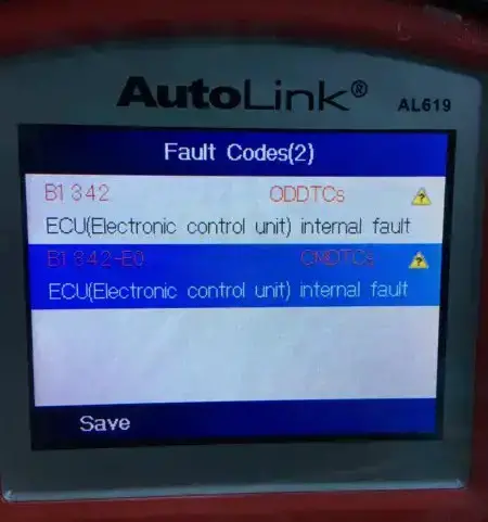
(Image credit: Explorer Forum)
The B1342 code commonly appears in several Ford models, including the Ford F150 (especially in the 2009 model year), Explorer, Escape, Expedition, Mountaineer Premier, and Crown Victoria. These models incorporate sophisticated electronic systems interacting with the ECU and BCM (Body Control Module), making them susceptible to triggering the B1342 code.
It’s worth noting that the appearance of the B1342 code doesn’t automatically pinpoint the exact component or system failure. It indicates that further diagnosis is required to identify the specific issue causing the code.
Can You Continue Driving With B1342 Ford?
The severity of the B1342 code is generally considered medium. While it does not indicate an immediate safety concern, it signifies a malfunction within the vehicle’s diagnostic system that can impact the performance of various systems.
Although you can continue to drive with the B1342 code present, it is not recommended to ignore it. Ignoring the code may lead to potential complications and adversely impact the functionality of the affected systems in the long run.
Read more: P1464 Ford Code: A Guide To Handling AC System Issues
Signs Of The B1342 Ford Code
The symptoms associated with the B1342 code in Ford vehicles can vary depending on the specific module that has malfunctioned within the diagnostic system.
Here are some common examples of symptoms observed in relation to this code:
| Malfunctioned Module | B1342 Code Symptoms |
| ABS Module | – ABS warning light turns on – Loss of traction control and stability control features – Braking system behaves unpredictably |
| Audio Control Module | – Issues with the audio system, such as no sound or distorted sound, may occur – Inability to adjust volume or change radio stations |
| Instrument Cluster | – Warning lights flicker or stay illuminated – Incorrect gauge readings (speedometer, fuel gauge, etc.) – Missing or inaccurate vehicle information display |
| Restraints Control Module (RCM) | – Airbag warning light illuminates – Airbags or seatbelt pretensioners may not function – Reduced passenger safety during a collision |
| Smart Junction Box (SJB) | – Multiple warning lights appear – Interior lights, power windows, or door locks malfunction – Unreliable functioning of electrical systems |
Read more: Ford Dashboard Symbols and Meaning (FULL list, Free Download)
Uncovering The Triggers Of B1342 Ford
Several underlying causes can activate the B1342 code in Ford vehicles. Here are some common causes often associated with this code:
- Faulty wiring or loose connections within the ABS module, RCM, SJB, or other related modules
- Power surges, voltage fluctuations, or other electrical system disruptions
- Malfunctioning ABS sensors, RSC sensors, or other relevant sensors
- Software bugs or programming errors within the ABS module, audio control module, instrument cluster, or other involved modules
- Faulty ECU or BCM
Read more: Complete List Of Ford OBD2 Codes for FREE Download
Diagnosing And Repairing B1342 Ford Code
Now that we’ve explored the meaning, severity, symptoms, and causes of the B1342 code in Ford vehicles, let’s delve into the essential steps for diagnosis and repair.
It’s important to note that the specific procedure may vary depending on the module that has a problem. Here’s a general outline:
Diagnostic Tools And Essential Parts
- OBD-II scanner
- Multimeter
- Wiring diagram and service manual specific to your Ford model
- Wiring harness connectors and terminals (if needed)
- Replacement of malfunctioning modules (ABS module, audio control module,..)
Step-by-Step Procedure
- Connect an OBD-II scanner or diagnostic tool to retrieve the B1342 code and any accompanying codes.
- Inspect the wiring connections and harnesses related to the module associated with the B1342 code. Look for loose connections, damaged wires, or corrosion.
- Perform electrical tests using a multimeter to check for voltage irregularities or shorts in the wiring. Refer to your Ford model’s wiring diagram and service manual for guidance.
- Check the sensors associated with the module for malfunctions or failures. Test the sensors using appropriate diagnostic procedures.
- If necessary, reprogram or replace the module following the manufacturer’s instructions. Inspect the module for any visible damage signs, such as burnt components or water intrusion.
- Once the repairs or replacements have been made, clear the codes using the OBD-II scanner.
- Perform a test drive to ensure the issue has been resolved and no codes reappear.
Remember, this is a general approach, and the specific steps may vary depending on the module involved. It’s recommended to consult the appropriate service manual and follow manufacturer guidelines for accurate diagnosis and repair.
DIY Repair Level And Estimated Costs
The level of DIY repair for the B1342 code diagnosis and repair procedure can range from moderate to advanced, depending on your technical skills and access to tools. If you’re unsure or uncomfortable with the process, it’s advisable to seek the assistance of an expert or professional mechanic.
As for the estimated costs, they can vary depending on the specific cause and required repairs. Here’s a rough breakdown of potential expenses:
| Repair Task | Estimated Cost Range |
| Diagnostic scan or professional assistance | $50 – $150 |
| Wiring harness connectors and terminals | $50 – $100 |
| Replacement of malfunctioning sensors | $50 – $200+ (including parts and potentially labor if needed) |
| Replacement of malfunctioning modules (e.g., ABS, audio, etc.) | $200 – $600+ (including parts and potentially labor if needed) |
B1342 Ford Infographic
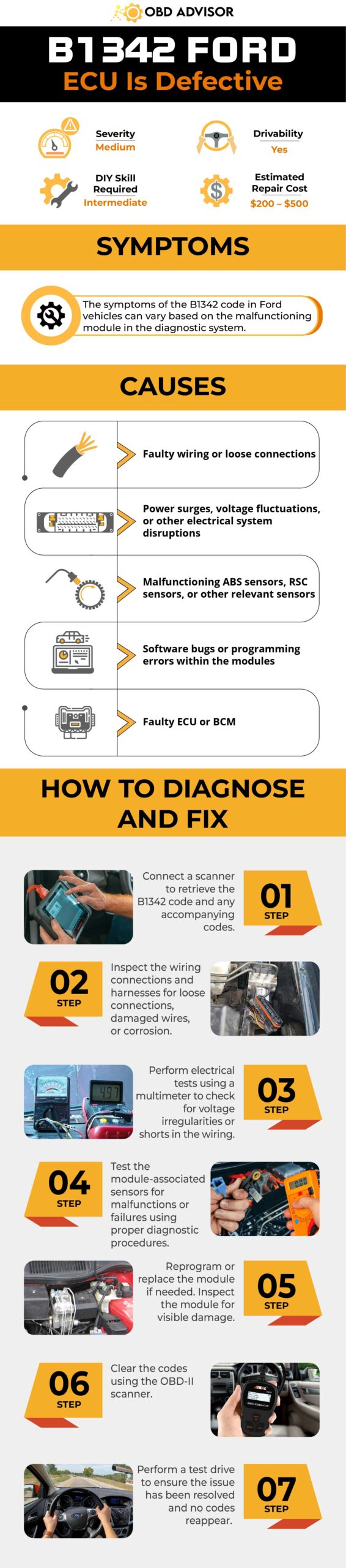
Final Thoughts
Great job on uncovering the meaning of the B1342 code in Ford vehicles! Now you know more about it and how to tackle the issue.
Remember, maintaining a healthy diagnostic system is crucial for the optimal performance of your Ford vehicle. If you ever see the B1342 code or face any other car problems you’re uncomfortable with, get help from a trusted mechanic or expert.
Have you successfully fixed the B1342 Ford code? Share your experiences in the comments below. Let’s talk and support each other with car diagnostics.
Stay safe on the road, and good luck fixing any issues!
Reference Sources
- Kelley Blue Book, OBD-II Trouble Code: B1342.
- National Highway Traffic Safety Administration, 2019, Safety Recall 19V-904.
- Ford Motor Company, 2011, TSB 11-3-3.
- Lima-City, Smart Junction Box (SJB).
- Reddit, B1342 Fault Code ABS Module Bad.
- 2CarPros, Code B1342.
P1780 Ford Code: Tackling Transmission Concerns Head-On
P1780 Ford Code: Tackling Transmission Concerns Head-On
Welcome to our guide, where we embark on a journey to decode the P1780 Ford code. As a fellow car enthusiast, I understand the frustration it can spark. But fret not! In this article, we’re stepping into the intricate world of automotive diagnostics, unraveling the puzzle of the P1780 code in your Ford.
With a blend of technical know-how and practical advice, you’ll be equipped to tackle this challenge head-on.
So, let’s dive into the P1780 Ford code and tackle it together, armed with knowledge and determination!
P1780 Ford Code: A Quick Overview
Check the overview of the P1780 Ford code below!
- Definition: Transmission Control Switch Circuit Out of Self Test Range
- Severity: Medium
- DIY Skill Level: Intermediate
- Continue To Drive?: Yes
- Estimated Repair Cost: $20 – $150
What Does The P1780 Code Mean On Ford?
The P1780 code signifies a Transmission Control Switch Out of Self-Test Range error in Ford vehicles. It points to a potential fault in the transmission control switch (TCS). This code is triggered when the transmission control switch fails to change states as expected.
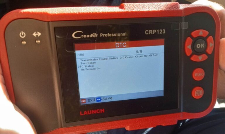
(Credit: f150forum.com)
The TCS is primarily situated on the shift plate or shift knob, enabling drivers to select different gears while on the move. Commonly denoted as “OD off” or “OD cancel,” or occasionally as “Tow/Haul” in certain trucks, this button serves a specific purpose. Primarily, it prevents the transmission from engaging in overdrive mode. When the P1780 code is set, it means that the TCS is experiencing a malfunction, a situation that can adversely affect the normal functioning of the transmission.
The P1780 code can manifest across various Ford models equipped with automatic transmissions. While not an exhaustive list, some of the Ford models that may encounter this issue include F-150, Explorer, Ranger, Mustang, etc.
Read more: P1464 Ford Code: A Guide To Handling AC System Issues
How Severe Is The Ford Code P1780?
The P1780 code indicating a TCS fault in Ford vehicles carries a moderate severity level. While it doesn’t pose an immediate safety risk, it can lead to transmission-related issues. It’s possible to drive with this code unaddressed. However, it could result in erratic gear changes, reduced fuel efficiency, and potential transmission overheating.
It’s advisable not to ignore this code and to have the TCS inspected and repaired by a qualified technician. Continued driving with a malfunctioning TCS might exacerbate transmission problems, potentially leading to costly repairs. Addressing the issue promptly ensures consistent transmission performance and prevents further complications down the road.
What Are The Symptoms Of The P1780 Codes On Ford Vehicles?
Experiencing the P1780 code in a Ford vehicle may be accompanied by the following symptoms:
- Check engine light
- Incorrect or erratic shifting
- Inability to shift gears
- Illuminated overdrive light on the dashboard
- Reduced fuel efficiency
- Transmission control indicator lamp
What Causes Of The P1780 Ford Code?
The P1780 code in Ford vehicles can arise from various underlying causes, including:
- Faulty TCS
- Wiring or connector issues related to the TCS
- ECM issues
How To Diagnose And Fix The P1780 Ford Code?
Confronting the P1780 code within your Ford vehicle demands a methodical strategy for effective resolution. So, here’s a breakdown of the essential tools and parts, followed by a step-by-step guide for the procedure.
Essential Tools And Parts
To successfully diagnose and repair the P1780 code, you’ll need the following tools and parts:
- Shift knob or shift plate replacement (if needed)
- Wiring and connector
- OBD-II scanner
- Multimeter
- Wiring diagram
Step-by-Step Procedure
Step 1: Fuse inspection
- Turn off the key
- Measure fuse resistance with a value of less than 5 ohms
- If resistance is below 5 ohms, replace the fuse
Step 2: Short to ground check
- Disconnect the ECM
- Measure resistance between PIN 41 and ground
- Resistance should exceed 10,000 ohms
- If it’s less, repair the circuit
Step 3: Voltage test for TCS circuit
- Disconnect the ECM
- Turn the key to the on position
- Measure the voltage between Pin 41 and the ground while cycling the TCS switch
- If voltage cycles, the ECM requires replacement
Step 4: Open circuit examination
- Turn off the key
- Disconnect the central junction box and transmission control switch
- Measure resistance between CJB fuse 2.13 Pin 10 and power side of TCS Pin 2
- Measure resistance between CJB fuse 2.13 Pin 10 and power side of TCS Pin 1
- Both resistances should match. If not, repair the circuit
Step 5: Short to power check
- Measure resistance between Pin 41 and Pin 1
- Resistance should surpass 10,000 ohms
- If not, repair the circuit
If these steps fail to identify the issue, consider replacing the transmission control switch. In case of uncertainty during testing, follow the steps sequentially and retest accordingly. This thorough approach ensures accurate diagnosis and effective resolution.
The TCS is positioned at various locations on Ford models, commonly integrated into the shift knob or shift plate. Replacing the attached assembly is typically required, as the switch is generally affixed and cannot be individually replaced.
Step 6: Clear code(s) and test drive
Clear the codes with the OBD-II scanner and test drive the vehicle to ensure proper shifting.
Note:
- Double-check the wiring connections before replacing the TCS.
- Be cautious while working around the transmission components.
Read more: P1132 Ford Code: Ignition Issues Explored
DIY Repair Level And Estimated Costs
If you’re confident in your automotive skills, you might consider tackling the issue. Nevertheless, if uncertainties arise, seeking a mechanic’s expertise is advisable.
For those seeking professional repair assistance, costs can vary depending on the specific problem and your location. However, here’s a basic idea of how much you might need to pay for the main repair tasks:
| Repair Task | Estimated Cost Range |
| Shift knob or shift plate replacement | $50 – $200 |
| Check and Repair Wiring | $50 – $150 |
| ECM Replacement (rarely) | $200- $1000 |
P1780 Ford Summarize Infographic
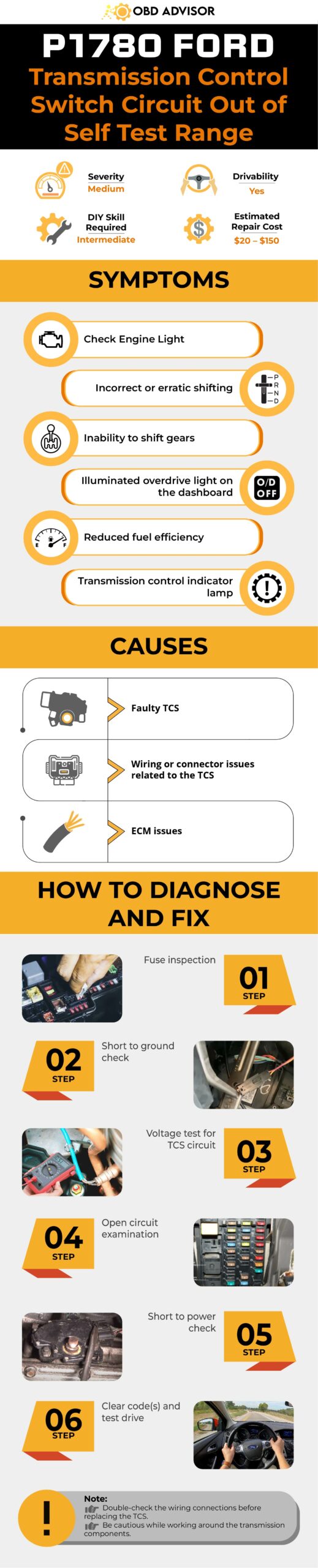
Final Thoughts
Armed with insights into the P1780 Ford’s meaning, symptoms, and possible causes, you’re now poised to tackle this challenge head-on. Whether you’re a hands-on enthusiast or prefer professional intervention, addressing the issue is paramount.
Join the conversation – share your experiences or questions in the comments below. Additionally, if this guide proves invaluable, spread the know-how and invite others to explore. Keep the wheels turning smoothly and the road ahead clear. Drive confidently!
Reference Sources
- JustAnswer, P1780 Ford Code Diagnosis
- Yourmechanic, Is It Safe to Drive With the Overdrive Light On?
- Bluespringsfordparts, DTC Decoded: P1780 – Transmission Control Switch Circuit
P1009 Honda Code: VTC System Troubleshooting And Solutions
P1009 Honda Code: VTC System Troubleshooting And Solutions
Discover insights into the P1009 Honda code intricately linked with your Honda’s VTC (Variable Valve Timing Control) system. If you’ve come across this code, there’s no need to worry.
Within this article, we’ll thoroughly explore the P1009 Honda code, its correlation with the VTC system, its implications, severity, symptoms, causes, diagnosis, and repair steps.
Leveraging my extensive experience as a seasoned mechanic, I’m here to provide guidance and knowledge to navigate this challenge.
Let’s get started!
P1009 Honda Code: A Quick Overview
Check the summary of the Honda P1009 code provided below!
- Definition: VTC Advance Malfunction
- Severity: Medium
- DIY Skill Level: Intermediate
- Continue To Drive?: Yes (short-term)
- Estimated Repair Cost: $30 – $300
What Does The P1009 Code Mean On Honda?
The diagnostic trouble code (DTC) P1009 in Honda vehicles is an indication of an issue related to the timing control of the variable valve system. More specifically, this code points to problems within the Variable Valve Timing Control (VTC) system.
The VTC system plays a crucial role in determining the opening of the intake camshaft, effectively managing the amount of oil that flows into the camshaft. This control over oil flow is pivotal in optimizing valve timing for the engine’s performance.
The VTC actuator, a central component of this system, is operated through oil pressure. It dynamically adjusts valve timing to maximize power output and ensure efficient operation under varying driving conditions. The valve timing, crucial for proper engine functioning, is directly influenced by the prevailing driving conditions.
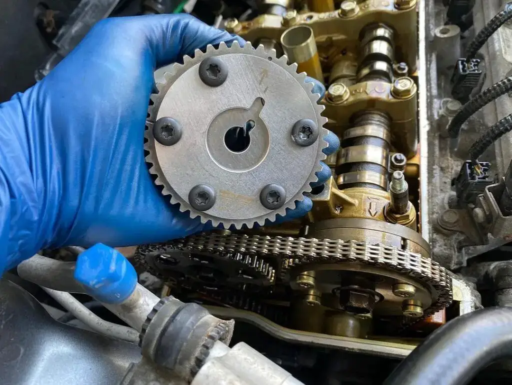
A significant player in maintaining precise camshaft timing is the Camshaft Position (CMP) sensor. This sensor collaborates with the Powertrain Control Module (PCM) to ensure accurate monitoring of the camshaft’s timing. The PCM provides control commands that are continuously monitored to set the correct direct value for camshaft timing.
When the camshaft phase becomes excessively advanced or deviates abnormally from the direct value, the system detects and stores the P1009 code. This DTC serves as an alert that a malfunction exists within the VTC system. To identify this malfunction, a diagnostic scanner is employed to read the code and highlight the issue.
The P1009 code has been known to appear in various Honda models, indicating potential problems within the VTC system. Some of the Honda models that are commonly associated with the P1009 code include CRV, Accord, Element, Civic, etc.
How Severe Is The Honda Code P1009?
The P1009 code indicates a moderate level of severity. While it may not immediately make your vehicle inoperable, it should not be ignored. Ignoring this code could lead to diminished engine performance, reduced fuel efficiency, burning oil and potential long-term damage to the engine components related to the VTC system.
Is it safe to drive with the Honda P1009 code? – Yes, you can, but short-term only. However, it’s not advisable. Ignoring the issue could result in higher repair costs down the road. To prevent further damage and maintain optimal performance, it’s recommended to have the issue diagnosed and repaired by a qualified mechanic as soon as possible.
What Are The Symptoms Of The P1009 Codes On Honda Vehicles?
When the P1009 code appears in a Honda vehicle, it can manifest through various symptoms, indicating potential issues within the VTC system. These symptoms may include:
- Check engine light
- Reduced power (particularly during acceleration)
- Rough idling
- Poor fuel efficiency
- Car vibration
- Engine misfires
Read more: A Full List Of Honda OBD2 Codes [Generic + Manufacturer-specific] for FREE
What Causes The P1009 Honda Code To Be Set?
The P1009 code can be triggered by various underlying causes, leading to issues in the VTC system. Some common causes include:
- Wiring or connector faults related to the VTC circuit
- Faulty VTC actuator
- CMP sensor issues
- Oil flow restrictions
- Timing chain/belt problems
- PCM malfunction
How To Diagnose And Fix The P1009 Honda Code?
Dealing with the P1009 code in your Honda needs a clear plan. This part explains the important tools and the step-by-step process. We’ll also talk about costs. By following these steps, you can take care of the P1009 code and keep your Honda running well.
Essential Tools And Parts
To successfully diagnose and repair the P1009 code, you’ll need the following tools and parts:
- OBD-II scanner
- Basic hand tools
- New VTC actuator (if needed)
- Camshaft position sensor (if required)
- Engine oil and oil filter
Step-by-Step Procedure
- Visual inspection: Inspect wiring, connectors, and the VTC actuator for visible damage or corrosion.
- Check the VTC strainer for clogging: If it is clogged, clean it.
- Check oil level: Ensure the engine oil level is correct and the oil quality is good. Replace engine oil and oil filter if needed.
- VTC actuator replacement: If the actuator is faulty, replace it following manufacturer guidelines.
- CMP sensor replacement: If needed, replace the sensor according to your vehicle’s specifications.
- Oil flow check: Confirm proper oil flow to the VTC actuator and address any restrictions.
- Clear Codes: Use the scanner to clear the codes and restart the engine to see if the issue persists.
Note:
- Before you start fixing the problem, remember to write down all the freeze data and on-board snapshots. Also, take a good look at the general troubleshooting instructions.
- If you see both DTC P0341 and DTC P1009, work on the P1009 issue first. Then, recheck the P0341 problem.
Read more: P1399 Honda – Random Cylinder Misfire Detected
DIY Repair Level And Estimated Costs
If you are a DIYer and feel comfortable working on engine components, you might consider addressing the P1009 code independently.
When uncertainties arise during the repair process, or you lack experience, seeking an experienced mechanic’s skills is strongly advised.
| Repair TaskEstimated CostVTC Actuator Replacement$150 – $300 (parts and labor)Camshaft Position Sensor Replacement$50 – $100 (parts and labor)Engine Oil Replacement$30 – $50 (oil and filter)Wiring and Connector Repair$50 – $150 |
P1009 Honda Infographic
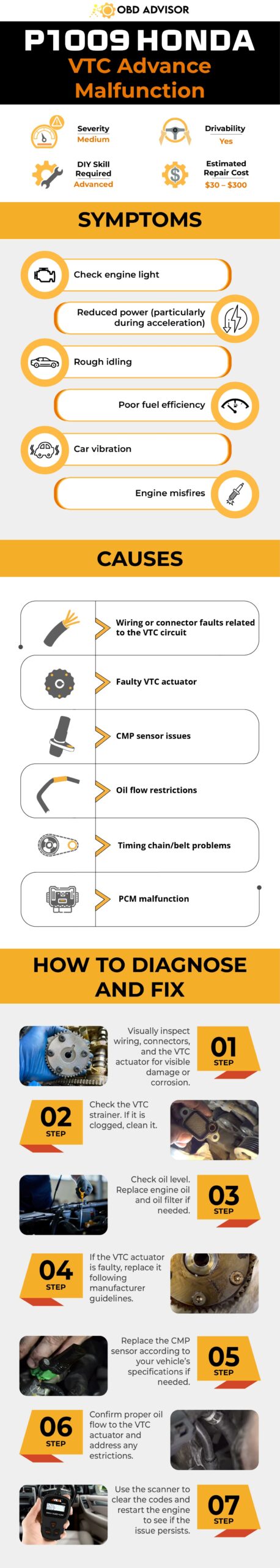
Final Thoughts
Knowing and fixing codes like P1009 is super important to keep your car running great. The VTC system affects when the engine does stuff, so fixing it quickly really matters.
Whether you’re a seasoned DIY enthusiast or prefer the expertise of a skilled mechanic, tackling the P1009 code ensures a smoother driving experience and prevents potential long-term issues.
Sharing your experiences or questions in the comments. If this guide has been a helpful companion, consider passing it on to fellow Honda owners. Your commitment to your car’s health ensures smoother rides and exciting journeys on the horizon.
Reference Sources
- HCRV, DTC P1009 VTC Advance Malfunction.
- HELLA, Camshaft Position Sensor.
- J.D. Power, What Happens When a Car Misfires.
Honda OBD1 Codes: A Comprehensive List For Quick Troubleshooting
Honda OBD1 Codes: A Comprehensive List For Quick Troubleshooting
Does the check engine light bother you, and you’re just curious about reading the Honda OBD1 codes?
Look no further!
In this post, we have compiled a clear and concise list of Honda OBD1 codes to help you diagnose any issues with your car quickly. We also tell you how to read and erase trouble codes in your Honda model.
But that’s not all – This codes list is totally FREE to download.
So, let’s begin!
Honda OBD1 Codes List and Definition [FULL]
Free Download: Full Honda OBD1 Trouble Codes List and Meaning PDF
Note: Use the search box in the table below to quickly find the specific code you’re looking for.
| Code | Meaning |
|---|---|
| Codes 0 and 11 | Electronic control module (ECM) |
| Code 1 | Heated oxygen sensor A |
| Code 2 | Oxygen content B |
| Codes 3 and 5 | Manifold absolute pressure |
| Code 4 | Crank position sensor |
| Code 6 | Engine coolant temperature |
| Code 7 | Throttle position sensor |
| Code 8 | Top dead center sensor |
| Code 9 | No.1 cylinder position sensor |
| Code 10 | Intake air temperature sensor |
| Code 12 | Exhaust recirculation system |
| Code 13 | Barometric pressure sensor |
| Code 14 | Idle air control valve or bad ECM |
| Code 15 | Ignition output signal |
| Code 16 | Fuel Injector |
| Code 17 | Vehicle speed sensor |
| Code 19 | A/T lock-up control solenoid |
| Code 20 | Electric load detector |
| Code 21 | V-TEC control solenoid |
| Code 22 | V-TEC pressure solenoid |
| Code 23 | Knock sensor |
| Code 30 | A/T FI signal A |
| Code 30 | A/T FI signal B |
| Code 41 | Heated oxygen sensor heater |
| Code 43 | Fuel supply system |
| Code 45 | Fuel supply metering |
| Code 48 | Heated oxygen sensor |
| Code 61 | Front heated oxygen sensor |
| Code 63 | Rear heated oxygen sensor |
| Code 65 | Rear heated oxygen sensor heater |
| Code 67 | Catalytic converter system |
| Code 70 | Automatic transaxle |
| Code 71 | Misfire detected cylinder 1 |
| Code 72 | Misfire detected cylinder 2 |
| Code 73 | Misfire detected cylinder 3 |
| Code 74 | Misfire detected cylinder 4 |
| Code 75 | Misfire detected cylinder 5 |
| Code 76 | Misfire detected cylinder 6 |
| Code 80 | Exhaust recirculation system |
| Code 86 | Coolant temperature |
| Code 90 | Evaporative Emission Control System Leak Detected (EVAP) |
| Code 91 | Fuel Tank Pressure Circuit |
| Code 92 | Evaporative emission control system |
Honda OBD1 Connector Location
Honda OBD1 plug is found on the passenger side beneath the glove box. The plug has a blue plastic casing and houses two connectors. One of the connectors is more extensive and has 3 double pins, whereas the other has 2 double pins. The connector to use is the 2 double pins.
How to Pull Honda OBD1 Codes Without a Scanner
Firstly, before embarking on the journey to read the OBD1 codes, you’ll need the following items: a paper, pen, and unrolled paper clip.
Here is how to go about the self-diagnostic test:
- Fold the unrolled paper clip into a U or V shape and insert its ends on the 2 double pin connector. It should form a loop between the right and left pins.
- Turn the key through 2 clicks to start the ignition without cranking the engine.
- Next, fix your eyes on the instrument cluster, taking a keen interest in the check engine light.
- Count the number of flashes to identify the error code.
You should note that long flashes represent the first digit in a two-digit code. For example, two long flashes would indicate number two as the first digit of the two-digit code. The second digit of the code is identified through short flashes.
Single-digit codes are interpreted by counting short interval flashes. For multiple trouble codes, the signal to the consecutive trouble code is a much longer pause between the two codes.
- Record the error codes using a pen and paper.
- Finally, you can look up the trouble codes in the section down below, or you can Google them up on Honda’s website.
How to Clear a Honda OBD1 Code
After fixing the faulty component or sensors, you need not be frustrated or distracted by the flashing check engine light. Here are some of the ways that you could use to eliminate the error codes:
1. Disconnecting the negative battery terminal
Disconnect the negative battery terminal for 10 to 15 seconds, then reconnect it to resets the ECU. This action eliminates the trouble codes. However, this method suffers several drawbacks, including rough driving for about 50 miles before the ECU relearn its values. Secondly, you’ll need to reconfigure your radio stations, as radio codes are lost during the reset.
2. Pulling out the ACG or alternator sense fuse
This is a much safer reset method, and you won’t have to reconfigure your radio stations once it’s done. Here is how to go about it:
- Identify the fuse compartment located near the driver side kick panel.
- Uncover the fuse box and locate the number used to represent the ACG or the alternator sensor fuse. This information is indicated beneath the circuit schematic attached under the fuse box cover.
- Locate the fuse and dislodge it before reinserting it.
This will reset the ECU. You can crank up the engine and let it idle for about 10 minutes for the ECU to relearn its values, or you could take the vehicle on a short drive.
Final Thoughts
I hope that our Honda OBD1 codes post has been a valuable guide for diagnosing and fixing any issues with your Honda vehicle. By understanding what your car says through the OBD1 code and understanding how to interpret them, you can keep your vehicle running smoothly for years to come.
If you have any questions or comments about our Honda OBD1 codes list, we would love to hear from you. Feel free to comment below and share your experiences troubleshooting your Honda vehicle.
And if you’re finding the proper scan tool for your vintage Honda, check out our post about the best OBD1 scanners in 2024.
Thanks for reading our post!
References:
- OBD1 Trouble Codes for Honda CRX/EF/Civic 1988-1991, Honda-tech.com
- MIL (Flash) Trouble Codes Honda, Alflash.narod.ru
P1168 Nissan Code: Discover Meaning, Causes & Simple Repair Steps
P1168 Nissan Code: Discover Meaning, Causes & Simple Repair Steps
If you’re a Nissan owner encountering the P1168 code, you’re probably looking for answers. Don’t worry—I’m here to help!
Before you go ahead and replace the O2 sensor right away, let’s take a step back. It’s important to understand the root cause of the issue before jumping to any conclusions.
In this article, my goal is to guide you through the ins and outs of the P1168 code. Together, we’ll explore what’s going on behind the scenes. Plus, I’ll provide you with practical tips to diagnose and fix the problem.
So, let’s dive right in and get to the bottom of the P1168 Nissan code!
P1168 Nissan: A Quick Overview
Check out the handy summary box below for a quick overview of the P1168 Nissan Code!
- Definition: Closed Loop Control Function Bank 2
- Severity: Medium
- DIY Skill Level: Intermediate
- Continue To Drive?: Yes
- Estimated Repair Cost: $50 – $100
What Does The P1168 Code Mean On Nissan?
The P1168 code found in Nissan vehicles indicates a potential problem within the Air Fuel Ratio (A/F) sensor or Heated Oxygen Sensor (HO2S) circuit. When the engine control module (ECM) detects that the closed-loop control function for bank 2 fails to operate, even under the specified conditions while driving, this code is triggered. This code is mostly common in Nissan Titan, Xterra, Murano, Pathfinder, and Nissan Maxima vehicles.
The A/F sensor, or HO2S, is a critical component in the fuel system as it measures the oxygen content in the exhaust gases. This information helps the ECM adjust the air-fuel mixture for optimal combustion efficiency. Therefore, encountering the P1168 code suggests a fault with the A/F sensor or its circuitry.
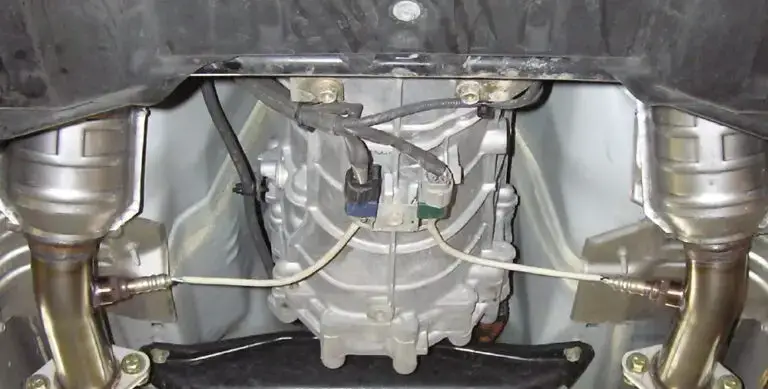
(Image credit: My350z.com forum)
In a closed-loop condition, the ECM continuously monitors sensors to make real-time adjustments to fuel delivery. A closed-loop fault indicates an issue with the A/F sensor or HO2S circuit, disrupting the closed-loop control process.
Additionally, it’s worth noting that the P1168 code may be accompanied by other codes like P0501 (related to the vehicle speed sensor) and P1286 (related to the engine coolant temperature sensor). These additional codes suggest potential issues with the oxygen sensor system and engine coolant temperature regulation, impacting fuel delivery and engine performance.
Is The P1168 Nissan Code Severe?
The severity level of the P1168 Nissan code can be considered moderate. Although it signifies an issue with the A/F sensor or HO2S circuit, it does not imply immediate danger or render the vehicle undrivable.
Some of you might come across several forum discussions suggesting that the P1168 code is not a big deal and you can keep driving without any worries. They even state that the P1168 code only indicates that your Nissan’s catalytic converters might be operating more efficiently than stock, reducing the risk of blowback into the engine. Moreover, there’s an opinion that you shouldn’t worry about this code if you live in a non-emissions county.
However, let me offer you some friendly advice from a mechanic’s perspective. While you’re good to go (for A LITTLE WHILE) with the P1168 code, it’s still a good idea to address the issue sooner rather than later.
While driving with this code won’t pose immediate risks, you may experience decreased fuel efficiency and potential impacts on your vehicle’s performance. To avoid further complications, it’s best to diagnose and repair the issue as soon as possible. Taking proactive measures will prevent more severe issues from arising down the road.
What Are The Warning Signs Of The P1168 Nissan Code?
Beware of these telltale signs that could point to the presence of the P1168 Nissan code:
- Check Engine Light (CEL) illuminated
- Reduced engine performance
- Poor fuel efficiency
- Rough idle
- Abnormal exhaust emissions
- Service Engine Soon (SES) light illuminated (in some cases)
Read more: Nissan Dashboard Warning Lights and Meanings (FULL list, FREE Download)
What Causes The P1168 Nissan Code?
Here are some potential causes of the P1168 Nissan code:
- Open or shorted circuit in the heated oxygen sensor 1 bank 2
- Malfunctioning heated oxygen sensor 1 bank 2
- Faulty heated oxygen sensor 1 heater bank 2
How To Diagnose And Fix The P1168 Nissan Code
In this section, we’ll walk you through the steps to effectively troubleshoot and resolve the P1168 Nissan code. Let’s get started on getting your Nissan back on the road with confidence.
Essential Tools And Parts
- A/F sensor for bank 2
- Sensor gasket or seal
- Electrical connectors
- Wire connectors
- Wrench set
- Wire cutters
- Electrical tape
- Electrical cleaner
- Jack and jack stands
Step-by-step Procedure
Step 1: Get access to the A/F sensor. It is often located before the Catalytic Converter on Bank 2. You can access it conveniently through the driver’s side wheel well.
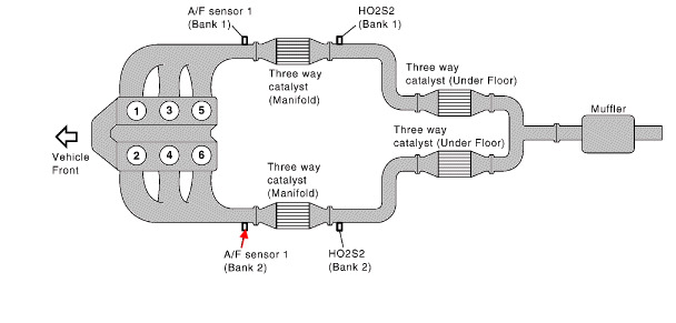
 Check this diagram to locate your Nissan’s A/F sensor 1 bank 2.
(Image credit: justanswer.com)
Step 2: Take a close look at the sensor’s electrical connector and wiring harness. Look for any signs of loose, broken, or damaged wires. Ensure that the connector is securely plugged in.
Step 3: Locate the ground wire, usually black in color, and trace it to its connection point on the vehicle’s chassis or engine. Make sure it is firmly attached without any corrosion or looseness. If needed, clean the connection and reattach the wire securely.
Step 4: Use a multimeter to test the wiring for any issues to ensure there is no discontinuity or abnormal resistance.
Step 5: If the above checks do not reveal any issues and the problem persists, it may be necessary to replace the sensor.
Start by unplugging the electrical connector from the sensor.
Then, carefully unscrew the sensor from the exhaust pipe using an appropriate wrench or socket.
Take note of the sensor’s orientation and the number of wire connectors for the replacement process.
Step 6: Clear the error codes and perform a test drive to verify if the issue has been resolved.
Note: Choose a trusted manufacturer for your replacement O2 sensor to ensure quality and compatibility. Bosch products are known for their quality and compatibility, making them a reliable choice.
Tips: I have a helpful tip for working with A/F sensors! It’s all about using anti-seize, which is a special lubricating compound that helps prevent seizing or sticking of threaded components. Here are some tips for using anti-seize effectively:
- Use a bit of anti-seize on the threads, but keep it off the sensor.
- Choose anti-seize specifically formulated for O2 sensor temperatures.
- Look for included anti-seize tubes in a reputable brand’s packaging (e.g., Bosch, Denso).
- Check if store brand options include anti-seize (e.g., Duralast). If not, purchase a suitable product separately.
Estimated Repair Costs For P1168 Code In Nissan Vehicles
Diagnosing and repairing the P1168 code in Nissan vehicles can be approached as a DIY project, but it does require some automotive knowledge and skills. Accessing the A/F Sensor and inspecting the wiring and grounding are relatively straightforward while replacing the O2 sensor, if necessary, requires more skill and knowledge.
It’s recommended to assess your comfort level and consider seeking professional help if needed. This approach can help ensure that the P1168 code is addressed effectively and avoid unnecessary expenses.
Here’s a general overview of estimated costs for labor and main repair tasks. Please remember that these figures are approximate and can vary based on factors like location and vehicle model.
| Repair Task | Estimated Cost |
| Diagnostic Fee | $50 – $150 |
| Wiring and Harness | $50 – $300 |
| A/F Sensor | $70 – $300+ |
| A/F Sensor Replacement (Labor cost) | $75 – $150 per hour |
P1168 Nissan Infographic
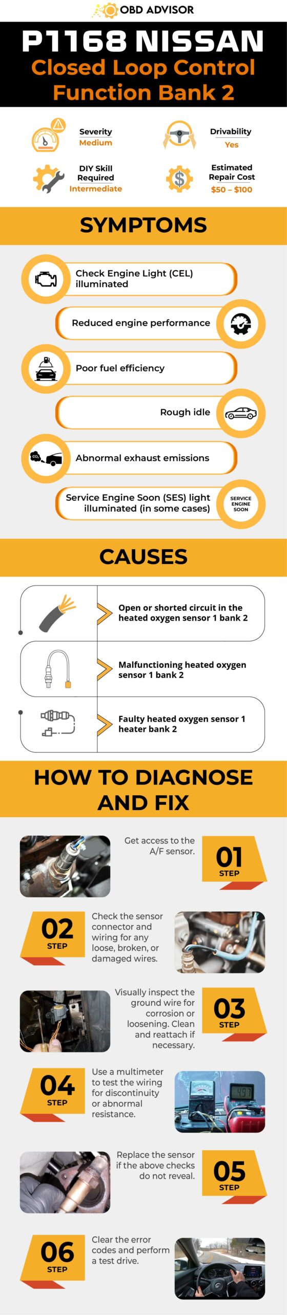
Final Thoughts
In conclusion, diagnosing and fixing the P1168 Nissan code can be a rewarding DIY project. If you have the know-how and confidence, go for it! Remember to prioritize safety and use the right tools.
If you prefer extra support or lack the necessary skills, don’t hesitate to bring in a professional mechanic. They’ll help you get your Nissan running smoothly again.
Whether you choose the DIY route or seek professional assistance, the goal is to resolve the P1168 code and ensure your Nissan is in top shape.
Ready to take on the challenge? Get your hands dirty and enjoy the satisfaction of a job well done!
Feel free to ask if you need more advice or have questions along the way. Best of luck with your P1168 code repair!
References Sources
- JustAnswer, What does a closed loop control fault mean (P1168)? – Answer by Nissan Expert Ron Z.
- Tire Review Magazine, 2011 May 6, Fuel System Definitions and Diagnostic Trouble Codes.
C1201 Toyota Code: How to Tackle Engine Control Problems
C1201 Toyota Code: How to Tackle Engine Control Problems
Prepare to tackle the C1201 Toyota code with our comprehensive guide. If you’ve encountered engine control problems, this article serves as your path to a solution. We’ll explore the likely culprits, provide a detailed diagnostic process, and offer effective remedies for the C1201 code.
Let’s dive in for more details!
C1201 Toyota: A Quick Overview
Here’s an overview of the C1201 for Toyota. Check it out!
- Definition: Engine Control System Malfunction
- Severity: Medium
- DIY Skill Level: Intermediate
- Continue To Drive?: No
- Estimated Repair Cost: $50 – $500
What Does the C1201 Mean in Toyota Vehicles?
C1201 is a common On-Board Diagnostics II (OBD-II) code that relates to the vehicle’s Engine Control Module (ECM/ECU). The C1201 code is predominantly associated with Toyota vehicles, including popular models like the Camry, Corolla, RAV4, Tundra, Sienna, and Highlander, among others. This code points to a problem with the engine control system’s performance. Specifically, it indicates a malfunction in the ECM/ECU’s internal circuitry. This can disrupt the vehicle’s engine management, potentially leading to issues with engine performance, fuel efficiency, and emissions.
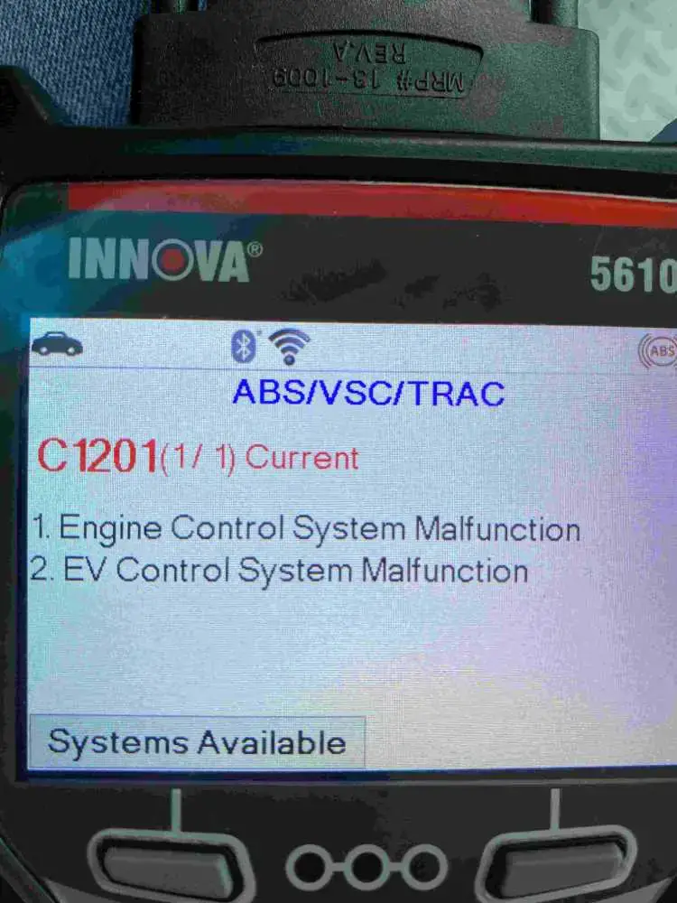
This code would be triggered when the engine control system malfunction signal lasts for 5 seconds. Simultaneously, a fail-safe function could activate. This function takes precautionary measures to ensure safety and prevent further damage to the vehicle. In the case of the C1201 code, the fail-safe function prohibits the operations of the Vehicle Stability Control (VSC) and Traction Control (TRC) systems.
How Serious is the C1201 Toyota Code?
The severity of the C1201 code in Toyota vehicles is high. Additionally, it’s unwise to continue driving with this code set. This code points to an issue with the engine control system, potentially impacting engine performance, fuel efficiency, and emissions. More importantly, it triggers the fail-safe function, disabling the VSC and TRC systems, which can compromise your vehicle’s stability, especially in adverse road conditions.
Our strong recommendation is not to delay addressing the C1201 code. Continuing to drive with it can lead to further complications, reduced safety, and potentially costly repairs in the future. Having your vehicle inspected and repaired by a qualified technician promptly is the best course of action to ensure your Toyota operates safely and efficiently.
What are the Signs of the C1201 Toyota Code?
When the C1201 code appears in your Toyota vehicle, it may manifest through various symptoms, including:
- Illumination of the check engine light
- Decreased engine performance
- Reduced fuel efficiency
- Unstable or rough engine idling
- Difficulty starting the engine
- Increased exhaust emissions
- Disabled VSC and TRC systems
What are the Causes of the C1201 Code in Toyota Vehicles?
The C1201 code can be triggered by several underlying causes, such as:
- Faulty ECM/ECU
- Wiring or connector issues in the engine control system
- Voltage supply problems to the ECM
Read more: Toyota OBD1/OBD2 Codes List [FREE DOWNLOAD]
How To Diagnose and Repair C1201 Toyota Code?
In this section, we’ll guide you through the necessary steps to diagnose and fix the P0462 code in your vehicle, equipping you with the understanding and tools required to resolve this problem efficiently
Diagnostic Tools and Essential Parts
To diagnose and repair the C1201 code in your Toyota, you’ll need the following tools and parts:
- OBD-II scanner
- Multimeter
- Basic hand tools (screwdrivers, pliers, etc.)
- Wiring diagram for your specific Toyota model
Step-by-Step Guide
- Begin by connecting the OBD-II scanner to your vehicle’s diagnostic port to retrieve the trouble codes and confirm the presence of C1201.
- Inspect the wiring and connectors in the engine control system for any visible damage or corrosion. Repair or replace as needed.
- Check the voltage supply to the ECM. Ensure it is within the specified range by repairing the wiring, fuse, or relay.
- Clear and rescan to know whether the code reappears or not. If all electrical components check out and the code still comes back, the issue may lie with the ECM itself. Replace the ECM following the manufacturer’s guidelines and program it as necessary.
Note:
- You can consult this TSB exclusively for this C1201 Toyota code for more details.
- Consult your vehicle’s service manual for specific instructions and diagrams related to your Toyota model.
- Ensure safety precautions, such as disconnecting the battery, are taken before working on electrical components.
- If you suspect your ECM needs replacement, it’s best to consult a professional. ECM tasks like replacement and reprogramming are complex and not suitable for DIY attempts.
DIY Repair Level and Estimated Costs
Diagnosing the C1201 code can be moderately challenging for DIY enthusiasts with some mechanical and electrical knowledge. However, replacing the ECM may require advanced skills and equipment, so if you have to replace the ECM, have a skilled mechanic perform that to ensure the job is done correctly and to avoid costly mistakes.
Estimated repair costs can vary widely, but here’s a rough breakdown:
| Repair Task | Estimated Cost |
| Repairing wiring/connectors | $50 – $150 |
| ECM replacement and programming | $500 – $1,500 |
Conclusion
In this article, we’ve shed light on the C1201 code in Toyota vehicles, providing insights into its meaning, severity, symptoms, and possible causes. We’ve also outlined a step-by-step procedure for diagnosis and repair, along with essential tools and parts you’ll need. While some aspects of addressing this code can be tackled by DIY enthusiasts, it’s essential to approach complex tasks, such as ECM replacement, with caution and professional guidance. Remember, timely attention to the C1201 code ensures your Toyota continues to run smoothly and safely on the road
If you found this article helpful, please consider sharing it with others who may benefit from this information. And if you have any questions or insights to share, don’t hesitate to drop a comment below.
To explore more about other DTCs, simply head over to our OBD2 code lookup for a comprehensive guide to automotive troubleshooting.
Reference Sources
Toyota Gambia, Brake Assist & Traction Control (TRC).
Toyota Motor Corporation, Vehicle Stability Control System. In RAV4 Repair Manual.
Toyota Arlington, What Does the VSC Light on My Toyota Mean?
GM OBD1 Codes List [Free Download]
GM OBD1 Codes List [Free Download]
Whether you own a classic Chevrolet, Cadillac, or any other GM model, understanding the OBD1 codes specific to your vehicle is crucial for effective troubleshooting and maintenance.
With our complete list of OBD1 codes, you can gain the knowledge and insights needed to decipher GM OBD1 codes, empowering you to take control of your GM car’s health and performance.
Towards the end of the article, you can perform a self-diagnostic test with or without a scanner, and learn how to read the trouble codes, interpret them, and identify the faulty component or sensor.
Keep reading to find out more!
GM OBD1 Codes List and Definition [FULL]
Free Download: Full GM OBD1 Trouble Codes List and Meaning PDF
Note: Use the search box in the table below to quickly find the specific code you’re looking for.
| Code | Definition |
|---|---|
| Code 12 | No distributor reference pulse (diagnostic test active) |
| Code 13 | Oxygen sensor circuit open or no activity |
| Code 14 | Engine coolant temp sensor error (high temp indicated) |
| Code 15 | Engine coolant temp sensor error (low temp indicated) |
| Code 16 | System voltage too low |
| Code 17 | Camshaft position sensor error |
| Code 21 | Throttle Position sensor error (signal high) |
| Code 22 | Throttle position sensor error (signal low) |
| Code 23 | Intake air temp sensor error (low temp indicated) |
| Code 24 | Vehicle speed sensor error (open circuit or no activity) |
| Code 25 | Intake air temp sensor error (high temp indicated) |
| Code 26 | Quad Driver Module (QDM A) error |
| Code 28 | Auto transmission range pressure switch error |
| Code 31 | Waste gate solenoid circuit error |
| Code 31 | Gear Position Switch (PRNDL) error |
| Code 32 | Baro sensor circuit error/ EGR circuit error/ MAP sensor signal open |
| Code 33 | MAP sensor circuit error (signal high indicating low vacuum) |
| Code 34 | MAP sensor circuit error (signal low indicating high vacuum) |
| Code 35 | IAC problem or idle error |
| Code 36 | MAF sensor error/ 24x crankshaft position sensor circuit error/ 4T60-E shifting error |
| Code 37 | TCC brake switch circuit error |
| Code 38 | TCC brake switch circuit error |
| Code 39 | Clutch switch circuit error/ Torque converter clutch error |
| Code 41 | Ignition control error/ MEM-CAL error/ Computer Controlled Ignition Cam Sensor Signal error |
| Code 42 | Ignition bypass circuit error |
| Code 43 | Knock sensor error |
| Code 44 | Oxygen sensor error (lean condition indicated) |
| Code 45 | Oxygen sensor error (rich condition indicated) |
| Code 46 | Pass-Key II (VATS) system error – circuit out of freq range |
| Code 47 | UART (serial data) circuit error |
| Code 51 | PROM error/ Incorrect MEM-CAL |
| Code 52 | Fuel cal-pak incorrect or missing |
| Code 53 | System voltage too high |
| Code 53 | Digital EGR Valve solenoid 1 error |
| Code 54 | Fuel pump circuit low voltage/ Digital EGR Valve solenoid 2 error |
| Code 55 | ECM error/Digital EGR Valve solenoid 3 error |
| Code 56 | Quad Driver Module (QDM B) error |
| Code 57 | Boost Control error |
| Code 58 | Trans fluid temp sensor circuit error (low voltage)/ VATS system error |
| Code 59 | Trans fluid temp sensor circuit error (high voltage) |
| Code 61 | A/C system performance |
| Code 63 | Right bank O2 sensor circuit error/ MAP sensor circuit signal voltage high (low vacuum indicated) |
| Code 64 | Right bank O2 sensor lean exhaust indicated/ MAP sensor circuit signal voltage low (high vacuum indicated) |
| Code 65 | Right bank O2 sensor rich exhaust indicated |
| Code 66 | A/C pressure sensor circuit error (low pressure indicated) |
| Code 67 | A/C pressure sensor circuit error |
| Code 68 | A/C clutch relay circuit error (shorted to ground) |
| Code 69 | A/C clutch relay circuit error (open circuit indicated)/ A/C high pressure switch error |
| Code 70 | A/C pressure sensor circuit error (high pressure indicated) |
| Code 71 | A/C evaporator temp sensor circuit error (low temp indicated) |
| Code 72 | VSS signal circuit error |
| Code 73 | A/C evaporator temp sensor circuit error (high temp indicated) |
| Code 75 | Digital EGR solenoid #1 circuit error |
| Code 76 | Digital EGR solenoid #2 circuit error |
| Code 77 | Digital EGR solenoid #3 circuit error |
| Code 79 | Transmission fluid over temp |
| Code 80 | Transmission component slipping |
| Code 82 | 3x Crankshaft position sensor circuit error |
| Code 85 | PROM error |
| Code 86 | ECM Analog/Digital error |
| Code 87 | EEPROM error (flash memory error) |
| Code 90 | TCC error |
| Code 93 | Transmission pressure control solenoid circuit error |
| Code 96 | Transmission system voltage low |
| Code 98 | Invalid PCM program |
| Code 99 | Invalid PCM program |
How to Read OBD1 Codes for GM with a Paper Clip
Do you ever get frustrated with why the check engine light keeps flashing on your vehicle and wanna know what it means? But you don’t have a dedicated scanner to diagnose the issue.
Don’t worry. I will show you an easy way to read your OBD1 codes using a tiny paper clip. Here are the steps to follow to diagnose the faulty system in your Chevy vehicle:
- First, locate the diagnostic plug underneath the dashboard. It should include 12 female pins and has a black plastic casing.
- Unroll a paper clip and fold it into a U or V shape.
- Insert the ends of the unrolled paper clip through pins A and B, which are the two top right pins on the plug. These steps automatically shift the vehicle to diagnostic mode.
- Next, start the ignition but be careful not to start the engine.
- Fix your eyes on the instrument cluster. Your primary focus should be the check engine light which should start blinking at any moment.
- The diagnostic systems communicate via iterative blinking of the check engine light. Counting the number of blinks should tell you the error code.
- The vehicle groups error codes in 2 digits, and each is iterated 3 times.
- The first time the vehicle will blink once, pause, then twice to symbolize code 12. This code means the start of the diagnosis. The code is repeated thrice before trouble codes begin displaying.
- The vehicle will iterate through the error codes, which you should record with a pen and paper, then finish with code 12, indicating the end of the process.
- Turn the ignition off and pull out the paper clip before looking up the meaning of the codes in Google.
How to Read OBD1 Codes on GM with a Scanner
Why improvise when you could get a scanner to perform the same function as the paper clip. GM scanners help in reading the error codes without jeopardizing the system’s electronic circuitry. Here is how to use it:
- Insert the scanner into the diagnostic plug, which should be located beneath the dashboard. Ensure that it is inserted correctly for its pins to mesh with the plug’s pins A and B.
- Turn on the ignition but be careful not to rev up the engine.
- Check the check engine light. It should flash once then twice, indicating a code 12 that represents the start of diagnostic mode. Each code will be iterated thrice.
- Next, the check engine light will flash several times to indicate the trouble codes. You should note and record them with a piece of paper and pen. It would help if you got a partner to assist by writing down the codes or counting the number of flashes you might miss if you did the work independently.
- After the system displays all the error codes, it will flash a code 12 indicating the end of the diagnosis.
- Switch off the ignition.
- Look up the error code in Google for clarity on the faulty component. Or you could come back to this page after this procedure and look it down below in our GM OBD1 code list.
How to Clear GM OBD1 Codes
GM OBD1 codes are super easy to remove. You don’t have to do anything at times, and starting your car three or four times will eliminate the trouble codes. Nevertheless, there is a quicker method that is also relatively easy to execute. Here is how to do it:
- Locate the battery in your car, which should be located somewhere underneath the engine compartment.
- Loosen the bolt reinforcing the plug to the negative terminal using a wrench. The negative terminal should have a minus symbol on it, and a black cable should be mounted using a plug on it.
- Disconnect the cable from the negative terminal.
- Wait for 30 to 60 seconds before reconnecting the cable to the negative terminal.
- Tighten the bolt with the wrench.
- Turn on the ignition and check if the error code is removed.
- If the check engine light is still flashing, repeat the above procedure a second time, only that this time you wait for 1 to 2 minutes.
Final Thoughts
In conclusion, our OBD1 codes list post is designed to be your ultimate guide in tackling diagnostic challenges for your classic GM vehicle.
We’d love to hear from you, so please feel free to leave a comment if you have any questions or wanna share your success stories about fixing your car’s problems. Your insights and experiences are incredibly valuable for any GM owner to address their issues.
And if you’re looking for the proper scanner for your vintage GM, take advantage of our enticing OBD1 scanner review.
Thanks for taking the time to read this post!
References
- GM OBD I Trouble Code Chart, ace.carcareconnect.com
- List of all of the GM OBD1 codes, thirdgen.org
P1800 Nissan Code: VIAS Control Solenoid Valve Issue
P1800 Nissan Code: VIAS Control Solenoid Valve Issue
If you own a Nissan vehicle and have recently come across the code P1800, you’re in the right place. In this article, we’ll dive into the meaning, symptoms, and possible causes of the P1800 Nissan code.
Simply put, the P1800 code in Nissan vehicles refers to an issue with the Variable Intake Air System control solenoid.
Let’s delve deeper into understanding the P1800 Nissan code and find practical solutions for your Nissan’s issue.
P1800 Nissan: A Quick Overview
Take a quick look at the key information of the P1800 Nissan Code below!
- Definition: VIAS Control Solenoid Valve
- Severity: Medium
- DIY Skill Level: Intermediate
- Continue To Drive?: Yes
- Estimated Repair Cost: $30 – $200
What Does The P1800 Nissan Code Mean?
In Nissan vehicles, the P1800 code is specifically associated with a malfunction in the Variable Intake Air System (VIAS) control solenoid. This solenoid is a vital component within the VIAS system, which is responsible for optimizing the flow characteristics of the intake manifold.
By regulating the intake vacuum, the VIAS control solenoid plays a crucial role in ensuring optimal engine performance and power delivery. It acts as a valve for controlling the intake vacuum. When the Powertrain Control Module (PCM) detects an excessively low or high voltage signal being sent to the ECM through the valve, it triggers the P1800 code.
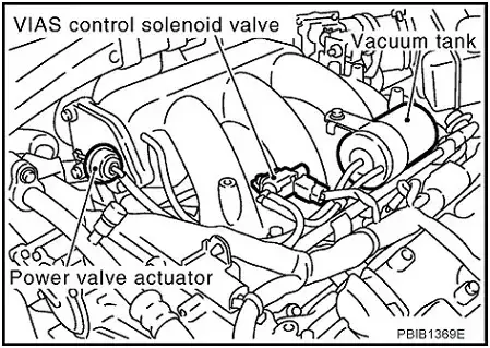
(Image credit: Nissan Murano Forum)
The P1800 code is something that many Nissan car owners often come across, especially those who have Maxima, Murano, Quest, and Altima vehicles. These particular models tend to have more frequent reports of experiencing the P1800 code.
How Serious Is The Nissan P1800 Code?
When it comes to the severity of the P1800 code, it is typically considered a moderate issue. While the code itself may not cause immediate breakdown or drivability problems, it should not be ignored.
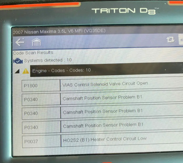
(Image Credit: Reddit)
It’s generally safe to continue to drive with the code in the short term. However, you should get it addressed as soon as you can. Driving with the P1800 code present for an extended time may lead to decreased engine performance, especially during high-demand situations where additional power is required.
Common Warning Signs Of P1800 Nissan Code
Experiencing the P1800 code in your Nissan vehicle can result in several noticeable symptoms, including:
- Check Engine Light (CEL) or Service Engine Soon (SES) light illuminated
- Unstable motor operation or sluggish engine performance
- Lack of throttle response
- Hesitation, kick, or jerk felt when shifting gears
- Acceleration issues when switching from Drive to Reverse
Read more: Nissan Faults Codes (PDF Free Download)
What Triggers The P1800 Nissan Code?
The P1800 code in Nissan vehicles can have various underlying causes, including:
- Issues with the solenoid valve circuit wiring or connectors (open or shorted)
- Malfunctioning VIAS control solenoid valve
Keep in mind that the above are just main causes. Additionally, some Nissan owners have shared that a faulty Mass Air Flow (MAF) sensor can sometimes contribute to triggering the P1800 code. While it’s not very common, it’s good to keep this possibility in mind when diagnosing the issue.
P1800 Nissan Diagnosis & Repair: Step-by-Step Guide For Resolution
The most common approach to address the P1800 code is inspecting and potentially cleaning or replacing the VIAS control solenoid valve. Alternative solutions include replacing the MAF sensor or installing a block-off plate, which is an aftermarket part used to bypass or block the VIAS system.
However, it is essential to note that these solutions may only be applicable or effective for some vehicles or situations. You should consult a professional mechanic or refer to the vehicle’s service manual for guidance specific to your car before proceeding with any alternative solutions.
In this section, we’ll guide you through inspecting and repairing the VIAS valve to solve the P1800 Nissan code. Let’s dive in.
Essential Tools And Parts
- OBD-II scanner or code reader
- Basic hand tools (such as wrenches and sockets)
- Electrical cleaner
- VIAS control solenoid valve
Step-by-Step Procedure
Step 1: Retrieve diagnostic trouble codes (DTCs)
Connect an OBD-II scanner to retrieve the P1800 code and any additional codes stored in the vehicle’s computer system.
Step 2: Locate the VIAS control solenoid valve
The valve in Nissan vehicles is often easy to access. It is typically situated on or near the intake manifold. Refer to the service manual for precise location details.
Step 3: Inspect and clean the valve
Check the valve and its electrical connections. Clean if dirty, repair faulty connections, and secure the wiring harness.
Step 4: Test the resistance
Test the solenoid valve’s resistance using a multimeter. Compare with manufacturer specifications.
Step 5: Replace the solenoid valve
If the solenoid valve is faulty, replace it with a new one following the manufacturer’s instructions. Disconnect electrical connectors, remove mounting bolts, and take note of the valve’s orientation during removal.
Then, install the new valve, ensuring proper alignment, secure fastening, and connection of electrical connectors.
Step 6: Clear codes and test drive
Clear the codes using the OBD-II scanner and test drive the vehicle to verify if the code reappears.
Note: Consult a professional mechanic or refer to the vehicle’s service manual if you have any uncertainties or encounter difficulties during the process.
DIY Repair Level And Estimated Costs
Diagnosing and replacing the VIAS control solenoid valve can be a moderately challenging DIY repair. It requires basic automotive knowledge and the ability to use hand tools. Cleaning or replacing the MAF sensor is generally more accessible for DIY enthusiasts.
For estimated costs, here is a breakdown of the main repair tasks:
| Repair Task | Cost Range |
| Diagnostic fee | $50 – $150 |
| Wiring repair | $50 – $200 |
| VIAS control solenoid valve replacement | $50 – $300 (part and labor) |
While DIY repairs can save money, consulting with an expert or mechanic is crucial if you’re uncertain about the diagnosis or repair process. They can provide guidance and ensure proper resolution of the P1800 code in your Nissan vehicle.
Wrapping Up
In conclusion, addressing the P1800 code in your Nissan vehicle is crucial to keep your engine running smoothly. Whether you decide to tackle the repairs yourself or get expert help, following a step-by-step approach is important.
If you have any questions or need further assistance, don’t hesitate to reach out.
Also, check out our user-friendly OBD Code Lookup for diagnosing and understanding other codes.
Share your experiences with the P1800 code in your Nissan vehicle in the comments below!
Best of luck with your Nissan!
Reference Sources
- JustAnswer, DTC P1800 (PDF File).
- Nialtima.com, Nissan Altima 2007-2012 Service Manual: P1800.
P2096 – Post Catalyst Fuel Trim System Too Lean
P2096 – Post Catalyst Fuel Trim System Too Lean
P2096 is one of the many codes related to the engine’s air to fuel ratio. In the case of the P2096 OBD2 code, it indicates a lean condition downstream of the catalytic converter. Many different factors can cause this, from vacuum leaks to a damaged fuel pump.
The good news is, most of these components have their own trouble codes, which will also trigger when there is a problem. This makes your OBD2 scanner an essential tool in your arsenal when it comes to clearing a P2096 trouble code.
P2096 Code Definition (Generic): Post Catalyst Fuel Trim System Too Lean Bank 1
P2096 BMW Code Definition: Index 150
P2096 Dodge Code Definition: Downstream Fuel Trim System 1 Lean
P2096 Ford Code Definition: Post Catalyst Fuel Trim System Too Lean Bank 1
P2096 Jeep Code Definition: Downstream Fuel Trim System 1 Lean
P2096 Nissan Code Definition: Post Catalyst Fuel Trim System Bank 1

What Does P2096 Mean?
The right mix of air and fuel is crucial to maintaining your engine’s proper operation. And it’s a particular ratio: 14.7 parts air to each 1 part fuel. The oxygen sensors measure the air to fuel ratio in your exhaust stream to verify it’s in keeping with these specifications.
Most modern engines use two oxygen sensors.
- The one upstream of the catalytic converter is labeled oxygen sensor 1.
- A second sensor is positioned downstream of the catalytic converter and is referred to as sensor 2.
Usually, oxygen sensor 1 will report a higher fuel ratio than oxygen sensor 2.
When the air ratio to fuel is too high, it’s a lean condition. Depending on how lean the engine is running, this could reduce your engine performance and lead to misfires. Because of this, the powertrain control module (PCM) or engine control module (ECM) regularly monitors and adjusts the air to fuel ratio throughout the drive cycle.
Fuel trim is the term for these adjustments made by your engine’s computer. When the PCM or ECM detects that more fuel needs adding to the mix, it will trigger the P0505 and make the necessary adjustments.
There are two main reasons your vehicle could run lean. Either too much air is being introduced to the system or not enough fuel is being released. Identifying which is the case is critical for an accurate diagnosis.
What Are The Symptoms Of The P2096 Code?
Depending on the source of the P2096 trouble code, you may not experience any drivability symptoms. The code’s most common symptoms include:
- Activation of the check engine light
- Rough idle
- Knocking from the engine
- Engine misfires
- Difficulty accelerating
- Reduced gas mileage
- Reduced engine performance
- Catalytic converter glowing red
- Sulfur or rotting egg smell in the exhaust
What Are The Causes Of P2096?
- Vacuum or exhaust leaks
- Damaged gaskets and o-rings in the exhaust system
- Cracked or rusty exhaust manifold
- Clogged filter
- Clogged catalytic converter
- Faulty or damaged fuel pumps
- Damaged fuel pressure regulator
- Defective or damaged oxygen sensor or oxygen sensor circuit
- Defective or damaged mass airflow sensor
How Serious Is The P2096 Code?
The P2096 trouble code is of moderate severity. A vehicle registering this code can often continue to drive safely in the short term. However, misfires and other issues caused by an incorrect air to fuel ratio can lead to lasting engine damage. You should identify and repair the problem as soon as possible.
How To Diagnose And Fix The P2096 Code
Tools you’ll need:
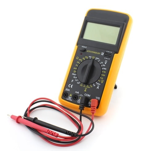
- Check for any technical service bulletins related to this code for your vehicle. Many makes and models have a history of issues with a specific component. Follow any vehicle-specific repair steps recommended before beginning with the general diagnosis below.
- Use an OBD2 scanner to check for other trouble codes. These can help to guide your diagnosis. Codes related to the catalytic converter, such as P0420, suggest this is the faulty component. You may also see codes related to the oxygen sensors or mass airflow sensor (especially P0100) if they are failing. Address these codes first, then clear the codes and test drive your vehicle to see if the P2096 code returns.
- While the car is running, look beneath it for the catalytic converter. If it is glowing red, this likely means it’s clogged. Try taking a hard drive, pushing your vehicle over 50 MPH (miles per hour) for at least 15 minutes at a time, then slowing down quickly. Stop and recheck your catalytic converter. If it’s still red, remove and clear it.
- Visually inspect the vacuum lines and exhaust system. Check for any cracks, damage, or visible leaks and ensure all the ends are secured. Also, keep your eye out for cracks in the gaskets, missing gaskets, or rust holes. Replace or tighten components as necessary.
- Inspect the electrical connectors for the oxygen sensors and mass airflow sensors. Also, check the wiring for damage or disconnects. Jeeps and Chryslers are especially known for using electrical connectors that wear easily, which is often the source of the P2096 code in these vehicles.
- Test the downstream oxygen sensor with a digital multimeter. If it’s faulty or shorted, replace it.
Common Mistakes To Avoid While Diagnosing The P2096 Code
Don’t forget to clear the codes before starting your diagnosis to verify that a problem exists. Since this code triggers concurrently with the ECM or PCM’s fuel trim adjustments, the lean condition may no longer be an issue in some cases.
Tips To Avoid P2096 In The Future
The connectors, wires, and hoses in your engine are all susceptible to damage if not cared for properly. You should check them as part of your regular maintenance routine. Ensure no hoses or wires are touching engine components that could cause damage. If you notice rust or corrosion damage, identify and fix the source of the moisture. These small steps can help extend the life of these components
Read more: P0505 Code: Meaning, Symptoms, Causes, Diagnostics, And Fixes
P0302 Code: Cylinder 2 Misfire Detected
P0302 Code: Cylinder 2 Misfire Detected
Engine misfires reduce your engine’s power and can lead to serious complications. The P0302 OBD2 code triggers when cylinder 2 experiences misfires. Knowing which cylinder is having problems is very beneficial when you’re preparing to make repairs.
The P0302 trouble code is potentially quite serious and warrants repair the moment it appears. Read on below to learn more about what this code means and how to diagnose it.
P0302 Code Definition
P0302 Code Definition (Generic): Cylinder 2 Misfire Detected
P0302 BMW: “Misfiring Of Cylinder 2, Damages TWC”
P0302 Dodge: Cylinder 2 Misfire Detected
P0302 Ford Focus: Cylinder #2 Misfire Detected
P0302 Honda: Cylinder 2 Misfire Detected
P0302 Jeep: Cylinder 2 Misfire
P0302 Nissan: Cylinder #2 Misfire Detected
P0302 Toyota: Cylinder 2 Misfire Detected
P0302 VW: Cylinder 2 Misfire
What Does P0302 Mean?
The P0302 OBD2 trouble code triggers when there’s a misfire in your engine. You’ll likely see it along with P0300, which is a more general misfire-related code. P0302 points you to the specific cylinder that’s misfiring: cylinder 2. If you’re not sure which cylinder this is, check your vehicle’s repair manual.
The cylinders are what give your engine its power. Each is topped with a spark plug that ignites the air/fuel mixture in your engine. When your vehicle’s running correctly, each cylinder fires in sequence, providing continuous power to the crankshaft.
If the crankshaft’s RPM changes by more than 2% because of a misfire in cylinder 2, the P0302 trouble code is triggered. You will likely notice significant driving issues if these misfires persist.
What Are The Symptoms Of The P0302 Code?
Engine misfires usually cause significant drivability issues. These symptoms often include:
- Activation of the check engine light. If the light is solid, the change in the crankshaft’s RPM is between 2% and 10%. A blinking or flashing check engine light indicates a change of more than 10%.
- Rough driving. Your car may especially jerk or hesitate when you accelerate. It may also shake or run roughly in other conditions, such as while idling.
- Difficulty starting or failure to start
- Stalling while idling
- Smell of fuel from the exhaust
- Reduced engine power
- Reduced fuel economy
What Are The Causes Of P0302?
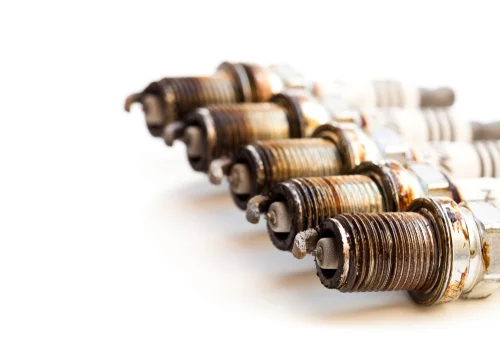
The most common causes of a cylinder 2 misfire are:
- Cylinder 2 spark plug is faulty or worn
- Damaged or faulty coils
- Damaged or faulty wires around the spark plugs
- Failed distributor
- Faulty fuel injector
There are other issues that can lead to misfires, including:
- Low fuel pressure
- Leaks in the vacuum system
- Clogged EGR valves, tubes, or ports
- Leaking head gasket
- Malfunction in the fuel system (fuel pump, fuel filter, etc.)
- Defective sensor (camshaft sensor, crankshaft sensor, MAF sensor, oxygen sensor, etc.)
- Fuel quality too low for the system
- Faulty distributor cap or rotor button (if applicable)

How Serious Is The P0302 Code?
The P0302 OBD2 code is very severe. You should not drive your car until you’ve identified the source of the problem. Misfires can cause long-term damage to your catalytic converter and ignition system. The erratic driving they cause also makes your vehicle unsafe to operate.
How To Diagnose The P0302 Code
Tools you’ll need:
- OBD2 scan tool
- Screwdriver and socket set
- Digital multimeter
- Fuel pressure gauge
- Compression tester
- Leakdown tester
- Scan your system for other codes using the OBD2 scan tool. If any other codes come up other than P0300 and other misfire-related codes, fix those first. The other code may be pointing you to the root cause of the misfire.
- Check the wires around the spark plugs to make sure none are loose or damaged. Be sure to also check for loose engine ground wires. Replace or tighten as necessary.
- If your vehicle has individual coil packs in the cylinders, swap the coil from cylinder 2 with the one in cylinder 4. Clear the codes and test drive your car. If the misfire moves to cylinder 4, replace the coil pack.
- Visually inspect the cylinder 4 spark plug with a new spark plug on-hand for comparison. If the plug looks dirty or has carbon build-up, remove and clean it.
- Test the resistance of the spark plug wires using a multimeter. The typical resistance is between 10,000 and 15,000 ohms. You can find the specific resistance in your vehicle’s manual. If the resistance is higher, replace the wire.
- Use a multimeter to test the ignition coils. Remove the coil and touch the leads of the multimeter to both the primary and secondary ignition circuits. The primary ignition circuit should read between .4 and 2 ohms, and the secondary between 6,000 and 10,000 ohms. A 0 reading on either indicates an internal short.
- Test your fuel system using a fuel pressure gauge. The correct readings for your engine should be listed in your manual.
- Use a multimeter to check the fuel injectors. First, unplug the injector from the engine, then use the multimeter leads to probe the terminals. Check your vehicle manual for the correct resistance.
- Perform a leak down test and an engine compression test. Mechanical problems can often lead to engine misfires. Common things to look for are a burned valve, a broken piston ring or valve spring, a worn valve guide, or skipped teeth on the timing chain.
Common Mistakes To Avoid While Diagnosing The P0302 Code
It’s easy to overlook small issues like a broken wire or a loose electrical connection. Be thorough in the inspection of your engine. If you’re lucky, you’ll only need to make a minor repair.
What Should You Do To Fix The Code P0302?
If you’re not experiencing any drivability issues, clear the trouble code. A single misfire may not be cause for significant concern. Take a test drive to see if the code comes back. If it does, continue with the steps below.
- Replace any damaged wires, connectors, or tabs found in your inspection.
- Replace any components that failed the diagnostic tests above.
- Clean the fuel injectors using a fuel injector cleaning kit. You can find these at any auto parts store.
- If the problem persists, test your engine’s sensors, including the crankshaft sensor, camshaft sensor, oxygen sensors, and MAF sensor. Replace or clean them as necessary.
Tips To Avoid P0302 In The Future
Replacing your ignition system’s minor components as part of your regular maintenance can prevent problems before they occur. Verify the recommended lifespan of your spark plugs, rotor, and distributor cap. Replace them before they’ve exceeded this lifespan.
Read more: P0325 Code: Meaning, Symptoms, Causes, Diagnostics, and Fixes
P0122 – Throttle/Pedal Position Sensor/Switch “A” Circuit Low
P0122 – Throttle/Pedal Position Sensor/Switch “A” Circuit Low
The P0122 code triggers when the “A” circuit on your vehicle’s throttle position sensor gives too low of an input voltage.
This sensor is used by your engine control module to track the position of the throttle.
When it fails, your engine will activate the failsafe mode.
This makes any TPS code very important to clear as soon as possible.
For as serious as this code can be, the repairs are often relatively inexpensive and easy to make, even for a home mechanic.
While you may need to replace the sensor, it may also only be a problem with the wiring around it.
Read on below to learn more about why this code triggers and how you can resolve the problem.
P0122 Code Definition
P0122 Code Definition (Generic): Throttle Position Sensor/Switch A Circuit Low Input
P0122 Dodge Code Definition: Throttle/Pedal Position Sensor/Switch “A” Circuit Low
P0122 Ford Code Definition: (TP) sensor circuit low input
P0122 Jeep Code Definition: Throttle/Pedal Position Sensor/Switch “A” Circuit Low
What Does P0122 Mean?
The throttle position sensor (TPS) monitors the movement of your throttle. When the throttle opens, it generates a voltage. The more open the throttle, the higher the voltage should be. This data is sent from the TPS to the engine control module (ECM), which monitors the overall engine performance.
The TPS has two circuits, labeled “A” and “B”. Each of these has a certain voltage range that it should report. When the “A” circuit output drops below the minimum voltage threshold, the P0122 trouble code is triggered.
Your exact TPS “A” circuit voltage range will vary depending on your vehicle’s manufacturer. Typically the lower limit should be around .2 volts, but you can find the specific voltage in your car’s manual. You’ll likely see this code appear alongside P0121 if the “B” circuit is operating correctly.
What Are The Symptoms Of The P0122 Code?
The symptoms of P0122 can vary. It will activate your engine’s failsafe mode in most vehicles, cutting power to the actuator and reducing how far the throttle can open. This will limit your maximum speed and overall engine performance.
Other common symptoms include:
- Activation of the check engine light
- Rough idling
- Low or high idling
- Stalls
- Reduced acceleration or failure to accelerate
- Engine surges
What Are The Causes Of P0122?
- Incorrectly mounted TPS
- Faulty or damaged wiring on the TPS
- Short in the TPS ground
- Faulty TPS
- Damaged or faulty ECM
How Serious Is The P0122 Code?
The P0122 trouble code is serious. When your vehicle’s failsafe mode activates, you will have a lot of trouble accelerating and may experience frequent stalls. This makes your car unsafe to drive, as well as raising the potential risk for internal engine damage. You should avoid driving your vehicle until you’ve cleared this code.
How To Diagnose And Fix The P0122 Code
While P0122 is a generic powertrain code, the exact fixes may vary depending on your car’s make, model, and manufacturer. Check your manual for any recommended repair steps. You may also find technical service bulletins that have been released for your vehicle, suggesting specific repairs. Follow these first before proceeding with the generic diagnosis below.
Tools You’ll Need:
Method:
- Scan your vehicle with an OBD2 scan tool to see if any other codes are present. You may see other trouble codes related to the TPS (P0120-P0124). Also, read the freeze frame data to check what conditions were present when the code activated.
- Check the throttle position sensor to make sure it’s installed correctly. Very often, the P0122 code triggers if you don’t rotate the TPS when you’re installing it. The inside tab of the TPS must contact the throttle body’s rotating pins to operate.
- Once you’ve correctly installed the TPS, verify all the connections are secure. Clear all codes using your OBD2 scanner and test drive your vehicle. Very often, this will fix the issue. If it doesn’t, continue with the diagnosis.
- Visually inspect all the wiring around the TPS. Replace any that are damaged or corroded. Also, check the connectors to make sure they’re not damaged.
- Compare the “A” and “B” circuit readings from your throttle position sensor. If they don’t match, check your vehicle manual for specific steps and tests to follow.
- Use a multimeter to check the voltage of the TPS. You can find the correct voltage in your vehicle’s manual. If it is too low, replace the TPS.
- Test the ground for the throttle position sensor using a digital multimeter; if the reading indicates an open or short, repair or replace it.
In some cases, the P0122 trouble code is an intermittent problem. You may find the code clears initially, only to recur a few days or weeks down the line. In these cases, drivers often don’t experience any symptoms aside from those associated with the failsafe mode. This typically indicates a wiring issue. Re-check all the wiring around the TPS. If you can’t identify the specific problem, you may want to replace the entire harness.
Common Mistakes To Avoid While Diagnosing The P0122 Code
Many inexperienced mechanics simply replace the throttle position sensor before they’ve verified this is the problem. Make sure you thoroughly inspect all the wires and connectors around the sensor before you replace any components. This will ensure you fix the entire problem.
Tips To Avoid P0122 In The Future
This code most commonly triggers after the throttle position sensor is replaced or adjusted due to incorrect installation. Make sure you’re careful to install any new components correctly. This includes checking that all wires and connections are secure. The wires of the throttle position sensor can be damaged by rubbing against the wiring harness. Double-check the placement of the wires every time you install, replace, or adjust the sensor. Damaged wires are one of the main causes of TPS trouble codes, including P0122.
Read more: P0017 Code: Meaning, Symptoms, Causes, Diagnostics, and Fixes
P0171: System Too Lean (Bank 1)
P0171: System Too Lean (Bank 1)
The P0171 code generally tells you too much air is getting into your engine. While this fault code isn’t severe on its own, it can lead to further damage that is more serious.
Let’s take a quick look at a brief of the P0171 code below.
- P0171 Definition: System Too Lean (Bank 1)
- Code type: Generic – P0171 indicates the same problem whether you’re having a Chevy, Ford, or Toyota, etc.
- Can I drive with the P0171 code? Yes, but you should not drive your vehicle for a long time.
- Is it easy to fix? Intermediate level.
- Cost: $10 – $200 (common)
To help you fully understand the P0171 code and find the right fix, I divided the article into 4 parts.
Click on the images below to jump right into it!
What Does The P0171 Code Mean?
Diagnostic trouble code (DTC) P0171 stands for “System Too Lean” (Bank 1). The air-fuel mixture with too much air and little gasoline could trigger this trouble code.
Lean Mixture = Too much air, not enough fuel
Further Explanation
In normal conditions, the combustion engine operates effectively with an air-fuel ratio of 14.7:1. Specifically, every 14.7 grams of air combines with 1 gram of fuel.
In case Bank 1 receives too much air or/and too little fuel, the engine would be running lean. A vacuum leak or faulty fuel system can be the problem for this.
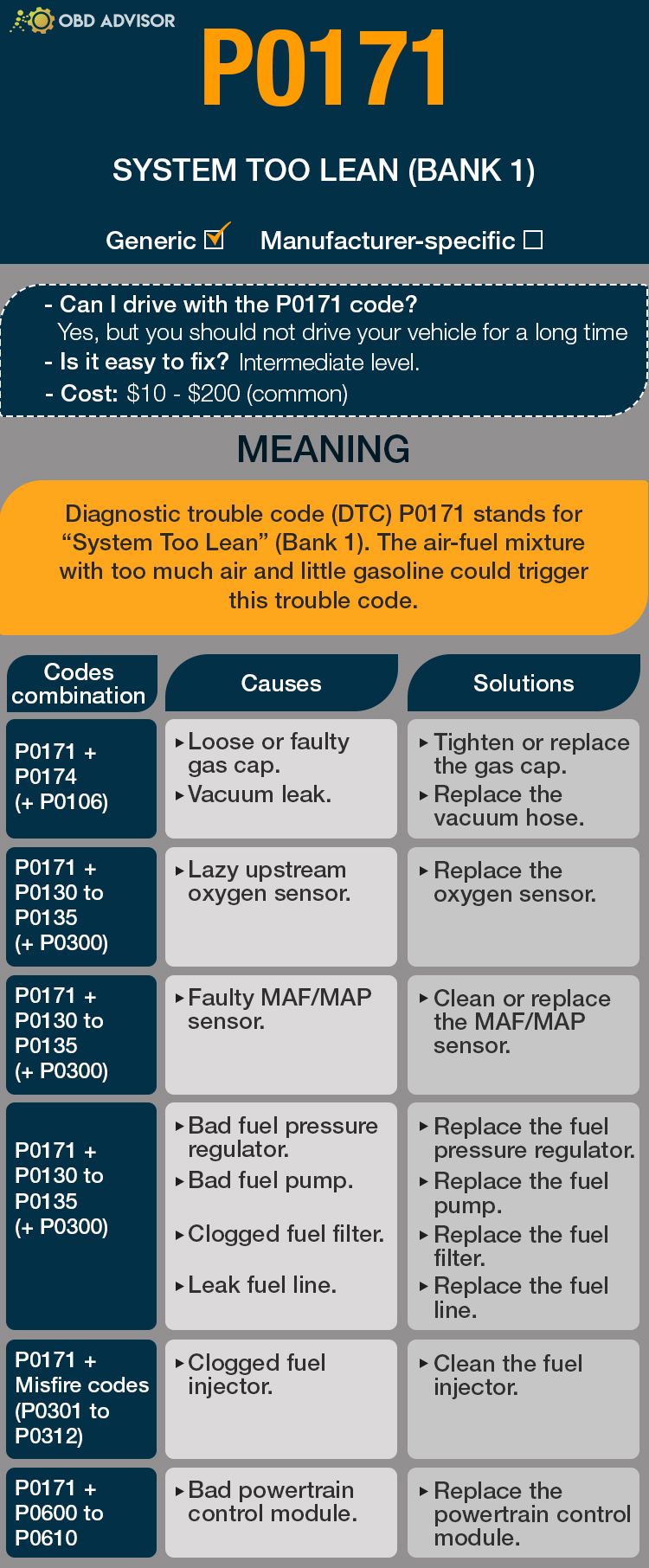
P0171 Causes Identification: Quick View
Usually, your scan tool throws P0171 with other codes.
This could be a bit challenging to determine the cause. So, I compiled this table to make it easier for you to diagnose the problems and fix them.
| Codes Combination | Causes | Solutions |
|---|---|---|
| P0171 + P0174 (+P0106) | Loose or faulty gas cap. Vacuum leak. | Tighten or replace the gas cap. Fix the vacuum leak. |
| P0171 + P0130 to P0135 (+P0300) | Lazy upstream oxygen sensor. | Replace the oxygen sensor. |
| P0171 + P0100 to P0104 | Faulty MAF/MAP sensor. | Clean or replace the MAF/MAP sensor. |
| P0171 + P0174 (+P0087/P0089) | Bad fuel pressure regulator. Bad fuel pump. Clogged fuel filter. Leak fuel line. | Replace the fuel pressure regulator. Replace the fuel pump. Replace the fuel filter. Replace the fuel line. |
| P0171 + Misfire codes (P0301 to P0312) | Clogged fuel injector. | Clean the fuel injector. |
| P0171 + P0600 to P0610 | Bad powertrain control module. | Replace the powertrain control module. |
Note: The causes for each code combination are the most common ones. There can be some uncommon issues hidden under those codes
P0171: Causes, Symptoms, and How To Fix
Did you find your problem? To further ensure that you actually find the right one, you need to match your car’s symptoms with the cause.
If you don’t want to be a part changer, read on and understand your problem from the inside!
Cause #1: Loose Or Faulty Gas Cap
Checking the gas cap is the very first thing you need to do.
A loose or faulty gas cap will mess up the fuel system, leading to check engine light on and the lean conditions codes popping up.
Make sure the gas cap is not the problem, and you can move on to further diagnosis.
Cause #2: Vacuum Leak
A leak in the air intake system allows air to enter the combustion chamber without the car computer knowing that.
As a result, the amount of fuel that needs to be injected into the engine could be miscalculated by the PCM.
This leads to too much air in the air-fuel mixture.
Try to find and fix it with this video.
Symptoms of vacuum leak:
- P0171 arises with P0174 (sometimes with P0106)
- Hissing sound
- Check Engine Light on
- Rough idle
- Car stalling
- Long-term fuel trim (LTFT) > 10% (check-in “Live data” category)
A smoke test to locate the leak is the first thing you need to do.
Cracked hoses or loosened clamps are usually the reasons for vacuum leaks. In those cases, replacing the hose or tightening the clamp should fix the problem.
Cause #3: Lazy Upstream Oxygen Sensor
The upstream oxygen sensor helps adjust the air and fuel ratio in the engine to its PCM.
The oxygen sensor may be “lazy” because it’s old or dirty, leading to an incorrect air-fuel ratio.
Symptoms of a bad upstream O2 sensor:
- A combination between P0171 and faulty oxygen sensor codes (P0130 to P0135) or in some rare cases, P0300 appears
- Check engine light on
- Bad fuel economy
To make sure your upstream O2 sensor is bad, check the voltage chart on your bank 1 upstream sensor (using the “Live Data” function in your scan tool).
If the value is constantly higher than 0.45v, that’s the wrong data telling the PCM to reduce the fuel (while it’s not supposed to).
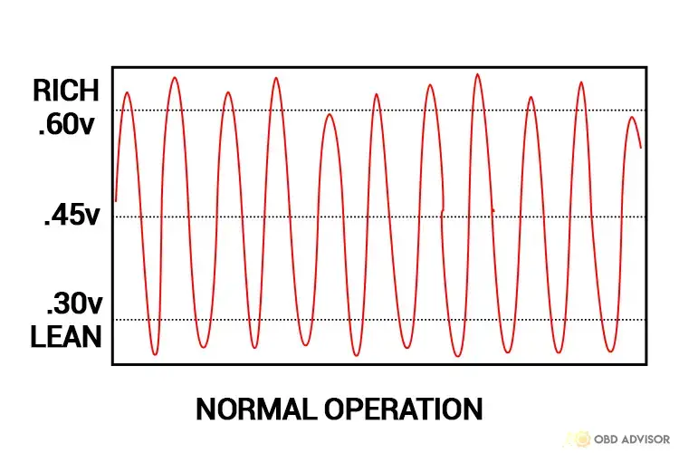
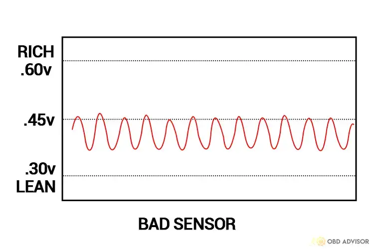
In this case, replace the O2 sensor.
Here’s how you can do it.
Cause #4: Faulty MAF/MAP Sensor
The PCM uses the Mass Airflow (MAF)/ Manifold Absolute Pressure (MAP) data to adjust the air-fuel ratio.
Therefore, when the MAF/ MAP sensor fails, the ratio is off. Then, the combination between P0171 and P0100 to P0104 will appear.
Symptoms of a faulty MAF/ MAP sensor:
- P0171 and faulty MAF/ MAP sensor codes (P0100 to P0104) activate
- Check engine light on
- Engine stalling, rough idle, misfires
- Bad fuel economy
Clean or replace your MAF/ MAP sensor when you find out it has the issue.
Installing the new MAF/ MAP sensor is straightforward so you can do it by yourself.
Watch this video to know how to replace the MAF sensor.
Cause #5: Fuel Pressure Too Low
The fuel requires a certain amount of pressure to get into the engine (55psi as common). When the fuel pressure gets low, less fuel is injected into the combustion chamber.
This problem always leads to lean conditions in both bank 1 and bank 2. Therefore, you will get P0171 and P0174 at the same time.
There are several reasons for low fuel pressure:
- Bad fuel pump: once the pump is defective, it can not create enough pressure for the whole fuel system.
- Clogged fuel filter: limit fuel flow in the system
- Bad fuel pressure regulator (FPR): if this component goes faulty, the fuel goes back to the fuel tank without any obstacles, leading to the fuel pressure decreasing.
- Leak fuel line: if there is a fuel leak in the fuel line, you’ll start smelling a strong fuel odor, or your car may experience a stall because of a fuel shortage.
Symptoms of bad fuel pressure:
- A combination between P0171 and P0174 (sometimes P0087/P0089) appears
- Hard starting
- Poor performance
- Engine stalling
- Poor throttle response
- Fuel smell (in case of external leak fuel line)
Several things could be causing the low fuel pressure. So you have to diagnose first to detect which is the cause of this problem. Then find the solution for each cause.
Here are the solutions to fix the poor fuel pressure: replace the fuel pressure regulator, the fuel pump, the fuel filter, or the fuel line.
Cause #6: Clogged Fuel Injector
If your fuel injectors are clogged, they will prevent fuel from flowing through them. Then, the amount of fuel in the engine will reduce.
You need to maintain the fuel injectors regularly. If not, the fuel injectors can become clogged, resulting in the P0171 code being triggered with misfire codes (P0301 to P0312).
Therefore, you need to look out for signs of a bad fuel injector and fix it by cleaning the fuel injector.
Symptoms of clogged fuel injector:
- P0171 combines with misfire codes (P0301 to P0312)
- Misfires
- Rough idle and engine stalls
- Bad fuel economy
Here’s the way to clean the clogged fuel injector.
Cause #7: Bad Powertrain Control Module
The PCM has the function of calculating the exact amount of fuel added to the air-fuel ratio when air enters the engine. The engine computer uses data from different engine sensors to adjust the air-fuel ratio.
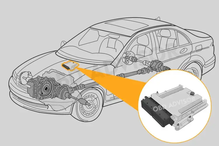
So when the PCM fails, it won’t be able to calculate the ratio correctly, leading to the P0171 code being activated with P0600 to P0610.
Symptoms of a bad PCM:
- The combination between P0171 and P0600 to P0610 appears
- Check engine light on
- Car won’t start
- Bad fuel economy
- Emissions test failure
- Engine stalls
The faulty PCM is a rare situation causing the P0171. Fixing the PCM is expensive, complicated, and we don’t recommend replacing it yourself.
How Much Does It Cost To Fix The Code P0171?
The common fixing cost of the P0171 code can be $10 or $200, based on the components that need to be replaced and the labor cost in case you cannot DIY.
A vacuum leak is one of the common causes of the P0171, and the cost to replace it is $10 – $200.
The cost to replace an oxygen sensor is around $20 – $130 when changing it yourself or $70 – $250, including the component and labor costs.
The estimated repair cost of P0171
| Solutions | Estimated Cost |
|---|---|
| Replace the gas cap | DIY: $10 – $20 Repair shop: $25 – $40 |
| Fix the vacuum leak | DIY: $10 – $200 Repair shop: $150 – $1,000 |
| Replace the oxygen sensor | DIY: $20 – $130 Repair shop: $70 – $250 |
| Clean the MAF/MAP sensor | DIY: $15 Repair shop: $50 – $100 |
| Replace the MAF/MAP sensor | DIY: $30 – $300 Repair shop: $80 – $380 |
| Replace the fuel pressure regulator | DIY: $50 – $200 Repair shop: $150 – $350 |
| Replace the fuel pump | DIY: $95 – $850 Repair shop: $220 – $1,100 |
| Replace the fuel filter | DIY: $10 – $70 Repair shop: $50 – $175 |
| Replace the fuel line | DIY: $10 – $150 Repair shop: $200 – $500 |
| Clean the fuel injector | DIY: $10 Repair shop: $60 to $100 |
| Replace the PCM | DIY: not recommend Repair shop: $1,000 – $3,000 |
Note: The data in this table is collected in June 2022. The price depends on many factors, such as your car’s make and year, mechanic’s fee, etc.
You Ask, I Answer
If the P0171 code appears, don’t ignore it. Because there would be some severe damage that your vehicle is likely to incur, including reduced gas mileage, loss of performance, or struggling start.
After reading this article, I hope it helps you to save some money from mechanics.
Any other questions about P0171? Don’t hesitate to leave a comment below, I’ll answer them all.
If you have had the code and fixed it before, share your story and you’ll help lots of folks having this problem.
See ya!
Read more: The 9 Best OBD2 Scanners for 2024: The Only Review You Need
P0131 – O2 Sensor Circuit Low Voltage
P0131 – O2 Sensor Circuit Low Voltage
The P0131 code triggers when the voltage output of your upstream bank 1 oxygen sensor is too low. Your engine computer uses this sensor to control the air to fuel ratio. Since maintaining the correct rate is key to proper engine operation, you should note when this trouble code activates.
Fixing the P0131 OBD2 code may require replacing the oxygen sensor, but damaged wires and hoses can also cause it. A thorough diagnosis is essential to find and address the true root of the problem. Read on below for more details about this code and what to do if it’s active.
P0131 Code Definition (Generic)
Oxygen O2 sensor circuit low voltage (Bank 1, Sensor 1)
What Does P0131 Mean?
The oxygen sensors in your engine are how the power control module (PCM) or engine control module (ECM) monitors the air-to-fuel ratio in your exhaust. Comparing this data with the air outside the engine can determine when to inject more fuel or open the system to allow more air to enter.
There are two oxygen sensors in the vehicle. The upstream oxygen sensor, called sensor 1, is positioned before the catalytic converter. It is different from the downstream oxygen sensor, called sensor 2, which measures the air coming out of the catalytic converter.
The P0131 trouble code triggers when the ECM or PCM detects a low voltage from the upstream oxygen sensor. Usually, the voltage must be below the threshold for a certain length of time before the code will trigger. Typically this is two minutes, but it can vary depending on your vehicle.
While P0131 is a generic trouble code, applying to all OBD2 vehicles, the specific fixes can vary depending on your make and model. It’s always a good idea to consult your manual and check for any technical service bulletins before beginning your diagnosis and repair.
Other diagnostic trouble codes related to the oxygen sensors include P0136 and P0137. These codes also warn of a low oxygen sensor voltage, although for a different sensor.
What Are The Symptoms Of The P0131 Code?
In some cases, there are no drivability issues with the P0131 trouble code. This case is relatively rare, however. Typically, you’ll experience one or more of the following symptoms:
- Activation of the check engine light
- Smoke in the exhaust
- Bad smell from the exhaust
- Rough running engine
- Reduced fuel economy
- Stalling engine
What Are The Causes Of P0131?
- Faulty or damaged oxygen sensor heating circuit
- Defective oxygen sensor
- Faulty or damaged wiring around the oxygen sensor
- Shorts, open, or high resistance in the oxygen sensor signal circuit
- Leaks in the vacuum system
- Fuel pressure too low or too high
- ECM or PCM software requires an update
- Faulty ECM or PCM (not as common)
How Serious Is The P0131 Code?
While the severity of the P0131 code can vary, it can be of high severity. Therefore, you should stop driving your vehicle as soon as possible and identify the root of the problem. Failure to do so could lead to more serious engine damage.
How To Diagnose And Fix The P0131 Code?
Tools you’ll need:
- Use an OBD2 scan tool to check for other trouble codes, then clear codes and test drive your vehicle to see if the code recurs. In some cases, P0131 is an intermittent problem. Especially if you haven’t experienced any drivability symptoms, the code may clear without issue.
- Read the freeze frame data for oxygen sensor 1. Pay attention to the miles per hour (MPH), revolutions per minute (RPM), and load readings. Also, read the engine temperature sensor readings and the oxygen sensor 2 readings to look for any inconsistencies.
- Visually inspect the wiring around the oxygen sensor. Replace any wires that are damaged or corroded, and check the connectors for damage, as well. Ensure all the wires are firmly connected and clear of any other engine components that could cause future damage.
- Inspect the wiring harness. Perform a wiggle test to make sure it’s not chafing or grounding.
- Check the vacuum hoses around the bank 1 upstream oxygen sensor for leaks. Make sure to feel along with hidden areas of the hoses for damaged or weak spots you can’t see. Pay close attention to the ends of the hoses, as well, making sure there’s no fraying or damage and that all hoses are secured tightly.
- Use a digital multimeter to check the voltage output of oxygen sensor 1 on bank 1. Your vehicle’s manual can tell you what the voltage reading should be. If it’s giving a null or infinite reading, you likely have an open or short in the oxygen sensor. Any variance from the designated range is a sign your oxygen sensor probably needs to be replaced.
- Check the signal wire at the PCM or ECM using the digital multimeter. Check for shorts and open circuits, and replace the connector or wire as necessary.
- If the code still doesn’t clear, you may need a software update or have a more significant electrical issue. In either case, your best option is to take your vehicle to a professional mechanic for further diagnosis.
Common Mistakes To Avoid While Diagnosing The P0131 Code
Many people replace the oxygen sensor before they search for other potential causes for the trouble code. While a defective oxygen sensor may be the issue, make sure you check for wiring issues and vacuum leaks, as well. These are equally likely to trigger the P0131 trouble code.
Tips To Avoid P0131 In The Future
Two potential causes of the P0131 trouble code are damaged or loosened wires and vacuum leaks in the exhaust system. You can avoid both through preventative maintenance. Consider applying an anti-corrosive treatment to your engine. Also, be careful when installing hoses and wires. Make sure they’re firmly connected and that they’re not rubbing engine components that could damage them.
Read more: P0135 Code: Meaning, Symptoms, Causes, Diagnostics, and Fixes
P0137: O2 Sensor Circuit Low Voltage (Bank 1 Sensor 2)
P0137: O2 Sensor Circuit Low Voltage (Bank 1 Sensor 2)
Concerned about the P0137 code popping up and not sure what it means?
Let’s give you a quick rundown of what to expect.
- P0137 Definition: Oxygen Sensor Circuit Low Voltage (Bank 1, Sensor 2.)
- Code type: Generic – P0137 indicates the same problem whether you’re having a Chevy, Toyota, or Honda, etc.
- Can I drive with the P0137 code? Yes, in the short run. However, extended driving periods may cause engine damage.
- Easy to fix? Beginner to intermediate level.
- Cost: $20 – $95 (common.)
In this article, I will go over what the code means, possible causes, solutions, and repair costs.
Let’s get started!
What Does The P0137 Code Mean?
The P0137 is triggered when the downstream O2 sensor (bank 1) voltage is lower than 0.21V for longer than 2 minutes. In many cases, it can be because your downstream O2 sensor is faulty.
Downstream oxygen sensors (located after the catalytic converter) monitor the conditions of the catalytic converter.
The more air in the exhaust gas (after passing the cats), the lower the downstream O2 sensor’s output voltage.
Because the catalytic converter already processed the exhaust gas, the oxygen level is stable. Therefore, a normal working downstream O2 sensor stays around 0.45 volts.
For some reason, the sensor may detect an abnormally high percentage of oxygen in the exhaust gas (or it thinks so.) This leads to a drop in the sensor’s voltage. And when it’s below 0.21v, P0137 is set.
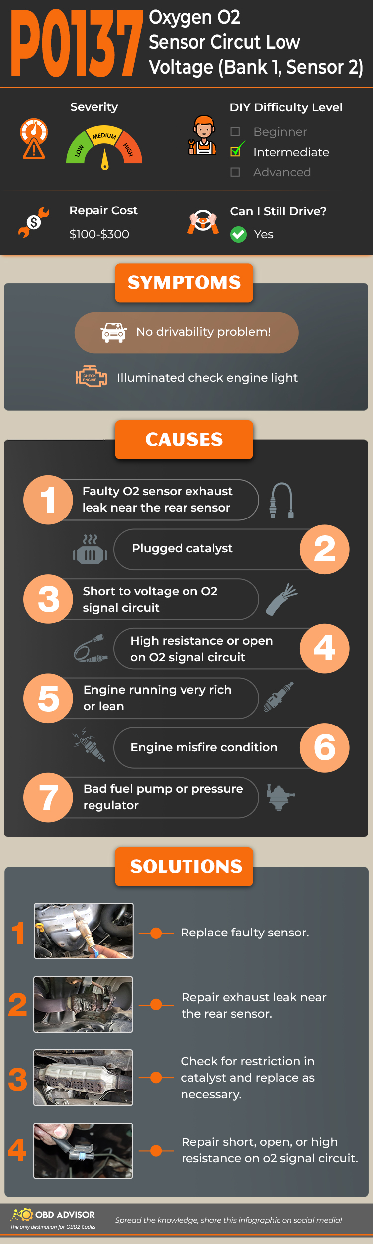
P0137 Causes Identification: Quick View
The most common cause of P0137 is a faulty downstream oxygen sensor. However, there may be other reasons.
To make the information more digestible, here is a table with the code combinations, their causes, and solutions.
| Codes combinations | Causes | Solution |
|---|---|---|
| P0137 only (no symptom); P0137 + P0420 | Bad downstream O2 sensor Faulty O2 sensor’s circuit | Replace downstream O2 sensor Fix the short or open circuit |
| P0137 + noisy exhaust | Exhaust leak near downstream O2 sensor | Apply epoxy bond (small leak)/welding (large leak) |
| P0137 + P0141 | Bad downstream O2 sensor | Replace downstream O2 sensor |
| P0137 + P0171; P0137 + P0157 | Vacuum leak Lazy upstream O2 sensor | Smoke test & Seal vacuum leak Replace upstream O2 sensor |
| P0137 + P0138 | Bad PCM | Replace PCM |
Note: The causes for each code combination are the most common ones. There can be some uncommon issues hidden under those codes.
P0137 Causes, Symptoms, and How to fix
Depending on the underlying problem, there may be different symptoms to look out for.
However, there is one common symptom that remains the same, and that is an illuminated check engine light.
Let’s explore the different causes of the P0137 error code and any unique symptoms you may experience.
Causes #1: Bad Downstream O2 Sensor
A faulty downstream O2 sensor would report false info to the PCM, which would think there is something wrong with the catalytic converter.
If this is the case, P0137 may appear alone or come with other codes like P0420, and P0141.
A bad downstream O2 sensor does not result in any symptoms with your car’s performance. This is because downstream sensors are not used to adjust the air-fuel ratio (like upstream.)
Check the O2 sensor with a multimeter. If this fails, replace it.
Causes #2: Short Or Open In Downstream O2 Sensor Wiring
Sometimes, the problem is not the downstream sensor itself.
After making sure the O2 sensor is ok, check its wiring harness for any short, high resistant, or open.
Again, this cause will not lead to any symptoms.
Causes #3: Exhaust Leak Near Downstream O2 Sensor
When the exhaust gas is pushed out of the system, it forms a pulse. The front end of the pulse has a high pressure while the negative pressure is behind.
When there is a leak, some of the gas in the front end of the pulse escapes. However, the low pressure at the end of the pulse sucks the air in.
The changes in the exhaust gases cause an inaccurate reading on the downstream O2 sensor.
The most obvious symptom of an exhaust leak is the buzz or hum sounds when the engine is running. You can rev the car intermittently to hear the sound more clearly.
After finding the leak, you would need to repair it by applying epoxy to seal a small leak or performing welding for a larger one.
Causes #4: Lean Condition (Bank 1)
If your engine is running lean (too much air), the exhaust gas will contain more oxygen than usual. When the catalytic can not handle all of this, some of the oxygen is still left in the exhaust gas after passing the cats.
As mentioned above, an abnormally high percentage of air will decrease downstream O2 sensors voltage, triggering P0137.
There are many reasons for the lean condition. However, vacuum leaks and lazy upstream O2 sensors (in this case, the bank 1 sensor) are the most common causes.
Vacuum leak symptoms:
- Hissing sounds
- Rough idle
- Often stalls when stopping
- Long-term fuel trim (ltft1)>10%
Lazy upstream O2 sensors symptom:
- The sensor’s output voltage slightly fluctuates above .45v (below image)
First, conduct a smoke test to make sure there is no leak in the intake system.
If there are no leaks, then the problem could be in the upstream O2 sensor. Replacing it with a new one should fix the issue.
Causes #5: Bad PCM (Rare)
Bad PCM is a rare case and it should be your last conclusion.
If your car throws a combination of P0137 and the P0138 (low voltage and high voltage on one downstream O2 sensor,) this can be the cause.
Depending on the make and model, the replacement costs of a PCM may vary. But it will not be cheap!
I suggest heading to a local mechanic for replacing the PCM as it’s a complicated process.
How Much Does It Cost To Fix The Code P0137?
The most common solution to the P0137 error code is replacing the downstream O2 sensor, which can cost between $20 and $95.
The table below will help break down repair costs (DIY and mechanic) according to the different solutions.
The Estimated Repair Cost Of P0137
| Solutions | Repair cost |
|---|---|
| Replace O2 sensor | DIY: $20 – $95 Mechanic: $100 – $450 |
| Repair O2 sensor circuit | DIY: $10 – $20 Mechanic: $130 – $140 |
| Repair exhaust leak | DIY: $20- $50 Mechanic: $130 – $190 |
| Replace PCM | DIY: Not recommended Mechanic: $1,000 to $3,000 |
Note: The data in this table is collected in May 2022. The actual price depends on many factors, such as your car’s make and year, mechanic’s rate, time, market price, etc.
You ask, I answer
Thank you for sticking with me to the end.
Although a P0137 fault code is not dangerous to drive, having the annoying CEL disappear with a few bucks is a no-brainer.
If you are still feeling confused or have any questions about P0137 or any other related codes, please do not hesitate to comment below. I’ll try my best to help you out.
See ya!
Read more: The 9 Best OBD2 Scanners for 2024: The Only Review You Need
P0013 – “B” Camshaft Position – Actuator Circuit/Open
P0013 – “B” Camshaft Position – Actuator Circuit/Open
The P0013 code relates to your engine’s variable valve timing (VVT) system, a crucial system found in all modern vehicles. Its primary purpose is to alter your camshaft’s speed to give you the right power your engine needs.
Your engine won’t always manifest symptoms when something goes wrong in the VVT system, but this doesn’t mean it can be taken lightly. Issues with your engine’s timing can lead to potentially significant engine damage, including damage to your ECM.
Luckily, the fix for P0013 is often a relatively easy and affordable one. Something as simple as a loose wire can be the culprit in many cases. It’s also one of the codes you’re likely to see if you’ve neglected your regular oil change.
Isolating the problem is often a relatively quick and easy process if you know the right steps to follow. Read the information below to learn more about this code and how you can fix it.
P0013 Code Definition
P0013 Code Definition (Generic): “B” Camshaft Position Actuator Circuit (Bank 1)
What Does P0013 Mean?
Modern engines don’t run at the same speed all the time. Instead, they use a variable timing system, adjusting the valve timing based on the sensors’ signals. This feature makes the engine’s operation more efficient, improves performance, and gives you better fuel efficiency.
When the engine control module (ECM) needs to adjust the camshaft’s timing, it does so through the camshaft position actuator. If the RPM (revolutions per minute) of the camshaft doesn’t change in response, the P0013 trouble code is activated.
Specifically, two main conditions will trigger the P0013 code. The first is when the ECM reduces the camshaft’s speed, but the oil control valve (OCV) output remains 100%. The second is when the ECM increases the camshaft’s speed, but the OCV output is 2% or less.
There are two circuits connected to the camshaft position (CMP) actuator. The high control circuit sends a 12-volt signal to the actuator, while the low reference circuit serves as a return circuit. Issues with either of these can lead to the activation of the P0013 code, as can wiring problems elsewhere in your timing system.
While P0013 is a generic code, it is only found in vehicles that use variable valve timing, including most vehicles made in the past decade, regardless of manufacturer. Exactly where you find the CMP actuator will vary depending on your engine, but the P0013 trouble code will always point you to bank 1. This is the side of the engine that contains cylinder 1.
What Are The Symptoms Of The P0013 Code?
The P0013 trouble code symptoms vary depending on what position the camshaft is in when the problem starts. Potential symptoms include:
- Activation of the check engine light
- Hard starts
- Reduced gas mileage
- Rough running
- Reduced engine performance
- Engine hesitation and stalls
What Are The Causes Of P0013?
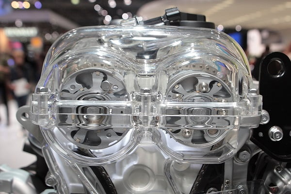
- Faulty VVT actuator
- Damaged or loose wires around the VVT system
- Open or short in the VVT system
- Faulty oil control valve
- Faulty or damaged ECM
How Serious Is The P0013 Code?
The P0013 code is of moderate severity. Driving with this trouble code active for an extended time can cause damage to your ECM. Even if you’re not experiencing significant drivability issues, you should repair the issue as soon as possible to avoid further problems.
How To Diagnose And Fix The P0013 Code
While this is a generic powertrain code, the specific fix may differ depending on your car. Check for any specific repair steps in your vehicle’s manual before beginning the generic diagnosis and repair steps below.
Tools You’ll Need:
Method:
- Scan your vehicle using an OBD2 scanner. Check the freeze frame data and the conditions present when the code was set. Also, check if any other trouble codes are present. You may see other powertrain-related codes, such as P0011, P0012, or P0020-P0022.
- Visually inspect all the wires around the VVT system. Replace any that are damaged or broken due to corrosion, and ensure that all wires are securely connected.
- Check the level and quality of your oil. Make sure the oil level is correct. Also, check the viscosity and quality of the oil. If it’s old or dirty, drain the oil, replace your oil filter, and refill your system with new oil.
- Clear the codes and test drive your vehicle, replicating the conditions under which the code was first set. If the code comes back, continue with your diagnosis.
- If the OCV is stuck open, this is often the result of an internal short. You can find out if this is the case using a digital multimeter. Measure the resistance of the terminals of the camshaft oil control valve. It should measure somewhere between 6.9 and 7.9 ohms. Your vehicle’s manual will tell you the specific reading. If they don’t match, replace the OCV.
- Remove the connectors on the oil control valve. Use a multimeter to test the wires. If you get a null or infinite reading, there is an open circuit or a short. Replace the wire.
- If the code still doesn’t clear, you may have a more serious electrical problem. Take your vehicle to a mechanic for further diagnosis.
Common Mistakes To Avoid While Diagnosing The P0013 Code
Many mechanics fail to do a visual inspection of the VVT system, assuming the problem is with the valve or circuit. Make sure you conduct a thorough diagnosis before replacing any components. The issue might be a simple and affordable one to repair.
Tips To Avoid P0013 In The Future
Preventative maintenance is the best way to stave off the P0013 trouble code. Make sure your oil is always filled to the proper level and changed when needed. Visually inspecting the wires of your system for frays and loose connections can also prevent P0013 and other trouble codes related to the variable valve timing system.
C1130 Nissan: Understanding The Engine Signal 1 Fault
C1130 Nissan: Understanding The Engine Signal 1 Fault
Are you puzzled by the C1130 Nissan code appearing on your car scanner? Don’t worry, you’re not alone. Many Nissan owners have encountered this enigmatic code and wondered what it signifies.
The C1130 Nissan code is typically associated with a fault in the engine’s signal. This informative article will reveal the meaning behind this code, its severity, common symptoms, likely causes, and the essential steps for diagnosis and repair.
So, let’s begin!
Nissan C1130 Code: Quick Summary
Let’s take a quick look at the C1130 Nissan code and what it entails!
- Definition: Engine Signal 1
- Severity: Medium
- DIY Skill Level: Advanced
- Continue To Drive?: No
- Estimated Repair Cost: $100-$500
What Does The C1130 Nissan Code Mean?
According to the Nissan TSB BR16-004 and the explanation provided by Andrew Markel at Babcox Media, the C1130 code is commonly found in the ABS module but does not necessarily indicate a problem with the ABS module itself.
When the C1130 code appears, it signifies that the data required by the ABS module from the ECM is missing or incorrect. This missing data prevents the ABS module from performing certain functions. This situation often occurs when P codes are present within the ECM, such as the P0430 and P0335.
It’s important to note that this behavior is not unique to Nissan vehicles but is observed across various vehicle models. Modules on the CAN high-speed bus are designed to communicate with each other, and the information exchanged should be complete.
Read more: Nissan TSB BR16-004
How Serious Is The C1130 Nissan Code?
The severity level of the C1130 code can vary from medium to high, depending on the specific circumstances and associated symptoms. Generally, this code indicates a problem with the engine signal and its recognition by the ABS control unit. While the C1130 code itself may not directly affect the drivability of the vehicle, it can impact essential safety features like Forward Emergency Braking (FEB), Intelligent Cruise Control (ICC), Vehicle Dynamic Control (VDC), Anti-lock Braking System (ABS) and Traction Control System (TCS).
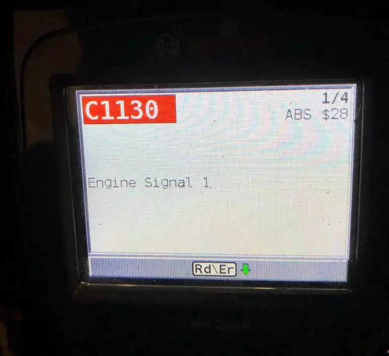
(Image credit: JustAnswer)
So can you drive with the C1130 trouble code present? Yes, you can. However, it is advisable not to ignore the C1130 code and seek proper diagnosis and repair as soon as possible. Continuing to drive with this code unresolved may compromise the functionality of safety systems, potentially increasing the risk of accidents or reduced braking performance.
Signs Of The C1130 Nissan Code
Here are some common symptoms associated with the C1130 code:
- Check engine light and/or slip indicator light illuminated
- Refusal to go into 4WD
Due to the potential impact on safety features, the C1130 code may also result in the following warning signs:
- Malfunctioning or disabled FEB system
- Inoperative or erratic ICC
- Unusual braking behavior
- Traction control issues
Read more: Nissan Dashboard Warning Lights and Meanings (FULL list, FREE Download)
Triggers Behind The C1130 Nissan Code
The C1130 code in Nissan vehicles may have the following causes:
- Connection issues between the ECM and the related system
- ECM internal fault
- Corroded connector (typical of a car that has water damage)
- Other specific causes vary depending on ECM-related DTC (P codes) that arise together with the C1130 code
C1130 Nissan Code: A Guide To Diagnosis And Repair
In this section, we will provide step-by-step instructions, along with a list of essential tools and parts needed to address the issue. By following this guide, you can effectively identify and resolve the C1130 code.
Essential Tools And Parts
- OBD-II scanner
- Basic hand tools (wrenches, sockets, etc.)
- Multimeter
- Wiring harnesses
- Connectors and terminals
- Replacement of ECM, ABS control unit, ABS speed sensor (if necessary)
Step-by-Step Procedure
Step 1: Connect an OBD-II scanner to retrieve all stored codes and freeze frame data.
Step 2: Diagnose, repair, and erase any ECM-related diagnostic trouble codes (P-codes) that are found. It is crucial to address these codes first.
Step 3: If no ECM-related codes are found, the problem may reside in the ECM or the ABS system. Proceed with the following steps:
- Perform an ECM self-diagnosis. If you detect any issues, proceed to repair or replace the identified faulty components.
- Perform another self-diagnosis for the ABS actuator and control unit. If problems are found, make the necessary repairs or replacements as the self-diagnosis indicates.
Step 4: Clear all codes and test the vehicle to ensure the C1130 code does not reappear.
DIY Repair Level And Estimated Costs
The diagnostic and repair procedure for the C1130 code may require advanced-level automotive knowledge and experience. It involves using specialized diagnostic tools and potentially replacing components like the ECM, ABS control unit or repairing wiring harnesses and connectors. If unsure about your DIY capabilities, you should seek assistance from a qualified mechanic or technician.
The estimated costs for main repair tasks can vary depending on factors such as the specific model, location, and labor rates. Below is a table outlining estimated costs for common repair tasks related to the C1130 code:
| Repair Task | Estimated Cost |
| Diagnostic fee | $50 – $150 (may vary by location) |
| Electrical circuit repair | $100 – $300 (parts and labor) |
| ECM replacement | $300 – $600 (parts and labor) |
| ABS control unit replacement | $200 – $500 (parts and labor) |
Please note that these are rough estimates, and actual costs may differ. It is recommended to consult with a professional for accurate cost assessments based on your specific vehicle and location.
C1130 Nissan Infographic
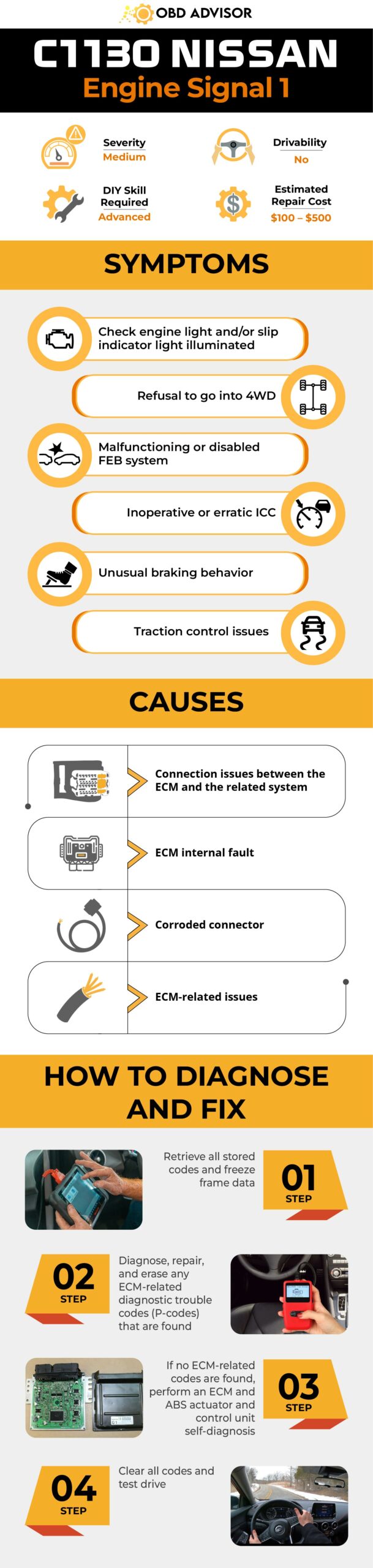
Final Thoughts
In wrapping up, let’s tackle the C1130 code in your Nissan vehicle so you can enjoy a smoother ride and keep your safety features working perfectly.
Whether you’re a DIY superstar or prefer the expertise of a professional, taking action is key. Always remember, safety is the star of the show here.
If you found this information helpful, feel free to comment and share it with others. For further assistance, you can use our convenient OBD code lookup tool and explore our comprehensive Nissan OBD2 code list.
Drive safely and enjoy your Nissan!
Reference Sources
- Babcox Media Youtube Channel, How To Resolve DTC C1130 For Nissan Vehicles | Tech Minute.
- Nissan North America, 2016, TSB BR16-004: DIAGNOSIS INFORMATION FOR ABS DTC C1130.
- CarParts, C1130 Code: Engine Signal 1.
- 2CarPros, Code C1130: My Car Will Move a Little.
- 2CarPros, 2005 Nissan Quest C1130 Engine 1 Fuel Cut System Fault.
- Titan XD Forum, C1130 Code.
Audi Fault Codes: Comprehensive List For OBD2 Diagnostic
Audi Fault Codes: Comprehensive List For OBD2 Diagnostic
Attention Audi owners and DIY mechanics! Get ready to unlock the secrets behind Audi fault codes and take control of your diagnostics.
In this exciting guide, we’re diving deep into the world of Audi OBD2 codes, providing you with information to help you diagnose your car and keep it running smoothly.
Get ready to explore our FREE codes list!
Audi OBD2 Codes List And Definition [FULL]
Free download: Full Audi OBD2 Trouble Codes List and Meaning PDF
Our user-friendly OBD2 codes list is your ultimate resource for decoding and understanding Audi fault codes. It’s divided into four sections: Powertrain, Network, Body, and Chassis, making it easy to find the specific codes related to the engine, network, body control, and chassis issues.
Note: Quickly locate the codes you need using the search box in the table below.
Powertrain (P) Codes List
| Code | Definition |
|---|---|
| P0010 | -A- Camshaft Pos. Actuator Circ. Bank 1 Malfunction |
| P0020 | -A- Camshaft Pos. Actuator Circ. Bank 2 Malfunction |
| P0065 | Air Assisted Injector Control Range/Performance |
| P0066 | Air Assisted Injector Control Low Input/Short to ground |
| P0067 | Air Assisted Injector Control Input/Short to B+ |
| P0101 | Mass or Volume Air Flow Circ Range/Performance |
| P0102 | Mass or Volume Air Flow Circ Low Input |
| P0103 | Mass or Volume Air Flow Circ High Input |
| P0105 | Manifold Abs.Pressure or Bar.Pressure Voltage supply |
| P0106 | Manifold Abs.Pressure or Bar.Pressure Range/Performance |
| P0107 | Manifold Abs.Pressure or Bar.Pressure Low Input |
| P0108 | Manifold Abs.Pressure or Bar.Pressure High Input |
| P0112 | Intake Air Temp.Circ Low Input |
| P0113 | Intake Air Temp.Circ High Input |
| P0116 | Engine Coolant Temp.Circ Range/Performance |
| P0117 | Engine Coolant Temp.Circ Low Input |
| P0118 | Engine Coolant Temp.Circ High Input |
| P0120 | Throttle/Pedal Pos.Sensor A Circ Malfunction |
| P0121 | Throttle/Pedal Pos.Sensor A Circ Range/Performance |
| P0122 | Throttle/Pedal Pos.Sensor A Circ Low Input |
| P0123 | Throttle/Pedal Pos.Sensor A Circ High Input |
| P0125 | Insufficient Coolant Temp.for Closed Loop Fuel Control |
| P0128 | Coolant Thermostat/Valve Temperature below control range |
| P0130 | O2 Sensor Circ.,Bank1-Sensor1 Malfunction |
| P0131 | O2 Sensor Circ.,Bank1-Sensor1 Low Voltage |
| P0132 | O2 Sensor Circ.,Bank1-Sensor1 High Voltage |
| P0133 | O2 Sensor Circ.,Bank1-Sensor1 Slow Response |
| P0134 | O2 Sensor Circ.,Bank1-Sensor1 No Activity Detected |
| P0135 | O2 Sensor Heater Circ.,Bank1-Sensor1 Malfunction |
| P0136 | O2 Sensor Circ.,Bank1-Sensor2 Malfunction |
| P0137 | O2 Sensor Circ.,Bank1-Sensor2 Low Voltage |
| P0138 | O2 Sensor Circ.,Bank1-Sensor2 High Voltage |
| P0139 | O2 Sensor Circ.,Bank1-Sensor2 Slow Response |
| P0140 | O2 Sensor Circ.,Bank1-Sensor2 No Activity Detected |
| P0141 | O2 Sensor Heater Circ.,Bank1-Sensor2 Malfunction |
| P0150 | O2 Sensor Circ.,Bank2-Sensor1 Malfunction |
| P0151 | O2 Sensor Circ.,Bank2-Sensor1 Low Voltage |
| P0152 | O2 Sensor Circ.,Bank2-Sensor1 High Voltage |
| P0153 | O2 Sensor Circ.,Bank2-Sensor1 Slow Response |
| P0154 | O2 Sensor Circ.,Bank2-Sensor1 No Activity Detected |
| P0155 | O2 Sensor Heater Circ.,Bank2-Sensor1 Malfunction |
| P0156 | O2 Sensor Circ.,Bank2-Sensor2 Malfunction |
| P0157 | O2 Sensor Circ.,Bank2-Sensor2 Low Voltage |
| P0158 | O2 Sensor Circ.,Bank2-Sensor2 High Voltage |
| P0159 | O2 Sensor Circ.,Bank2-Sensor2 Slow Response |
| P0160 | O2 Sensor Circ.,Bank2-Sensor2 No Activity Detected |
| P0161 | O2 Sensor Heater Circ.,Bank2-Sensor2 Malfunction |
| P0170 | Fuel Trim,Bank1 Malfunction |
| P0171 | Fuel Trim,Bank1 System too Lean |
| P0172 | Fuel Trim,Bank1 System too Rich |
| P0173 | Fuel Trim,Bank2 Malfunction |
| P0174 | Fuel Trim,Bank2 System too Lean |
| P0175 | Fuel Trim,Bank2 System too Rich |
| P0182 | Fuel temperature sender-G81 Short to ground |
| P0183 | Fuel temperature sender-G81 Interruption/Short to B+ |
| P0197 | Engine Oil Temperature Circuit Low Input |
| P0198 | Engine Oil Temperature Circuit High Input |
| P0201 | Cyl.1, Injector Circuit Fault in electrical circuit |
| P0202 | Cyl.2, Injector Circuit Fault in electrical circuit |
| P0203 | Cyl.3, Injector Circuit Fault in electrical circuit |
| P0204 | Cyl.4, Injector Circuit Fault in electrical circuit |
| P0205 | Cyl.5 Injector Circuit Fault in electrical circuit |
| P0206 | Cyl.6 Injector Circuit Fault in electrical circuit |
| P0207 | Cyl.7 Injector Circuit Fault in electrical circuit |
| P0208 | Cyl.8 Injector Circuit Fault in electrical circuit |
| P0215 | Engine Shut-Off Solenoid Malfunction |
| P0216 | Injector/Injection Timing Control Malfunction |
| P0219 | Engine Overspeed Condition |
| P0221 | Throttle Pos. Sensor -B- Circuit Range/Performance |
| P0222 | Throttle Pos. Sensor -B- Circuit Low Input |
| P0223 | Throttle Pos. Sensor -B- Circuit High Input |
| P0225 | Throttle Pos. Sensor -C- Circuit Voltage supply |
| P0226 | Throttle Pos. Sensor -C- Circuit Range/Performance |
| P0227 | Throttle Pos. Sensor -C- Circuit Low Input |
| P0228 | Throttle Pos. Sensor -C- Circuit Hight Input |
| P0230 | Fuel Pump Primary Circuit Fault in electrical circuit |
| P0234 | Turbocharger Overboost Condition Control limit exceeded |
| P0235 | Turbocharger Boost Sensor (A) Circ Control limit not reached |
| P0236 | Turbocharger Boost Sensor (A) Circ Range/Performance |
| P0237 | Turbocharger Boost Sensor (A) Circ Low Input |
| P0238 | Turbocharger Boost Sensor (A) Circ High Input |
| P0243 | Turbocharger Wastegate Solenoid (A) Open/Short Circuit to Ground |
| P0245 | Turbocharger Wastegate Solenoid (A) Low Input/Short to ground |
| P0246 | Turbocharger Wastegate Solenoid (A) High Input/Short to B+ |
| P0252 | Injection Pump Metering Control (A) Range/Performance |
| P0261 | Cyl.1 Injector Circuit Low Input/Short to ground |
| P0262 | Cyl.1 Injector Circuit High Input/Short to B+ |
| P0264 | Cyl.2 Injector Circuit Low Input/Short to ground |
| P0265 | Cyl.2 Injector Circuit High Input/Short to B+ |
| P0267 | Cyl.3 Injector Circuit Low Input/Short to ground |
| P0268 | Cyl.3 Injector Circuit High Input/Short to B+ |
| P0270 | Cyl.4 Injector Circuit Low Input/Short to ground |
| P0271 | Cyl.4 Injector Circuit High Input/Short to B+ |
| P0273 | Cyl.5 Injector Circuit Low Input/Short to ground |
| P0274 | Cyl.5 Injector Circuit High Input/Short to B+ |
| P0276 | Cyl.6 Injector Circuit Low Input/Short to ground |
| P0277 | Cyl.6 Injector Circuit High Input/Short to B+ |
| P0279 | Cyl.7 Injector Circuit Low Input/Short to ground |
| P0280 | Cyl.7 Injector Circuit High Input/Short to B+ |
| P0282 | Cyl.8 Injector Circuit Low Input/Short to ground |
| P0283 | Cyl.8 Injector Circuit High Input/Short to B+ |
| P0300 | Random/Multiple Cylinder Misfire Detected |
| P0301 | Cyl.1 Misfire Detected |
| P0302 | Cyl.2 Misfire Detected |
| P0303 | Cyl.3 Misfire Detected |
| P0304 | Cyl.4 Misfire Detected |
| P0305 | Cyl.5 Misfire Detected |
| P0306 | Cyl.6 Misfire Detected |
| P0307 | Cyl.7 Misfire Detected |
| P0308 | Cyl.8 Misfire Detected |
| P0313 | Misfire Detected Low Fuel Level |
| P0314 | Single Cylinder Misfire |
| P0321 | Ign./Distributor Eng.Speed Inp.Circ Range/Performance |
| P0322 | Ign./Distributor Eng.Speed Inp.Circ No Signal |
| P0325 | Knock Sensor 1 Circuit Electrical Fault in Circuit |
| P0326 | Knock Sensor 1 Circuit Range/Performance |
| P0327 | Knock Sensor 1 Circ Low Input |
| P0328 | Knock Sensor 1 Circ High Input |
| P0332 | Knock Sensor 2 Circ Low Input |
| P0333 | Knock Sensor 2 Circ High Input |
| P0335 | Crankshaft Pos. Sensor (A) Circ Malfunction |
| P0336 | Crankshaft Pos. Sensor (A) Circ Range/Performance/Missing tooth |
| P0337 | Crankshaft Pos.Sensor (A) Circ Low Input |
| P0340 | Camshaft Pos. Sensor (A) Circ Incorrect allocation |
| P0341 | Camshaft Pos.Sensor Circ Range/Performance |
| P0342 | Camshaft Pos.Sensor Circ Low Input |
| P0343 | Camshaft Pos.Sensor Circ High Input |
| P0351 | Ignition Coil (A) Cyl.1 Prim./Sec. Circ Malfunction |
| P0352 | Ignition Coil (B) Cyl.2 Prim./Sec. Circ Malfunction |
| P0353 | Ignition Coil (C) Cyl.3 Prim./Sec. Circ Malfunction |
| P0354 | Ignition Coil (D) Cyl.4 Prim./Sec. Circ Malfunction |
| P0355 | Ignition Coil (E) Cyl.5 Prim./Sec. Circ Malfunction |
| P0356 | Ignition Coil (F) Cyl.6 Prim./Sec. Circ Malfunction |
| P0357 | Ignition Coil (G) Cyl.7 Prim./Sec. Circ Malfunction |
| P0358 | Ignition Coil (H) Cyl.8 Prim./Sec. Circ Malfunction |
| P0380 | Glow Plug/Heater Circuit (A) Electrical Fault in Circuit |
| P0400 | Exhaust Gas Recirc.Flow Malfunction |
| P0401 | Exhaust Gas Recirc.Flow Insufficient Detected |
| P0402 | Exhaust Gas Recirc.Flow Excessive Detected |
| P0403 | Exhaust Gas Recirc. Contr. Circ Malfunction |
| P0404 | Exhaust Gas Recirc. Contr. Circ Range/Performance |
| P0405 | Exhaust Gas Recirc. Sensor (A) Circ Low Input |
| P0406 | Exhaust Gas Recirc. Sensor (A) Circ High Input |
| P0407 | Exhaust Gas Recirc. Sensor (B) Circ Low Input |
| P0408 | Exhaust Gas Recirc. Sensor (B) Circ High Input |
| P0410 | Sec.Air Inj.Sys Malfunction |
| P0411 | Sec.Air Inj.Sys. Incorrect Flow Detected |
| P0412 | Sec.Air Inj.Sys.Switching Valve A Circ Malfunction |
| P0418 | Sec. Air Inj. Sys. Relay (A) Contr. Circ Malfunction |
| P0420 | Catalyst System,Bank1 Efficiency Below Threshold |
| P0422 | Main Catalyst,Bank1 Below Threshold |
| P0427 | Catalyst Temperature Sensor, Bank 1 Low Input/Short to ground |
| P0428 | Catalyst Temperature Sensor, Bank 1 High Input/Open/Short Circuit to B+ |
| P0432 | Main Catalyst,Bank2 Efficiency Below Threshold |
| P0436 | Catalyst Temperature Sensor, Bank 2 Range/Performance |
| P0437 | Catalyst Temperature Sensor, Bank 2 Low Input/Short to ground |
| P0438 | Catalyst Temperature Sensor, Bank 2 High Input/Open/Short Circuit to B+ |
| P0440 | EVAP Emission Contr.Sys. Malfunction |
| P0441 | EVAP Emission Contr.Sys.Incorrect Purge Flow |
| P0442 | EVAP Emission Contr.Sys.(Small Leak) Leak Detected |
| P0443 | EVAP Emiss. Contr. Sys. Purge Valve Circ Electrical Fault in Circuit |
| P0452 | EVAP Emission Contr.Sys.Press.Sensor Low Input |
| P0453 | EVAP Emission Contr.Sys.Press.Sensor High Input |
| P0455 | EVAP Emission Contr.Sys.(Gross Leak) Leak Detected |
| P0461 | Fuel Level Sensor Circ Range/Performance |
| P0462 | Fuel Level Sensor Circuit Low Input |
| P0463 | Fuel Level Sensor Circuit High Input |
| P0501 | Vehicle Speed Sensor Range/Performance |
| P0503 | Vehicle Speed Sensor Intermittent/Erratic/High Input |
| P0505 | Idle Control System Malfunction |
| P0506 | Idle Control System RPM Lower than Expected |
| P0507 | Idle Control System Higher than Expected |
| P0510 | Closed Throttle Pos.Switch Malfunction |
| P0531 | A/C Refrigerant Pressure Sensor Circuit Range/Performance |
| P0532 | A/C Refrigerant Pressure Sensor Circuit Low Input |
| P0533 | A/C Refrigerant Pressure Sensor Circuit High Input |
| P0551 | Power Steering Pressure Sensor Circuit Range/Performance |
| P0560 | System Voltage Malfunction |
| P0562 | System Voltage Low Voltage |
| P0563 | System Voltage High Voltage |
| P0568 | Cruise Control Set Signal Incorrect Signal |
| P0571 | Cruise/Brake Switch (A) Circ Malfunction |
| P0600 | Serial Comm. Link (Data Bus) Message Missing |
| P0601 | Internal Contr.Module Memory Check Sum Error |
| P0602 | Control Module Programming Error/Malfunction |
| P0603 | Internal Contr.Module (KAM) Error |
| P0604 | Internal Contr.Module Random Access Memory (RAM) Error |
| P0605 | Internal Contr.Module ROM Test Error |
| P0606 | ECM/PCM Processor |
| P0642 | Knock Control Control Module Malfunction |
| P0645 | A/C Clutch Relay Control Circuit |
| P0650 | MIL Control Circuit Electrical Fault in Circuit |
| P0654 | Engine RPM Output Circuit Electrical Fault in Circuit |
| P0656 | Fuel Level Output Circuit Electrical Fault in Circuit |
| P0700 | Transm.Contr.System Malfunction |
| P0702 | Transm.Contr.System Electrical |
| P0703 | Torque Converter/Brake Switch B Circ Malfunction |
| P0705 | Transm.Range Sensor Circ.(PRNDL Inp.) Malfunction |
| P0706 | Transm.Range Sensor Circ Range/Performance |
| P0707 | Transm.Range Sensor Circ Low Input |
| P0708 | Transm.Range Sensor Circ High Input |
| P0710 | Transm.Fluid Temp.Sensor Circ. Malfunction |
| P0711 | Transm.Fluid Temp.Sensor Circ. Range/Performance |
| P0712 | Transm.Fluid Temp.Sensor Circ. Low Input |
| P0713 | Transm.Fluid Temp.Sensor Circ. High Input |
| P0715 | Input Turbine/Speed Sensor Circ. Malfunction |
| P0716 | Input Turbine/Speed Sensor Circ. Range/Performance |
| P0717 | Input Turbine/Speed Sensor Circ. No Signal |
| P0721 | Output Speed Sensor Circ Range/Performance |
| P0722 | Output Speed Sensor Circ No Signal |
| P0725 | Engine Speed Inp.Circ. Malfunction |
| P0726 | Engine Speed Inp.Circ. Range/Performance |
| P0727 | Engine Speed Inp.Circ. No Signal |
| P0730 | Gear Incorrect Ratio |
| P0731 | Gear 1 Incorrect Ratio |
| P0732 | Gear 2 Incorrect Ratio |
| P0733 | Gear 3 Incorrect Ratio |
| P0734 | Gear 4 Incorrect Ratio |
| P0735 | Gear 5 Incorrect Ratio |
| P0740 | Torque Converter Clutch Circ Malfunction |
| P0741 | Torque Converter Clutch Circ Performance or Stuck Off |
| P0748 | Pressure Contr.Solenoid Electrical |
| P0750 | Shift Solenoid A malfunction |
| P0751 | Shift Solenoid A Performance or Stuck Off |
| P0752 | Shift Solenoid A Stuck On |
| P0753 | Shift Solenoid A Electrical |
| P0756 | Shift Solenoid B Performance or Stuck Off |
| P0757 | Shift Solenoid B Stuck On |
| P0758 | Shift Solenoid B Electrical |
| P0761 | Shift Solenoid C Performance or Stuck Off |
| P0762 | Shift Solenoid C Stuck On |
| P0763 | Shift Solenoid C Electrical |
| P0768 | Shift Solenoid D Electrical |
| P0773 | Shift Solenoid E Electrical |
| P0790 | Normal/Performance Switch Circ Malfunction |
| P1004 | Torque difference cylinder 1 Limiting value exceeded |
| P1005 | Torque difference cylinder 2 Limiting value exceeded |
| P1006 | Torque difference cylinder 3 Limiting value exceeded |
| P1007 | Torque difference cylinder 4 Limiting value exceeded |
| P1009 | Air mass meter 1/2 implausible signal from load detection |
| P100F | Fuel Rail Injection Valves |
| P10A0 | RFP Powerstage, signal range check |
| P10A4 | RFP Actuator, functional check |
| P1101 | O2 Sensor Circ.,Bank1-Sensor1Voltage too Low/Air Leak |
| P1102 | O2 Sensor Heating Circ.,Bank1-Sensor1 Short to B+ |
| P1103 | O2 Sensor Heating Circ.,Bank1-Sensor1 Output too Low |
| P1103 | O2 Sensor Circuit (Bank 1-Sensor 1) Output Too Low |
| P1104 | Bank1-Sensor2 Voltage too Low/Air Leak |
| P1105 | O2 Sensor Heating Circ.,Bank1-Sensor2 Short to B+ |
| P1105 | O2 Sensor Circuit (Bank 1-Sensor 2) Short to B+ |
| P1106 | O2 Sensor Circ.,Bank2-Sensor1 Voltage too Low/Air Leak |
| P1107 | O2 Sensor Heating Circ.,Bank2-Sensor1 Short to B+ |
| P1107 | O2 Sensor Circuit (Bank 2-Sensor 1) Voltage Too Low |
| P1108 | O2 Sensor Heating Circ.,Bank2-Sensor1 Output too Low |
| P1109 | O2 Sensor Circ.,Bank2-Sensor2 Voltage too Low/Air Leak |
| P1110 | O2 Sensor Heating Circ.,Bank2-Sensor2 Short to B+ |
| P1110 | O2 Sensor Circuit (Bank 2-Sensor 2) Short to B+ |
| P1111 | O2 Control (Bank 1) System too lean |
| P1112 | O2 Control (Bank 1) System too rich |
| P1113 | Bank1-Sensor1 Internal Resistance too High |
| P1113 | O2 Control (Bank 1 Sensor 1) Internal Resistance Too High |
| P1114 | Bank1-Sensor2 Internal Resistant too High |
| P1114 | O2 Control (Bank 1 Sensor 2) Internal Resistance Too High |
| P1115 | O2 Sensor Heater Circ.,Bank1-Sensor1 Short to Ground |
| P1115 | O2 Control (Bank 1 Sensor 1) Short to Ground |
| P1116 | O2 Sensor Heater Circ.,Bank1-Sensor1 Open |
| P1116 | O2 Control (Bank 1 Sensor 1) Open |
| P1117 | O2 Sensor Heater Circ.,Bank1-Sensor2 Short to Ground |
| P1117 | O2 Control (Bank 1 Sensor 2) Open |
| P1118 | O2 Sensor Heater Circ.,Bank1-Sensor2 Open |
| P1118 | O2 Sensor Heater Circ. (Bank 1-Sensor2) Open |
| P1119 | O2 Sensor Heater Circ.,Bank2-Sensor1 Short to Ground |
| P1120 | O2 Sensor Heater Circ.,Bank2-Sensor1 Open |
| P1121 | O2 Sensor Heater Circ.,Bank2-Sensor2 Short to Ground |
| P1122 | O2 Sensor Heater Circ.,Bank2-Sensor2 Open |
| P1123 | Long Term Fuel Trim Add.Air.,Bank1 System too Rich |
| P1124 | Long Term Fuel Trim Add.Air.,Bank1 System too Lean |
| P1125 | Long Term Fuel Trim Add.Air.,Bank2 System too Rich |
| P1126 | Long Term Fuel Trim Add.Air.,Bank2 System too Lean |
| P1127 | Long Term Fuel Trim mult.,Bank1 System too Rich |
| P1127 | Long Term Fuel Trim Add. Air. Bank 1 System Too Rich |
| P1128 | Long Term Fuel Trim mult.,Bank1 System too Lean |
| P1128 | Long Term Fuel Trim Add. Air. Bank 1 System Too Lean |
| P1129 | Long Term Fuel Trim mult.,Bank2 System too Rich |
| P1129 | Long Term Fuel Trim at Rich Limit |
| P1130 | Long Term Fuel Trim mult.,Bank2 System too Lean |
| P1130 | Long Term Fuel Trim at Lean Limit |
| P1131 | Bank2-Sensor1 Internal Rsistance too High |
| P1132 | O2 Sensor Heating Circ.,Bank1+2-Sensor1 Short to B+ |
| P1133 | O2 Sensor Heating Circ.,Bank1+2-Sensor1 Electrical Malfunction |
| P1134 | O2 Sensor Heating Circ.,Bank1+2-Sensor2 Short to B+ |
| P1135 | O2 Sensor Heating Circ.,Bank1+2-Sensor2 Electrical Malfunction |
| P1136 | Long Term Fuel Trim Add.Fuel,Bank1 System too Lean |
| P1136 | Long Term Fuel Trim Add. Fuel, Bank 1 System Too Lean |
| P1137 | Long Term Fuel Trim Add.Fuel,Bank1 System too Rich |
| P1137 | Long Term Fuel Trim Add. Fuel, Bank 1 System Too Rich |
| P1138 | Long Term Fuel Trim Add.Fuel,Bank2 System too Lean |
| P1138 | Long Term Fuel Trim Add. Fuel, Bank 2 System Too Lean |
| P1139 | Long Term Fuel Trim Add.Fuel,Bank2 System too Rich |
| P1139 | Long Term Fuel Trim Add. Fuel, Bank 2 System Too Rich |
| P1140 | Bank2-Sensor2 Internal Resistance too High |
| P1141 | Load Calculation Cross Check Range/Performance |
| P1142 | Load Calculation Cross Check Lower Limit Exceeded |
| P1143 | Load Calculation Cross Check Upper Limit Exceeded |
| P1143 | Load Calculation Cross Check Upper Limit |
| P1144 | Mass or Volume Air Flow Circ Open/Short to Ground |
| P1145 | Mass or Volume Air Flow Circ Short to B+ |
| P1146 | Mass or Volume Air Flow Circ Supply Malfunction |
| P1146 | Air mass meter -G70 supply voltage |
| P1147 | O2 Control (Bank 2) System too lean |
| P1148 | O2 Control (Bank 2) System too rich |
| P1149 | O2 Control (Bank 1) Out of range |
| P1150 | O2 Control (Bank 2) Out of range |
| P1151 | Bank1, Long Term Fuel Trim, Range 1 Leanness Lower Limit Exceeded |
| P1152 | Bank1, Long Term Fuel Trim, Range 2 Leanness Lower Limit Exceeded |
| P1154 | Manifold Switch Over Malfunction |
| P1155 | Manifold Abs.Pressure Sensor Circ. Short to B+ |
| P1156 | Manifold Abs.Pressure Sensor Circ. Open/Short to Ground |
| P1157 | Manifold Abs.Pressure Sensor Circ. Power Supply Malfunction |
| P1158 | Manifold Abs.Pressure Sensor Circ. Range/Performance |
| P1160 | Manifold Temp.Sensor Circ. Short to Ground |
| P1160 | Intake Air Temperature (IAT) Sensor -G72- Short circuit to Ground (GND) |
| P1161 | Manifold Temp.Sensor Circ. Open/Short to B+ |
| P1161 | Intake Air Temperature (IAT) Sensor -G72-Open circuit/short circuit to B+ |
| P1162 | Fuel Temp.Sensor Circ. Short to Ground |
| P1163 | Fuel Temp.Sensor Circ. Open/Short to B+ |
| P1164 | Fuel Temperature Sensor Range/Performance/Incorrect Signal |
| P1165 | Bank1, Long Term Fuel Trim, Range 1 Rich Limit Exceeded |
| P1166 | Bank1, Long Term Fuel Trim, Range 2 Rich Limit Exceeded |
| P1171 | Throttle Actuation Potentiometer Sign.2 Range/Performance |
| P1172 | Throttle Actuation Potentiometer Sign.2 Signal too Low |
| P1173 | Throttle Actuation Potentiometer Sign.2 Signal too High |
| P1174 | Fuel Trim, Bank 1 Different injection times |
| P1176 | O2 Correction Behind Catalyst,B1 Limit Attained |
| P1176 | O2 Correction Behind Catalyst B1 Limit Attained |
| P1177 | O2 Correction Behind Catalyst,B2 Limit Attained |
| P1177 | O2 Correction Behind Catalyst B2 Limit Attained |
| P1178 | Linear 02 Sensor / Pump Current Open Circuit |
| P1179 | Linear 02 Sensor / Pump Current Short to ground |
| P117A | O2S (Bank 1, Sensor 3) |
| P117C | Post Catalyst Fuel Trim System Too Lean Bank 3 |
| P117D | Post Catalyst Fuel Trim System Too Rich Bank 3 |
| P117E | Post Catalyst Fuel Trim System Too Lean Bank 4 |
| P117F | Post Catalyst Fuel Trim System Too Rich Bank 4 |
| P1180 | Linear 02 Sensor / Pump Current Short to B+ |
| P1181 | Linear 02 Sensor / Reference Voltage Open Circuit |
| P1182 | Linear 02 Sensor / Reference Voltage Short to ground |
| P1183 | Linear 02 Sensor / Reference Voltage Short to B+ |
| P1184 | Linear 02 Sensor / Common Ground Wire Open Circuit |
| P1185 | Linear 02 Sensor / Common Ground Wire Short to ground |
| P1186 | Linear 02 Sensor / Common Ground Wire Short to B+ |
| P1187 | Linear 02 Sensor / Compens. Resistor Open Circuit |
| P1188 | Linear 02 Sensor / Compens. Resistor Short to ground |
| P1189 | Linear 02 Sensor / Compens. Resistor Short to B+ |
| P1190 | Linear 02 Sensor / Reference Voltage Incorrect Signal |
| P1196 | O2 Sensor Heater Circ.,Bank1-Sensor1 Electrical Malfunction |
| P1196 | O2 Sensor Heater Circuit (Bank 1-Sensor 1) Electrical Malfunction |
| P1197 | O2 Sensor Heater Circ.,Bank2-Sensor1 Electrical Malfunction |
| P1197 | O2 Sensor Heater Circuit (Bank 2-Sensor 1) Electrical Malfunction |
| P1198 | O2 Sensor Heater Circ.,Bank1-Sensor2 Electrical Malfunction |
| P1198 | O2 Sensor Heater Circuit (Bank 1-Sensor 2) Electrical Malfunction |
| P1199 | O2 Sensor Heater Circ.,Bank2-Sensor2 Electrical Malfunction |
| P1199 | O2 Sensor Heater Circuit (Bank 2-Sensor 2) Electrical Malfunction |
| P1201 | Cyl.1-Fuel Inj.Circ. Electrical Malfunction |
| P1201 | Cylinder 1 Fuel Injection Circuit Electrical Malfunction |
| P1202 | Cyl.2-Fuel Inj.Circ. Electrical Malfunction |
| P1202 | Cylinder 2 Fuel Injection Circuit Electrical Malfunction |
| P1203 | Cyl.3-Fuel Inj.Circ. Electrical Malfunction |
| P1203 | Cylinder 3 Fuel Injection Circuit Electrical Malfunction |
| P1204 | Cyl.4-Fuel Inj.Circ. Electrical Malfunction |
| P1204 | Cylinder 4 Fuel Injection Circuit Electrical Malfunction |
| P1205 | Cyl.5-Fuel Inj.Circ. Electrical Malfunction |
| P1206 | Cyl.6-Fuel Inj.Circ. Electrical Malfunction |
| P1207 | Cyl.7-Fuel Inj.Circ. Electrical Malfunction |
| P1208 | Cyl.8-Fuel Inj.Circ. Electrical Malfunction |
| P1209 | Intake valves for cylinder shut-off Short circuit to ground |
| P1210 | Intake valves for cylinder shut-off Short to B+ |
| P1211 | Intake valves for cylinder shut-off Open circuit |
| P1213 | Cyl.1-Fuel Inj.Circ. Short to B+ |
| P1213 | Cylinder 1 Fuel Injection Circuit Short to B+ |
| P1214 | Cyl.2-Fuel Inj.Circ. Short to B+ |
| P1214 | Cylinder 2 Fuel Injection Circuit Short to B+ |
| P1215 | Cyl.3-Fuel Inj.Circ. Short to B+ |
| P1215 | Cylinder 3 Fuel Injection Circuit Short to B+ |
| P1216 | Cyl.4-Fuel Inj.Circ. Short to B+ |
| P1216 | Cylinder 4 Fuel Injection Circuit Short to B+ |
| P1217 | Cyl.5-Fuel Inj.Circ. Short to B+ |
| P1217 | Cylinder 5 Fuel Injection Circuit Short to B+ |
| P1218 | Cyl.6-Fuel Inj.Circ. Short to B+ |
| P1218 | Cylinder 6 Fuel Injection Circuit Short to B+ |
| P1219 | Cyl.7-Fuel Inj.Circ. Short to B+ |
| P1220 | Cyl.8-Fuel Inj.Circ. Short to B+ |
| P1221 | Cylinder shut-off exhaust valves Short circuit to ground |
| P1222 | Cylinder shut-off exhaust valves Short to B+ |
| P1223 | Cylinder shut-off exhaust valves Open circuit |
| P1225 | Cyl.1-Fuel Inj.Circ. Short to Ground |
| P1225 | Cylinder 1 Fuel Injection Circuit Short to Ground |
| P1226 | Cyl.2-Fuel Inj.Circ. Short to Ground |
| P1226 | Cylinder 2 Fuel Injection Circuit Short to Ground |
| P1227 | Cyl.3-Fuel Inj.Circ. Short to Ground |
| P1227 | Cylinder 3 Fuel Injection Circuit Short to Ground |
| P1228 | Cyl.4-Fuel Inj.Circ. Short to Ground |
| P1228 | Cylinder 4 Fuel Injection Circuit Short to Ground |
| P1229 | Cyl.5-Fuel Inj.Circ. Short to Ground |
| P1229 | Cylinder 5 Fuel Injection Circuit Short to Ground |
| P1230 | Cyl.6-Fuel Inj.Circ. Short to Ground |
| P1230 | Cylinder 6 Fuel Injection Circuit Short to Ground |
| P1231 | Cyl.7-Fuel Inj.Circ. Short to Ground |
| P1232 | Cyl.8-Fuel Inj.Circ. Short to Ground |
| P1237 | Cyl.1-Fuel Inj.Circ. Open Circ. |
| P1237 | Cylinder 1 Fuel Injection Circuit Open Circuit |
| P1238 | Cyl.2-Fuel Inj.Circ. Open Circ. |
| P1238 | Cylinder 2 Fuel Injection Circuit Open Circuit |
| P1239 | Cyl.3-Fuel Inj.Circ. Open Circ. |
| P1239 | Cylinder 3 Fuel Injection Circuit Open Circuit |
| P1240 | Cyl.4-Fuel Inj.Circ. Open Circ. |
| P1240 | Cylinder 4 Fuel Injection Circuit Open Circuit |
| P1241 | Cyl.5-Fuel Inj.Circ. Open Circ. |
| P1241 | Cylinder 5 Fuel Injection Circuit Open Circuit |
| P1242 | Cyl.6-Fuel Inj.Circ. Open Circ. |
| P1242 | Cylinder 6 Fuel Injection Circuit Open Circuit |
| P1243 | Cyl.7-Fuel Inj.Circ. Open Circ. |
| P1244 | Cyl.8-Fuel Inj.Circ. Open Circ. |
| P1245 | Needle Lift Sensor Circ. Short to Ground |
| P1246 | Needle Lift Sensor Circ. Range/Performance |
| P1247 | Needle Lift Sensor Circ. Open/Short to B+ |
| P1248 | Injection Start Control Deviation |
| P1249 | Fuel consumption signal Electrical Fault in Circuit |
| P1250 | Fuel Level Too Low |
| P1250 | Fuel Pressure Regulator Control Circuit Malfunction (Fuel Level too Low) |
| P1251 | Start of Injection Solenoid Circ Short to B+ |
| P1252 | Start of Injection Solenoid Circ Open/Short to Ground |
| P1253 | Fuel consumption signal Short to ground |
| P1254 | Fuel consumption signal Short to B+ |
| P1255 | Engine Coolant Temp.Circ Short to Ground |
| P1255 | Engine Coolant Temperature (ECT) Sensor, Short to Ground |
| P1256 | Engine Coolant Temp.Circ Open/Short to B+ |
| P1256 | Engine Coolant Temperature (ECT) Sensor, Open circuit/short to B+ |
| P1257 | Engine Coolant System Valve Open |
| P1258 | Engine Coolant System Valve Short to B+ |
| P1259 | Engine Coolant System Valve Short to Ground |
| P1280 | Fuel Inj.Air Contr.Valve Circ. Flow too Low |
| P1283 | Fuel Inj.Air Contr.Valve Circ. Electrical Malfunction |
| P1284 | Fuel Inj.Air Contr.Valve Circ. Open |
| P1285 | Fuel Inj.Air Contr.Valve Circ. Short to Ground |
| P1286 | Fuel Inj.Air Contr.Valve Circ. Short to B+ |
| P1287 | Turbocharger bypass valve open |
| P1288 | Turbocharger bypass valve short to B+ |
| P1289 | Turbocharger bypass valve short to ground |
| P1295 | Turbocharger Bypass Valve Throughput Faulty |
| P1296 | Cooling system malfunction |
| P1297 | Connection turbocharger – throttle valve pressure hose |
| P1297 | Connection Turbocharger/Throttle Valve Pressure Hose |
| P129B | Fuel Pressure Regulator 2 Control Circuit |
| P129C | Fuel Pressure Regulator 2 Control Circuit Low |
| P129D | Fuel Pressure Regulator 2 Control Circuit High |
| P12A1 | Fuel Rail Pressure Sensor Inappropriately Low |
| P12A2 | Fuel Rail Pressure Sensor Inappropriately High |
| P12A4 | Fuel Rail Pump Control Valve Stuck Closed |
| P12A5 | Fuel Rail Pressure Sensor High Pressure System |
| P12A6 | Fuel Rail Pressure Sensor High Pressure System |
| P12A7 | Fuel Rail Pressure Control valve |
| P1300 | Misfire detected Reason: Fuel level too low |
| P1300 | Misfire Detected Low Fuel |
| P1319 | Knock Sensor 1 Circ. Short to Ground |
| P1320 | Knock Sensor 2 Circ. Short to Ground |
| P1321 | Knock Sensor 3 Circ. Low Input |
| P1322 | Knock Sensor 3 Circ. High Input |
| P1323 | Knock Sensor 4 Circ. Low Input |
| P1324 | Knock Sensor 4 Circ. High Input |
| P1325 | Cyl.1-Knock Contr. Limit Attained |
| P1325 | Cylinder 1-Knock Control Limit Attained |
| P1326 | Cyl.2-Knock Contr. Limit Attained |
| P1326 | Cylinder 2-Knock Control Limit Attained |
| P1327 | Cyl.3-Knock Contr. Limit Attained |
| P1327 | Cylinder 3-Knock Control Limit Attained |
| P1328 | Cyl.4-Knock Contr. Limit Attained |
| P1328 | Cylinder 4-Knock Control Limit Attained |
| P1329 | Cyl.5-Knock Contr. Limit Attained |
| P1329 | Cylinder 5-Knock Control Limit Attained |
| P1330 | Cyl.6-Knock Contr. Limit Attained |
| P1330 | Cylinder 6-Knock Control Limit Attained |
| P1331 | Cyl.7-Knock Contr. Limit Attained |
| P1332 | Cyl.8-Knock Contr. Limit Attained |
| P1335 | Engine Torque Monitoring 2 Control Limint Exceeded |
| P1335 | Engine Torque Monitoring 2 Control Limit Exceeded |
| P1336 | Engine Torque Monitoring Adaptation at limit |
| P1336 | Engine Torque Monitoring Control Limit Exceeded |
| P1337 | Camshaft Pos.Sensor,Bank1 Short to Ground |
| P1337 | Camshaft Position Sensor (Bank 1) Short to Ground |
| P1338 | Camshaft Pos.Sensor,Bank1 Open Circ./Short to B+ |
| P1338 | Camshaft Position Sensor (Bank 1) Open/Short to B+ |
| P1339 | Crankshaft Pos./Engine Speed Sensor Cross Connected |
| P1340 | Crankshaft-/Camshaft Pos.Sens.Signals Out of Sequence |
| P1340 | Crankshaft Position/Camshaft Sensor Signal Out of Sequence |
| P1341 | Ignition Coil Power Output Stage 1 Short to Ground |
| P1342 | Ignition Coil Power Output Stage 1 Short to B+ |
| P1343 | Ignition Coil Power Output Stage 2 Short to Ground |
| P1344 | Ignition Coil Power Output Stage 2 Short to B+ |
| P1345 | Ignition Coil Power Output Stage 3 Short to Ground |
| P1346 | Ignition Coil Power Output Stage 3 Short to B+ |
| P1347 | Bank2,Crankshaft-/Camshaft os.Sens.Sign. Out of Sequence |
| P1348 | Ignition Coil Power Output Stage 1 Open Circuit |
| P1349 | Ignition Coil Power Output Stage 2 Open Circuit |
| P1350 | Ignition Coil Power Output Stage 3 Open Circuit |
| P1354 | Modulation Piston Displ.Sensor Circ. Malfunction |
| P1355 | Cyl. 1, ignition circuit Open Circuit |
| P1355 | Cylinder 1 Ignition Circuit Open Circuit |
| P1356 | Cyl. 1, ignition circuit Short to B+ |
| P1356 | Cylinder 1 Ignition Circuit Short to B+ |
| P1357 | Cyl. 1, ignition circuit Short to ground |
| P1357 | Cylinder 1 Ignition Circuit Short to Ground |
| P1358 | Cyl. 2, ignition circuit Open Circuit |
| P1358 | Cylinder 2 Ignition Circuit Open Circuit |
| P1359 | Cyl. 2, ignition circuit Short Circuit to B+ |
| P1359 | Cylinder 2 Ignition Circuit Short to B+ |
| P1360 | Cyl. 2, ignition circuit Short Circuit to Ground |
| P1360 | Cylinder 2 Ignition Circuit Short to Ground |
| P1361 | Cyl. 3, ignition circuit Open Circuit |
| P1361 | Cylinder 3 Ignition Circuit Open Circuit |
| P1362 | Cyl. 3, ignition circuit Short Circuit to B+ |
| P1362 | Cylinder 3 Ignition Circuit Short to B+ |
| P1363 | Cyl. 3, ignition circuit Short Circuit to ground |
| P1363 | Cylinder 3 Ignition Circuit Short to Ground |
| P1364 | Cyl. 4 ignition circuit Open Circuit |
| P1364 | Cylinder 4 Ignition Circuit Open Circuit |
| P1365 | Cyl. 4 ignition circuit Short circuit to B+ |
| P1365 | Cylinder 4 Ignition Circuit Short to B+ |
| P1366 | Cyl. 4 ignition circuit Short circuit to ground |
| P1366 | Cylinder 4 Ignition Circuit Short to Ground |
| P1367 | Cyl. 5, ignition circuit Open Circuit |
| P1368 | Cyl. 5, ignition circuit Short Circuit to B+ |
| P1369 | Cyl. 5, ignition circuit short to ground |
| P1370 | Cyl. 6, ignition circuit Open Circuit |
| P1371 | Cyl. 6, ignition circuit Short Circuit to B+ |
| P1372 | Cyl. 6, ignition circuit short to ground |
| P1373 | Cyl. 7, ignition circuit Open Circuit |
| P1374 | Cyl. 7, ignition circuit Short Circuit to B+ |
| P1375 | Cyl. 7, ignition circuit short to ground |
| P1376 | Cyl. 8, ignition circuit Open Circuit |
| P1377 | Cyl. 8, ignition circuit Short Circuit to B+ |
| P1378 | Cyl. 8, ignition circuit short to ground |
| P1386 | Internal Control Module Knock Control Circ.Error |
| P1386 | Internal Control Module, Knock Control Circuit Error |
| P1387 | Internal Contr. Module altitude sensor error |
| P1387 | Internal Control Module Altitude Sensor Error |
| P1388 | Internal Contr. Module drive by wire error |
| P1388 | Internal Control Module Drive By Wire Error |
| P1391 | Camshaft Pos.Sensor,Bank2 Short to Ground |
| P1391 | Camshaft Position Sensor (Bank 2) Short to Ground |
| P1392 | Camshaft Pos.Sensor,Bank2 Open Circ./Short to B+ |
| P1392 | Camshaft Position Sensor (Bank 2) Open/Short to B+ |
| P1393 | Ignition Coil Power Output Stage 1 Electrical Malfunction |
| P1394 | Ignition Coil Power Output Stage 2 Electrical Malfunction |
| P1395 | Ignition Coil Power Output Stage 3 Electrical Malfunction |
| P1396 | Engine Speed Sensor Missing Tooth |
| P1397 | Engine speed wheel Adaptation limit reached |
| P1398 | Engine RPM signal, TD Short to ground |
| P1399 | Engine RPM signal, TD Short Circuit to B+ |
| P13CE | Sensor for internal pressure of cylinder 1 Electrical malfunction |
| P13CF | Sensor for internal pressure of cylinder 1 Short circuit to ground |
| P13D1 | Sensor for internal pressure of cylinder 2 Electrical malfunction |
| P13D2 | Sensor for internal pressure of cylinder 2 Short circuit to ground |
| P13D3 | Sensor for internal pressure of cylinder 2 Implausible signal |
| P13D4 | Sensor for internal pressure of cylinder 3 Electrical malfunction |
| P13D5 | Sensor for internal pressure of cylinder 3 Short circuit to ground |
| P13D6 | Sensor for internal pressure of cylinder 3 Implausible signal |
| P13D7 | Sensor for internal pressure of cylinder 4 Electrical malfunction |
| P13D8 | Sensor for internal pressure of cylinder 4 Short circuit to ground |
| P13D9 | Sensor for internal pressure of cylinder 4 Implausible signal |
| P13EA | ignition timing monitor |
| P1400 | EGR Valve Circ Electrical Malfunction |
| P1401 | EGR Valve Circ Short to Ground |
| P1402 | EGR Valve Circ Short to B+ |
| P1403 | EGR Flow Deviation |
| P1404 | EGR Flow Basic Setting not carried out |
| P1406 | EGR Temp.Sensor Range/Performance |
| P1407 | EGR Temp.Sensor Signal too Low |
| P1408 | EGR Temp.Sensor Signal too High |
| P1409 | Tank Ventilation Valve Circ. Electrical Malfunction |
| P1409 | Tank Ventilation Valve Circuit Malfunction Conditions |
| P140C | Low Pressure EGR Sensor Position circuit high |
| P1410 | Tank Ventilation Valve Circ. Short to B+ |
| P1410 | Tank Ventilation Valve Circuit Short to B+: |
| P1411 | Sec.Air Inj.Sys.,Bank2 Flow too Flow |
| P1412 | EGR Different.Pressure Sensor Signal too Low |
| P1413 | EGR Different.Pressure Sensor Signal too High |
| P1414 | Sec.Air Inj.Sys.,Bank2 Leak Detected |
| P1417 | Fuel Level Sensor Circ Signal too Low |
| P1418 | Fuel Level Sensor Circ Signal too High |
| P1420 | Sec.Air Inj.Valve Circ Electrical Malfunction |
| P1420 | Secondary Air Injector Valve Circuit Electrical Malfunction |
| P1421 | Sec.Air Inj.Valve Circ Short to Ground |
| P1421 | Secondary Air Injector Valve Circuit Short to Ground |
| P1422 | Sec.Air Inj.Sys.Contr.Valve Circ Short to B+ |
| P1422 | Secondary Air Injector Valve Circuit Short to B+ |
| P1423 | Sec.Air Inj.Sys.,Bank1 Flow too Low |
| P1424 | Sec.Air Inj.Sys.,Bank1 Leak Detected |
| P1424 | Secondary Air Injector System (Bank 1) Leak Detected |
| P1425 | Tank Vent.Valve Short to Ground |
| P1425 | Tank Ventilation Valve Short to Ground |
| P1426 | Tank Vent.Valve Open |
| P1426 | Tank Ventilation Valve Open |
| P1432 | Sec.Air Inj.Valve Open |
| P1432 | Secondary Air Injection Valve Open |
| P1433 | Sec.Air Inj.Sys.Pump Relay Circ. open |
| P1433 | Secondary Air Injection System Pump Relay Circuit Open |
| P1434 | Sec.Air Inj.Sys.Pump Relay Circ. Short to B+ |
| P1434 | Secondary Air Injection System Pump Relay Circuit Short to B+ |
| P1435 | Sec.Air Inj.Sys.Pump Relay Circ. Short to ground |
| P1435 | Secondary Air Injection System Pump Relay Circuit Short to Ground |
| P1436 | Sec.Air Inj.Sys.Pump Relay Circ. Electrical Malfunction |
| P1436 | A/C Evaporator Temperature (ACET) Circuit Low Input |
| P1439 | EGR Potentiometer Error in Basic Seting |
| P1440 | EGR Valve Power Stage Open |
| P1441 | EGR Valve Circ Open/Short to Ground |
| P1442 | EGR Valve Position Sensor Signal too high |
| P1443 | EGR Valve Position Sensor Signal too low |
| P1444 | EGR Valve Position Sensor range/performance |
| P1445 | Catalyst Temp.Sensor 2 Circ. Range/Performance |
| P1446 | Catalyst Temp.Circ Short to Ground |
| P1447 | Catalyst Temp.Circ Open/Short to B+ |
| P1448 | Catalyst Temp.Sensor 2 Circ. Short to Ground |
| P1449 | Catalyst Temp.Sensor 2 Circ. Open/Short to B+ |
| P1450 | Sec.Air Inj.Sys.Circ Short to B+ |
| P1451 | Sec.Air Inj.Sys.Circ Short to Ground |
| P1452 | Sec.Air Inj.Sys. Open Circ. |
| P1453 | Exhaust gas temperature sensor 1 open/short to B+ |
| P1454 | Exhaust gas temperature sensor short 1 to ground |
| P1455 | Exhaust gas temperature sensor 1 range/performance |
| P1456 | Exhaust gas temperature control bank 1 limit attained |
| P1457 | Exhaust gas temperature sensor 2 open/short to B+ |
| P1458 | Exhaust gas temperature sensor 2 short to ground |
| P1459 | Exhaust gas temperature sensor 2 range/performance |
| P1460 | Exhaust gas temperature control bank 2 limit attained |
| P1461 | Exhaust gas temperature control bank 1 Range/Performance |
| P1462 | Exhaust gas temperature control bank 2 Range/Performance |
| P1465 | Additive Pump Short Circuit to B+ |
| P1466 | Additive Pump Open/Short to Ground |
| P1467 | EVAP Canister Purge Solenoid Valve Short Circuit to B+ |
| P1468 | EVAP Canister Purge Solenoid Valve Short Circuit to Ground |
| P1469 | EVAP Canister Purge Solenoid Valve Open Circuit |
| P1470 | EVAP Emission Contr.LDP Circ Electrical Malfunction |
| P1470 | EVAP Emission Control LDP Circuit Electrical Malfunction |
| P1471 | EVAP Emission Contr.LDP Circ Short to B+ |
| P1471 | EVAP Emission Control Leak Detection Pump Circuit Short to B+ |
| P1472 | EVAP Emission Contr.LDP Circ Short to Ground |
| P1472 | EVAP Emission Control Leak Detection Pump Circuit Short to Ground |
| P1473 | EVAP Emission Contr.LDP Circ Open Circ. |
| P1473 | EVAP Emission Control Leak Detection Pump Circuit Open |
| P1474 | EVAP Canister Purge Solenoid Valve electrical malfunction |
| P1475 | EVAP Emission Contr.LDP Circ Malfunction/Signal Circ.Open |
| P1475 | EVAP Emission Control LDP Circuit Malfunction/Signal Circuit Open |
| P1476 | EVAP Emission Contr.LDP Circ Malfunction/Insufficient Vacuum |
| P1476 | EVAP Emission Control LDP Circuit Malfunction/Insufficient Vacuum |
| P1477 | EVAP Emission Contr.LDP Circ Malfunction |
| P1477 | EVAP Emission Control LDP Circuit Malfunction |
| P1478 | EVAP Emission Contr.LDP Circ Clamped Tube Detected |
| P1478 | EVAP Emission Control LDP Circuit Clamped Tube Detected |
| P1489 | Evaporative Emission System Purge Control Valve Circuit High |
| P1490 | Evaporative Emission System Purge Control Valve Circuit Low |
| P1491 | Evaporative Emission System Purge Control Valve CircuitOpen |
| P1494 | Evaporative Emission System Incorrect Purge Flow |
| P1497 | Secondary Air Injection System Insufficient Flow Bank 3 |
| P1498 | Secondary Air Injection System Insufficient Flow Bank 4 |
| P1500 | Fuel Pump Relay Circ. Electrical Malfunction |
| P1500 | Fuel Pump Relay Circuit Electrical Malfunction |
| P1501 | Fuel Pump Relay Circ. Short to Ground |
| P1501 | Fuel Pump Relay Circuit Electrical Short to Ground |
| P1502 | Fuel Pump Relay Circ. Short to B+ |
| P1502 | Fuel Pump Relay Circuit Short to B+ |
| P1503 | Load signal from Alternator Term. DF Range/performance/Incorrect Signal |
| P1504 | Intake Air Sys.Bypass Leak Detected |
| P1505 | Closed Throttle Pos. Does Not Close/Open Circ |
| P1506 | Closed Throttle Pos.Switch Does Not Open/Short to Ground |
| P1507 | Idle Sys.Learned Value Lower Limit Attained |
| P1508 | Idle Sys.Learned Value Upper Limit Attained |
| P1509 | Idle Air Control Circ. Electrical Malfunction |
| P150A | Engine Off Timer Performance |
| P1510 | Idle Air Control Circ. Short to B+ |
| P1511 | Intake Manifold Changeover Valve circuit electrical malfunction |
| P1512 | Intake Manifold Changeover Valve circuit Short to B+ |
| P1513 | Intake Manifold Changeover Valve2 circuit Short to B+ |
| P1514 | Intake Manifold Changeover Valve2 circuit Short to ground |
| P1515 | Intake Manifold Changeover Valve circuit Short to Ground |
| P1516 | Intake Manifold Changeover Valve circuit Open |
| P1516 | Intake Manifold Runner Control Input Error (Bank 1) |
| P1517 | Main Relay Circ. Electrical Malfunction |
| P1517 | Main Relay Circuit Electrical Malfunction |
| P1518 | Main Relay Circ. Short to B+ |
| P1519 | Intake Camshaft Contr.,Bank1 Malfunction |
| P1519 | Intake Manifold Runner Control Stuck Closed |
| P1520 | Intake Manifold Changeover Valve2 circuit Open |
| P1521 | Intake Manifold Changeover Valve2 circuit electrical malfunction |
| P1522 | Intake Camshaft Contr.,Bank2 Malfunction |
| P1522 | Intake Camshaft Control (Bank 2) Malfunction |
| P1523 | Crash Signal from Airbag Control Unit range/performance |
| P1525 | Intake Camshaft Contr.Circ.,Bank1 Electrical Malfunction |
| P1526 | Intake Camshaft Contr.Circ.,Bank1 Short to B+ |
| P1527 | Intake Camshaft Contr.Circ.,Bank1 Short to Ground |
| P1528 | Intake Camshaft Contr.Circ.,Bank1 Open |
| P1529 | Camshaft Control Circuit Short to B+ |
| P1530 | Camshaft Control Circuit Short to ground |
| P1531 | Camshaft Control Circuit open |
| P1533 | Intake Camshaft Contr.Circ.,Bank2 Electrical Malfunction |
| P1534 | Intake Camshaft Contr.Circ.,Bank2 Short to B+ |
| P1535 | Intake Camshaft Contr.Circ.,Bank2 Short to Ground |
| P1536 | Intake Camshaft Contr.Circ.,Bank2 Open |
| P1537 | Engine Shutoff Solenoid Malfunction |
| P1538 | Engine Shutoff Solenoid Open/Short to Ground |
| P1539 | Clutch Vacuum Vent Valve Switch Incorrect signal |
| P1540 | Vehicle Speed Sensor High Input |
| P1541 | Fuel Pump Relay Circ Open |
| P1541 | Fuel Pump Relay Circuit Open |
| P1542 | Throttle Actuation Potentiometer Range/Performance |
| P1543 | Throttle Actuation Potentiometer Signal too Low |
| P1544 | Throttle Actuation Potentiometer Signal too High |
| P1545 | Throttle Pos.Contr Malfunction |
| P1545 | Throttle Position Control Malfunction |
| P1546 | Boost Pressure Contr.Valve Short to B+ |
| P1546 | Boost Pressure Control Valve Short to B+ |
| P1547 | Boost Pressure Contr.Valve Short to Ground |
| P1547 | Boost Pressure Control Valve Short to Ground |
| P1548 | Boost Pressure Contr.Valve Open |
| P1548 | Boost Pressure Control Valve Open |
| P1549 | Boost Pressure Contr.Valve Short to Ground |
| P1550 | Charge Pressure Deviation |
| P1551 | Barometric Pressure Sensor Circ. Short to B+ |
| P1552 | Barometric Pressure Sensor Circ. Open/Short to Ground |
| P1553 | Barometric/manifold pressure signal ratio out of range |
| P1554 | Idle Speed Contr.Throttle Pos. Basic Setting Conditions not met |
| P1555 | Charge Pressure Upper Limit exceeded |
| P1556 | Charge Pressure Contr. Negative Deviation |
| P1556 | Charge Pressure Control Negative Deviation |
| P1557 | Charge Pressure Contr. Positive Deviation |
| P1557 | Charge Pressure Control Positive Deviation |
| P1558 | Throttle Actuator Electrical Malfunction |
| P1559 | Idle Speed Contr.Throttle Pos. Adaptation Malfunction |
| P1559 | Idle Speed Control Throttle Position Adaptation Malfunction |
| P1560 | Maximum Engine Speed Exceeded |
| P1561 | Quantity Adjuster Deviation |
| P1562 | Quantity Adjuster Upper Limit Attained |
| P1563 | Quantity Adjuster Lower Limit Attained |
| P1564 | Idle Speed Contr.Throttle Pos. Low Voltage During Adaptation |
| P1564 | Idle Speed Control Throttle Position Low Voltage During Adaptation |
| P1565 | Idle Speed Control Throttle Position lower limit not attained |
| P1565 | Idle Speed Control Throttle Position Lower Limit Not Attainted |
| P1566 | Load signal from A/C compressor range/performance |
| P1567 | Load signal from A/C compressor no signal |
| P1568 | Idle Speed Contr.Throttle Pos. mechanical Malfunction |
| P1568 | Idle Speed Control Throttle Position Mechanical Malfunction |
| P1569 | Cruise control switch Incorrect signal |
| P1570 | Contr.Module Locked |
| P1571 | Left Eng. Mount Solenoid Valve Short to B+ |
| P1572 | Left Eng. Mount Solenoid Valve Short to ground |
| P1573 | Left Eng. Mount Solenoid Valve Open circuit |
| P1574 | Left Eng. Mount Solenoid Valve Electrical fault in circuit |
| P1575 | Right Eng. Mount Solenoid Valve Short to B+ |
| P1576 | Right Eng. Mount Solenoid Valve Short to ground |
| P1577 | Right Eng. Mount Solenoid Valve Open circuit |
| P1578 | Right Eng. Mount Solenoid Valve Electrical fault in circuit |
| P1579 | Idle Speed Contr.Throttle Pos. Adaptation not started |
| P1580 | Throttle Actuator B1 Malfunction |
| P1580 | Throttle Valve Drive, Bank 1 Malfunction |
| P1581 | Idle Speed Contr.Throttle Pos. Basic Setting Not Carried Out |
| P1582 | Idle Adaptation at Limit |
| P1582 | Idling Speed Regulation Adaption Limit Reached |
| P1583 | Transmission mount valves Short to B+ |
| P1584 | Transmission mount valves Short to ground |
| P1585 | Transmission mount valves Open circuit |
| P1586 | Engine mount solenoid valves Short to B+ |
| P1587 | Engine mount solenoid valves Short to ground |
| P1588 | Engine mount solenoid valves Open circuit |
| P1600 | Power Supply (B+) Terminal 15 Low Voltage |
| P1602 | Power Supply (B+) Terminal 30 Low Voltage |
| P1602 | Power Supply (B+) Terminal 15 Low Voltage |
| P1603 | Internal Control Module Malfunction |
| P1604 | Internal Control Module Driver Error |
| P1605 | Rough Road/Acceleration Sensor Electrical Malfunction |
| P1606 | Rough Road Spec Engine Torque ABS-ECU Electrical Malfunction |
| P1607 | Vehicle speed signal Error message from instrument cluster |
| P1608 | Steering angle signal Error message from steering angle sensor |
| P1609 | Crash shut-down activated |
| P1610 | ECU Defective |
| P1611 | MIL Call-up Circ./Transm.Contr.Module Short to Ground |
| P1611 | MIL Call-Up Circuit, Transmission Control Module Short to Ground |
| P1612 | Electronic Control Module Incorrect Coding |
| P1613 | MIL Call-up Circ Open/Short to B+ |
| P1613 | MIL Call-up Circuit Open/Short to B+ |
| P1614 | MIL Call-up Circ./Transm.Contr.Module Range/Performance |
| P1615 | Engine Oil Temperature Sensor Circuit range/performance |
| P1616 | Glow Plug/Heater Indicator Circ. Short to B+ |
| P1617 | Glow Plug/Heater Indicator Circ. Open/Short to Ground |
| P1618 | Glow Plug/Heater Relay Circ. Short to B+ |
| P1619 | Glow Plug/Heater Relay Circ. Open/Short to Ground |
| P1620 | Engine coolant temperature signal open/short to B+ |
| P1621 | Engine coolant temperature signal short to ground |
| P1622 | Engine coolant temperature signal range/performance |
| P1623 | Data Bus Powertrain No Communication |
| P1624 | MIL Request Sign.active |
| P1624 | MIL Requested Signature Active |
| P1625 | Data-Bus Powertrain Unplausible Message from Transm.Contr. |
| P1626 | Data-Bus Powertrain Missing Message from Transm.Contr. |
| P1626 | Data-Bus Drive Train Missing Message From Transmission Control Module |
| P1627 | Data-Bus Powertrain missing message from fuel injection pump |
| P1628 | Data-Bus Powertrain missing message from steering sensor |
| P1629 | Data-Bus Powertrain missing message from distance control |
| P1630 | Accelera.Pedal Pos.Sensor 1 Signal too Low |
| P1630 | Acceleration Pedal Position Sensor 1 Signal Too Low |
| P1631 | Accelera.Pedal Pos.Sensor 1 Signal too High |
| P1631 | Acceleration Pedal Position Sensor 1 Signal Too High |
| P1632 | Accelera.Pedal Pos.Sensor 1 Power Supply Malfunction |
| P1633 | Accelera.Pedal Pos.Sensor 2 Signal too Low |
| P1633 | Acceleration Pedal Position Sensor 2 Signal Too Low |
| P1634 | Accelera.Pedal Pos.Sensor 2 Signal too High |
| P1634 | Acceleration Pedal Position Sensor 2 Signal Too High |
| P1635 | Data Bus Powertrain missing message f.air condition control |
| P1636 | Data Bus Powertrain missing message from Airbag control |
| P1637 | Data Bus Powertrain missing message f.central electr.control |
| P1638 | Data Bus Powertrain missing message from clutch control |
| P1639 | Accelera.Pedal Pos.Sensor 1+2 Range/Performance |
| P1639 | Accelerator Pedal Position Sensor 1+2 Range/Performance |
| P1640 | Internal Contr.Module (EEPROM) Error |
| P1640 | Internal Control Module (EEPROM) Error |
| P1641 | Please check DTC Memory of Air Condition ECU |
| P1642 | Please check DTC Memory of Airbag ECU |
| P1643 | Please check DTC Memory of central electric ECU |
| P1644 | Please check DTC Memory of clutch ECU |
| P1645 | Data Bus Powertrain missing message f.all wheel drive contr. |
| P1646 | Please Check DTC Memory of all wheel drive ECU |
| P1647 | Please check coding of ECUs in Data Bus Powertrain |
| P1647 | Checking coding/versions of control modules in CAN-bus |
| P1648 | Data Bus Powertrain Malfunction |
| P1649 | Data Bus Powertrain Missing message from ABS Control Module |
| P1650 | Data Bus Powertrain Missing message fr.instrument panel ECU |
| P1650 | Data-bus-drive train missing message from instrument cluster |
| P1651 | Data Bus Powertrain missing messages |
| P1652 | Please check DTC Memory of transmission ECU |
| P1653 | Please check DTC Memory of ABS Control Module |
| P1654 | Please check DTC Memory of control panel ECU |
| P1654 | Please Check DTC Memory of the Control Panel ECU |
| P1655 | Please check DTC Memory of ADR Control Module |
| P1656 | A/C clutch relay circuit short to ground |
| P1657 | A/C clutch relay circuit short to B+ |
| P1658 | Data Bus Powertrain Incorrect signal from ADR Control Module |
| P1676 | Drive by Wire-MIL Circ. Electrical Malfunction |
| P1676 | Drive by Wire-MIL Circuit Electrical Malfunction |
| P1677 | Drive by Wire-MIL Circ. Short to B+ |
| P1677 | Drive by Wire-MIL Circuit Short to B+ |
| P1678 | Drive by Wire-MIL Circ. Short to Ground |
| P1679 | Drive by Wire-MIL Circ. Open |
| P1681 | Contr.Unit Programming, Programming not Finished |
| P1681 | Control Unit Programming Not Finished |
| P1684 | Contr.Unit Programming Communication Error |
| P1686 | Contr.Unit Error Programming Error |
| P1690 | Malfunction Indication Light Malfunction |
| P1691 | Malfunction Indication Light Open |
| P1692 | Malfunction Indication Light Short to Ground |
| P1693 | Malfunction Indication Light Short to B+ |
| P1694 | Malfunction Indication Light Open/Short to Ground |
| P1702 | Malfunction cannot activate control module Replacement function, since another malfunction with equal priority is present |
| P1704 | Kick Down Switch Malfunction |
| P1705 | Gear/Ratio Monitoring Adaptation limit reached |
| P1711 | Wheel Speed Signal 1 Range/Performance |
| P1716 | Wheel Speed Signal 2 Range/Performance |
| P1721 | Wheel Speed Signal 3 Range/Performance |
| P1723 | Starter Interlock Circ. Open |
| P1724 | Starter Interlock Circ. Short to Ground |
| P1726 | Wheel Speed Signal 4 Range/Performance |
| P1728 | Different Wheel Speed Signals Range/Performance |
| P1729 | Starter Interlock Circ. Short to B+ |
| P172E | Gear box |
| P1733 | Tiptronic Switch Down Circ. Short to Ground |
| P1739 | Tiptronic Switch up Circ. Short to Ground |
| P1740 | Clutch temperature control |
| P1741 | Clutch pressure adaptation at limit |
| P1742 | Clutch torque adaptation at limit |
| P1743 | Clutch slip control signal too high |
| P1744 | Tiptronic Switch Recognition Circ. Short to Ground |
| P1745 | Transm.Contr.Unit Relay Short to B+ |
| P1746 | Transm.Contr.Unit Relay Malfunction |
| P1747 | Transm.Contr.Unit Relay Open/Short to Ground |
| P1748 | Transm.Contr.Unit Self-Check |
| P1749 | Transm.Contr.Unit Incorrect Coded |
| P1750 | Power Supply Voltage Low Voltage |
| P1750 | Power supply (Clamp 30) |
| P1751 | Power Supply Voltage High Voltage |
| P1752 | Power Supply Malfunction |
| P1757 | Power supply (Clamp 30) |
| P1760 | Shift Lock Malfunction |
| P1761 | Shift Lock Short to Ground |
| P1762 | Shift Lock Short to B+ |
| P1763 | Shift Lock Open |
| P1764 | Transmission temperature control |
| P1765 | Hydraulic Pressure Sensor 2 adaptation at limit |
| P1766 | Throttle Angle Signal Stuck Off |
| P1767 | Throttle Angle Signal Stuck On |
| P1768 | Hydraulic Pressure Sensor 2 Too High |
| P1769 | Hydraulic Pressure Sensor 2 Too Low |
| P1770 | Load Signal Range/Performance |
| P1771 | Load Signal Stuck Off |
| P1772 | Load Signal Stuck On |
| P1773 | Hydraulic Pressure Sensor 1 Too High |
| P1774 | Hydraulic Pressure Sensor 1 Too Low |
| P1775 | Hydraulic Pressure Sensor 1 adaptation at limit |
| P1776 | Hydraulic Pressure Sensor 1 range/performance |
| P1777 | Hydraulic Pressure Sensor 2 range/performance |
| P1778 | Solenoid EV7 Electrical Malfunction |
| P1778 | Valve 7 Electrical Fault In Circuit |
| P1780 | Torque Withdrawal Faulty |
| P1781 | Engine Torque Reduction Open/Short to Ground |
| P1782 | Engine Torque Reduction Short to B+ |
| P1784 | Shift up/down Wire Open/Short to Ground |
| P1785 | Shift up/down Wire Short to B+ |
| P1786 | Reversing Light Circ. Open |
| P1787 | Reversing Light Circ. Short to Ground |
| P1788 | Reversing Light Circ. Short to B+ |
| P1789 | Idle Speed Intervention Circ. Error Message from Engine Contr. |
| P1790 | Transmission Range Display Circ. Open |
| P1791 | Transmission Range Display Circ. Short to Ground |
| P1792 | Transmission Range Display Circ. Short to B+ |
| P1793 | Output Speed Sensor 2 Circ. No Signal |
| P1795 | Vehicle Speed Signal Circ. Open |
| P1796 | Vehicle Speed Signal Circ. Short to Ground |
| P1797 | Vehicle Speed Signal Circ. Short to B+ |
| P1798 | Output Speed Sensor 2 Circ. Range/Performance |
| P1799 | Output Speed Sensor 2 Circ. Rpm too High |
| P17A8 | Shift valve |
| P17A9 | Shift valve |
| P17AA | Shift valve |
| P17AB | Shift valve |
| P17AC | Gear valve 1 |
| P17AD | Gear valve 1 |
| P17AE | Gear valve 1 |
| P17AF | Gear valve 1 |
| P17B0 | Gear Valve 2 |
| P17B1 | Gear Valve 2 |
| P17B2 | Gear Valve 2 |
| P17B3 | Gear Valve 2 |
| P17B8 | Clutch Position Sensor |
| P17B9 | Clutch Position Sensor |
| P17BA | Clutch Position Sensor |
| P17BB | Shift position sensor |
| P17BC | Shift position sensor |
| P17BD | Shift position sensor |
| P17BE | Hydraulic pump |
| P1813 | Pressure Contr.Solenoid 1 Electrical |
| P1814 | Pressure Contr.Solenoid 1 Open/Short to Ground |
| P1815 | Pressure Contr.Solenoid 1 Short to B+ |
| P1818 | Pressure Contr.Solenoid 2 Electrical |
| P1819 | Pressure Contr.Solenoid 2 Open/Short to Ground |
| P1820 | Pressure Contr.Solenoid 2 Short to B+ |
| P1823 | Pressure Contr.Solenoid 3 Electrical |
| P1824 | Pressure Contr.Solenoid 3 Open/Short to Ground |
| P1825 | Pressure Contr.Solenoid 3 Short to B+ |
| P1828 | Pressure Contr.Solenoid 4 Electrical |
| P1829 | Pressure Contr.Solenoid 4 Open/Short to Ground |
| P1830 | Pressure Contr.Solenoid 4 Short to B+ |
| P1834 | Pressure Contr.Solenoid 5 Open/Short to Ground |
| P1835 | Pressure Contr.Solenoid 5 Short to B+ |
| P1841 | Engine/Transmission Control Modules Versions do not match |
| P1842 | Please check DTC Memory of instrument panel ECU |
| P1843 | Please check DTC Memory of ADR Control Module |
| P1844 | Please check DTC Memory of central electric control ECU |
| P1847 | Please check DTC Memory of brake system ECU |
| P1848 | Please check DTC Memory of engine ECU |
| P1849 | Please check DTC Memory of transmission ECU |
| P1850 | Data-Bus Powertrain Missing Message from Engine Contr. |
| P1850 | Data-Bus Drive Train Missing Message From Engine Control Module |
| P1851 | Data-Bus Powertrain Missing Message from Brake Contr. |
| P1852 | Data-Bus Powertrain Unplausible Message from Engine Contr. |
| P1853 | Data-Bus Powertrain Unplausible Message from Brake Contr. |
| P1854 | Data-Bus Powertrain Hardware Defective |
| P1854 | Data-Bus Driving Gear Hardware Faulty |
| P1855 | Data-Bus Powertrain Software version Contr. |
| P1855 | Data-Bus-driving gear Software version monitoring. |
| P1856 | Throttle/Pedal Pos.Sensor A Circ. Error Message from Engine Contr. |
| P1857 | Load Signal Error Message from Engine Contr. |
| P1857 | Load Signal Error Message From Engine Control |
| P1858 | Engine Speed Input Circ. Error Message from Engine Contr. |
| P1859 | Brake Switch Circ. Error Message from Engine Contr. |
| P1860 | Kick Down Switch Error Message from Engine Contr. |
| P1861 | Throttle Position (TP) sensor Error Message from ECM |
| P1861 | Throttle Position Sensor Message from ECM |
| P1862 | Data Bus Powertrain Missing message from instr. panel ECU |
| P1863 | Data Bus Powertrain Missing Message from St. Angle Sensor |
| P1864 | Data Bus Powertrain Missing message from ADR control module |
| P1865 | Data Bus Powertrain Missing message from central electronics |
| P1866 | Data Bus Powertrain Missing messages |
| P1866 | Data-Bus-driving gear missing messages. |
| P1912 | Brake Booster Pressure Sensor Short Circuit to B+ |
| P1913 | Brake Booster Pressure Sensor Short Circuit to Ground |
| P3025 | Angle sensor 1 (on throttle drive 2 power accelerator actuation) |
| P3028 | Angle sensor 2 (on throttle drive 2 power accelerator actuation) |
| P3032 | Throttle Actuator Basic Setting Bank 1 Bank 2 |
| P3035 | Throttle Valve Control Module 2 Mechanical malfunction |
| P3081 | Engine Temperature Too Low |
| P3211 | Exhaust-Heater Return Connection (Bank 1 – Sensor 1) |
| P3298 | Warm Up Catalyst Efficiency Below Threshold Bank 3 |
| P3299 | Warm Up Catalyst Efficiency Below Threshold Bank 4 |
Network (U) Codes List
| Code | Definition |
|---|---|
| U0000 | ISO/SAE Reserved |
| U0001 | High Speed CAN Communication Bus |
| U0001 | High Speed CAN Communication Bus |
| U0002 | High Speed CAN Communication Bus Performance |
| U0002 | High Speed CAN Communication Bus Performance |
| U0003 | High Speed CAN Communication Bus (+) open |
| U0004 | High Speed CAN Communication Bus (+) low |
| U0005 | High Speed CAN Communication Bus (+) high |
| U0006 | High Speed CAN Communication Bus (-) open |
| U0007 | High Speed CAN Communication Bus (-) low |
| U0008 | High Speed CAN Communication Bus (-) high |
| U0009 | High Speed CAN Communication Bus (-) shorted to Bus (+) |
| U0009 | High Speed CAN Communication Bus (-) shorted to Bus (+) |
| U000A – U000F | ISO/SAE Reserved |
| U0010 | Medium Speed CAN Communication Bus |
| U0010 | Medium Speed CAN Communication Bus |
| U0011 | Medium Speed CAN Communication Bus Performance |
| U0011 | Medium Speed CAN Communication Bus Performance |
| U0012 | Medium Speed CAN Communication Bus (+) open |
| U0013 | Medium Speed CAN Communication Bus (+) low |
| U0013 | Medium Speed CAN Communication Bus (+) Low |
| U0014 | Medium Speed CAN Communication Bus (+) high |
| U0014 | Medium Speed CAN Communication Bus (+) High |
| U0015 | Medium Speed CAN Communication Bus (-) open |
| U0016 | Medium Speed CAN Communication Bus (-) low |
| U0016 | Medium Speed CAN Communication Bus (-) Low |
| U0017 | Medium Speed CAN Communication Bus (-) high |
| U0017 | Medium Speed CAN Communication Bus (-) High |
| U0018 | Medium Speed CAN Communication Bus (-) shorted to Bus (+) |
| U0018 | Medium Speed CAN Communication Bus (-) shorted to Bus (+) |
| U0019 | Low Speed CAN Communication Bus |
| U0019 | Low Speed CAN Communication Bus |
| U001A – U001F | ISO/SAE Reserved |
| U0020 | Low Speed CAN Communication Bus Performance |
| U0020 | Low Speed CAN Communication Bus Performance |
| U0021 | Low Speed CAN Communication Bus (+) open |
| U0021 | Low Speed CAN Communication Bus (+) Open |
| U0022 | Low Speed CAN Communication Bus (+) low |
| U0022 | Low Speed CAN Communication Bus (+) Low |
| U0023 | Low Speed CAN Communication Bus (+) high |
| U0023 | Low Speed CAN Communication Bus (+) High |
| U0024 | Low Speed CAN Communication Bus (-) open |
| U0024 | Low Speed CAN Communication Bus (-) Open |
| U0025 | Low Speed CAN Communication Bus (-) low |
| U0025 | Low Speed CAN Communication Bus (-) Low |
| U0026 | Low Speed CAN Communication Bus (-) high |
| U0026 | Low Speed CAN Communication Bus (-) High |
| U0027 | Low Speed CAN Communication Bus (-) shorted to Bus (+) |
| U0027 | Low Speed CAN Communication Bus (-) shorted to Bus (+) |
| U0028 | Vehicle Communication Bus A |
| U0029 | Vehicle Communication Bus A Performance |
| U002A – U002F | ISO/SAE Reserved |
| U0030 | Vehicle Communication Bus A (+) open |
| U0031 | Vehicle Communication Bus A (+) low |
| U0032 | Vehicle Communication Bus A (+) high |
| U0033 | Vehicle Communication Bus A (-) open |
| U0034 | Vehicle Communication Bus A (-) low |
| U0035 | Vehicle Communication Bus A (-) high |
| U0036 | Vehicle Communication Bus A (-) shorted to Bus (+) |
| U0037 | Vehicle Communication Bus B |
| U0037 | Vehicle Communication Bus B |
| U0038 | Vehicle Communication Bus B Performance |
| U0039 | Vehicle Communication Bus B (+) open |
| U003A – U005F | ISO/SAE Reserved |
| U0040 | Vehicle Communication Bus B (+) low |
| U0041 | Vehicle Communication Bus B (+) high |
| U0042 | Vehicle Communication Bus B (-) open |
| U0043 | Vehicle Communication Bus B (-) low |
| U0044 | Vehicle Communication Bus B (-) high |
| U0045 | Vehicle Communication Bus B (-) shorted to Bus (+) |
| U0046 | Vehicle Communication Bus C |
| U0047 | Vehicle Communication Bus C Performance |
| U0048 | Vehicle Communication Bus C (+) open |
| U0049 | Vehicle Communication Bus C (+) low |
| U0050 | Vehicle Communication Bus C (+) high |
| U0051 | Vehicle Communication Bus C (-) open |
| U0052 | Vehicle Communication Bus C (-) low |
| U0053 | Vehicle Communication Bus C (-) high |
| U0054 | Vehicle Communication Bus C (-) shorted to Bus (+) |
| U0055 | Vehicle Communication Bus D |
| U0056 | Vehicle Communication Bus D Performance |
| U0057 | Vehicle Communication Bus D (+) open |
| U0058 | Vehicle Communication Bus D (+) low |
| U0059 | Vehicle Communication Bus D (+) high |
| U0060 | Vehicle Communication Bus D (-) open |
| U0061 | Vehicle Communication Bus D (-) low |
| U0062 | Vehicle Communication Bus D (-) high |
| U0063 | Vehicle Communication Bus D (-) shorted to Bus (+) |
| U0064 | Vehicle Communication Bus E |
| U0064 | Vehicle Communication Bus E |
| U0065 | Vehicle Communication Bus E Performance |
| U0065 | Vehicle Communication Bus E Performance |
| U0066 | Vehicle Communication Bus E (+) open |
| U0067 | Vehicle Communication Bus E (+) low |
| U0068 | Vehicle Communication Bus E (+) high |
| U0069 | Vehicle Communication Bus E (-) open |
| U006A – U00FF | ISO/SAE Reserved |
| U0070 | Vehicle Communication Bus E (-) low |
| U0071 | Vehicle Communication Bus E (-) high |
| U0072 | Vehicle Communication Bus E (-) shorted to Bus (+) |
| U0073 | Control Module Communications Bus Off |
| U0100 | Lost Communication with ECM/PCM A |
| U0100 | Lost Communication With ECM/PCM “A” |
| U0100 | Lost Communication With ECM/PCM “A” |
| U0101 | Lost Communication with TCM |
| U0101 | Lost Communication with Transmission Control Module (TCM) |
| U0101 | Lost Communication with Transmission Control Module (TCM) |
| U0102 | Lost Communication with Transfer Case Control Module |
| U0102 | Lost Communication with Transfer Case Control Module (TCCM) |
| U0102 | Lost Communication with Transfer Case Control Module (TCCM) |
| U0103 | Lost Communication with Gear Shift Module |
| U0103 | Lost Communication with Gear Shift Control (GSC) Module |
| U0103 | Lost Communication with Gear Shift Control (GSC) Module |
| U0104 | Lost Communication with Cruise Control Module |
| U0104 | Lost Communication with Cruise Control Module (CCM) |
| U0104 | Lost Communication with Cruise Control Module (CCM) |
| U0105 | Lost Communication with Fuel Injector Control Module |
| U0106 | Lost Communication with Glow Plug Control Module (GPCM) |
| U0109 | Lost Communication with Fuel Pump Control Module (FPCM) |
| U010A | Lost Communication With Exhaust Gas Recirculation Control Module A |
| U010B | Lost Communication With Exhaust Gas Recirculation Control Module B |
| U010C | Lost Communication With Turbocharger / Supercharger Control Module A |
| U010D | Lost Communication With Turbocharger / Supercharger Control Module B |
| U010D | Lost Communication With Turbocharger / Supercharger Control Module B |
| U010E | Lost Communication With Reductant Control Module |
| U0110 | Lost Communication with Drive Motor Control Module (DMCM) |
| U0113 | Lost Communication with Variable Valve Event and Lift (VVEL) Control Module |
| U0114 | Lost Communication with Four-Wheel Drive Clutch Control Module |
| U0116 | Lost Communication with Coolant Temperature Control Module |
| U0119 | Lost Communication with Fuel Cell Control Module |
| U011A | Lost Communication With Exhaust Gas Sensor Module |
| U011C | Lost Communication With Rocker Arm Control Module B |
| U011C | Lost Communication With Rocker Arm Control Module B |
| U011E – U011F | ISO/SAE Reserved |
| U0121 | Lost Communication With Anti-Lock Brake System (ABS) Control Module |
| U0121 | Lost Communication With Anti-Lock Brake System (ABS) Control Module |
| U0122 | Lost Communication With Vehicle Dynamics Control (VDC) Module |
| U0125 | Lost Communication With Multi-Axis Acceleration Sensor (MAS) Module |
| U0126 | Lost Communication With Steering Angle Sensor (SAS) Module |
| U0126 | Lost Communication With Steering Angle Sensor (SAS) Module |
| U0127 | Lost Communication with Tire Pressure Monitor Module |
| U0128 | Lost Communication with Park Brake Control Module (PBCM) |
| U0129 | Lost Communication with Brake System Control Module (BSCM) |
| U012A – U012F | ISO/SAE Reserved |
| U0131 | Lost Communication with Power Steering Control Module |
| U0132 | Lost Communication with Ride Level Control Module |
| U0137 | Lost Communication with Trailer Brake Control Module |
| U0139 | Lost Communication with Suspension Control Module “B” |
| U013A – U013F | ISO/SAE Reserved |
| U0140 | Lost Communication With Body Control Module |
| U0140 | Lost Communication With Body Control Module |
| U0141 | Lost Communication With Body Control Module “A” |
| U0141 | Lost Communication With Body Control Module “A” |
| U0143 | Lost Communication With Body Control Module “C” |
| U0145 | Lost Communication With Body Control Module “E” |
| U0146 | Lost Communication With Gateway “A” |
| U0147 | Lost Communication With Gateway “B” |
| U014A – U014F | ISO/SAE Reserved |
| U0151 | Lost Communication with Restraints Control (RCM) Module |
| U0152 | Lost Communication with Side Restraints Control Module (Left) |
| U0153 | Lost Communication with Side Restraints Control Module (Right) |
| U0153 | Lost Communication with Side Restraints Control Module (Right) |
| U0154 | Lost Communication with Restraints Occupant Sensing Control Module |
| U0155 | Lost Communication with Instrument Panel Control (IPC) Module |
| U0155 | Lost Communication with Instrument Panel Control (IPC) Module |
| U0157 | Lost Communication With Information Center B |
| U0157 | Lost Communication With Information Center B |
| U0159 | Lost Communication With Park Assist Control Module A |
| U015A – U015F | ISO/SAE Reserved |
| U0161 | Lost Communication With Compass Module |
| U0164 | Lost Communication With HVAC Control Module |
| U0164 | Lost Communication With HVAC Control Module |
| U0167 | Lost Communication With Vehicle Immobilizer Control Module |
| U0168 | Lost Communication With Vehicle Security Control Module |
| U0169 | Lost Communication With Sunroof Control Module |
| U016B – U016F | ISO/SAE Reserved |
| U0170 | Lost Communication With Restraints System Sensor A |
| U0171 | Lost Communication With Restraints System Sensor B |
| U0172 | Lost Communication With Restraints System Sensor C |
| U0173 | Lost Communication With Restraints System Sensor D |
| U0174 | Lost Communication With Restraints System Sensor E |
| U0175 | Lost Communication With Restraints System Sensor F |
| U0176 | Lost Communication With Restraints System Sensor G |
| U0177 | Lost Communication With Restraints System Sensor H |
| U0178 | Lost Communication With Restraints System Sensor I |
| U0178 | Lost Communication With Restraints System Sensor I |
| U0179 | Lost Communication With Restraints System Sensor J |
| U0179 | Lost Communication With Restraints System Sensor J |
| U017A | Lost Communication With Restraints System Sensor K |
| U017A | Lost Communication With Restraints System Sensor K |
| U017B | Lost Communication With Restraints System Sensor L |
| U017B | Lost Communication With Restraints System Sensor L |
| U017C | Lost Communication With Restraints System Sensor M |
| U017C | Lost Communication With Restraints System Sensor M |
| U017D | Lost Communication With Restraints System Sensor N |
| U017D | Lost Communication With Restraints System Sensor N |
| U017E | Lost Communication With Seat Belt Pretensioner Module A |
| U0181 | Lost Communication With Dynamic Headlight Leveling Control Module |
| U0182 | Lost Communication With Lighting Control Module – Front |
| U0184 | Lost Communication With Radio |
| U0185 | Lost Communication With Antenna Control Module |
| U0185 | Lost Communication With Antenna Control Module |
| U0186 | Lost Communication With AMP Unit A |
| U0187 | Lost Communication With Digital Disc Player/Changer Module A |
| U0188 | Lost Communication With Digital Disc Player/Changer Module B |
| U0188 | Lost Communication With Digital Disc Player/Changer Module B |
| U0189 | Lost Communication With Digital Disc Player/Changer Module C |
| U0189 | Lost Communication With Digital Disc Player/Changer Module C |
| U018A – U018F | ISO/SAE Reserved |
| U0190 | Lost Communication With Digital Disc Player/Changer Module D |
| U0190 | Lost Communication With Digital Disc Player/Changer Module D |
| U0191 | Lost Communication With Television |
| U0192 | Lost Communication with Television |
| U0196 | Lost Communication With Rear Seat Entertainment Control Module |
| U0197 | Lost Communication with Telephone Control Module |
| U0197 | Lost Communication With Telephone Control Module |
| U0198 | Lost Communication with Telematic Control Module |
| U0199 | Lost Communication With Door Control Module A |
| U019A – U01FF | ISO/SAE Reserved |
| U0200 | Lost Communication With Door Control Module B |
| U0201 | Lost Communication With Door Control Module C |
| U0202 | Lost Communication With Door Control Module D |
| U0203 | Lost Communication With Door Control Module E |
| U0204 | Lost Communication With Door Control Module F |
| U0205 | Lost Communication With Door Control Module G |
| U0205 | Lost Communication With Door Control Module G |
| U0206 | Lost Communication With Folding Top Control Module |
| U0208 | Lost Communication With Seat Control Module A |
| U0209 | Lost Communication With Seat Control Module B |
| U020A – U020F | ISO/SAE Reserved |
| U0210 | Lost Communication With Seat Control Module C |
| U0211 | Lost Communication With Seat Control Module D |
| U0212 | Lost Communication With Steering Column Control Module |
| U0213 | Lost Communication With Mirror Control Module |
| U0215 | Lost Communication With Door Switch A |
| U0219 | Lost Communication With Door Switch E |
| U0219 | Lost Communication With Door Switch E |
| U021A – U021F | ISO/SAE Reserved |
| U0220 | Lost Communication With Door Switch F |
| U0220 | Lost Communication With Door Switch F |
| U0221 | Lost Communication With Door Switch G |
| U0221 | Lost Communication With Door Switch G |
| U0222 | Lost Communication with Door Window Motor A |
| U0223 | Lost Communication With Door Window Motor B |
| U0223 | Lost Communication With Door Window Motor B |
| U0224 | Lost Communication With Door Window Motor C |
| U0224 | Lost Communication With Door Window Motor C |
| U0225 | Lost Communication With Door Window Motor D |
| U0225 | Lost Communication With Door Window Motor D |
| U0226 | Lost Communication With Door Window Motor E |
| U0226 | Lost Communication With Door Window Motor E |
| U0227 | Lost Communication With Door Window Motor F |
| U0227 | Lost Communication With Door Window Motor F |
| U0228 | Lost Communication With Door Window Motor G |
| U0228 | Lost Communication With Door Window Motor G |
| U0229 | Lost Communication With Heated Steering Wheel Module |
| U0229 | Lost Communication With Heated Steering Wheel Module |
| U022A – U022F | ISO/SAE Reserved |
| U0230 | Lost Communication With Rear Gate Module |
| U0231 | Lost Communication With Rain Sensing Module |
| U0232 | Lost Communication With Obstacle Detection Control Module – Left |
| U0234 | Lost Communication With Convenience Recall Module |
| U0234 | Lost Communication With Convenience Recall Module |
| U0235 | Lost Communications with Cruise Control Front Distance Range Sensor |
| U0235 | Lost Communication With Cruise Control Front Distance Range Sensor |
| U0236 | Lost Communication With Column Lock Module |
| U0239 | Lost Communication With Entrapment Control Module A |
| U0239 | Lost Communication With Entrapment Control Module A |
| U023D | Lost Communication With Cruise Control Front Distance Range Sensor Left |
| U023D | Lost Communication With Cruise Control Front Distance Range Sensor Left |
| U023E | Lost Communication With Cruise Control Front Distance Range Sensor Right |
| U023E | Lost Communication With Cruise Control Front Distance Range Sensor Right |
| U0240 | Lost Communication With Entrapment Control Module B |
| U0240 | Lost Communication With Entrapment Control Module B |
| U0241 | Lost Communication With Headlamp Control Module A |
| U0246 | Lost Communication With Seat Control Module E |
| U0247 | Lost Communication With Seat Control Module F |
| U0247 | Lost Communication With Seat Control Module F |
| U0249 | Lost Communication With Entertainment Control Module Rear B |
| U024B – U024F | ISO/SAE Reserved |
| U0250 | Lost Communication With Impact Classification System Module |
| U0259 | Lost Communication With Special Purpose Vehicle Control Module A |
| U025A | Lost Communication With Special Purpose Vehicle Control Module B |
| U025A | Lost Communication With Special Purpose Vehicle Control Module B |
| U025C | Lost Communication With Special Purpose Vehicle Control Module D |
| U025C | Lost Communication With Special Purpose Vehicle Contro Module D |
| U025D | Lost Communication With Front Controls Interface Module “B” |
| U025E – U025F | ISO/SAE Reserved |
| U0261 | Lost Communication With Seat Control Switch Module B |
| U0261 | Lost Communication With Seat Control Switch Module B |
| U0262 | Lost Communication With AMP Unit B |
| U0262 | Lost Communication With AMP Unit B |
| U0264 | Lost Communication With Camera Module Rear |
| U0265 – U0285 | ISO/SAE Reserved |
| U0286 | Lost Communication With Radiator Anti Tamper Device |
| U0286 | Lost Communication With Radiator Anti Tamper Device |
| U0288 | Lost Communication With DC to AC Converter Control Module-A |
| U0288 | Lost Communication With DC to AC Converter Control Module A |
| U0289 | Lost Communication With DC to AC Converter Control Module-B |
| U0289 | Lost Communication With DC to AC Converter Control Module B |
| U028A – U0290 | ISO/SAE Reserved |
| U0293 | Lost Communication With Hybrid Powertrain Control Module |
| U0295 | Lost Communication With AC to AC Converter Control Module |
| U0295 | Lost Communication With AC to AC Converter Control Module |
| U0296 | Lost Communication With AC to DC Converter Control Module-A |
| U0296 | Lost Communication With AC to DC Converter Control ModuleA |
| U0297 | Lost Communication With AC to DC Converter Control Module-B |
| U0297 | Lost Communication With AC to DC Converter Control ModuleB |
| U029B | Lost Communication with Drive Motor Control Module C |
| U029B | Lost Communication with Drive Motor Control Module C |
| U029C | Lost Communication with Drive Motor Control Module D |
| U029C | Lost Communication with Drive Motor Control Module D |
| U029D | Lost Communication With NOX Sensor A |
| U029E | Lost Communication With NOX Sensor B |
| U029F – U02FF | ISO/SAE Reserved |
| U0300 | Internal Control Module Software Incompatibility |
| U0301 | Software Incompatibility with ECM/PCM |
| U0302 | Software Incompatibility with TCM (Transmission Control Module) |
| U0303 | Software Incompatibility with Transfer Case Control Module |
| U0308 | Software Incompatibility With Throttle Actuator Control Module |
| U0309 | Software Incompatibility With Alternative Fuel Control Module |
| U030A – U030F | ISO/SAE Reserved |
| U0310 | Software Incompatibility With Fuel Pump Control Module |
| U0311 | Software Incompatibility With Drive Motor Control Module (DMCM) |
| U0313 | Software Incompatibility With Battery Energy Control Module B |
| U0314 | Software Incompatibility With Four-Wheel Drive Clutch Control Module |
| U0316 | Software Incompatibility With Vehicle Dynamics Control Module |
| U0318 | Software Incompatibility With Brake System Control Module |
| U0319 | Software Incompatibility With Steering Effort Control Module |
| U031A – U031F | ISO/SAE Reserved |
| U0321 | Software Incompatibility with Ride Level Control Module |
| U0324 | Software Incompatibility With HVAC Control Module |
| U0325 | Software Incompatibility With Auxiliary Heater Control Module |
| U0326 | Software Incompatibility with Vehicle Immobilizer Control Module |
| U0327 | Software Incompatibility with Vehicle Security Control Module |
| U0328 | Software Incompatibility With Steering Angle Sensor Module |
| U0329 | Software Incompatibility With Steering Column Control Module |
| U032A – U032F | ISO/SAE Reserved |
| U0330 | Software Incompatibility With Tire Pressure Monitor Module |
| U0332 | Software Incompatibility With Multi-axis Acceleration Sensor Module |
| U0333 | Software Incompatibility With Gear Shift Control Module “B” |
| U0334 | Software Incompatibility With Radio |
| U0335 | Software Incompatibility With Hybrid Battery Pack Sensor Module |
| U0337 – U03FF | ISO/SAE Reserved |
| U0401 | Invalid Data Received From ECM/PCM “A” |
| U0402 | Invalid Data Received From Transmission Control Module (TCM) |
| U0403 | Invalid Data Received From Transfer Case Control Module |
| U0404 | Invalid Data Received From Gear Shift Control Module “A” |
| U0405 | Invalid Data Received From Cruise Control Module |
| U0408 | Invalid Data Received From Throttle Actuator Control Module |
| U040A | Invalid Data Received From Air Conditioning (A/C) Control Module |
| U040B | Invalid Data Received From Exhaust Gas Recirculation Control Module “A” |
| U040D | Invalid Data Received From Turbocharger/Supercharger Control Module “A |
| U040E | Invalid Data Received From Turbocharger/Supercharger Control Module “B” |
| U040F | Invalid Data Received From Reductant Control Module |
| U0412 | Invalid Data Received From Battery Energy Control Module “A” |
| U0414 | Invalid Data Received From Four-Wheel Drive Clutch Control Module |
| U0415 | Invalid Data Received From Anti-Lock Brake System (ABS) Control Module |
| U0416 | Invalid Data Received From Vehicle Dynamics Control Module |
| U0418 | Invalid Data Received From Brake System Control Module |
| U041A | U041A ISO/SAE Reserved |
| U041B | Invalid Data Received From Exhaust Gas Sensor Module |
| U041C | Invalid Data Received From Rocker Arm Control Module “A” |
| U041D | Invalid Data Received From Rocker Arm Control Module “B” |
| U041F | U041F ISO/SAE Reserved |
| U0420 | Invalid Data Received From Power Steering Control Module |
| U0421 | Invalid Data Received From Suspension Control Module “A” |
| U0422 | Invalid Data Received From Body Control Module (BCM) |
| U0423 | Invalid Data Received From Instrument Panel Cluster Control |
| U0424 | Invalid Data Received From HVAC Control Module |
| U0425 | Invalid Data Received From Auxiliary Heater Control Module |
| U0428 | Invalid Data Received From Steering Angle Sensor Module |
| U0429 | Invalid Data Received From Steering Column Control Module |
| U042A – U042F | ISO/SAE Reserved |
| U0430 | Invalid Data Received From Tire Pressure Monitor Module |
| U0431 | Invalid Data Received From Body Control Module (BCM) “A” |
| U0432 | Invalid Data Received From Multi-axis Acceleration Sensor Module |
| U0434 | Invalid Data Received From Active Roll Control Module |
| U0436 | Invalid Data Received From Differential Control Module Front |
| U0438 | Invalid Data Received From Trailer Brake Control Module |
| U043B | Invalid Data Received From Cruise Control Front Distance Range Sensor |
| U043C | Invalid Data Received From Cruise Control Front Distance Range Sensor |
| U043D – U0440 | ISO/SAE Reserved |
| U0441 | Invalid Data Received From Emissions Critical Control Information |
| U0445 | Invalid Data Received From Body Control Module (BCM) “D” |
| U0447 | Invalid Data Received From Gateway “A” |
| U0448 | Invalid Data Received From Gateway “B” |
| U0449 | Invalid Data Received From Gateway “C” |
| U044B – U0450 | ISO/SAE Reserved |
| U0452 | Invalid Data Received From Restraints Control Module |
| U0453 | Invalid Data Received From Side Restraints Control Module Left |
| U0454 | Invalid Data Received From Side Restraints Control Module |
| U0457 | Invalid Data Received From Information Center “A” |
| U0459 | Invalid Data Received From Head Up Display |
| U045A | Invalid Data Received From Parking Assist Control Module “A” |
| U0461 | Invalid Data Received From Audible Alert Control Module |
| U0463 | Invalid Data Received From Navigation Display Module |
| U0464 | Invalid Data Received From Navigation Control Module |
| U0465 | Invalid Data Received From PTO Control Module |
| U0468 | Invalid Data Received From Fuel Cell Control Module |
| U046A | Invalid Data Received From Sunroof Control Module |
| U046C – U0470 | ISO/SAE Reserved |
| U0471 | Invalid Data Received From “Restraints System Sensor A” |
| U0472 | Invalid Data Received From “Restraints System Sensor B” |
| U0473 | Invalid Data Received From “Restraints System Sensor C” |
| U0474 | Invalid Data Received From “Restraints System Sensor D” |
| U0475 | Invalid Data Received From “Restraints System Sensor E” |
| U0476 | Invalid Data Received From “Restraints System Sensor F” |
| U0477 | Invalid Data Received From “Restraints System Sensor G” |
| U0478 | Invalid Data Received From “Restraints System Sensor H” |
| U0479 | Invalid Data Received From “Restraints System Sensor I” |
| U047A | Invalid Data Received From “Restraints System Sensor J” |
| U047B | Invalid Data Received From “Restraints System Sensor K” |
| U047C | Invalid Data Received From “Restraints System Sensor L” |
| U047D | Invalid Data Received From “Restraints System Sensor M” |
| U047E | Invalid Data Received From “Restraints System Sensor N” |
| U047F | Invalid Data Received From Seatbelt Pretensioner Module “A” |
| U0481 | Invalid Data Received From Automatic Lighting Control Module |
| U0482 | Invalid Data Received From Headlamp Leveling Control Module |
| U0484 | Invalid Data Received From Lighting Control Module Rear “A” |
| U0485 | Invalid Data Received From Radio |
| U0486 | Invalid Data Received From Antenna Control Module |
| U0487 | Invalid Data Received From AMP Unit “A” |
| U0488 | Invalid Data Received From Digital Disc Player/Changer Module A |
| U0489 | Invalid Data Received From Digital Disc Player/Changer Module B |
| U048A | Invalid Data Received From Digital Disc Player/Changer Module C |
| U048B – U0490 | ISO/SAE Reserved |
| U0491 | Invalid Data Received From Digital Disc Player/Changer Module D |
| U0492 | Invalid Data Received From Television |
| U0493 | Invalid Data Received From Personal Computer |
| U0494 | Invalid Data Received From “Digital Audio Control Module A” |
| U0495 | Invalid Data Received From “Digital Audio Control Module B” |
| U0496 | Invalid Data Received From Subscription Entertainment Receiver Module |
| U0497 | Invalid Data Received From Entertainment Control Module Rear A |
| U0498 | Invalid Data Received From Telephone Control Module |
| U049B – U0500 | ISO/SAE Reserved |
| U0502 | Invalid Data Received From “Door Control Module C” |
| U0503 | Invalid Data Received From “Door Control Module D” |
| U0504 | Invalid Data Received From “Door Control Module E” |
| U0505 | Invalid Data Received From “Door Control Module F” |
| U0507 | Invalid Data Received From Folding Top Control Module |
| U0508 | Invalid Data Received From Moveable Roof Control Module |
| U050A | Invalid Data Received From “Seat Control Module B” |
| U050B – U0510 | ISO/SAE Reserved |
| U0511 | Invalid Data Received From “Seat Control Module C” |
| U0512 | Invalid Data Received From “Seat Control Module D” |
| U0516 | Invalid Data Received From “Door Switch A” |
| U0517 | Invalid Data Received From “Door Switch B” |
| U0518 | Invalid Data Received From “Door Switch C” |
| U0519 | Invalid Data Received From “Door Switch D” |
| U051A | Invalid Data Received From “Door Switch E” |
| U051B – U0520 | ISO/SAE Reserved |
| U0521 | Invalid Data Received From “Door Switch F” |
| U0522 | Invalid Data Received From “Door Switch G” |
| U0523 | Invalid Data Received From “Door Window Motor A” |
| U0524 | Invalid Data Received From “Door Window Motor B” |
| U0525 | Invalid Data Received From “Door Window Motor C” |
| U0526 | Invalid Data Received From “Door Window Motor D” |
| U0527 | Invalid Data Received From “Door Window Motor E” |
| U0528 | Invalid Data Received From “Door Window Motor F” |
| U0529 | Invalid Data Received From “Door Window Motor G” |
| U052A | Invalid Data Received From Heated Steering Wheel Module |
| U052B – U0530 | ISO/SAE Reserved |
| U0531 | Invalid Data Received From Rear Gate Module |
| U0532 | Invalid Data Received From Rain Sensing Module |
| U0535 | Invalid Data Received From Convenience Recall Module |
| U0536 | Invalid Data Received From Lateral Acceleration Sensor Module |
| U0537 | Invalid Data Received From Column Lock Module |
| U0538 | Invalid Data Received From “Digital Audio Control Module C” |
| U0539 | Invalid Data Received From “Digital Audio Control Module D” |
| U053A | Invalid Data Received From Entrapment Control Module “A” |
| U053C | Invalid Data Received From Image Processing Module “B” |
| U053D | Invalid Data Received From Image Processing Module “C” |
| U053E – U0540 | ISO/SAE Reserved |
| U0541 | Invalid Data Received From Entrapment Control Module “B” |
| U0543 | Invalid Data Received From Headlamp Control Module “B” |
| U0544 | Invalid Data Received From Parking Assist Control Module “B” |
| U0545 | Invalid Data Received From Running Board Control Module |
| U0546 | Invalid Data Received From Entertainment Control Module Front |
| U0547 | Invalid Data Received From “Seat Control Module E” |
| U0548 | Invalid Data Received From “Seat Control Module F” |
| U0549 | Invalid Data Received From Remote Accessory Module |
| U054A | Invalid Data Received From Entertainment Control Module Rear B |
| U054B | Invalid Data Received From Interior Lighting Control Module |
| U054C – U0550 | ISO/SAE Reserved |
| U0551 | Invalid Data Received From Impact Classification System Module |
| U0552 | Invalid Data Received From Running Board Control Module “B” |
| U0553 | Invalid Data Received From Lighting Control Module Rear “B” |
| U0555 | Invalid Data Received From Remote Start Module |
| U055A | Invalid Data Received From Special Purpose Vehicle Control Module (VCM) “A” |
| U055B | Invalid Data Received From Special Purpose Vehicle Control Module (VCM) “B” |
| U055C | Invalid Data Received From Special Purpose Vehicle Control Module (VCM) “C” |
| U055D | Invalid Data Received From Special Purpose Vehicle Control Module (VCM) “D” |
| U055E | Invalid Data Received From Front Controls Interface Module “B” |
| U0562 | Invalid Data Received From Seat Control Switch Module “B” |
| U0563 | Invalid Data Received From AMP Unit “B” |
| U0565 | Invalid Data Received From Camera Module Rear |
| U0566 – U0586 | ISO/SAE Reserved |
| U0587 | Invalid Data Received From With Radiator Anti Tamper Device |
| U0588 | Invalid Data Received From Transmission Fluid Pump Module |
| U0589 | Invalid Data Received From DC to AC Converter Control Module A |
| U058A | Invalid Data Received From DC to AC Converter Control Module B |
| U058B – U0591 | ISO/SAE Reserved |
| U0592 | Invalid Data Received From Gear Shift Control Module “B” |
| U0593 | Invalid Data Received From Drive Motor Control Module (DMCM) “B” |
| U0594 | Invalid Data Received From Hybrid Powertrain Control Module |
| U0595 | Invalid Data Received From Powertrain Control Monitor Module |
| U0596 | Invalid Data Received From AC to AC Converter Control Module |
| U0597 | Invalid Data Received From AC to DC Converter Control Module A |
| U0598 | Invalid Data Received From AC to DC Converter Control Module B |
| U0599 | Invalid Data Received From DC to DC Converter Control Module A |
| U059A | Invalid Data Received From DC to DC Converter Control Module B |
| U059B | Invalid Data Received From Hybrid Battery Pack Sensor Module |
| U059C | Invalid Data Received From Drive Motor Control Module (DMCM) “C” |
| U059D | Invalid Data Received From Drive Motor Control Module (DMCM) “D” |
| U059E | Invalid Data Received From NOX Sensor “A” |
| U059F | Invalid Data Received From NOX Sensor “B” |
| U05A0 – U0600 | ISO/SAE Reserved |
| U1024 | Control module for instrument panel insert please read DTC |
| U102C | Lost Communication With Anti-Lock Brake System (ABS) Control Module |
| U102E | LIN Communication |
| U102F | LIN Communication |
| U1030 | LIN Communication |
Body (B) Codes List
| Code | Definition |
|---|---|
| B0000 | ISO/SAE Reserved |
| B0001 | Driver Frontal Stage 1 Deployment Control (Subfault) |
| B0002 | Driver Frontal Stage 2 Deployment Control (Subfault) |
| B0006 – B000F | ISO/SAE Reserved |
| B0010 | Passenger Frontal Stage 1 Deployment Control (Subfault) |
| B0011 | Passenger Frontal Stage 2 Deployment Control (Subfault) |
| B0014 – B0027 | ISO/SAE Reserved |
| B0028 | Right Side Airbag Deployment Control (Subfault) |
| B0029 | Right Curtain Deployment Control 1 (Subfault) |
| B002A | Right Curtain Deployment Control 2 (Subfault) |
| B002B – B0047 | ISO/SAE Reserved |
| B0048 | Third Row Right Side Airbag Deployment Control (Subfault) |
| B0049 | Third Row Right Frontal Stage 1 Deployment Control (Subfault) |
| B004A | Third Row Right Frontal Stage 2 Deployment Control (Subfault) |
| B004B | Third Row Right Frontal Stage 3 Deployment Control (Subfault) |
| B004C – B004F | ISO/SAE Reserved |
| B0054 | Second Row Center Seatbelt Sensor (Subfault) |
| B0055 | Second Row Right Seatbelt Sensor (Subfault) |
| B0056 | Third Row Left Seatbelt Sensor (Subfault) |
| B005A – B006F | ISO/SAE Reserved |
| B0073 | Second Row Left Seatbelt Pretensioner Deployment Control (Subfault) |
| B0075 | Second Row Right Seatbelt Pretensioner Deployment Control (Subfault) |
| B0076 | Third Row Left Seatbelt Pretensioner Deployment Control (Subfault) |
| B007A | Passenger Seatbelt Pretensioner “B” Deployment Control (Subfault) |
| B007B | Second Row Left Seatbelt Pretensioner “B” Deployment Control (Subfault) |
| B007C | Second Row Right Seatbelt Pretensioner “B” Deployment Control (Subfault) |
| B007D | Second Row Center Seatbelt Pretensioner “B” Deployment Control (Subfault) |
| B0089 – B008F | ISO/SAE Reserved |
| B0090 | Left Frontal Restraints Sensor (Subfault) |
| B0091 | Left Side Restraints Sensor 1 (Subfault) |
| B0092 | Left Side Restraints Sensor 2 (Subfault) |
| B0093 | Left Side Restraints Sensor 3 (Subfault) |
| B009B | Left Side Restraints Sensor 5 (Subfault) |
| B009C | Left Side Restraints Sensor 6 (Subfault) |
| B009E | Right Side Restraints Sensor 5 (Subfault) |
| B00A1 | Occupant Position System (Subfault) |
| B00A2 – B00AF | ISO/SAE Reserved |
| B00B0 | Driver Seat Occupant Classification Sensor “A” (Subfault) |
| B00B1 | Driver Seat Occupant Classification Sensor “B” (Subfault) |
| B00B2 | Driver Seat Occupant Classification Sensor “C” (Subfault) |
| B00B3 | Driver Seat Occupant Classification Sensor “D” (Subfault) |
| B00B4 | Driver Seat Occupant Classification Sensor “E” (Subfault) |
| B00B6 | Driver Seat Recline Position Restraints Sensor (Subfault) |
| B00B7 | Driver Seat Occupant Position Sensor “A” (Subfault) |
| B00B8 | Driver Seat Occupant Position Sensor “B” (Subfault) |
| B00B9 | Driver Seat Occupant Position Sensor “C” (Subfault) |
| B00BA | Driver Seat Occupant Position Sensor “D” (Subfault) |
| B00BB | Driver Seat Occupant Position Sensor “E” (Subfault) |
| B00BC – B00BF | ISO/SAE Reserved |
| B00C0 | Passenger Seat Occupant Classification Sensor “A” (Subfault) |
| B00C1 | Passenger Seat Occupant Classification Sensor “B” (Subfault) |
| B00C2 | Passenger Seat Occupant Classification Sensor “C” (Subfault) |
| B00C3 | Passenger Seat Occupant Classification Sensor “D” (Subfault) |
| B00C4 | Passenger Seat Occupant Classification Sensor “E” (Subfault) |
| B00C6 | Passenger Seat Recline Position Restraints Sensor (Subfault) |
| B00C7 | Passenger Seat Occupant Position Sensor “A” (Subfault) |
| B00C8 | Passenger Seat Occupant Position Sensor “B” (Subfault) |
| B00C9 | Passenger Seat Occupant Position Sensor “C” (Subfault) |
| B00CA | Passenger Seat Occupant Position Sensor “D” (Subfault) |
| B00CB | Passenger Seat Occupant Position Sensor “E” (Subfault) |
| B00CC – B00CF | ISO/SAE Reserved |
| B00D0 | Driver Seatbelt Indicator (Subfault) |
| B00D1 | Passenger Seatbelt Indicator (Subfault) |
| B00D7 – B00DE | ISO/SAE Reserved |
| B00E0 | Third Row Left Seatbelt Pretensioner “B” Deployment Control (Subfault) |
| B00E1 | Third Row Right Seatbelt Pretensioner “B” Deployment Control (Subfault) |
| B00E2 | Third Row Center Seatbelt Pretensioner “B” Deployment Control (Subfault) |
| B00E3 | Second Row Left Seatbelt Pretensioner “C” Deployment Control (Subfault) |
| B00E4 | Second Row Right Seatbelt Pretensioner “C” Deployment Control (Subfault) |
| B00E5 | Second Row Center Seatbelt Pretensioner “C” Deployment Control (Subfault) |
| B00E6 | Third Row Right Seatbelt Pretensioner “C” Deployment Control (Subfault) |
| B00E7 | Third Row Left Seatbelt Pretensioner “C” Deployment Control (Subfault) |
| B00E8 | Third Row Center Seatbelt Pretensioner “C” Deployment Control (Subfault) |
| B00E9 – B3000 | ISO/SAE Reserved |
Chassis (C) Codes List
| Code | Definition |
|---|---|
| C0010 | Left Front Inlet Control (Subfault) |
| C0011 | Left Front Outlet Control (Subfault) |
| C0012 | Left Front Hydraulic Release Too Long (Subfault) |
| C0013 – C0017 | ISO/SAE Reserved |
| C0018 | Left Rear Inlet Control (Subfault) |
| C0019 | Left Rear Outlet Control (Subfault) |
| C001A | Left Rear Hydraulic Release Too Long (Subfault) |
| C001B | ISO/SAE Reserved |
| C001C | Right Rear Inlet Control (Subfault) |
| C001D | Right Rear Outlet Control (Subfault) |
| C001E | Right Rear Hydraulic Release Too Long (Subfault) |
| C001F | ISO/SAE Reserved |
| C0020 | Anti-lock Braking System (ABS) Pump Motor Control (Subfault) |
| C0023 | Stop Lamp Control (Subfault) |
| C0024 – C002F | ISO/SAE Reserved |
| C0031 | Left Front Wheel Speed Sensor (Subfault) |
| C0034 | Right Front Wheel Speed Sensor (Subfault) |
| C0037 | Left Rear Wheel Speed Sensor (Subfault) |
| C003A | Right Rear Wheel Speed Sensor (Subfault) |
| C003C | Rear Tone Wheel (Subfault) |
| C003D | Rear Wheel Speed Sensor (Subfault) |
| C003E | Rear Wheel Speed Sensor Supply (Subfault) |
| C003F | ISO/SAE Reserved |
| C0040 | Brake Pedal Switch “A” (Subfault) |
| C0043 | Brake Pedal Position (BPP) Sensor “Circuit B” (Subfault) |
| C0048 | Brake Booster Travel Sensor (Subfault) |
| C0049 | Brake Fluid (Subfault) |
| C004A | Brake Lining Wear Sensor (Subfault) |
| C004B – C004F | ISO/SAE Reserved |
| C0051 | Steering Wheel Position Sensor (Subfault) |
| C0054 | Steering Wheel Position Sensor “Signal C” (Subfault) |
| C0056 – C0060 | ISO/SAE Reserved |
| C0061 | Lateral Acceleration Sensor (Subfault) |
| C0062 | Longitudinal Acceleration Sensor (Subfault) |
| C0063 | Yaw Rate Sensor (Subfault) |
| C0064 | Roll Rate Sensor |
| C0066 – C0068 | ISO/SAE Reserved |
| C0069 | Yaw Rate/Longitude Sensors (Subfault) |
| C006C | Stability System |
| C006D – C006F | ISO/SAE Reserved |
| C0079 | Variable Effort Steering (Subfault) |
| C007A – C007F | ISO/SAE Reserved |
| C0083 | Tire Pressure Monitor Malfunction Indicator (Subfault) |
| C0084 | Traction Active Indicator (Subfault) |
| C0086 | Vehicle Dynamics Indicator (Subfault) |
| C0087 – C0088 | ISO/SAE Reserved |
| C0089 | Traction Control System (TCS) Disable Switch (Subfault) |
| C008A | Traction Control System (TCS) Mode Control (Subfault) |
| C008B – C3000 | ISO/SAE Reserved |
For guidance on interpreting an OBD2 Code, click HERE to expand your knowledge.
Final Thoughts
Rev up your Audi’s diagnostic prowess with our comprehensive OBD2 codes list! From powertrain to chassis, we’ve got you covered. Armed with this expert resource, you’ll have the confidence to tackle any code challenge that comes your way.
We want to hear from you! Share your experiences, insights, and success stories in the comments section below. Your valuable input will help other Audi owners handle their problems.
For anyone who is seeking a suitable scanner for their Audi, check out our in-depth Audi OBD2 scanner review to find the ultimate tool that will revolutionize your diagnostics.
Thank you for reading!
References:
Audi Diagnostic Trouble Codes DTC Table – General, Bentley Publishers.
VW Fault Codes: A Full List For Automotive Troubleshooting
VW Fault Codes: A Full List For Automotive Troubleshooting
Are you prepared to uncover the significance of Volkswagen fault codes and become a skilled troubleshooter with confidence?
In this complete list, we’ll equip you with the knowledge necessary to help you tackle automotive issues head-on. Whether you own a VW, enjoy DIY projects, or work as a professional mechanic, this resource is designed to empower you.
Get ready to explore our FREE complete list VW fault codes list!
VW Fault Codes List and Definition [FULL]
Free download: Full VW OBD2 Codes List and Meaning PDF
This user-friendly list is organized into categories such as Powertrain, Network, Body, and Chassis, making it easy to find the specific codes related to the engine, network, body control, and chassis issues.
Note: Quickly locate the codes you need using the search box in the table below.
Powertrain (P) Codes List
| Code | Definition |
|---|---|
| P0010 | -A- Camshaft Pos. Actuator Circ. Bank 1 Malfunction |
| P0020 | -A- Camshaft Pos. Actuator Circ. Bank 2 Malfunction |
| P0065 | Air Assisted Injector Control Range/Performance |
| P0066 | Air Assisted Injector Control Low Input/Short To Ground |
| P0067 | Air Assisted Injector Control Input/Short To B+ |
| P0101 | Mass Or Volume Air Flow Circ Range/Performance |
| P0102 | Mass Or Volume Air Flow Circ Low Input |
| P0103 | Mass Or Volume Air Flow Circ High Input |
| P0105 | Manifold Abs.Pressure Or Bar.Pressure Voltage Supply |
| P0106 | Manifold Abs.Pressure Or Bar.Pressure Range/Performance |
| P0107 | Manifold Abs.Pressure Or Bar.Pressure Low Input |
| P0108 | Manifold Abs.Pressure Or Bar.Pressure High Input |
| P0112 | Intake Air Temp.Circ Low Input |
| P0113 | Intake Air Temp.Circ High Input |
| P0116 | Engine Coolant Temp.Circ Range/Performance |
| P0117 | Engine Coolant Temp.Circ Low Input |
| P0118 | Engine Coolant Temp.Circ High Input |
| P0120 | Throttle/Pedal Pos.Sensor A Circ Malfunction |
| P0121 | Throttle/Pedal Pos.Sensor A Circ Range/Performance |
| P0122 | Throttle/Pedal Pos.Sensor A Circ Low Input |
| P0123 | Throttle/Pedal Pos.Sensor A Circ High Input |
| P0125 | Insufficient Coolant Temp.For Closed Loop Fuel Control |
| P0128 | Coolant Thermostat/Valve Temperature Below Control Range |
| P0130 | O2 Sensor Circ.,Bank1-Sensor1 Malfunction |
| P0131 | O2 Sensor Circ.,Bank1-Sensor1 Low Voltage |
| P0132 | O2 Sensor Circ.,Bank1-Sensor1 High Voltage |
| P0133 | O2 Sensor Circ.,Bank1-Sensor1 Slow Response |
| P0134 | O2 Sensor Circ.,Bank1-Sensor1 No Activity Detected |
| P0135 | O2 Sensor Heater Circ.,Bank1-Sensor1 Malfunction |
| P0136 | O2 Sensor Circ.,Bank1-Sensor2 Malfunction |
| P0137 | O2 Sensor Circ.,Bank1-Sensor2 Low Voltage |
| P0138 | O2 Sensor Circ.,Bank1-Sensor2 High Voltage |
| P0139 | O2 Sensor Circ.,Bank1-Sensor2 Slow Response |
| P0140 | O2 Sensor Circ.,Bank1-Sensor2 No Activity Detected |
| P0141 | O2 Sensor Heater Circ.,Bank1-Sensor2 Malfunction |
| P0150 | O2 Sensor Circ.,Bank2-Sensor1 Malfunction |
| P0151 | O2 Sensor Circ.,Bank2-Sensor1 Low Voltage |
| P0152 | O2 Sensor Circ.,Bank2-Sensor1 High Voltage |
| P0153 | O2 Sensor Circ.,Bank2-Sensor1 Slow Response |
| P0154 | O2 Sensor Circ.,Bank2-Sensor1 No Activity Detected |
| P0155 | O2 Sensor Heater Circ.,Bank2-Sensor1 Malfunction |
| P0156 | O2 Sensor Circ.,Bank2-Sensor2 Malfunction |
| P0157 | O2 Sensor Circ.,Bank2-Sensor2 Low Voltage |
| P0158 | O2 Sensor Circ.,Bank2-Sensor2 High Voltage |
| P0159 | O2 Sensor Circ.,Bank2-Sensor2 Slow Response |
| P0160 | O2 Sensor Circ.,Bank2-Sensor2 No Activity Detected |
| P0161 | O2 Sensor Heater Circ.,Bank2-Sensor2 Malfunction |
| P0170 | Fuel Trim,Bank1 Malfunction |
| P0171 | Fuel Trim,Bank1 System Too Lean |
| P0172 | Fuel Trim,Bank1 System Too Rich |
| P0173 | Fuel Trim,Bank2 Malfunction |
| P0174 | Fuel Trim,Bank2 System Too Lean |
| P0175 | Fuel Trim,Bank2 System Too Rich |
| P0182 | Fuel Temperature Sender-G81 Short To Ground |
| P0183 | Fuel Temperature Sender-G81 Interruption/Short To B+ |
| P0197 | Engine Oil Temperature Circuit Low Input |
| P0198 | Engine Oil Temperature Circuit High Input |
| P0201 | Cyl.1, Injector Circuit Fault In Electrical Circuit |
| P0202 | Cyl.2, Injector Circuit Fault In Electrical Circuit |
| P0203 | Cyl.3, Injector Circuit Fault In Electrical Circuit |
| P0204 | Cyl.4, Injector Circuit Fault In Electrical Circuit |
| P0205 | Cyl.5 Injector Circuit Fault In Electrical Circuit |
| P0206 | Cyl.6 Injector Circuit Fault In Electrical Circuit |
| P0207 | Cyl.7 Injector Circuit Fault In Electrical Circuit |
| P0208 | Cyl.8 Injector Circuit Fault In Electrical Circuit |
| P0215 | Engine Shut-Off Solenoid Malfunction |
| P0216 | Injector/Injection Timing Control Malfunction |
| P0219 | Engine Overspeed Condition |
| P0221 | Throttle Pos. Sensor -B- Circuit Range/Performance |
| P0222 | Throttle Pos. Sensor -B- Circuit Low Input |
| P0223 | Throttle Pos. Sensor -B- Circuit High Input |
| P0225 | Throttle Pos. Sensor -C- Circuit Voltage Supply |
| P0226 | Throttle Pos. Sensor -C- Circuit Range/Performance |
| P0227 | Throttle Pos. Sensor -C- Circuit Low Input |
| P0228 | Throttle Pos. Sensor -C- Circuit Hight Input |
| P0230 | Fuel Pump Primary Circuit Fault In Electrical Circuit |
| P0234 | Turbocharger Overboost Condition Control Limit Exceeded |
| P0235 | Turbocharger Boost Sensor (A) Circ Control Limit Not Reached |
| P0236 | Turbocharger Boost Sensor (A) Circ Range/Performance |
| P0237 | Turbocharger Boost Sensor (A) Circ Low Input |
| P0238 | Turbocharger Boost Sensor (A) Circ High Input |
| P0243 | Turbocharger Wastegate Solenoid (A) Open/Short Circuit To Ground |
| P0245 | Turbocharger Wastegate Solenoid (A) Low Input/Short To Ground |
| P0246 | Turbocharger Wastegate Solenoid (A) High Input/Short To B+ |
| P0252 | Injection Pump Metering Control (A) Range/Performance |
| P0261 | Cyl.1 Injector Circuit Low Input/Short To Ground |
| P0262 | Cyl.1 Injector Circuit High Input/Short To B+ |
| P0264 | Cyl.2 Injector Circuit Low Input/Short To Ground |
| P0265 | Cyl.2 Injector Circuit High Input/Short To B+ |
| P0267 | Cyl.3 Injector Circuit Low Input/Short To Ground |
| P0268 | Cyl.3 Injector Circuit High Input/Short To B+ |
| P0270 | Cyl.4 Injector Circuit Low Input/Short To Ground |
| P0271 | Cyl.4 Injector Circuit High Input/Short To B+ |
| P0273 | Cyl.5 Injector Circuit Low Input/Short To Ground |
| P0274 | Cyl.5 Injector Circuit High Input/Short To B+ |
| P0276 | Cyl.6 Injector Circuit Low Input/Short To Ground |
| P0277 | Cyl.6 Injector Circuit High Input/Short To B+ |
| P0279 | Cyl.7 Injector Circuit Low Input/Short To Ground |
| P0280 | Cyl.7 Injector Circuit High Input/Short To B+ |
| P0282 | Cyl.8 Injector Circuit Low Input/Short To Ground |
| P0283 | Cyl.8 Injector Circuit High Input/Short To B+ |
| P0300 | Random/Multiple Cylinder Misfire Detected |
| P0301 | Cyl.1 Misfire Detected |
| P0302 | Cyl.2 Misfire Detected |
| P0303 | Cyl.3 Misfire Detected |
| P0304 | Cyl.4 Misfire Detected |
| P0305 | Cyl.5 Misfire Detected |
| P0306 | Cyl.6 Misfire Detected |
| P0307 | Cyl.7 Misfire Detected |
| P0308 | Cyl.8 Misfire Detected |
| P0313 | Misfire Detected Low Fuel Level |
| P0314 | Single Cylinder Misfire |
| P0321 | Ign./Distributor Eng.Speed Inp.Circ Range/Performance |
| P0322 | Ign./Distributor Eng.Speed Inp.Circ No Signal |
| P0325 | Knock Sensor 1 Circuit Electrical Fault In Circuit |
| P0326 | Knock Sensor 1 Circuit Range/Performance |
| P0327 | Knock Sensor 1 Circ Low Input |
| P0328 | Knock Sensor 1 Circ High Input |
| P0332 | Knock Sensor 2 Circ Low Input |
| P0333 | Knock Sensor 2 Circ High Input |
| P0335 | Crankshaft Pos. Sensor (A) Circ Malfunction |
| P0336 | Crankshaft Pos. Sensor (A) Circ Range/Performance/Missing Tooth |
| P0337 | Crankshaft Pos.Sensor (A) Circ Low Input |
| P0340 | Camshaft Pos. Sensor (A) Circ Incorrect Allocation |
| P0341 | Camshaft Pos.Sensor Circ Range/Performance |
| P0342 | Camshaft Pos.Sensor Circ Low Input |
| P0343 | Camshaft Pos.Sensor Circ High Input |
| P0351 | Ignition Coil (A) Cyl.1 Prim./Sec. Circ Malfunction |
| P0352 | Ignition Coil (B) Cyl.2 Prim./Sec. Circ Malfunction |
| P0353 | Ignition Coil (C) Cyl.3 Prim./Sec. Circ Malfunction |
| P0354 | Ignition Coil (D) Cyl.4 Prim./Sec. Circ Malfunction |
| P0355 | Ignition Coil (E) Cyl.5 Prim./Sec. Circ Malfunction |
| P0356 | Ignition Coil (F) Cyl.6 Prim./Sec. Circ Malfunction |
| P0357 | Ignition Coil (G) Cyl.7 Prim./Sec. Circ Malfunction |
| P0358 | Ignition Coil (H) Cyl.8 Prim./Sec. Circ Malfunction |
| P0380 | Glow Plug/Heater Circuit (A) Electrical Fault In Circuit |
| P0400 | Exhaust Gas Recirc.Flow Malfunction |
| P0401 | Exhaust Gas Recirc.Flow Insufficient Detected |
| P0402 | Exhaust Gas Recirc.Flow Excessive Detected |
| P0403 | Exhaust Gas Recirc. Contr. Circ Malfunction |
| P0404 | Exhaust Gas Recirc. Contr. Circ Range/Performance |
| P0405 | Exhaust Gas Recirc. Sensor (A) Circ Low Input |
| P0406 | Exhaust Gas Recirc. Sensor (A) Circ High Input |
| P0407 | Exhaust Gas Recirc. Sensor (B) Circ Low Input |
| P0408 | Exhaust Gas Recirc. Sensor (B) Circ High Input |
| P0410 | Sec.Air Inj.Sys Malfunction |
| P0411 | Sec.Air Inj.Sys. Incorrect Flow Detected |
| P0412 | Sec.Air Inj.Sys.Switching Valve A Circ Malfunction |
| P0418 | Sec. Air Inj. Sys. Relay (A) Contr. Circ Malfunction |
| P0420 | Catalyst System,Bank1 Efficiency Below Threshold |
| P0422 | Main Catalyst,Bank1 Below Threshold |
| P0427 | Catalyst Temperature Sensor, Bank 1 Low Input/Short To Ground |
| P0428 | Catalyst Temperature Sensor, Bank 1 High Input/Open/Short Circuit To B+ |
| P0432 | Main Catalyst,Bank2 Efficiency Below Threshold |
| P0436 | Catalyst Temperature Sensor, Bank 2 Range/Performance |
| P0437 | Catalyst Temperature Sensor, Bank 2 Low Input/Short To Ground |
| P0438 | Catalyst Temperature Sensor, Bank 2 High Input/Open/Short Circuit To B+ |
| P0440 | Evap Emission Contr.Sys. Malfunction |
| P0441 | Evap Emission Contr.Sys.Incorrect Purge Flow |
| P0442 | Evap Emission Contr.Sys.(Small Leak) Leak Detected |
| P0443 | EVAP Emiss. Contr. Sys. Purge Valve Circ Electrical Fault In Circuit |
| P0452 | Evap Emission Contr.Sys.Press.Sensor Low Input |
| P0453 | Evap Emission Contr.Sys.Press.Sensor High Input |
| P0455 | Evap Emission Contr.Sys.(Gross Leak) Leak Detected |
| P0461 | Fuel Level Sensor Circ Range/Performance |
| P0462 | Fuel Level Sensor Circuit Low Input |
| P0463 | Fuel Level Sensor Circuit High Input |
| P0501 | Vehicle Speed Sensor Range/Performance |
| P0503 | Vehicle Speed Sensor Intermittent/Erratic/High Input |
| P0505 | Idle Control System Malfunction |
| P0506 | Idle Control System RPM Lower Than Expected |
| P0507 | Idle Control System Higher Than Expected |
| P0510 | Closed Throttle Pos.Switch Malfunction |
| P0531 | A/C Refrigerant Pressure Sensor Circuit Range/Performance |
| P0532 | A/C Refrigerant Pressure Sensor Circuit Low Input |
| P0533 | A/C Refrigerant Pressure Sensor Circuit High Input |
| P0551 | Power Steering Pressure Sensor Circuit Range/Performance |
| P0560 | System Voltage Malfunction |
| P0562 | System Voltage Low Voltage |
| P0563 | System Voltage High Voltage |
| P0568 | Cruise Control Set Signal Incorrect Signal |
| P0571 | Cruise/Brake Switch (A) Circ Malfunction |
| P0600 | Serial Comm. Link (Data Bus) Message Missing |
| P0601 | Internal Contr.Module Memory Check Sum Error |
| P0602 | Control Module Programming Error/Malfunction |
| P0603 | Internal Contr.Module (Kam) Error |
| P0604 | Internal Contr.Module Random Access Memory (Ram) Error |
| P0605 | Internal Contr.Module Rom Test Error |
| P0606 | Ecm/Pcm Processor |
| P0642 | Knock Control Control Module Malfunction |
| P0645 | A/C Clutch Relay Control Circuit |
| P0650 | MIL Control Circuit Electrical Fault In Circuit |
| P0654 | Engine RPM Output Circuit Electrical Fault In Circuit |
| P0656 | Fuel Level Output Circuit Electrical Fault In Circuit |
| P0700 | Transm.Contr.System Malfunction |
| P0702 | Transm.Contr.System Electrical |
| P0703 | Torque Converter/Brake Switch B Circ Malfunction |
| P0705 | Transm.Range Sensor Circ.(Prndl Inp.) Malfunction |
| P0706 | Transm.Range Sensor Circ Range/Performance |
| P0707 | Transm.Range Sensor Circ Low Input |
| P0708 | Transm.Range Sensor Circ High Input |
| P0710 | Transm.Fluid Temp.Sensor Circ. Malfunction |
| P0711 | Transm.Fluid Temp.Sensor Circ. Range/Performance |
| P0712 | Transm.Fluid Temp.Sensor Circ. Low Input |
| P0713 | Transm.Fluid Temp.Sensor Circ. High Input |
| P0715 | Input Turbine/Speed Sensor Circ. Malfunction |
| P0716 | Input Turbine/Speed Sensor Circ. Range/Performance |
| P0717 | Input Turbine/Speed Sensor Circ. No Signal |
| P0721 | Output Speed Sensor Circ Range/Performance |
| P0722 | Output Speed Sensor Circ No Signal |
| P0725 | Engine Speed Inp.Circ. Malfunction |
| P0726 | Engine Speed Inp.Circ. Range/Performance |
| P0727 | Engine Speed Inp.Circ. No Signal |
| P0730 | Gear Incorrect Ratio |
| P0731 | Gear 1 Incorrect Ratio |
| P0732 | Gear 2 Incorrect Ratio |
| P0733 | Gear 3 Incorrect Ratio |
| P0734 | Gear 4 Incorrect Ratio |
| P0735 | Gear 5 Incorrect Ratio |
| P0740 | Torque Converter Clutch Circ Malfunction |
| P0741 | Torque Converter Clutch Circ Performance Or Stuck Off |
| P0748 | Pressure Contr.Solenoid Electrical |
| P0750 | Shift Solenoid A Malfunction |
| P0751 | Shift Solenoid A Performance Or Stuck Off |
| P0752 | Shift Solenoid A Stuck On |
| P0753 | Shift Solenoid A Electrical |
| P0756 | Shift Solenoid B Performance Or Stuck Off |
| P0757 | Shift Solenoid B Stuck On |
| P0758 | Shift Solenoid B Electrical |
| P0761 | Shift Solenoid C Performance Or Stuck Off |
| P0762 | Shift Solenoid C Stuck On |
| P0763 | Shift Solenoid C Electrical |
| P0768 | Shift Solenoid D Electrical |
| P0773 | Shift Solenoid E Electrical |
| P0790 | Normal/Performance Switch Circ Malfunction |
| P1101 | O2 Sensor Circ.,Bank1-Sensor1Voltage Too Low/Air Leak |
| P1102 | O2 Sensor Heating Circ.,Bank1-Sensor1 Short To B+ |
| P1103 | O2 Sensor Heating Circ.,Bank1-Sensor1 Output Too Low |
| P1104 | Bank1-Sensor2 Voltage Too Low/Air Leak |
| P1105 | O2 Sensor Heating Circ.,Bank1-Sensor2 Short To B+ |
| P1106 | O2 Sensor Circ.,Bank2-Sensor1 Voltage Too Low/Air Leak |
| P1107 | O2 Sensor Heating Circ.,Bank2-Sensor1 Short To B+ |
| P1108 | O2 Sensor Heating Circ.,Bank2-Sensor1 Output Too Low |
| P1109 | O2 Sensor Circ.,Bank2-Sensor2 Voltage Too Low/Air Leak |
| P1110 | O2 Sensor Heating Circ.,Bank2-Sensor2 Short To B+ |
| P1111 | O2 Control (Bank 1) System Too Lean |
| P1112 | O2 Control (Bank 1) System Too Rich |
| P1113 | Bank1-Sensor1 Internal Resistance Too High |
| P1114 | Bank1-Sensor2 Internal Resistant Too High |
| P1115 | O2 Sensor Heater Circ.,Bank1-Sensor1 Short To Ground |
| P1116 | O2 Sensor Heater Circ.,Bank1-Sensor1 Open |
| P1117 | O2 Sensor Heater Circ.,Bank1-Sensor2 Short To Ground |
| P1118 | O2 Sensor Heater Circ.,Bank1-Sensor2 Open |
| P1119 | O2 Sensor Heater Circ.,Bank2-Sensor1 Short To Ground |
| P1120 | O2 Sensor Heater Circ.,Bank2-Sensor1 Open |
| P1121 | O2 Sensor Heater Circ.,Bank2-Sensor2 Short To Ground |
| P1122 | O2 Sensor Heater Circ.,Bank2-Sensor2 Open |
| P1123 | Long Term Fuel Trim Add.Air.,Bank1 System Too Rich |
| P1124 | Long Term Fuel Trim Add.Air.,Bank1 System Too Lean |
| P1125 | Long Term Fuel Trim Add.Air.,Bank2 System Too Rich |
| P1126 | Long Term Fuel Trim Add.Air.,Bank2 System Too Lean |
| P1127 | Long Term Fuel Trim Mult.,Bank1 System Too Rich |
| P1128 | Long Term Fuel Trim Mult.,Bank1 System Too Lean |
| P1129 | Long Term Fuel Trim Mult.,Bank2 System Too Rich |
| P1130 | Long Term Fuel Trim Mult.,Bank2 System Too Lean |
| P1131 | Bank2-Sensor1 Internal Rsistance Too High |
| P1132 | O2 Sensor Heating Circ.,Bank1+2-Sensor1 Short To B+ |
| P1133 | O2 Sensor Heating Circ.,Bank1+2-Sensor1 Electrical Malfunction |
| P1134 | O2 Sensor Heating Circ.,Bank1+2-Sensor2 Short To B+ |
| P1135 | O2 Sensor Heating Circ.,Bank1+2-Sensor2 Electrical Malfunction |
| P1136 | Long Term Fuel Trim Add.Fuel,Bank1 System Too Lean |
| P1137 | Long Term Fuel Trim Add.Fuel,Bank1 System Too Rich |
| P1138 | Long Term Fuel Trim Add.Fuel,Bank2 System Too Lean |
| P1139 | Long Term Fuel Trim Add.Fuel,Bank2 System Too Rich |
| P1140 | Bank2-Sensor2 Internal Resistance Too High |
| P1141 | Load Calculation Cross Check Range/Performance |
| P1142 | Load Calculation Cross Check Lower Limit Exceeded |
| P1143 | Load Calculation Cross Check Upper Limit Exceeded |
| P1144 | Mass Or Volume Air Flow Circ Open/Short To Ground |
| P1145 | Mass Or Volume Air Flow Circ Short To B+ |
| P1146 | Mass Or Volume Air Flow Circ Supply Malfunction |
| P1147 | O2 Control (Bank 2) System Too Lean |
| P1148 | O2 Control (Bank 2) System Too Rich |
| P1149 | O2 Control (Bank 1) Out Of Range |
| P1150 | O2 Control (Bank 2) Out Of Range |
| P1151 | Bank1, Long Term Fuel Trim, Range 1 Leanness Lower Limit Exceeded |
| P1152 | Bank1, Long Term Fuel Trim, Range 2 Leanness Lower Limit Exceeded |
| P1154 | Manifold Switch Over Malfunction |
| P1155 | Manifold Abs.Pressure Sensor Circ. Short To B+ |
| P1156 | Manifold Abs.Pressure Sensor Circ. Open/Short To Ground |
| P1157 | Manifold Abs.Pressure Sensor Circ. Power Supply Malfunction |
| P1158 | Manifold Abs.Pressure Sensor Circ. Range/Performance |
| P1160 | Manifold Temp.Sensor Circ. Short To Ground |
| P1161 | Manifold Temp.Sensor Circ. Open/Short To B+ |
| P1162 | Fuel Temp.Sensor Circ. Short To Ground |
| P1163 | Fuel Temp.Sensor Circ. Open/Short To B+ |
| P1164 | Fuel Temperature Sensor Range/Performance/Incorrect Signal |
| P1165 | Bank1, Long Term Fuel Trim, Range 1 Rich Limit Exceeded |
| P1166 | Bank1, Long Term Fuel Trim, Range 2 Rich Limit Exceeded |
| P1171 | Throttle Actuation Potentiometer Sign.2 Range/Performance |
| P1172 | Throttle Actuation Potentiometer Sign.2 Signal Too Low |
| P1173 | Throttle Actuation Potentiometer Sign.2 Signal Too High |
| P1174 | Fuel Trim, Bank 1 Different Injection Times |
| P1176 | O2 Correction Behind Catalyst,B1 Limit Attained |
| P1177 | O2 Correction Behind Catalyst,B2 Limit Attained |
| P1178 | Linear 02 Sensor / Pump Current Open Circuit |
| P1179 | Linear 02 Sensor / Pump Current Short To Ground |
| P1180 | Linear 02 Sensor / Pump Current Short To B+ |
| P1181 | Linear 02 Sensor / Reference Voltage Open Circuit |
| P1182 | Linear 02 Sensor / Reference Voltage Short To Ground |
| P1183 | Linear 02 Sensor / Reference Voltage Short To B+ |
| P1184 | Linear 02 Sensor / Common Ground Wire Open Circuit |
| P1185 | Linear 02 Sensor / Common Ground Wire Short To Ground |
| P1186 | Linear 02 Sensor / Common Ground Wire Short To B+ |
| P1187 | Linear 02 Sensor / Compens. Resistor Open Circuit |
| P1188 | Linear 02 Sensor / Compens. Resistor Short To Ground |
| P1189 | Linear 02 Sensor / Compens. Resistor Short To B+ |
| P1190 | Linear 02 Sensor / Reference Voltage Incorrect Signal |
| P1196 | O2 Sensor Heater Circ.,Bank1-Sensor1 Electrical Malfunction |
| P1197 | O2 Sensor Heater Circ.,Bank2-Sensor1 Electrical Malfunction |
| P1198 | O2 Sensor Heater Circ.,Bank1-Sensor2 Electrical Malfunction |
| P1199 | O2 Sensor Heater Circ.,Bank2-Sensor2 Electrical Malfunction |
| P1201 | Cyl.1-Fuel Inj.Circ. Electrical Malfunction |
| P1202 | Cyl.2-Fuel Inj.Circ. Electrical Malfunction |
| P1203 | Cyl.3-Fuel Inj.Circ. Electrical Malfunction |
| P1204 | Cyl.4-Fuel Inj.Circ. Electrical Malfunction |
| P1205 | Cyl.5-Fuel Inj.Circ. Electrical Malfunction |
| P1206 | Cyl.6-Fuel Inj.Circ. Electrical Malfunction |
| P1207 | Cyl.7-Fuel Inj.Circ. Electrical Malfunction |
| P1208 | Cyl.8-Fuel Inj.Circ. Electrical Malfunction |
| P1209 | Intake Valves For Cylinder Shut-Off Short Circuit To Ground |
| P1210 | Intake Valves For Cylinder Shut-Off Short To B+ |
| P1211 | Intake Valves For Cylinder Shut-Off Open Circuit |
| P1213 | Cyl.1-Fuel Inj.Circ. Short To B+ |
| P1214 | Cyl.2-Fuel Inj.Circ. Short To B+ |
| P1215 | Cyl.3-Fuel Inj.Circ. Short To B+ |
| P1216 | Cyl.4-Fuel Inj.Circ. Short To B+ |
| P1217 | Cyl.5-Fuel Inj.Circ. Short To B+ |
| P1218 | Cyl.6-Fuel Inj.Circ. Short To B+ |
| P1219 | Cyl.7-Fuel Inj.Circ. Short To B+ |
| P1220 | Cyl.8-Fuel Inj.Circ. Short To B+ |
| P1221 | Cylinder Shut-Off Exhaust Valves Short Circuit To Ground |
| P1222 | Cylinder Shut-Off Exhaust Valves Short To B+ |
| P1223 | Cylinder Shut-Off Exhaust Valves Open Circuit |
| P1225 | Cyl.1-Fuel Inj.Circ. Short To Ground |
| P1226 | Cyl.2-Fuel Inj.Circ. Short To Ground |
| P1227 | Cyl.3-Fuel Inj.Circ. Short To Ground |
| P1228 | Cyl.4-Fuel Inj.Circ. Short To Ground |
| P1229 | Cyl.5-Fuel Inj.Circ. Short To Ground |
| P1230 | Cyl.6-Fuel Inj.Circ. Short To Ground |
| P1231 | Cyl.7-Fuel Inj.Circ. Short To Ground |
| P1232 | Cyl.8-Fuel Inj.Circ. Short To Ground |
| P1237 | Cyl.1-Fuel Inj.Circ. Open Circ. |
| P1238 | Cyl.2-Fuel Inj.Circ. Open Circ. |
| P1239 | Cyl.3-Fuel Inj.Circ. Open Circ. |
| P1240 | Cyl.4-Fuel Inj.Circ. Open Circ. |
| P1241 | Cyl.5-Fuel Inj.Circ. Open Circ. |
| P1242 | Cyl.6-Fuel Inj.Circ. Open Circ. |
| P1243 | Cyl.7-Fuel Inj.Circ. Open Circ. |
| P1244 | Cyl.8-Fuel Inj.Circ. Open Circ. |
| P1245 | Needle Lift Sensor Circ. Short To Ground |
| P1246 | Needle Lift Sensor Circ. Range/Performance |
| P1247 | Needle Lift Sensor Circ. Open/Short To B+ |
| P1248 | Injection Start Control Deviation |
| P1249 | Fuel Consumption Signal Electrical Fault In Circuit |
| P1250 | Fuel Level Too Low |
| P1251 | Start Of Injection Solenoid Circ Short To B+ |
| P1252 | Start Of Injection Solenoid Circ Open/Short To Ground |
| P1253 | Fuel Consumption Signal Short To Ground |
| P1254 | Fuel Consumption Signal Short To B+ |
| P1255 | Engine Coolant Temp.Circ Short To Ground |
| P1256 | Engine Coolant Temp.Circ Open/Short To B+ |
| P1257 | Engine Coolant System Valve Open |
| P1258 | Engine Coolant System Valve Short To B+ |
| P1259 | Engine Coolant System Valve Short To Ground |
| P1280 | Fuel Inj.Air Contr.Valve Circ. Flow Too Low |
| P1283 | Fuel Inj.Air Contr.Valve Circ. Electrical Malfunction |
| P1284 | Fuel Inj.Air Contr.Valve Circ. Open |
| P1285 | Fuel Inj.Air Contr.Valve Circ. Short To Ground |
| P1286 | Fuel Inj.Air Contr.Valve Circ. Short To B+ |
| P1287 | Turbocharger Bypass Valve Open |
| P1288 | Turbocharger Bypass Valve Short To B+ |
| P1289 | Turbocharger Bypass Valve Short To Ground |
| P1296 | Cooling System Malfunction |
| P1297 | Connection Turbocharger – Throttle Valve Pressure Hose |
| P1300 | Misfire Detected Reason: Fuel Level Too Low |
| P1319 | Knock Sensor 1 Circ. Short To Ground |
| P1320 | Knock Sensor 2 Circ. Short To Ground |
| P1321 | Knock Sensor 3 Circ. Low Input |
| P1322 | Knock Sensor 3 Circ. High Input |
| P1323 | Knock Sensor 4 Circ. Low Input |
| P1324 | Knock Sensor 4 Circ. High Input |
| P1325 | Cyl.1-Knock Contr. Limit Attained |
| P1326 | Cyl.2-Knock Contr. Limit Attained |
| P1327 | Cyl.3-Knock Contr. Limit Attained |
| P1328 | Cyl.4-Knock Contr. Limit Attained |
| P1329 | Cyl.5-Knock Contr. Limit Attained |
| P1330 | Cyl.6-Knock Contr. Limit Attained |
| P1331 | Cyl.7-Knock Contr. Limit Attained |
| P1332 | Cyl.8-Knock Contr. Limit Attained |
| P1335 | Engine Torque Monitoring 2 Control Limint Exceeded |
| P1336 | Engine Torque Monitoring Adaptation At Limit |
| P1337 | Camshaft Pos.Sensor,Bank1 Short To Ground |
| P1338 | Camshaft Pos.Sensor,Bank1 Open Circ./Short To B+ |
| P1339 | Crankshaft Pos./Engine Speed Sensor Cross Connected |
| P1340 | Crankshaft-/Camshaft Pos.Sens.Signals Out Of Sequence |
| P1341 | Ignition Coil Power Output Stage 1 Short To Ground |
| P1342 | Ignition Coil Power Output Stage 1 Short To B+ |
| P1343 | Ignition Coil Power Output Stage 2 Short To Ground |
| P1344 | Ignition Coil Power Output Stage 2 Short To B+ |
| P1345 | Ignition Coil Power Output Stage 3 Short To Ground |
| P1346 | Ignition Coil Power Output Stage 3 Short To B+ |
| P1347 | Bank2,Crankshaft-/Camshaft Os.Sens.Sign. Out Of Sequence |
| P1348 | Ignition Coil Power Output Stage 1 Open Circuit |
| P1349 | Ignition Coil Power Output Stage 2 Open Circuit |
| P1350 | Ignition Coil Power Output Stage 3 Open Circuit |
| P1354 | Modulation Piston Displ.Sensor Circ. Malfunction |
| P1355 | Cyl. 1, Ignition Circuit Open Circuit |
| P1356 | Cyl. 1, Ignition Circuit Short To B+ |
| P1357 | Cyl. 1, Ignition Circuit Short To Ground |
| P1358 | Cyl. 2, Ignition Circuit Open Circuit |
| P1359 | Cyl. 2, Ignition Circuit Short Circuit To B+ |
| P1360 | Cyl. 2, Ignition Circuit Short Circuit To Ground |
| P1361 | Cyl. 3, Ignition Circuit Open Circuit |
| P1362 | Cyl. 3, Ignition Circuit Short Circuit To B+ |
| P1363 | Cyl. 3, Ignition Circuit Short Circuit To Ground |
| P1364 | Cyl. 4 Ignition Circuit Open Circuit |
| P1365 | Cyl. 4 Ignition Circuit Short Circuit To B+ |
| P1366 | Cyl. 4 Ignition Circuit Short Circuit To Ground |
| P1367 | Cyl. 5, Ignition Circuit Open Circuit |
| P1368 | Cyl. 5, Ignition Circuit Short Circuit To B+ |
| P1369 | Cyl. 5, Ignition Circuit Short To Ground |
| P1370 | Cyl. 6, Ignition Circuit Open Circuit |
| P1371 | Cyl. 6, Ignition Circuit Short Circuit To B+ |
| P1372 | Cyl. 6, Ignition Circuit Short To Ground |
| P1373 | Cyl. 7, Ignition Circuit Open Circuit |
| P1374 | Cyl. 7, Ignition Circuit Short Circuit To B+ |
| P1375 | Cyl. 7, Ignition Circuit Short To Ground |
| P1376 | Cyl. 8, Ignition Circuit Open Circuit |
| P1377 | Cyl. 8, Ignition Circuit Short Circuit To B+ |
| P1378 | Cyl. 8, Ignition Circuit Short To Ground |
| P1386 | Internal Control Module Knock Control Circ.Error |
| P1387 | Internal Contr. Module Altitude Sensor Error |
| P1388 | Internal Contr. Module Drive By Wire Error |
| P1391 | Camshaft Pos.Sensor,Bank2 Short To Ground |
| P1392 | Camshaft Pos.Sensor,Bank2 Open Circ./Short To B+ |
| P1393 | Ignition Coil Power Output Stage 1 Electrical Malfunction |
| P1394 | Ignition Coil Power Output Stage 2 Electrical Malfunction |
| P1395 | Ignition Coil Power Output Stage 3 Electrical Malfunction |
| P1396 | Engine Speed Sensor Missing Tooth |
| P1397 | Engine Speed Wheel Adaptation Limit Reached |
| P1398 | Engine RPM Signal, TD Short To Ground |
| P1399 | Engine RPM Signal, TD Short Circuit To B+ |
| P1400 | Egr Valve Circ Electrical Malfunction |
| P1401 | EGR Valve Circ Short To Ground |
| P1402 | EGR Valve Circ Short To B+ |
| P1403 | Egr Flow Deviation |
| P1404 | EGR Flow Basic Setting Not Carried Out |
| P1406 | Egr Temp.Sensor Range/Performance |
| P1407 | EGR Temp.Sensor Signal Too Low |
| P1408 | EGR Temp.Sensor Signal Too High |
| P1409 | Tank Ventilation Valve Circ. Electrical Malfunction |
| P1410 | Tank Ventilation Valve Circ. Short To B+ |
| P1411 | Sec.Air Inj.Sys.,Bank2 Flow Too Flow |
| P1412 | EGR Different.Pressure Sensor Signal Too Low |
| P1413 | EGR Different.Pressure Sensor Signal Too High |
| P1414 | Sec.Air Inj.Sys.,Bank2 Leak Detected |
| P1417 | Fuel Level Sensor Circ Signal Too Low |
| P1418 | Fuel Level Sensor Circ Signal Too High |
| P1420 | Sec.Air Inj.Valve Circ Electrical Malfunction |
| P1421 | Sec.Air Inj.Valve Circ Short To Ground |
| P1422 | Sec.Air Inj.Sys.Contr.Valve Circ Short To B+ |
| P1423 | Sec.Air Inj.Sys.,Bank1 Flow Too Low |
| P1424 | Sec.Air Inj.Sys.,Bank1 Leak Detected |
| P1425 | Tank Vent.Valve Short To Ground |
| P1426 | Tank Vent.Valve Open |
| P1432 | Sec.Air Inj.Valve Open |
| P1433 | Sec.Air Inj.Sys.Pump Relay Circ. Open |
| P1434 | Sec.Air Inj.Sys.Pump Relay Circ. Short To B+ |
| P1435 | Sec.Air Inj.Sys.Pump Relay Circ. Short To Ground |
| P1436 | Sec.Air Inj.Sys.Pump Relay Circ. Electrical Malfunction |
| P1439 | EGR Potentiometer Error In Basic Seting |
| P1440 | Egr Valve Power Stage Open |
| P1441 | EGR Valve Circ Open/Short To Ground |
| P1442 | EGR Valve Position Sensor Signal Too High |
| P1443 | EGR Valve Position Sensor Signal Too Low |
| P1444 | EGR Valve Position Sensor Range/Performance |
| P1445 | Catalyst Temp.Sensor 2 Circ. Range/Performance |
| P1446 | Catalyst Temp.Circ Short To Ground |
| P1447 | Catalyst Temp.Circ Open/Short To B+ |
| P1448 | Catalyst Temp.Sensor 2 Circ. Short To Ground |
| P1449 | Catalyst Temp.Sensor 2 Circ. Open/Short To B+ |
| P1450 | Sec.Air Inj.Sys.Circ Short To B+ |
| P1451 | Sec.Air Inj.Sys.Circ Short To Ground |
| P1452 | Sec.Air Inj.Sys. Open Circ. |
| P1453 | Exhaust Gas Temperature Sensor 1 Open/Short To B+ |
| P1454 | Exhaust Gas Temperature Sensor Short 1 To Ground |
| P1455 | Exhaust Gas Temperature Sensor 1 Range/Performance |
| P1456 | Exhaust Gas Temperature Control Bank 1 Limit Attained |
| P1457 | Exhaust Gas Temperature Sensor 2 Open/Short To B+ |
| P1458 | Exhaust Gas Temperature Sensor 2 Short To Ground |
| P1459 | Exhaust Gas Temperature Sensor 2 Range/Performance |
| P1460 | Exhaust Gas Temperature Control Bank 2 Limit Attained |
| P1461 | Exhaust Gas Temperature Control Bank 1 Range/Performance |
| P1462 | Exhaust Gas Temperature Control Bank 2 Range/Performance |
| P1465 | Additive Pump Short Circuit To B+ |
| P1466 | Additive Pump Open/Short To Ground |
| P1467 | EVAP Canister Purge Solenoid Valve Short Circuit To B+ |
| P1468 | EVAP Canister Purge Solenoid Valve Short Circuit To Ground |
| P1469 | Evap Canister Purge Solenoid Valve Open Circuit |
| P1470 | Evap Emission Contr.Ldp Circ Electrical Malfunction |
| P1471 | EVAP Emission Contr.LDP Circ Short To B+ |
| P1472 | EVAP Emission Contr.LDP Circ Short To Ground |
| P1473 | Evap Emission Contr.Ldp Circ Open Circ. |
| P1474 | EVAP Canister Purge Solenoid Valve Electrical Malfunction |
| P1475 | Evap Emission Contr.Ldp Circ Malfunction/Signal Circ.Open |
| P1476 | Evap Emission Contr.Ldp Circ Malfunction/Insufficient Vacuum |
| P1477 | Evap Emission Contr.Ldp Circ Malfunction |
| P1478 | Evap Emission Contr.Ldp Circ Clamped Tube Detected |
| P1500 | Fuel Pump Relay Circ. Electrical Malfunction |
| P1501 | Fuel Pump Relay Circ. Short To Ground |
| P1502 | Fuel Pump Relay Circ. Short To B+ |
| P1503 | Load Signal From Alternator Term. DF Range/Performance/Incorrect Signal |
| P1504 | Intake Air Sys.Bypass Leak Detected |
| P1505 | Closed Throttle Pos. Does Not Close/Open Circ |
| P1506 | Closed Throttle Pos.Switch Does Not Open/Short To Ground |
| P1507 | Idle Sys.Learned Value Lower Limit Attained |
| P1508 | Idle Sys.Learned Value Upper Limit Attained |
| P1509 | Idle Air Control Circ. Electrical Malfunction |
| P1510 | Idle Air Control Circ. Short To B+ |
| P1511 | Intake Manifold Changeover Valve Circuit Electrical Malfunction |
| P1512 | Intake Manifold Changeover Valve Circuit Short To B+ |
| P1513 | Intake Manifold Changeover Valve2 Circuit Short To B+ |
| P1514 | Intake Manifold Changeover Valve2 Circuit Short To Ground |
| P1515 | Intake Manifold Changeover Valve Circuit Short To Ground |
| P1516 | Intake Manifold Changeover Valve Circuit Open |
| P1517 | Main Relay Circ. Electrical Malfunction |
| P1518 | Main Relay Circ. Short To B+ |
| P1519 | Intake Camshaft Contr.,Bank1 Malfunction |
| P1520 | Intake Manifold Changeover Valve2 Circuit Open |
| P1521 | Intake Manifold Changeover Valve2 Circuit Electrical Malfunction |
| P1522 | Intake Camshaft Contr.,Bank2 Malfunction |
| P1523 | Crash Signal From Airbag Control Unit Range/Performance |
| P1525 | Intake Camshaft Contr.Circ.,Bank1 Electrical Malfunction |
| P1526 | Intake Camshaft Contr.Circ.,Bank1 Short To B+ |
| P1527 | Intake Camshaft Contr.Circ.,Bank1 Short To Ground |
| P1528 | Intake Camshaft Contr.Circ.,Bank1 Open |
| P1529 | Camshaft Control Circuit Short To B+ |
| P1530 | Camshaft Control Circuit Short To Ground |
| P1531 | Camshaft Control Circuit Open |
| P1533 | Intake Camshaft Contr.Circ.,Bank2 Electrical Malfunction |
| P1534 | Intake Camshaft Contr.Circ.,Bank2 Short To B+ |
| P1535 | Intake Camshaft Contr.Circ.,Bank2 Short To Ground |
| P1536 | Intake Camshaft Contr.Circ.,Bank2 Open |
| P1537 | Engine Shutoff Solenoid Malfunction |
| P1538 | Engine Shutoff Solenoid Open/Short To Ground |
| P1539 | Clutch Vacuum Vent Valve Switch Incorrect Signal |
| P1540 | Vehicle Speed Sensor High Input |
| P1541 | Fuel Pump Relay Circ Open |
| P1542 | Throttle Actuation Potentiometer Range/Performance |
| P1543 | Throttle Actuation Potentiometer Signal Too Low |
| P1544 | Throttle Actuation Potentiometer Signal Too High |
| P1545 | Throttle Pos.Contr Malfunction |
| P1546 | Boost Pressure Contr.Valve Short To B+ |
| P1547 | Boost Pressure Contr.Valve Short To Ground |
| P1548 | Boost Pressure Contr.Valve Open |
| P1549 | Boost Pressure Contr.Valve Short To Ground |
| P1550 | Charge Pressure Deviation |
| P1551 | Barometric Pressure Sensor Circ. Short To B+ |
| P1552 | Barometric Pressure Sensor Circ. Open/Short To Ground |
| P1553 | Barometric/Manifold Pressure Signal Ratio Out Of Range |
| P1554 | Idle Speed Contr.Throttle Pos. Basic Setting Conditions Not Met |
| P1555 | Charge Pressure Upper Limit Exceeded |
| P1556 | Charge Pressure Contr. Negative Deviation |
| P1557 | Charge Pressure Contr. Positive Deviation |
| P1558 | Throttle Actuator Electrical Malfunction |
| P1559 | Idle Speed Contr.Throttle Pos. Adaptation Malfunction |
| P1560 | Maximum Engine Speed Exceeded |
| P1561 | Quantity Adjuster Deviation |
| P1562 | Quantity Adjuster Upper Limit Attained |
| P1563 | Quantity Adjuster Lower Limit Attained |
| P1564 | Idle Speed Contr.Throttle Pos. Low Voltage During Adaptation |
| P1565 | Idle Speed Control Throttle Position Lower Limit Not Attained |
| P1566 | Load Signal From A/C Compressor Range/Performance |
| P1567 | Load Signal From A/C Compressor No Signal |
| P1568 | Idle Speed Contr.Throttle Pos. Mechanical Malfunction |
| P1569 | Cruise Control Switch Incorrect Signal |
| P1570 | Contr.Module Locked |
| P1571 | Left Eng. Mount Solenoid Valve Short To B+ |
| P1572 | Left Eng. Mount Solenoid Valve Short To Ground |
| P1573 | Left Eng. Mount Solenoid Valve Open Circuit |
| P1574 | Left Eng. Mount Solenoid Valve Electrical Fault In Circuit |
| P1575 | Right Eng. Mount Solenoid Valve Short To B+ |
| P1576 | Right Eng. Mount Solenoid Valve Short To Ground |
| P1577 | Right Eng. Mount Solenoid Valve Open Circuit |
| P1578 | Right Eng. Mount Solenoid Valve Electrical Fault In Circuit |
| P1579 | Idle Speed Contr.Throttle Pos. Adaptation Not Started |
| P1580 | Throttle Actuator B1 Malfunction |
| P1581 | Idle Speed Contr.Throttle Pos. Basic Setting Not Carried Out |
| P1582 | Idle Adaptation At Limit |
| P1583 | Transmission Mount Valves Short To B+ |
| P1584 | Transmission Mount Valves Short To Ground |
| P1585 | Transmission Mount Valves Open Circuit |
| P1586 | Engine Mount Solenoid Valves Short To B+ |
| P1587 | Engine Mount Solenoid Valves Short To Ground |
| P1588 | Engine Mount Solenoid Valves Open Circuit |
| P1600 | Power Supply (B+) Terminal 15 Low Voltage |
| P1602 | Power Supply (B+) Terminal 30 Low Voltage |
| P1603 | Internal Control Module Malfunction |
| P1604 | Internal Control Module Driver Error |
| P1605 | Rough Road/Acceleration Sensor Electrical Malfunction |
| P1606 | Rough Road Spec Engine Torque Abs-Ecu Electrical Malfunction |
| P1607 | Vehicle Speed Signal Error Message From Instrument Cluster |
| P1608 | Steering Angle Signal Error Message From Steering Angle Sensor |
| P1609 | Crash Shut-Down Activated |
| P1611 | MIL Call-Up Circ./Transm.Contr.Module Short To Ground |
| P1612 | Electronic Control Module Incorrect Coding |
| P1613 | MIL Call-Up Circ Open/Short To B+ |
| P1614 | MIL Call-Up Circ./Transm.Contr.Module Range/Performance |
| P1615 | Engine Oil Temperature Sensor Circuit Range/Performance |
| P1616 | Glow Plug/Heater Indicator Circ. Short To B+ |
| P1617 | Glow Plug/Heater Indicator Circ. Open/Short To Ground |
| P1618 | Glow Plug/Heater Relay Circ. Short To B+ |
| P1619 | Glow Plug/Heater Relay Circ. Open/Short To Ground |
| P1620 | Engine Coolant Temperature Signal Open/Short To B+ |
| P1621 | Engine Coolant Temperature Signal Short To Ground |
| P1622 | Engine Coolant Temperature Signal Range/Performance |
| P1623 | Data Bus Powertrain No Communication |
| P1624 | MIL Request Sign.Active |
| P1625 | Data-Bus Powertrain Unplausible Message From Transm.Contr. |
| P1626 | Data-Bus Powertrain Missing Message From Transm.Contr. |
| P1627 | Data-Bus Powertrain Missing Message From Fuel Injection Pump |
| P1628 | Data-Bus Powertrain Missing Message From Steering Sensor |
| P1629 | Data-Bus Powertrain Missing Message From Distance Control |
| P1630 | Accelera.Pedal Pos.Sensor 1 Signal Too Low |
| P1631 | Accelera.Pedal Pos.Sensor 1 Signal Too High |
| P1632 | Accelera.Pedal Pos.Sensor 1 Power Supply Malfunction |
| P1633 | Accelera.Pedal Pos.Sensor 2 Signal Too Low |
| P1634 | Accelera.Pedal Pos.Sensor 2 Signal Too High |
| P1635 | Data Bus Powertrain Missing Message F.Air Condition Control |
| P1636 | Data Bus Powertrain Missing Message From Airbag Control |
| P1637 | Data Bus Powertrain Missing Message F.Central Electr.Control |
| P1638 | Data Bus Powertrain Missing Message From Clutch Control |
| P1639 | Accelera.Pedal Pos.Sensor 1+2 Range/Performance |
| P1640 | Internal Contr.Module (Eeprom) Error |
| P1641 | Please Check DTC Memory Of Air Condition ECU |
| P1642 | Please Check DTC Memory Of Airbag ECU |
| P1643 | Please Check DTC Memory Of Central Electric ECU |
| P1644 | Please Check DTC Memory Of Clutch ECU |
| P1645 | Data Bus Powertrain Missing Message F.All Wheel Drive Contr. |
| P1646 | Please Check DTC Memory Of All Wheel Drive ECU |
| P1647 | Please Check Coding Of Ecus In Data Bus Powertrain |
| P1648 | Data Bus Powertrain Malfunction |
| P1649 | Data Bus Powertrain Missing Message From ABS Control Module |
| P1650 | Data Bus Powertrain Missing Message Fr.Instrument Panel ECU |
| P1651 | Data Bus Powertrain Missing Messages |
| P1652 | Please Check DTC Memory Of Transmission ECU |
| P1653 | Please Check DTC Memory Of ABS Control Module |
| P1654 | Please Check DTC Memory Of Control Panel ECU |
| P1655 | Please Check DTC Memory Of ADR Control Module |
| P1656 | A/C Clutch Relay Circuit Short To Ground |
| P1657 | A/C Clutch Relay Circuit Short To B+ |
| P1658 | Data Bus Powertrain Incorrect Signal From ADR Control Module |
| P1676 | Drive By Wire-MIL Circ. Electrical Malfunction |
| P1677 | Drive By Wire-MIL Circ. Short To B+ |
| P1678 | Drive By Wire-MIL Circ. Short To Ground |
| P1679 | Drive By Wire-MIL Circ. Open |
| P1681 | Contr.Unit Programming, Programming Not Finished |
| P1684 | Contr.Unit Programming Communication Error |
| P1686 | Contr.Unit Error Programming Error |
| P1690 | Malfunction Indication Light Malfunction |
| P1691 | Malfunction Indication Light Open |
| P1692 | Malfunction Indication Light Short To Ground |
| P1693 | Malfunction Indication Light Short To B+ |
| P1694 | Malfunction Indication Light Open/Short To Ground |
| P1704 | Kick Down Switch Malfunction |
| P1705 | Gear/Ratio Monitoring Adaptation Limit Reached |
| P1711 | Wheel Speed Signal 1 Range/Performance |
| P1716 | Wheel Speed Signal 2 Range/Performance |
| P1721 | Wheel Speed Signal 3 Range/Performance |
| P1723 | Starter Interlock Circ. Open |
| P1724 | Starter Interlock Circ. Short To Ground |
| P1726 | Wheel Speed Signal 4 Range/Performance |
| P1728 | Different Wheel Speed Signals Range/Performance |
| P1729 | Starter Interlock Circ. Short To B+ |
| P1733 | Tiptronic Switch Down Circ. Short To Ground |
| P1739 | Tiptronic Switch Up Circ. Short To Ground |
| P1740 | Clutch Temperature Control |
| P1741 | Clutch Pressure Adaptation At Limit |
| P1742 | Clutch Torque Adaptation At Limit |
| P1743 | Clutch Slip Control Signal Too High |
| P1744 | Tiptronic Switch Recognition Circ. Short To Ground |
| P1745 | Transm.Contr.Unit Relay Short To B+ |
| P1746 | Transm.Contr.Unit Relay Malfunction |
| P1747 | Transm.Contr.Unit Relay Open/Short To Ground |
| P1748 | Transm.Contr.Unit Self-Check |
| P1749 | Transm.Contr.Unit Incorrect Coded |
| P1750 | Power Supply Voltage Low Voltage |
| P1751 | Power Supply Voltage High Voltage |
| P1752 | Power Supply Malfunction |
| P1760 | Shift Lock Malfunction |
| P1761 | Shift Lock Short To Ground |
| P1762 | Shift Lock Short To B+ |
| P1763 | Shift Lock Open |
| P1764 | Transmission Temperature Control |
| P1765 | Hydraulic Pressure Sensor 2 Adaptation At Limit |
| P1766 | Throttle Angle Signal Stuck Off |
| P1767 | Throttle Angle Signal Stuck On |
| P1768 | Hydraulic Pressure Sensor 2 Too High |
| P1769 | Hydraulic Pressure Sensor 2 Too Low |
| P1770 | Load Signal Range/Performance |
| P1771 | Load Signal Stuck Off |
| P1772 | Load Signal Stuck On |
| P1773 | Hydraulic Pressure Sensor 1 Too High |
| P1774 | Hydraulic Pressure Sensor 1 Too Low |
| P1775 | Hydraulic Pressure Sensor 1 Adaptation At Limit |
| P1776 | Hydraulic Pressure Sensor 1 Range/Performance |
| P1777 | Hydraulic Pressure Sensor 2 Range/Performance |
| P1778 | Solenoid Ev7 Electrical Malfunction |
| P1781 | Engine Torque Reduction Open/Short To Ground |
| P1782 | Engine Torque Reduction Short To B+ |
| P1784 | Shift Up/Down Wire Open/Short To Ground |
| P1785 | Shift Up/Down Wire Short To B+ |
| P1786 | Reversing Light Circ. Open |
| P1787 | Reversing Light Circ. Short To Ground |
| P1788 | Reversing Light Circ. Short To B+ |
| P1789 | Idle Speed Intervention Circ. Error Message From Engine Contr. |
| P1790 | Transmission Range Display Circ. Open |
| P1791 | Transmission Range Display Circ. Short To Ground |
| P1792 | Transmission Range Display Circ. Short To B+ |
| P1793 | Output Speed Sensor 2 Circ. No Signal |
| P1795 | Vehicle Speed Signal Circ. Open |
| P1796 | Vehicle Speed Signal Circ. Short To Ground |
| P1797 | Vehicle Speed Signal Circ. Short To B+ |
| P1798 | Output Speed Sensor 2 Circ. Range/Performance |
| P1799 | Output Speed Sensor 2 Circ. Rpm Too High |
| P1813 | Pressure Contr.Solenoid 1 Electrical |
| P1814 | Pressure Contr.Solenoid 1 Open/Short To Ground |
| P1815 | Pressure Contr.Solenoid 1 Short To B+ |
| P1818 | Pressure Contr.Solenoid 2 Electrical |
| P1819 | Pressure Contr.Solenoid 2 Open/Short To Ground |
| P1820 | Pressure Contr.Solenoid 2 Short To B+ |
| P1823 | Pressure Contr.Solenoid 3 Electrical |
| P1824 | Pressure Contr.Solenoid 3 Open/Short To Ground |
| P1825 | Pressure Contr.Solenoid 3 Short To B+ |
| P1828 | Pressure Contr.Solenoid 4 Electrical |
| P1829 | Pressure Contr.Solenoid 4 Open/Short To Ground |
| P1830 | Pressure Contr.Solenoid 4 Short To B+ |
| P1834 | Pressure Contr.Solenoid 5 Open/Short To Ground |
| P1835 | Pressure Contr.Solenoid 5 Short To B+ |
| P1841 | Engine/Transmission Control Modules Versions Do Not Match |
| P1842 | Please Check DTC Memory Of Instrument Panel ECU |
| P1843 | Please Check DTC Memory Of ADR Control Module |
| P1844 | Please Check DTC Memory Of Central Electric Control ECU |
| P1847 | Please Check DTC Memory Of Brake System ECU |
| P1848 | Please Check DTC Memory Of Engine ECU |
| P1849 | Please Check DTC Memory Of Transmission ECU |
| P1850 | Data-Bus Powertrain Missing Message From Engine Contr. |
| P1851 | Data-Bus Powertrain Missing Message From Brake Contr. |
| P1852 | Data-Bus Powertrain Unplausible Message From Engine Contr. |
| P1853 | Data-Bus Powertrain Unplausible Message From Brake Contr. |
| P1854 | Data-Bus Powertrain Hardware Defective |
| P1855 | Data-Bus Powertrain Software Version Contr. |
| P1856 | Throttle/Pedal Pos.Sensor A Circ. Error Message From Engine Contr. |
| P1857 | Load Signal Error Message From Engine Contr. |
| P1858 | Engine Speed Input Circ. Error Message From Engine Contr. |
| P1859 | Brake Switch Circ. Error Message From Engine Contr. |
| P1860 | Kick Down Switch Error Message From Engine Contr. |
| P1861 | Throttle Position (TP) Sensor Error Message From ECM |
| P1862 | Data Bus Powertrain Missing Message From Instr. Panel ECU |
| P1863 | Data Bus Powertrain Missing Message From St. Angle Sensor |
| P1864 | Data Bus Powertrain Missing Message From ADR Control Module |
| P1865 | Data Bus Powertrain Missing Message From Central Electronics |
| P1866 | Data Bus Powertrain Missing Messages |
| P1867 | Drive Data Bus: No Messages From The Steering Column Control Unit J527 |
| P1868 | KP-N262 Left Support Valve: Short To Positive |
| P1869 | KP-N262 Left Support Valve: Short To Ground |
| P1870 | KP-N262 Left Support Valve: Open Circuit |
| P1871 | KP-N263 Right Support Valve: Short To Positive |
| P1872 | KP-N263 Right Support Valve: Short To Ground |
| P1873 | KP-N263 Right Support Valve: Open Circuit |
| P1874 | Powertrain Front Support Valve: Short To Plus |
| P1875 | Powertrain Front Support Valve: Short To Ground |
| P1876 | Powertrain Front Support Valve: Open Circuit |
| P1877 | Control Signal To The KP-J696 Cooling Circuit: Open Circuit |
| P1878 | Control Signal To The KP-J696 Cooling Circuit: Short To Positive |
| P1879 | Control Signal To The KP-J696 Cooling Circuit: Short To Ground |
| P1880 | Data Bus: No Message From The Data Bus Diagnostic Interface Control Unit |
| P1881 | Acceleration Signal: No Message |
| P1882 | Data Bus Drive: No Messages From The Control Unit Of The Electromechanical Parking Brake |
| P1883 | Starter Block Signal (P / N): Invalid Signal |
| P1884 | Reverse Light Signal: Short To Ground |
| P1885 | Reverse Light Signal: Short To Positive |
| P1886 | Reverse Light Signal: Open Circuit |
| P1887 | Speed Signal: Wheel Speed From The Brake Control Unit : Implausible Signal |
| P1888 | Coolant Shut-Off Valve-N82: Short To Positive |
| P1889 | Coolant Shut-Off Valve-N82: Short To Ground / Open |
| P1900 | Radiator Fan Control 2: Open Circuit / Short To Ground |
| P1901 | Radiator Fan Control Unit After Off -J138 Engine: Short To Positive |
| P1902 | Radiator Fan Control Unit After Off J138 Motor: Open / Short To Ground |
| P1903 | Radiator Fan Valve-N313: Short To Positive |
| P1904 | Radiator Fan Valve-N313: Open / Short To Ground |
| P1905 | Charge Air Pump Relay-J536: Short To Positive |
| P1906 | Charge Air Pump Relay-J536 Relay: Open Circuit / Short To Ground |
| P1907 | Engine / Engine Data Bus Failure |
| P1908 | Engine / Engine Data Bus: Software Relevance Monitoring |
| P1909 | Engine / Engine Data Bus: No Message From Engine Control Unit 1 |
| P1910 | Engine / Engine Data Bus: No Message From Engine Control Unit 2 |
| P1911 | Engine / Engine Timing Wire: Electrical Failure |
| P1912 | Pressure Sensor For Brake Booster-G294, Short To Plus |
| P1913 | Pressure Sensor For Brake Booster-G294, Short To Ground |
| P1914 | Pressure Sensor For Brake Booster-G294: Implausible Signal |
| P1915 | Coolant Pump Relay After Off Engine-J151: Short To Positive |
| P1916 | Coolant Pump Relay After Off Engine-J151: Short To Ground |
| P1917 | Coolant Pump Relay After Off Engine-J151: Open Circuit |
| P1918 | Load Signal From DF Generator Terminal: Open Circuit / Short To Positive |
| P1919 | Load Signal From Generator Terminal DF: Short To Ground |
| P1920 | Solenoid Valves For Electro-Hydraulic Engine Mount-N144 / 145: Open / Short To Ground |
| P1921 | Outside Temperature Sensor 2-G249: Short To Ground |
| P1922 | Outdoor Temperature Sensor 2-G249: Open Circuit / Short To Positive |
| P1923 | Read Fault Memory Of Engine Control Unit 2 |
| P1924 | Control Unit Contact Encoding: Invalid Signal |
| P1925 | Relay For Auxiliary Cooling Pump-J496: Short To Positive |
| P1926 | Relay For Auxiliary Coolant Pump-J496: Short To Ground |
| P1927 | Relay, Auxiliary Coolant Pump-J496: Open Circuit |
| P1928 | Immobilizer Request Failed |
| P1929 | Cooling Fan-V7: Open Circuit |
| P1930 | Radiator Fan 2-V177: Open Circuit |
| P1931 | Radiator Fan Control Module-J293: Malfunction |
| P1932 | Data Bus Drive: Invalid Message From The Access Control Unit And Engine Start Authorization |
| P1933 | Throttle Control 2: Malfunction |
| P1934 | Radiator Fan Drive Loop Temperature Sensor-G382: Signal Too Low |
| P1935 | Radiator Fan Drive Circuit Temperature Sensor-G382: Signal Too High |
| P1936 | Generator Shutdown: Open Circuit / Short To Ground |
| P1937 | Generator Shutdown: Short To Positive |
| P1938 | Relay For Auxiliary Cooling Pump-J496: Open Circuit / Short To Ground |
| P1939 | Data Bus Drive: No Message From The Access Control Unit And The Engine Start Authorization |
| P1940 | Data Bus Drive: No Message From The Battery Control Control Unit |
| P1941 | Drive Data Bus: Implausible Message From The Battery Control Control Unit |
| P1942 | Data Bus Drive: No Message From The Control Unit Of The Ride Height Control System |
| P1943 | Drive Data Bus: Implausible Message From The Control Unit Of The Ride Height Control System |
| P1944 | Radiator Fan Control Unit 1: Temperature Rise |
| P1945 | Radiator Fan Control Unit 1, Fan On: Short Circuit |
| P1946 | Malfunction Of The Radiator Fan Control Unit 1 |
| P1947 | Control Unit 2 Radiator Fans: Temperature Rise |
| P1948 | Control Unit 2 Radiator Fans, Fan On: Short Circuit |
| P1949 | Malfunction Of The Radiator Fan Control Unit 2 |
| P1950 | Cooling Fan-V7: Difficult To Run / Blocked |
| P1951 | Cooling Fan 2-V177: Difficult To Run / Blocked |
| P1952 | Turbocharger Control Unit 1 Malfunction |
| P1953 | Turbocharger Control Unit 2 Malfunction |
| P1954 | Glow Plug Control Unit 2, Glow Plug Circuit: Failure In The Electrical Circuit |
| P1955 | Glow Plug Control Unit 2-J703: Implausible Signal |
| P1956 | Exhaust Gas Temperature Sensor 2 For 1 Cylinder Bank-G448: A Failure In The Electrical Circuit |
| P1957 | Exhaust Gas Temperature Sensor 2 For 1 Cylinder Bank-G448: Short To Ground |
| P1958 | Exhaust Gas Temperature Sensor 2 For 1 Cylinder Bank-G448: Short To Positive |
| P1959 | Exhaust Gas Temperature Sensor 2 For 1 Cylinder Bank-G448: Implausible Signal |
| P1960 | Exhaust Gas Temperature Control, 3 Cylinder Bank: Upper Control Limit Exceeded |
| P1961 | Exhaust Gas Temperature Sensor 2 For 2 Rows Of Cylinders-G449: A Failure In The Electrical Circuit |
| P1962 | Exhaust Gas Temperature Sensor 2 For 2 Rows Of Cylinders-G449: Short To Ground |
| P1963 | Exhaust Gas Temperature Sensor 2 For 2 Rows Of Cylinders-G449: Short To Positive |
| P1964 | Exhaust Gas Temperature Sensor 2 For Cylinder Bank 2-G449: Implausible Signal |
| P1965 | Exhaust Gas Temperature Control, 4 Cylinder Bank: Upper Control Limit Exceeded |
| P1966 | Secondary Air Pump Relay 3-J704: Open Circuit |
| P1967 | Secondary Air Pump Relay 3-J704: Short To Positive |
| P1968 | Secondary Air Pump Relay 3-J704: Short To Ground |
| P1969 | Secondary Air Pump Relay 3-J704: Electrical Failure |
| P1970 | Secondary Air Pump Relay 4-J705: Open Circuit |
| P1971 | Secondary Air Pump Relay 4-J705: Short To Positive |
| P1972 | Secondary Air Pump Relay 4-J705: Short To Ground |
| P1973 | Secondary Air Pump Relay 4-J705: Electrical Failure |
| P1974 | Secondary Air Control Valve 3-N384: Circuit Malfunction |
| P1975 | Secondary Air Control Valve 3-N384: Short To Ground |
| P1976 | Secondary Air Control Valve 3-N384: Short To Positive |
| P1977 | Secondary Air Control Valve 3-N384: Open Circuit |
| P1978 | Secondary Air Control Valve 4-N385: Circuit Malfunction |
| P1979 | Secondary Air Control Valve 4-N385: Short To Ground |
| P1980 | Secondary Air Control Valve 4-N385: Short To Positive |
| P1981 | Secondary Air Control Valve 4-N385: Open Circuit |
| P1982 | Exhaust Gas Temperature Control, 3 Cylinder Bank: Invalid Data |
| P1983 | Exhaust Gas Temperature Control, 4 Cylinder Bank: Invalid Data |
| P1984 | Radiator Fan 3-V284: Rotation Is Difficult / Locked |
| P1985 | Radiator Fan Control Unit 2-J671: Malfunction |
| P1986 | Control Unit 3 Radiator Fans, Fan On: Short Circuit |
| P1987 | Function Limitation By Brake Temperature |
| P1988 | Radiator Fan Relay 3-J752: Open |
| P1989 | Radiator Fan Relay 3-J752: Short To Positive |
| P1990 | Radiator Fan Relay 3-J752: Short To Ground |
| P1991 | Control Unit Defective |
| P1992 | Exhaust Gas Recirculation Potentiometer 2 OG-G466: Basic Setting Error |
| P1993 | Exhaust Gas Recirculation Potentiometer 2 OG-G466: Signal Too High |
| P1994 | Exhaust Gas Recirculation Potentiometer 2 OG-G466: Signal Too Low |
| P1995 | Door Open Signal Not Recognized |
| P1996 | Friction Is Too Great: E1 Code |
| P1997 | Friction Is Too Great: A1 Code |
| P1998 | Friction Is Too Great: E2 Code |
| P1999 | Friction Is Too Great: E2 Code |
| P2002 | Diesel Particulate Filter 1 Cylinder Bank: Malfunction |
| P2003 | Diesel Particulate Filter 2 Rows Of Cylinders: Malfunction |
| P2004 | Inlet Duct Flaps Of Cylinder Bank 1 Do Not Close |
| P2005 | Inlet Duct Flaps Of 2 Cylinder Rows Do Not Close |
| P2006 | Inlet Flaps Of Cylinder Bank 1 Do Not Open |
| P2007 | Inlet Flaps Of Cylinder Bank 2 Do Not Open |
| P2008 | Intake Manifold Flaps: Electrical Failure |
| P2009 | Intake Manifold Flaps: Short To Ground |
| P2010 | Inlet Flaps: Short To Positive |
| P2011 | 2 Intake Manifold Flaps: Electrical Failure |
| P2012 | 2 Intake Manifold Flaps: Short To Ground |
| P2013 | 2 Intake Manifold Flaps: Short To Positive |
| P2014 | Intake Flap Position Sensor: Electrical Failure |
| P2015 | Intake Flap Position Sensor: Implausible Signal |
| P2016 | Intake Damper Position Sensor: Short To Ground |
| P2017 | Intake Flap Position Sensor: Short To Positive |
| P2019 | Intake Manifold Flap Position Sensor 2: Electrical Failure |
| P2020 | Inlet Flap Position Sensor 2: Implausible Signal |
| P2021 | Intake Damper Position Sensor 2: Short To Ground |
| P2022 | Intake Damper Position Sensor 2: Short To Positive |
| P2031 | Exhaust Gas Temperature Sensor 2: Malfunction In An Electric Chain |
| P2032 | Exhaust Gas Temperature Sensor 2: Short To Ground |
| P2033 | Exhaust Gas Temperature Sensor 2: Short To Positive |
| P2034 | Exhaust Gas Temperature Sensor 2 For 2 Rows Of Cylinders: A Failure In The Electrical Circuit |
| P2035 | Exhaust Gas Temperature Sensor 2 For 2 Rows Of Cylinders: Short To Ground |
| P2036 | Exhaust Gas Temperature Sensor 2 For 2 Rows Of Cylinders: Short To Positive |
| P2070 | Variable Geometry Intake Manifold: Damper Does Not Close |
| P2071 | Variable Geometry Intake Manifold: Damper Does Not Open |
| P2075 | Intake Manifold Flap Position Sensor: Electrical Failure |
| P2076 | Intake Manifold Flap Position Sensor: Implausible Signal |
| P2077 | Intake Manifold Flap Position Sensor: Short To Ground |
| P2078 | Intake Manifold Flap Position Sensor: Short To Positive |
| P2079 | Intake Manifold Flap Position Sensor: Open Circuit |
| P2080 | Exhaust Gas Temperature Sensor 1-G235: Implausible Signal |
| P2082 | Exhaust Gas Temperature Sensor 1 For 2 Rows Of Cylinders-G236: Implausible Signal |
| P2084 | Exhaust Gas Temperature Sensor 2: Implausible Signal |
| P2086 | Exhaust Gas Temperature Sensor 2 For 2 Cylinder Bank-G236: Implausible Signal |
| P2088 | Valve Timing 1 Cylinder Bank: Short To Ground |
| P2089 | Valve Timing 1 Cylinder Bank: Short To Positive |
| P2090 | The Valve Timing 1 Cylinder Bank, Exhaust: Short Circuit To Ground |
| P2091 | Valve Timing 1 Cylinder Bank, Exhaust: Short To Positive |
| P2092 | Valve Timing 2 Rows Of Cylinders: Short To Ground |
| P2093 | Valve Timing 2 Rows Of Cylinders: Short To Positive |
| P2094 | Valve Timing 2 Rows Of Cylinders, Exhaust: Short To Ground |
| P2095 | Valve Timing 2 Rows Of Cylinders, Exhaust: Short To Positive |
| P2096 | Row 1, Lambda Correction After Catalyst: Mixture Depletion Control Limit Exceeded |
| P2097 | Row 1, Lambda Correction After Catalyst: Mixture Enrichment Limit Exceeded |
| P2098 | Row 2, Lambda Correction After Catalyst: Mixture Depletion Control Limit Exceeded |
| P2099 | Row 2, Lambda Correction After Catalyst: Mixture Enrichment Limit Exceeded |
| P2122 | Accelerator Pedal Position Sensor-G79: Signal Too Low |
| P2123 | Accelerator Pedal Position Sensor-G79: Signal Too High |
| P2127 | Accelerator Pedal Position Sensor-G185: Signal Too Low |
| P2128 | Accelerator Pedal Position Sensor-G185: Signal Too High |
| P2138 | Accelerator Pedal 1/2 Sensors-G79 + G185: Implausible Signal |
| P2146 | Injector Power (S) A: Open Circuit |
| P2147 | Injector Power (S) A: Short To Ground |
| P2148 | Injector Power (S) A: Short To Positive |
| P2149 | Injector Power (S) B: Open Circuit |
| P2150 | Injector Power (S) B: Short To Ground |
| P2151 | Injector Power (S) B: Short To Plus |
| P2177 | Row 1, Fuel-Air Parameter Determination System Mixtures: Mixture Too Lean In The System At Speeds Above Idle |
| P2178 | Row 1, Fuel-Air Parameter Determination System Mixtures: Too Rich Mixture In The System At Speeds Above Idle |
| P2179 | Row 2, Fuel-Air Parameter Determination System Mixtures: Mixture Too Lean In The System At Speeds Above Idle |
| P2180 | Row 2 Fuel-Air Parameter Determination System Mixtures: Too Rich Mixture In The System At Speeds Above Idle |
| P2181 | Cooling System Malfunction |
| P2183 | Radiator-G83 Coolant Temperature Sensor: Invalid Signal |
| P2184 | Radiator-G83 Coolant Temperature Sensor, Signal Too Low |
| P2185 | Radiator-G83 Coolant Temperature Sensor: Signal Too High |
| P2187 | Row 1, Fuel-Air Parameter Determination System Mixtures: Mixture Too Lean In The System At Idle |
| P2188 | Row 1, Fuel-Air Parameter Determination System Mixture: Too Rich Mixture In The System At Idle |
| P2189 | Row 2, Fuel-Air Parameter Determination System Mixtures: Mixture Too Lean In The System At Idle |
| P2190 | Row 2, Fuel-Air Parameter Determination System Mixture: Too Rich Mixture In The System At Idle |
| P2191 | Row 1, Fuel-Air Parameter Determination System Mixtures: Mixture Too Lean In The System At Full Load |
| P2192 | Row 1, Fuel-Air Parameter Determination System Mixtures: Too Rich Mixture In The System At Full Load |
| P2193 | Row 2, Fuel-Air Parameter Determination System Mixtures: Mixture Too Lean In The System At Full Load |
| P2194 | Row 2, Fuel-Air Parameter Determination System Mixtures: Too Rich Mixture In The System At Full Load |
| P2195 | Lambda Probe 1-Row 1: Signal Too Lean Mixture |
| P2196 | Lambda Sensor 1 Row 1: Signal Too Rich Mixture |
| P2197 | Lambda Sensor 1-Row 2: Signal Too Lean Mixture |
| P2198 | Lambda Sensor 1-Series 2: Signal Too Rich Mixture |
| P2199 | Intake Air Temperature Sensors 1 <> 2: Deviation |
| P2231 | Lambda Sensor 1 Row 1: Short To Heater |
| P2232 | Lambda Sensor 2-Row 1: Short Circuit To The Electrical Heating Circuit |
| P2233 | Lambda Sensor 3 Row 1: Short To Heating Circuit |
| P2234 | Lambda Sensor 1-Series 2: Short To Heating Circuit |
| P2235 | Lambda Sensor 2 Row 2: Short To Heater |
| P2236 | Lambda Sensor 3 Row 2: Short To Heater |
| P2237 | Lambda Sensor 1-Row 1, Signal Current: Open Circuit |
| P2238 | Lambda Sensor 1-Row 1, Signal Current: Short To Ground |
| P2239 | Lambda Sensor 1-Row 1, Signal Current: Short To Positive |
| P2240 | Lambda Sensor 1-Row 2, Signal Current: Open Circuit |
| P2241 | Lambda Sensor 1-Row 2, Signal Current: Short To Ground |
| P2242 | Lambda Sensor 1-Row 2, Signal Current: Short Circuit To Positive |
| P2243 | Lambda Sensor 1-Row 1, Voltage Reference: Open Circuit |
| P2244 | Lambda Sensor 1-Row 1, Voltage Reference: Invalid Signal |
| P2245 | Lambda Sensor 1-Row 1, Voltage Reference: Short To Ground |
| P2246 | Lambda Sensor 1-Row 1, Voltage Reference: Short To Positive |
| P2247 | Lambda Sensor 1-Row 2, Voltage Reference: Open Circuit |
| P2248 | Lambda Sensor 1-Row 2, Voltage Reference: Invalid Signal |
| P2249 | Lambda Sensor 1-Row 2, Voltage Reference: Short To Ground |
| P2250 | Lambda Sensor 1-Row 2, Voltage Reference: Short To Positive |
| P2251 | Lambda Sensor 1-Row 1, Cable Mass: Open Circuit |
| P2252 | Lambda Sensor 1-Row 1, Ground Cable: Short To Ground |
| P2253 | Lambda Sensor 1-Row 1, Ground Cable: Short To Positive |
| P2254 | Lambda Sensor 1-Row 2, Ground Cable: Open Circuit |
| P2255 | Lambda Sensor 1-Row 2, Ground Cable: Short To Ground |
| P2256 | Lambda Sensor 1-Row 2, Ground Cable: Short To Positive |
| P2257 | Secondary Air Pump Relay-J299: Short To Ground |
| P2258 | Secondary Air Pump Relay-J299: Short To Positive |
| P2261 | Turbocharger Bypass Valve-N249, Mechanical Damage |
| P2270 | Lambda Sensor 2-Series 1: Signal Too Lean Mixture |
| P2271 | Lambda Sensor 2-Row 1: Signal Too Rich Mixture |
| P2272 | Lambda Sensor 2-Series 2: Signal Too Lean Mixture |
| P2273 | Lambda Sensor 2-Series 2: Signal Too Rich Mixture |
| P2274 | Lambda Sensor 3-Series 1: Signal Too Lean Mixture |
| P2275 | Lambda Sensor 3-Row 1: Signal Too Rich Mixture |
| P2276 | Lambda Sensor 3-Series 2: Signal Too Lean Mixture |
| P2277 | Lambda Sensor 3-Series 2: Signal Too Rich Mixture |
| P2279 | Intake System Leaks |
| P2293 | Fuel Pressure Regulator: Mechanical Damage |
| P2294 | Fuel Pressure Regulator: Open Circuit |
| P2295 | Fuel Pressure Regulator: Short To Ground |
| P2296 | Fuel Pressure Regulator: Short To Positive |
| P2297 | Bank 1, Probe 1, Lambda Probe Signal, Voltage In Forced XX Mode: Regulation Limit Exceeded |
| P2298 | Bank 2, Probe 1, Lambda Probe Signal, Voltage In Forced XX Mode : Regulation Limit Exceeded |
| P2300 | Control Signal To Ignition Coil 1: Short To Ground |
| P2301 | Control Signal To Ignition Coil 1: Short To Positive |
| P2302 | Secondary Ignition Coil 1: Malfunction |
| P2303 | Control Signal To Ignition Coil 2: Short To Ground |
| P2304 | Control Signal To Ignition Coil 2: Short To Positive |
| P2305 | Secondary Ignition Coil 2: Malfunction |
| P2306 | Control Signal To Ignition Coil 3: Short To Ground |
| P2307 | Control Signal To Ignition Coil 3: Short To Positive |
| P2308 | Secondary Ignition Coil 3: Malfunction |
| P2309 | Control Signal To Ignition Coil 4: Short To Ground |
| P2310 | Control Signal To Ignition Coil 4: Short To Positive |
| P2311 | Secondary Ignition Coil 4: Malfunction |
| P2312 | Control Signal To Ignition Coil 5: Short To Ground |
| P2313 | Control Signal To Ignition Coil 5: Short To Positive |
| P2314 | Secondary Ignition Coil 5: Malfunction |
| P2315 | Supply Control Signal To Ignition Coil 6: Short To Ground |
| P2316 | Supply Control Signal To The Ignition Coil 6: Short To Positive |
| P2317 | Secondary Ignition Coil 6: Malfunction |
| P2318 | Supply Control Signal To Ignition Coil 7: Short To Ground |
| P2319 | Supply Control Signal To The Ignition Coil 7: Short To Positive |
| P2320 | Secondary Ignition Coil 7: Malfunction |
| P2321 | Control Signal To Ignition Coil 8: Short To Ground |
| P2322 | Control Signal To Ignition Coil 8: Short To Positive |
| P2323 | Secondary Ignition Coil 8: Malfunction |
| P2324 | Supply Control Signal To The Ignition Coil 9: Short To Ground |
| P2325 | Control Signal To Ignition Coil 9: Short To Positive |
| P2326 | Secondary Circuit Of The Ignition Coil 9: Malfunction |
| P2327 | Control Signal To Ignition Coil 10: Short To Ground |
| P2328 | Supply Control Signal To The Ignition Coil 10: Short To Positive |
| P2329 | Secondary Ignition Coil 10: Malfunction |
| P2330 | Control Signal To Ignition Coil 11: Short To Ground |
| P2331 | Control Signal To Ignition Coil 11: Short To Positive |
| P2332 | Secondary Ignition Coil 11: Malfunction |
| P2333 | Control Signal To Ignition Coil 12: Short To Ground |
| P2334 | Supply Control Signal To The Ignition Coil 12: Short To Positive |
| P2335 | Secondary Ignition Coil 12: Malfunction |
| P2336 | Cylinder Knock Control. 1: Regulation Limit Reached |
| P2337 | Cylinder Knock Control. 2: Regulation Limit Reached |
| P2338 | Cylinder Knock Control. 3: Regulation Limit Reached |
| P2339 | Cylinder Knock Control. 4: Regulation Limit Reached |
| P2340 | Cylinder Knock Control. 5: Regulation Limit Reached |
| P2341 | Cylinder Knock Control. 6: Regulation Limit Reached |
| P2342 | Cylinder Knock Control. 7: Regulation Limit Reached |
| P2343 | Cylinder Knock Control. 8: Regulation Limit Reached |
| P2344 | Cylinder Knock Control. 9: Regulation Limit Reached |
| P2345 | Cylinder Knock Control. 10: Regulation Limit Reached |
| P2346 | Cylinder Knock Control. 11: Regulation Limit Reached |
| P2347 | Cylinder Knock Control. 12: Regulation Limit Reached |
| P2400 | Fuel Tank Ventilation System, Control Signal To The Fuel Leak Diagnosis Pump: Electrical Failure / Open Circuit |
| P2401 | Fuel Tank Ventilation System, Control Signal To The Fuel Leak Diagnosis Pump: Short To Ground |
| P2402 | Fuel Tank Ventilation System, Control Signal To The Fuel Leak Diagnosis Pump: Short To Positive |
| P2403 | Fuel Tank Ventilation System, Fuel Leakage Diagnosis Pump Sensor: Electrical Failure / Open Circuit |
| P2404 | Fuel Tank Ventilation System, Fuel Leak Diagnosis Pump Sensor: Implausible Signal |
| P2413 | Error In Exhaust Gas Recirculation System |
| P2414 | Bank 1 Sensor 1: Voltage Too Low / Leakage |
| P2415 | Bank 2 Sensor 1: Voltage Too Low / Leakage |
| P2416 | Row 1: Lambda Probes Confused Before And After The Main Catalyst |
| P2417 | Row 2: Lambda Probes Confused Before And After The Main Catalyst |
| P2420 | Tank Ventilation System, Activated Carbon Absorber Solenoid Valve 2 — N115: Permanently Open |
| P2421 | Tank Ventilation System, Activated Carbon Absorber Solenoid Valve 2 — N115: Permanently Closed |
| P2425 | Exhaust Gas Recirculation Cooling Valve: Open Circuit |
| P2426 | Exhaust Gas Recirculation Cooling Valve: Short To Ground |
| P2427 | Exhaust Gas Recirculation Cooling Valve: Short To Positive |
| P2452 | Diesel Particulate Filter, Differential Pressure Sensor: Electrical Failure |
| P2453 | Diesel Particulate Filter, Differential Pressure Sensor: Implausible Signal |
| P2454 | Diesel Particulate Filter, Differential Pressure Sensor: Short To Ground |
| P2455 | Diesel Particulate Filter, Differential Pressure Sensor: Short To Positive |
| P2533 | Ignition Circuit: Short To Ground / Open Circuit |
| P2535 | Ignition Circuit: Short To Positive |
| P2539 | Fuel Pressure Sensor Low Pressure-G410: Open Circuit |
| P2540 | Fuel Pressure Sensor Low Pressure-G410: Implausible Signal |
| P2541 | Fuel Pressure Sensor Low Pressure-G410: Short To Ground |
| P2542 | Fuel Pressure Sensor Low Pressure-G410: Short To Plus |
| P2543 | Fuel Pressure Sensor Low Pressure-G410: Signal Ripple |
| P2563 | Charge Pressure Regulator Position Sensor: Implausible Signal |
| P2564 | Charge Pressure Regulator Position Sensor: Signal Too Low |
| P2565 | Charge Pressure Regulator Position Sensor: Signal Too High |
| P2566 | Charge Pressure Regulator Position Sensor: No Signal |
| P2600 | Coolant Pump: Open Circuit |
| P2601 | Coolant Pump: Implausible Signal |
| P2602 | Coolant Pump: Short To Ground |
| P2603 | Coolant Pump: Short To Positive |
| P2626 | Linear Oxygen Sensor, Bank 1 / Matching Wire Sensor Signal: Open Circuit |
| P2629 | Linear Lambda Sensor Bank 2 / Matching Sensor Signal: Open Circuit |
| P2632 | Relay For Electric Fuel Pump 2-J49: Open Circuit |
| P2633 | Relay For Electric Fuel Pump 2-J49: Short To Ground |
| P2634 | Relay For Electric Fuel Pump 2-J49: Short To Positive |
| P2637 | Engine Torque Signal A |
| P2708 | Changeover Valve 6 => Solenoid Valve 6-N93: Short To Positive |
| P2711 | Invalid Gearshift Data |
| P2714 | Pressure Regulator 4: Open Circuit / Short To Ground |
| P2715 | Pressure Regulator 4: Short To Positive |
| P2716 | Pressure Regulator 4: Circuit Malfunction |
| P2717 | Pressure Regulator 4: Open Circuit |
| P2723 | Pressure Regulator 5: Open Circuit / Short To Ground |
| P2724 | Pressure Regulator 5: Short To Positive |
| P2725 | Pressure Regulator 5: Circuit Malfunction |
| P2726 | Pressure Regulator 5: Open Circuit |
| P2732 | Pressure Regulator 6: Open Circuit / Short To Ground |
| P2733 | Pressure Regulator 6: Short To Positive |
| P2734 | Pressure Regulator 6: A Failure In The Electrical Circuit |
| P2735 | Pressure Regulator 6: Open Circuit |
| P2787 | Clutch Overheating |
| P2789 | Coupling Adaptation At The Limit |
| P3000 | Glow Lamp Warm-Up Warning Lamp-K29: Error Message From The Instrument Cluster |
| P3001 | Range Of Regulation Of Working Frequency Of Rotation |
| P3002 | Kick-Down Mode Switch -F86: Invalid Signal |
| P3003 | Low Heat Relay-J359: Short To Positive |
| P3004 | Low Heat Relay-J359: Open Circuit / Short To Ground |
| P3005 | High Power Relay-J359: Short To Plus |
| P3006 | High Power Relay-J360: Open / Short To Ground |
| P3007 | Camshaft Position Sensor-G40: No Signal |
| P3008 | Camshaft Position Sensor-G40: Signal Out Of Tolerance |
| P3009 | Fuel Coolant Pump Relay-J445: Short To Plus |
| P3010 | Fuel Coolant Pump Relay-J445: Open / Short To Ground |
| P3011 | Relay For Electric Fuel Pump 2-J49: Short To Positive |
| P3012 | Relay For Electric Fuel Pump 2-J49: Open Circuit / Short To Ground |
| P3013 | Charge Pressure Control Solenoid Valve 2-N274: Short To Positive |
| P3014 | Charge Pressure Control Valve 2-N274: Open Circuit / Short To Ground |
| P3015 | Fuel Bypass Valve-N312 Valve: Short To Plus |
| P3016 | Fuel Bypass Valve-N312 Valve: Open / Short To Ground |
| P3017 | Exhaust Flap Valve 1-N321: Short To Positive |
| P3018 | Exhaust Flap Valve 1-N321: Short To Ground |
| P3019 | Exhaust Flap Valve 1-N321: Open Circuit |
| P3020 | Exhaust Flap Valve 1-N321: Electrical Failure |
| P3021 | Exhaust Damper Valve 2-N322: Short To Positive |
| P3022 | Exhaust Gas Damper Valve 2-N322: Short To Ground |
| P3023 | Exhaust Gas Damper Valve 2-N322: Open Circuit |
| P3024 | Exhaust Gas Damper Valve 2-N322: Electrical Failure |
| P3025 | Throttle Angle Sensor 1 Of The Throttle Actuator 2-G297: Implausible Signal |
| P3026 | Throttle Actuator 1 Angle Sensor 2-G297: Signal Too Low |
| P3027 | Throttle Actuator 1 Sensor 2-G297: Signal Too High |
| P3028 | Throttle Angle Sensor 2 Of The Throttle Actuator 2-G298: Implausible Signal |
| P3029 | 2-G298 Throttle Actuator 2 Sensor: Signal Too Low |
| P3030 | 2-G298 Throttle Actuator 2 Sensor: Signal Too High |
| P3031 | Throttle Actuator 2-G296: Malfunction In An Electric Chain |
| P3032 | Throttle Body 2-J544: Basic Installation Error |
| P3033 | Intake Air Temperature Sensor 2-G299: Signal Too Low |
| P3034 | Intake Air Temperature Sensor 2-G299, Signal Too High |
| P3035 | Throttle Body 2-J544: Mechanical Damage |
| P3036 | Throttle Body 2-J544: Undervoltage During Basic Installation |
| P3037 | Throttle Body 2-J544: Adaptation Not Started |
| P3038 | Throttle Body 2-J544: Lower Limit Not Reached |
| P3039 | Gearbox Request, Torque Reduction: Implausible Value |
| P3040 | Gear Ratio: Unreliable |
| P3041 | Data Bus Drive: Implausible Engine Temperature Signal From The Instrument Cluster |
| P3042 | Heater Regulator: Implausible Signal |
| P3043 | Fuel Pump: Mechanical Damage |
| P3044 | Fuel Pump: Short Circuit |
| P3045 | Faulty Electronic Fuel Pump System |
| P3046 | Starter Relay 1: A Failure In The Electrical Circuit (The Relay Sticks / Does Not Switch) |
| P3047 | Control Signal To Starter Relay 2: Short To Positive |
| P3048 | Control Signal To Starter Relay 2: Short To Ground |
| P3049 | Control Signal To Starter Relay 2: Open Circuit |
| P3050 | Starter Relay 2: A Failure In The Electrical Circuit (The Relay Sticks / Does Not Switch) |
| P3051 | Inclusion Of A Starter, Recall Cl. 50: Invalid Signal |
| P3052 | Inclusion Of A Starter, Recall Cl. 50: Short To Positive |
| P3053 | Inclusion Of A Starter, Recall Cl. 50: Short To Ground / Open Circuit |
| P3054 | Starter Does Not Crank: Mechanical Interlock Or Electrical Failure |
| P3055 | Exhaust Gas Pressure Sensor 2: Open Circuit |
| P3056 | Exhaust Gas Pressure Sensor 2: Short To Ground |
| P3057 | Exhaust Gas Pressure Sensor 2: Short To Positive |
| P3058 | Exhaust Gas Recirculation System 2: Too Low Throughput |
| P3059 | Exhaust Gas Recirculation System 2: Too High Throughput |
| P3060 | Cooling Bypass Valve, Exhaust Gas Recirculation System OG-N386: Failure In The Electrical Circuit |
| P3061 | Valve 2 Bypass Cooling Channel, Exhaust Gas Recirculation System OG-N387: A Failure In The Electrical Circuit |
| P3062 | Charge Pressure Control 2: Charge Pressure Too High |
| P3063 | Charge Pressure Control 2: Charge Pressure Too Low |
| P3064 | Charge Pressure Control Valve 3-N388: Electrical Failure |
| P3065 | Charge Pressure Control Valve 3-N388: Short To Ground |
| P3066 | Charge Pressure Control Valve 3-N388: Short To Positive |
| P3067 | Charge Pressure Control Valve 4-N389: Electrical Failure |
| P3068 | Charge Pressure Control Valve 4 — N389: Short To Ground |
| P3069 | Charge Pressure Control Valve 4 — N389: Short To Positive |
| P3070 | Malfunction Of The Additive Pump For The Particulate Filter-V135 |
| P3071 | Particulate Filter Additive Tank: Empty |
| P3072 | Voltage Relay: Malfunction In An Electric Chain |
| P3073 | Fuel Pump: Malfunction In An Electric Chain |
| P3074 | Fuel Pump 2: Malfunction In An Electric Chain |
| P3075 | 1/2 Turbocharger Correction: Adaptation Limits Not Reached |
| P3076 | Engine Control Unit: Coding Error |
| P3077 | Electronic Fuel Pump System, Power Supply: Electrical Failure |
| P3078 | Throttle Body: Inadequate Idling |
| P3079 | Relay For Cold Start Fuel Pump-J748: Short To Positive |
| P3080 | Cold Start Fuel Pump Relay-J748: Short To Ground / Open |
| P3081 | Engine Temperature Too Low |
| P3082 | Clutch / Clutch Position Sensor-G476: Implausible Signal |
| P3083 | Diesel Particulate Filter Additive Reservoir Sensor-G504: Electrical Failure |
| P3084 | Turbocharger Bypass Valve, Bank 2: Mechanical Damage |
| P3085 | Control Signal To The Intake Flap 2: A Failure In The Electrical Circuit |
| P3086 | 2 Intake Manifold Flaps: Basic Settings Not Completed |
| P3087 | Motor Component Power Relay: Electrical Failure |
| P3088 | Starter Relay: Circuit Malfunction |
| P3089 | Fuel Pump Electronics, Signal Wire: Electrical Failure |
| P3090 | Auxiliary Heater Signal Not Recognized |
| P3091 | A Long Signal Of An Autonomous Heater Is Recognized |
| P3092 | Control Unit Defective |
| P3093 | Control Unit Defective |
| P3094 | Control Unit Defective |
| P3095 | Control Unit Defective |
| P3096 | Control Unit Defective |
| P3097 | Control Unit Defective |
| P3098 | Control Unit Defective |
| P3099 | Control Unit Defective |
| P3100 | Intake Manifold Flap Actuator Motor-V157: Short To Positive |
| P3101 | Intake Manifold Flap Actuator Motor-V157: Open Circuit / Short To Ground |
| P3102 | Intake Manifold Flap Actuator Motor-V157: No Signal |
| P3103 | Intake Manifold Flap Motor -V157: Defective |
| P3104 | Intake Manifold Flap Diverter Valve-N239: Short To Positive |
| P3105 | Intake Manifold Flap Diverter Valve-N239: Open Circuit / Short To Ground |
| P3106 | Valve For Pump Injector 7-N303: Implausible Signal |
| P3107 | Valve For Pump Injector 7-N303: Out Of Control Range (Greater Than Upper Limit) |
| P3108 | 7-N303 Cylinder Pump Injector Valve: Out Of Control Range (Below Lower Limit) |
| P3109 | Cylinder 7 Injector 7-N303 Valve: Electrical Failure |
| P3110 | Valve For Pump Injector 8-N304: Implausible Signal |
| P3111 | Valve For Pump Injector 8-N304: Out Of Control Range (Greater Than Upper Limit) |
| P3112 | Valve For Pump-Injector Cylinder 8-N304: Out Of The Control Range (Less Than The Lower Limit) |
| P3113 | Valve For Pump Injector For Cylinder 8-N304: Electrical Failure |
| P3114 | Valve For Pump Injector 9-N305: Implausible Signal |
| P3115 | Valve For Pump Injector 9-N305: Out Of Control Range (Greater Than Upper Limit) |
| P3116 | 9-N305 Cylinder Pump Injector Valve: Out Of Control Range (Below Lower Limit) |
| P3117 | Valve For Pump Injector Cylinder 9-N305: A Failure In The Electrical Circuit |
| P3118 | Valve For Pump Injector 10-N306: Implausible Signal |
| P3119 | Valve For Pump Injector Cylinder 10-N306: Out Of Control Range (Greater Than Upper Limit) |
| P3120 | Valve For Pump Injector For Cylinder 10-N306: Out Of Control Range (Less Than Lower Limit) |
| P3121 | Valve For Pump Injector For Cylinder 10-N306: Electrical Failure |
| P3122 | Valve For Pump Injector 11-N307: Implausible Signal |
| P3123 | Valve For Pump Injector 11-N307: Out Of Control Range (Greater Than Upper Limit) |
| P3124 | 11-N307 Cylinder Pump Injector Valve: Out Of Control Range (Below Lower Limit) |
| P3125 | Valve For Pump Injector For Cylinder 11-N307: Electrical Failure |
| P3126 | Valve For Pump Injector 12-N308: Implausible Signal |
| P3127 | Valve For Pump Injector For Cylinder 12-N308: Out Of Control Range (Greater Than Upper Limit) |
| P3128 | 12-N308 Cylinder Pump Injector Valve: Out Of Control Range (Below Lower Limit) |
| P3129 | Valve For Pump Injector For Cylinder 12-N308: Electrical Failure |
| P3130 | Exhaust Gas Recirculation System: Out Of The Control Range (Greater Than The Upper Limit) |
| P3131 | Exhaust Gas Recirculation System: Out Of The Control Range (Less Than The Lower Limit) |
| P3132 | Glow Plug Control Unit 2, Glow Plug Circuit: Failure In The Electrical Circuit |
| P3133 | Glow Plug Control Unit 2-J609: Implausible Signal |
| P3134 | Inlet Flaps, Upper Limit Not Reached |
| P3135 | Inlet Flaps: Lower Limit Not Reached |
| P3136 | Inlet Flaps: Nominal Value Not Reached |
| P3137 | Inlet Flaps: Basic Settings Not Completed |
| P3138 | Inlet Flaps: Control Range |
| P3139 | Inlet Flaps: Out Of Tolerance Signal |
| P3140 | Valve For Starting With An Empty Tank-Nxxx: Open Circuit / Short To Ground |
| P3141 | Valve For Starting With An Empty Tank-Nxxx: Short To Positive |
| P3142 | Row 2, Probe 1, Lambda Probe Signal: Unreliable Poor Mixture |
| P3143 | Row 2, Probe 1, Lambda Probe Signal: Unreliably Rich Mixture |
| P3144 | Row 3, Probe 1, Lambda Probe Signal: Unreliable Poor Mixture |
| P3145 | Row 3, Probe 1, Lambda Probe Signal: Unreliably Rich Mixture |
| P3146 | Row 4, Probe 1, Lambda Probe Signal: Unreliable Poor Mixture |
| P3147 | Row 4, Probe 1, Lambda Probe Signal: Unreliably Rich Mixture |
| P3148 | Row 3, Lambda Probe To The Catalyst, Heating Circuit: Upper Control Limit Reached |
| P3149 | Row 3, Lambda Probe To The Catalyst, Heating Circuit: Lower Control Limit Reached |
| P3150 | Row 4, Lambda Probe To The Catalyst, Heating Circuit: Upper Control Limit Reached |
| P3151 | Row 4, Lambda Probe To The Catalyst, Heating Circuit: Lower Control Limit Reached |
| P3152 | Row 3, Probe 1: Implausible Value Of Internal Resistance |
| P3153 | Row 4, Probe 1: Unreliable Value Of Internal Resistance |
| P3154 | Row 2, Probe 1: Voltage Too Low / Leak |
| P3155 | Bank 3 Sensor 1: Voltage Too Low / Leakage |
| P3156 | Bank 4 Sensor 1: Voltage Too Low / Leakage |
| P3157 | Bank 1 Probe 1, Lambda Probe Signal: Voltage Too Low In Forced XX Mode |
| P3158 | Bank 2 Probe 1, Lambda Probe Signal: Voltage Too Low In Forced XX Mode |
| P3159 | Bank 3 Probe 1, Lambda Probe Signal: Voltage Too Low In Forced XX Mode |
| P3160 | Bank 4 Probe 1, Lambda Probe Signal: Voltage Too Low In Forced XX Mode |
| P3161 | Linear Oxygen Sensor, Bank 1 / Matching Wire Sensor Signal: Open Circuit |
| P3162 | Linear Lambda Sensor Bank 2 / Matching Sensor Signal: Open Circuit |
| P3163 | Linear Lambda Sensor Bank 3 / Matching Sensor Signal: Open Circuit |
| P3164 | Linear Oxygen Sensor, Bank 4 / Interconnect Sensor Signal: Open Circuit |
| P3165 | Row 3, Lambda Correction After Catalyst: Mixture Depletion Control Limit Exceeded |
| P3166 | Row 3, Lambda Correction After Catalyst: Mixture Enrichment Limit Exceeded |
| P3167 | Row 4, Lambda Correction After Catalyst: Mixture Depletion Control Limit Exceeded |
| P3168 | Row 4, Lambda Correction After Catalyst: Mixture Enrichment Limit Exceeded |
| P3169 | Row 3, The Main Catalyst: Reduced Efficiency |
| P3170 | Row 4, The Main Catalyst: Reduced Efficiency |
| P3171 | Row 1, Adaptation Of The Mixture In The Range 3, Depletion Of The Mixture |
| P3172 | Row 1, Adaptation Of The Mixture In The Range 3, Re-Enrichment Of The Mixture |
| P3173 | Row 2, Adaptation Of The Mixture In Range 3, Depletion Of The Mixture |
| P3174 | Row 2, Adaptation Of The Mixture In The Range 3, Re-Enrichment Of The Mixture |
| P3175 | Row 3, Adaptation Of The Mixture In The Range 3, Depletion Of The Mixture |
| P3176 | Row 3, Adaptation Of The Mixture In The Range 3, Re-Enrichment Of The Mixture |
| P3177 | Row 4, Adaptation Of The Mixture In The Range 3, Depletion Of The Mixture |
| P3178 | Row 4, Adaptation Of The Mixture In The Range 3, Re-Enrichment Of The Mixture |
| P3179 | Cylinder Nozzle 13-N390: Short To Ground |
| P3180 | Cylinder Nozzle 13-N390: Short To Positive |
| P3181 | Cylinder Nozzle 13-N390: Open Circuit |
| P3182 | Cylinder Nozzle 14-N391: Short To Ground |
| P3183 | Cylinder Nozzle 14-N391: Short To Positive |
| P3184 | Cylinder Nozzle 14-N391: Open Circuit |
| P3185 | Cylinder Nozzle 15-N392: Short To Ground |
| P3186 | Cylinder Nozzle 15-N392: Short To Positive |
| P3187 | Cylinder Nozzle 15-N392: Open Circuit |
| P3188 | Cylinder Nozzle 16-N393: Short To Ground |
| P3189 | Cylinder Nozzle 16-N393: Short To Positive |
| P3190 | Cylinder Nozzle 16-N393: Open Circuit |
| P3191 | Intake Manifold Flaps: Basic Mechanical Settings Are Violated Focus In The OPEN Position. |
| P3192 | Intake Manifold Flaps: Basic Mechanical Settings Are Violated Stop In The CLOSED Position. |
| P3193 | Intake Manifold Flaps: Stop In The OPEN Position. Beyond Valid Range |
| P3194 | Air Mass Sensor 3-G456: Signal Too Low |
| P3195 | Air Mass Sensor 3-G456: Signal Too High |
| P3196 | 4-G457 Air Mass Sensor: Signal Too Low |
| P3197 | 4-G457 Air Mass Sensor: Signal Too High |
| P3198 | Control Signal To The Intake Flaps: Implausible Signal |
| P3199 | Control Signal To Inlet Flap 2: Implausible Signal |
| P3200 | Bank 3 Sensor 1, Electrical Heating Circuit: Short To Ground |
| P3201 | Bank 3 Sensor 1, Electrical Heater Circuit: Short To Positive |
| P3202 | Bank 3 Sensor 1, Electrical Heating Circuit: Open Circuit |
| P3203 | Bank 3 Sensor 1, Heater Circuit: Circuit Malfunction |
| P3204 | Bank 3 Sensor 1: Internal Resistance Too High |
| P3205 | Bank 3 Sensor 1: Voltage Too Low |
| P3206 | Row 3 Probe 1: Voltage Is Too High |
| P3207 | Bank 3 Probe 1, Electrical Failure |
| P3208 | Row 3 Probe 1: No Activity |
| P3209 | Row 3 Probe 1: Reaction Time Is Too Long |
| P3210 | Bank 3 Sensor 1, Electrical Heating Circuit: Power Too Low |
| P3211 | Bank 1 Sensor 1: Heater Feedback |
| P3212 | Bank 2 Sensor 1: Heater Feedback |
| P3213 | Bank 3 Sensor 1: Heater Feedback |
| P3214 | Bank 4 Sensor 1: Heater Feedback |
| P3215 | Bank 3 Sensor 2, Electrical Heating Circuit: Short To Ground |
| P3216 | Bank 3 Sensor 2, Heating Circuit: Short To Positive |
| P3217 | Bank 3 Sensor 2, Electrical Heating Circuit: Open Circuit |
| P3218 | Bank 3 Sensor 2, Heater Circuit: Circuit Malfunction |
| P3219 | Bank 3 Sensor 2: Internal Resistance Too High |
| P3220 | Bank 3 Sensor 2: Voltage Too Low |
| P3221 | Row 3 Probe 2: Voltage Is Too High |
| P3222 | Bank 3 Sensor 2: Malfunction |
| P3223 | Row 3 Probe 2: No Activity |
| P3224 | Row 3 Probe 2: Reaction Time Is Too Long |
| P3225 | Row 3, Lambda Correction After Catalyst: Control Limit Reached |
| P3226 | Row 4, Lambda Correction After Catalyst: Control Limit Reached |
| P3227 | Bank 1, Probe 1, Individual Cylinder Adjustment: Probe Response Time Is Too Long |
| P3228 | Row 1, Probe 1, Lambda Probe Signal: Unreliable Poor Mixture |
| P3229 | Row 1, Probe 1, Lambda Probe Signal: Unreliably Rich Mixture |
| P3230 | Bank 4 Sensor 1, Electrical Heating Circuit: Short To Ground |
| P3231 | Bank 4 Sensor 1, Electrical Heater Circuit: Short To Positive |
| P3232 | Bank 4 Sensor 1, Electrical Heating Circuit: Open Circuit |
| P3233 | Bank 4 Sensor 1, Heater Circuit: Circuit Malfunction |
| P3234 | Bank 4 Sensor 1: Internal Resistance Too High |
| P3235 | Bank 4 Sensor 1: Voltage Too Low |
| P3236 | Bank 4 Sensor 1: Voltage Too High |
| P3237 | Bank 4 Sensor 1, Electrical Failure |
| P3238 | Row 4 Probe 1: No Activity |
| P3239 | Row 4 Probe 1: Reaction Time Is Too Long |
| P3240 | Bank 4 Sensor 1, Electrical Heating Circuit: Power Too Low |
| P3241 | Inlet Flaps: Temperature Too High |
| P3242 | Inlet Flaps 2: Temperature Too High |
| P3243 | Throttle Control Supply: Malfunction In An Electric Chain |
| P3244 | Throttle Control Unit 2 Supply: Electrical Failure |
| P3245 | Bank 4 Sensor 2, Electrical Heater Circuit: Short To Ground |
| P3246 | Bank 4 Sensor 2, Heater Circuit: Short To Positive |
| P3247 | Bank 4 Sensor 2, Electrical Heating Circuit: Open Circuit |
| P3248 | Bank 4 Sensor 2, Electrical Heating Circuit: Electrical Failure |
| P3249 | Bank 4 Sensor 2: Internal Resistance Too High |
| P3250 | Bank 4 Sensor 2: Voltage Too Low |
| P3251 | Bank 4 Sensor 2: Voltage Too High |
| P3252 | Bank 4 Sensor 2: Electrical Failure |
| P3253 | Row 4 Probe 2: No Activity |
| P3254 | Row 4 Probe 2: Reaction Time Is Too Long |
| P3255 | Row 1, Lambda Probe To The Catalyst, Heating Circuit : Upper Control Limit Reached |
| P3256 | Row 1, Lambda Probe To The Catalyst, Heating Circuit: Lower Control Limit Reached |
| P3257 | Row 2, Lambda Probe To The Catalyst, Heating Circuit: Upper Control Limit Reached |
| P3258 | Row 2, Lambda Probe To The Catalyst, Heating Circuit: Lower Control Limit Reached |
| P3259 | Additional Fuel Pump For Starting The Engine: Malfunction |
| P3260 | 1/2 Row: Lambda Probes Mixed Up To Catalyst |
| P3261 | 3/4 Row: Lambda Probes Mixed Up To Catalyst |
| P3262 | Row 1/2: Lambda Probes Mixed Up After Catalyst |
| P3263 | Row 3/4: Mixed Lambda Probes After The Catalyst |
| P3264 | Front Catalyst Row 3: Ineffective. |
| P3265 | Front Catalyst Row 4: Inefficiency |
| P3266 | Row 1, Probe 1: Implausible Value Of Internal Resistance |
| P3267 | Row 2, Probe 1: Implausible Value Of Internal Resistance |
| P3268 | Linear Lambda Sensor Bank 2 / Signal Current: Open |
| P3269 | Linear Lambda Sensor Bank 2 / Signal Current: Short To Ground |
| P3270 | Linear Oxygen Sensor, Bank 2 / Signal Current: Short To Positive |
| P3271 | Linear Lambda Sensor Bank 2 / Voltage Reference: Open Circuit |
| P3272 | Linear Lambda Sensor Bank 2 / Voltage Reference: Short To Ground |
| P3273 | Linear Lambda Sensor Bank 2 / Voltage Reference: Short To Positive |
| P3274 | Linear Lambda Sensor Bank 2 / Voltage Reference: Implausible Value |
| P3275 | Linear Oxygen Sensor, Bank 2 / Common Ground Cable: Open Circuit |
| P3276 | Linear Oxygen Sensor, Bank 2 / Common Ground Cable: Short To Ground |
| P3277 | Linear Oxygen Sensor, Bank 2 / Common Ground Cable: Short To Positive |
| P3278 | Linear Lambda Sensor Bank 3 / Signal Current: Open |
| P3279 | Linear Lambda Sensor Bank 3 / Signal Current: Short To Ground |
| P3280 | Linear Lambda Sensor Bank 3 / Signal Current: Short To Positive |
| P3281 | Linear Oxygen Sensor, Bank 3 / Voltage Reference: Open Circuit |
| P3282 | Linear Lambda Sensor Bank 3 / Voltage Reference: Short To Ground |
| P3283 | Linear Lambda Sensor Bank 3 / Voltage Reference: Short To Positive |
| P3284 | Linear Lambda Sensor Bank 3 / Voltage Reference: Implausible Value |
| P3285 | Linear Oxygen Sensor, Bank 3 / Common Ground Cable: Open Circuit |
| P3286 | Linear Oxygen Sensor, Bank 3 / Common Ground Cable: Short To Ground |
| P3287 | Linear Oxygen Sensor, Bank 3 / Common Ground Cable: Short To Positive |
| P3288 | Linear Lambda Sensor Bank 4 / Signal Current: Open |
| P3289 | Linear Lambda Sensor Bank 4 / Signal Current: Short To Ground |
| P3290 | Linear Oxygen Sensor, Bank 4 / Signal Current: Short To Positive |
| P3291 | Linear Oxygen Sensor, Bank 4 / Voltage Reference: Open Circuit |
| P3292 | Linear Lambda Sensor Bank 4 / Voltage Reference: Short To Ground |
| P3293 | Linear Lambda Sensor Bank 4 / Voltage Reference: Short To Positive |
| P3294 | Linear Lambda Sensor Bank 4 / Voltage Reference: Implausible Value |
| P3295 | Linear Oxygen Sensor Exhaust Bank 4 / Common Ground Cable: Open Circuit |
| P3296 | Linear Oxygen Sensor, Bank 4 / Common Ground Cable: Short To Ground |
| P3297 | Linear Oxygen Sensor, Bank 4 / Common Ground Cable: Short To Positive |
| P3298 | Catalyst System Row 3: Efficiency Too Low |
| P3299 | Catalyst System Row 4: Efficiency Too Low |
| P3300 | Row 1, Exhaust Camshaft Position Sensor => – G300: Short To Ground |
| P3301 | Row 1, Exhaust Camshaft Position Sensor => – G300: Open Circuit / Short To Positive |
| P3302 | Row 2, Exhaust Camshaft Position Sensor => – G301: Short To Ground |
| P3303 | Row 2, Exhaust Camshaft Position Sensor => – G301: Open Circuit / Short To Positive |
| P3304 | Row 1, Exhaust Camshaft Position Sensor-G300 / Crankshaft Position Sensor-G28: Signal Mismatch |
| P3305 | Row 2, Exhaust Camshaft Position Sensor-G301 / Crankshaft Position Sensor-G28: Signal Mismatch 19762 |
| P3306 | Ignition Control, Cyl. 13: Short To Ground |
| P3307 | Ignition Control, Cyl. 13: Short To Positive |
| P3308 | Ignition Control, Cyl. 13: Open Circuit |
| P3309 | Ignition Control, Cyl. 14: Short To Ground |
| P3310 | Ignition Control, Cyl. 14: Short To Positive |
| P3311 | Ignition Control, Cyl. 14: Open Circuit |
| P3312 | Ignition Control, Cyl. 15: Short To Ground |
| P3313 | Ignition Control, Cyl. 15: Short To Positive |
| P3314 | Ignition Control, Cyl. 15: Open Circuit |
| P3315 | Ignition Control, Cyl. 16: Short To Ground |
| P3316 | Ignition Control, Cyl. 16: Short To Positive |
| P3317 | Ignition Control, Cyl. 16: Open Circuit |
| P3318 | Glow Plug Relay 2-J495: Short To Positive |
| P3319 | Glow Plug Relay 2-J495: Open / Short To Ground |
| P3320 | Supply Of Control Signal 2 To The Valves Of The Pump Injector: Short Circuit To Positive |
| P3321 | The Supply Of Control Signal 2 To The Valves Of The Pump Nozzles: A Failure In The Electrical Circuit |
| P3322 | Power Relay 2 Terminal 30-J689: Invalid Signal |
| P3323 | Power 15: Voltage Level Too High |
| P3324 | Power 15: Open Circuit |
| P3325 | Power Supply Cl. 15: Invalid Data |
| P3326 | Intake Manifold Flap Diverter Valve 2-N239: Short To Positive |
| P3327 | Intake Manifold Flap Diverter Valve 2-N239: Open Circuit / Short To Ground |
| P3328 | Intake Manifold Flap Actuator Motor 2- V275: Short To Positive |
| P3329 | Intake Manifold Flap Actuator Motor 2-V275: Open Circuit / Short To Ground |
| P3330 | Intake Manifold Flap Actuator Motor 2-V275: No Signal |
| P3331 | Intake Manifold Flap Actuator Motor 2-V275: Defective |
| P3332 | Recognition Of The Combustion Process In The Cylinders At Forced Idle. |
| P3333 | Turbocharger Control Unit 1: Message Not Valid |
| P3334 | Turbocharger Control Unit 2: Message Not Valid |
| P3335 | Turbocharger Control Unit 1: No Messages |
| P3336 | Turbocharger Control Unit 2: No Messages |
| P3337 | Engine / Engine Data Bus: Implausible Message |
| P3338 | Giving A Control Signal To The Glow Plug Control Unit 1: A Failure In The Electrical Circuit |
| P3339 | Glow Control Signal To Glow Plug Control Unit 2: Malfunction In The Electrical Circuit |
| P3340 | Charger Cooling Fan Relay-J712: Short To Positive |
| P3341 | Charge Air Cooling Fan Relay-J712: Short To Ground |
| P3342 | Charge Air Cooling Fan Relay-J712: Open Circuit |
| P3343 | Turbocharger Control Unit 1-J724: Temperature Too High |
| P3344 | Turbocharger Control Unit 1-J724: Supply Voltage Out Of Range |
| P3345 | Turbocharger Control Unit 2-J725: Temperature Too High |
| P3346 | Turbocharger Control Unit 2-J725: Supply Voltage Out Of Range |
| P3347 | Glow Plug Relay: Electrical Failure |
| P3348 | Control Signal To Turbocharger Control Unit 1-J724: Electrical Failure |
| P3349 | Control Signal To Turbocharger Control Unit 2-J725: Electrical Failure |
| P3350 | Adaptation Of Air-Gas Mixture: Out Of Range 1 (Less Than Minimum) |
| P3351 | Adaptation Of Air-Gas Mixture: Out Of Range 1 (Greater Than Maximum) |
| P3352 | Adaptation Of The Air-Gas Mixture: Out Of Range 2 (Less Than The Minimum) |
| P3353 | Adaptation Of Air-Gas Mixture: Out Of Range 2 (More Than Maximum) |
| P3354 | Adaptation Of Air-Gas Mixture: Out Of Range 3 (Less Than Minimum) |
| P3355 | Adaptation Of Air-Gas Mixture: Out Of Range 3 (Greater Than Maximum) |
| P3356 | Catalyst System For A Gas-Fired Vehicle, Row 1: Efficiency Too Low |
| P3357 | Lambda Probe Correction For Gas Operation: Control Limit Reached |
| P3358 | Probe 1, Bank 1, Gas Operation: Reaction Time Too Long |
| P3359 | Bank 1 Sensor 1, Gas Operation: Heater Feedback |
| P3360 | Row 1-Probe 1, Gas Operation: No Activity |
| P3361 | Gas Operation: Misfire Detected |
| P3362 | Work On Gas, Cyl. 1: Misfire Detected |
| P3363 | Work On Gas, Cyl. 2: Misfire Detected |
| P3364 | Work On Gas, Cyl. 3: Misfire Detected |
| P3365 | Work On Gas, Cyl. 4: Misfire Detected |
| P3366 | System Gas Pressure Too High |
| P3367 | System Gas Pressure Too Low |
| P3368 | Lambda Sensor 1-Row 3: Signal Too Lean Mixture |
| P3369 | Lambda Sensor 1 Row 3: Signal Too Rich Mixture |
| P3370 | Lambda Sensor 1-Row 4: Signal Too Lean Mixture |
| P3371 | Lambda Sensor 1-Row 4: Signal Too Rich Mixture |
| P3372 | Intake Manifold Flap Changeover Valve: Short To Ground |
| P3373 | Intake Manifold Flap Changeover Diverter Valve: Open Circuit / Short To Ground |
| P3374 | Intake Manifold 2 Geometry Changeover Diverter Valve : Short To Positive |
| P3375 | Intake Manifold 2 Geometry Changeover Valve: Open Circuit / Short To Ground |
| P3376 | Intake Air Temperature Sensor 3-G520: Signal Too Low |
| P3377 | Intake Air Temperature Sensor 3-G520: Signal Too High |
| P3379 | High Pressure Gas Valve-N372: Open Circuit |
| P3380 | High Pressure Gas Valve-N372: Short To Positive |
| P3381 | High Pressure Gas Valve-N372: Short To Ground |
| P3382 | G400 High Pressure Gas Circuit Sensor: Open Circuit |
| P3383 | G400 High Pressure Gas Circuit Sensor: Short To Positive |
| P3384 | G400 High Pressure Gas Circuit Sensor: Short To Ground |
| P3385 | G401 Low Pressure Gas Circuit Sensor: Open Circuit |
| P3386 | G401 Low Pressure Gas Circuit Sensor: Short To Positive |
| P3387 | G401 Low Pressure Gas Circuit Sensor: Short To Ground |
| P3388 | Gas Valve 1-N366: Open Circuit |
| P3389 | Gas Supply Valve 1-N366: Short To Positive |
| P3390 | Gas Supply Valve 1-N366: Short To Ground |
| P3391 | Gas Supply Valve 2-N367: Open Circuit |
| P3392 | Gas Supply Valve 2-N367: Short To Positive |
| P3393 | Gas Inlet Valve 2-N367: Short To Ground |
| P3394 | 3-N368 Gas Valve: Open Circuit |
| P3395 | 3-N368 Gas Inlet Valve: Short To Positive |
| P3396 | Gas Inlet Valve 3-N368: Short To Ground |
| P3397 | Gas Valve 4-N369: Open Circuit |
| P3398 | Gas Supply Valve 4-N369: Short To Positive |
| P3399 | Gas Inlet Valve 4-N369: Short To Ground |
Network (U) Codes List
| Code | Definition |
|---|---|
| U0001 | Damaged Data Bus Drive |
| U0028 | Data Bus Communication Drive |
| U0100 | Engine Control Unit: No Connection |
| U0101 | Gearbox Control Unit: No Connection |
| U0103 | Automatic Gear Selector: No Communication |
| U0104 | Cruise Control: No Connection |
| U0111 | Power Management System Control Unit: No Communication |
| U0115 | Engine Control Unit: No Connection |
| U0121 | ABS Control Unit: No Connection |
| U0123 | Rotational Speed Sensor: No Communication |
| U0126 | Steering Angle Sensor: No Communication |
| U0128 | Electromechanical Parking Brake Control Unit: No Connection |
| U0146 | Data Bus Diagnostic Interface Control Unit: No Communication |
| U0151 | Airbag Control Unit: No Communication |
| U0155 | Instrument Cluster Control Unit: No Communication |
| U0164 | Air Conditioning Control Unit: No Connection |
| U0235 | Adaptive Cruise Control: No Communication |
| U0302 | KP Control Unit: Incompatible Software |
| U0315 | ABS Control Unit: Incompatible Software |
| U0317 | Electromechanical Parking Brake Control Unit: Incompatible Software |
| U0321 | Ride Height Control System: Wrong Software Version |
| U0404 | Automatic Gear Selector: Implausible Signal |
| U0405 | Cruise Control: Implausible Signal |
| U0415 | ABS Control Unit: Implausible Signal |
| U0417 | Electromechanical Parking Brake Control Unit: Implausible Message |
| U0421 | Ride Height Control System: Implausible Signal |
| U1000 | Comfort Central Control Unit-J393: No Communication |
| U1001 | Comfort Central Control Unit-J393: Implausible Signal |
| U1002 | Comfort Central Control Unit-J393: Read Data From Fault Memory |
| U1003 | Trailer Recognition Control Unit-J345: No Communication |
| U1004 | Trailer Recognition Control Unit-J345: Invalid Signal |
| U1005 | Trailer Recognition Control Unit-J345: Read Data From Fault Memory |
| U1006 | Nox Sensor 1 Row 1: No Communication |
| U1007 | Battery Control Control Unit: Read Data From Fault Memory |
| U1008 | Data Bus Diagnostic Interface-J533: Read Data From Fault Memory |
| U1009 | Data Bus Diagnostic Interface-J533: Invalid Message |
| U1010 | Electromechanical Parking Brake Control Unit: Read Data From Fault Memory |
Body (B) Codes List
| Code | Definition |
|---|---|
| B0000 | ISO/SAE Reserved |
| B0001 | Driver Frontal Stage 1 Deployment Control (Subfault) |
| B0002 | Driver Frontal Stage 2 Deployment Control (Subfault) |
| B0006 – B000F | ISO/SAE Reserved |
| B0010 | Passenger Frontal Stage 1 Deployment Control (Subfault) |
| B0011 | Passenger Frontal Stage 2 Deployment Control (Subfault) |
| B0014 – B0027 | ISO/SAE Reserved |
| B0028 | Right Side Airbag Deployment Control (Subfault) |
| B0029 | Right Curtain Deployment Control 1 (Subfault) |
| B002A | Right Curtain Deployment Control 2 (Subfault) |
| B002B – B0047 | ISO/SAE Reserved |
| B0048 | Third Row Right Side Airbag Deployment Control (Subfault) |
| B0049 | Third Row Right Frontal Stage 1 Deployment Control (Subfault) |
| B004A | Third Row Right Frontal Stage 2 Deployment Control (Subfault) |
| B004B | Third Row Right Frontal Stage 3 Deployment Control (Subfault) |
| B004C – B004F | ISO/SAE Reserved |
| B0054 | Second Row Center Seatbelt Sensor (Subfault) |
| B0055 | Second Row Right Seatbelt Sensor (Subfault) |
| B0056 | Third Row Left Seatbelt Sensor (Subfault) |
| B005A – B006F | ISO/SAE Reserved |
| B0073 | Second Row Left Seatbelt Pretensioner Deployment Control (Subfault) |
| B0075 | Second Row Right Seatbelt Pretensioner Deployment Control (Subfault) |
| B0076 | Third Row Left Seatbelt Pretensioner Deployment Control (Subfault) |
| B007A | Passenger Seatbelt Pretensioner “B” Deployment Control (Subfault) |
| B007B | Second Row Left Seatbelt Pretensioner “B” Deployment Control (Subfault) |
| B007C | Second Row Right Seatbelt Pretensioner “B” Deployment Control (Subfault) |
| B007D | Second Row Center Seatbelt Pretensioner “B” Deployment Control (Subfault) |
| B0089 – B008F | ISO/SAE Reserved |
| B0090 | Left Frontal Restraints Sensor (Subfault) |
| B0091 | Left Side Restraints Sensor 1 (Subfault) |
| B0092 | Left Side Restraints Sensor 2 (Subfault) |
| B0093 | Left Side Restraints Sensor 3 (Subfault) |
| B009B | Left Side Restraints Sensor 5 (Subfault) |
| B009C | Left Side Restraints Sensor 6 (Subfault) |
| B009E | Right Side Restraints Sensor 5 (Subfault) |
| B00A1 | Occupant Position System (Subfault) |
| B00A2 – B00AF | ISO/SAE Reserved |
| B00B0 | Driver Seat Occupant Classification Sensor “A” (Subfault) |
| B00B1 | Driver Seat Occupant Classification Sensor “B” (Subfault) |
| B00B2 | Driver Seat Occupant Classification Sensor “C” (Subfault) |
| B00B3 | Driver Seat Occupant Classification Sensor “D” (Subfault) |
| B00B4 | Driver Seat Occupant Classification Sensor “E” (Subfault) |
| B00B6 | Driver Seat Recline Position Restraints Sensor (Subfault) |
| B00B7 | Driver Seat Occupant Position Sensor “A” (Subfault) |
| B00B8 | Driver Seat Occupant Position Sensor “B” (Subfault) |
| B00B9 | Driver Seat Occupant Position Sensor “C” (Subfault) |
| B00BA | Driver Seat Occupant Position Sensor “D” (Subfault) |
| B00BB | Driver Seat Occupant Position Sensor “E” (Subfault) |
| B00BC – B00BF | ISO/SAE Reserved |
| B00C0 | Passenger Seat Occupant Classification Sensor “A” (Subfault) |
| B00C1 | Passenger Seat Occupant Classification Sensor “B” (Subfault) |
| B00C2 | Passenger Seat Occupant Classification Sensor “C” (Subfault) |
| B00C3 | Passenger Seat Occupant Classification Sensor “D” (Subfault) |
| B00C4 | Passenger Seat Occupant Classification Sensor “E” (Subfault) |
| B00C6 | Passenger Seat Recline Position Restraints Sensor (Subfault) |
| B00C7 | Passenger Seat Occupant Position Sensor “A” (Subfault) |
| B00C8 | Passenger Seat Occupant Position Sensor “B” (Subfault) |
| B00C9 | Passenger Seat Occupant Position Sensor “C” (Subfault) |
| B00CA | Passenger Seat Occupant Position Sensor “D” (Subfault) |
| B00CB | Passenger Seat Occupant Position Sensor “E” (Subfault) |
| B00CC – B00CF | ISO/SAE Reserved |
| B00D0 | Driver Seatbelt Indicator (Subfault) |
| B00D1 | Passenger Seatbelt Indicator (Subfault) |
| B00D7 – B00DE | ISO/SAE Reserved |
| B00E0 | Third Row Left Seatbelt Pretensioner “B” Deployment Control (Subfault) |
| B00E1 | Third Row Right Seatbelt Pretensioner “B” Deployment Control (Subfault) |
| B00E2 | Third Row Center Seatbelt Pretensioner “B” Deployment Control (Subfault) |
| B00E3 | Second Row Left Seatbelt Pretensioner “C” Deployment Control (Subfault) |
| B00E4 | Second Row Right Seatbelt Pretensioner “C” Deployment Control (Subfault) |
| B00E5 | Second Row Center Seatbelt Pretensioner “C” Deployment Control (Subfault) |
| B00E6 | Third Row Right Seatbelt Pretensioner “C” Deployment Control (Subfault) |
| B00E7 | Third Row Left Seatbelt Pretensioner “C” Deployment Control (Subfault) |
| B00E8 | Third Row Center Seatbelt Pretensioner “C” Deployment Control (Subfault) |
| B00E9 – B3000 | ISO/SAE Reserved |
Chassis (C) Codes List
| Code | Definition |
|---|---|
| C0010 | Left Front Inlet Control (Subfault) |
| C0011 | Left Front Outlet Control (Subfault) |
| C0012 | Left Front Hydraulic Release Too Long (Subfault) |
| C0013 – C0017 | ISO/SAE Reserved |
| C0018 | Left Rear Inlet Control (Subfault) |
| C0019 | Left Rear Outlet Control (Subfault) |
| C001A | Left Rear Hydraulic Release Too Long (Subfault) |
| C001B | ISO/SAE Reserved |
| C001C | Right Rear Inlet Control (Subfault) |
| C001D | Right Rear Outlet Control (Subfault) |
| C001E | Right Rear Hydraulic Release Too Long (Subfault) |
| C001F | ISO/SAE Reserved |
| C0020 | Anti-lock Braking System (ABS) Pump Motor Control (Subfault) |
| C0023 | Stop Lamp Control (Subfault) |
| C0024 – C002F | ISO/SAE Reserved |
| C0031 | Left Front Wheel Speed Sensor (Subfault) |
| C0034 | Right Front Wheel Speed Sensor (Subfault) |
| C0037 | Left Rear Wheel Speed Sensor (Subfault) |
| C003A | Right Rear Wheel Speed Sensor (Subfault) |
| C003C | Rear Tone Wheel (Subfault) |
| C003D | Rear Wheel Speed Sensor (Subfault) |
| C003E | Rear Wheel Speed Sensor Supply (Subfault) |
| C003F | ISO/SAE Reserved |
| C0040 | Brake Pedal Switch “A” (Subfault) |
| C0043 | Brake Pedal Position (BPP) Sensor “Circuit B” (Subfault) |
| C0048 | Brake Booster Travel Sensor (Subfault) |
| C0049 | Brake Fluid (Subfault) |
| C004A | Brake Lining Wear Sensor (Subfault) |
| C004B – C004F | ISO/SAE Reserved |
| C0051 | Steering Wheel Position Sensor (Subfault) |
| C0054 | Steering Wheel Position Sensor “Signal C” (Subfault) |
| C0056 – C0060 | ISO/SAE Reserved |
| C0061 | Lateral Acceleration Sensor (Subfault) |
| C0062 | Longitudinal Acceleration Sensor (Subfault) |
| C0063 | Yaw Rate Sensor (Subfault) |
| C0064 | Roll Rate Sensor |
| C0066 – C0068 | ISO/SAE Reserved |
| C0069 | Yaw Rate/Longitude Sensors (Subfault) |
| C006C | Stability System |
| C006D – C006F | ISO/SAE Reserved |
| C0079 | Variable Effort Steering (Subfault) |
| C007A – C007F | ISO/SAE Reserved |
| C0083 | Tire Pressure Monitor Malfunction Indicator (Subfault) |
| C0084 | Traction Active Indicator (Subfault) |
| C0086 | Vehicle Dynamics Indicator (Subfault) |
| C0087 – C0088 | ISO/SAE Reserved |
| C0089 | Traction Control System (TCS) Disable Switch (Subfault) |
| C008A | Traction Control System (TCS) Mode Control (Subfault) |
| C008B – C3000 | ISO/SAE Reserved |
For a deeper understanding of how to interpret an OBD2 code, click HERE to expand your knowledge.
Final Thoughts
Congratulations on embarking on this journey to decode VW fault codes!
Remember, diagnosing and resolving automotive issues requires patience and careful observation. If needed, consult with a professional mechanic or refer to your VW’s service manual for further guidance.
If you have any questions or experience when handling your car’s problems with our list, don’t hesitate to leave a comment below for us to hear your voice. And, if you are finding the proper scanner for your car, click HERE to discover our in-depth review of the top OBD2 scanners.
I hope you find this post helpful. See you soon!
References
Volkswagen Diagnostic Trouble Codes DTC Table, bentleypublishers.com
P145C Honda Code: Expert Tips for Emission System Repairs
P145C Honda Code: Expert Tips for Emission System Repairs
When the P145C code appears on your Honda’s diagnostics, confusion can set in. This article acts as your guiding light through this issue. We’ll provide a breakdown of the code’s meaning, symptoms, and causes.
A step-by-step guide will be below for you to address the P145C Honda code. Whether you’re a hands-on enthusiast or seeking professional help, the process is made clear, empowering you to tackle the issue effectively.
Let’s explore!
P145C Honda Code: A Quick Overview
Take a look at the summary of the Honda P145C code provided below!
- Definition: EVAP System Purge Flow Malfunction
- Severity: Medium
- DIY Skill Level: Intermediate
- Continue To Drive?: Yes (Short term)
- Estimated Repair Cost: $50 – $500
What Does The P145C Honda Code Mean?
The P145C trouble code is a manufacturer-specific code. It is titled as an “EVAP System Purge Flow Malfunction” or “Fuel Tank Pressure Sensor Range/Performance Problem” by the Honda car manufacturer.
This code is triggered when the car’s Powertrain Control Module (PCM) detects a malfunction within the EVAP system of your Honda. In most cases, the culprit is likely the wrong fuel tank pressure sensor readings.
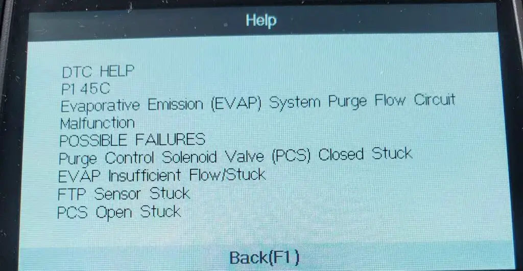
(Credit: crvownersclub.com)
Let’s explore briefly the EVAP system – The purpose of the EVAP system is to capture and manage fuel vapors generated in the fuel system. This system prevents fuel vapors from escaping into the environment. It includes components like the fuel tank, charcoal canister to trap vapors, purge valve, vent valve, sealed fuel filler cap, pressure sensors, and various lines.
The P145C code is commonly found in various Honda models, including but not limited to: Civic, Accord, CR-V, HR-V, Pilot, Odyssey, etc.
In some cases, the P145C code might be accompanied by other related codes that provide more information about the specific nature of the problem. These accompanying codes might include the following:
- P1456: Evaporative Emissions Control System Leakage (Fuel Tank System)
- P0443: Evaporative Emission Control System Purge Control Valve Circuit
- P0496: EVAP Flow During A Non-Purge Condition
- P0497: Evaporative Emission System Low Purge Flow
How Severe Is The P145C Code In Your Honda?
The P145C code found in Honda vehicles has a moderate severity level. It’s possible to drive, but short-term driving is allowed (within a range of 30 to 50 miles). Prolonged driving without addressing the issue could lead to increased emissions and reduced fuel efficiency.
It’s still recommended to have the issue addressed as soon as possible. Continuing to drive with a malfunctioning EVAP system can have negative effects on the environment and vehicle performance. After reaching your destination, consider scheduling a diagnostic check with a qualified technician. Timely repairs will prevent further complications and maintain the vehicle’s efficiency and emission control.
What Are The Signs Of The P145C Code On Honda Vehicles?
The presence of the “P145C” code in Honda vehicles is often accompanied by the following symptoms:
- Check Engine Light (MIL) illuminated
- Decreased fuel efficiency
- Increased emissions
- Difficulty starting the engine
- Engine stalling
What Are The Causes Of The P145C Honda Code?
There are various factors can trigger the P145C code in Honda vehicles, including:
- Malfunctioning evaporative emission canister vent shut valve
- Wiring or electrical connectivity problems within the EVAP system
- Defective evaporative emission canister purge valve
- Hose leaks or blockages in the EVAP system
- Corrosion or damage to relevant components
- Faulty fuel tank pressure sensor
- PCM issues
Read more: P1009 Honda Code: VTC System Troubleshooting And Solutions
How To Diagnose And Fix The P145C Code On Honda?
When your Honda vehicle displays the “P145C” code, addressing it promptly is crucial. This section outlines the essential tools, a step-by-step procedure, and estimated costs associated with diagnosing and repairing the issue:
Essential Tools And Parts
To diagnose and repair the “P145C” code effectively, ensure you have the following tools and parts at hand:
- OBD-II scanner
- Multimeter
- Wiring and connectors
- Replacement EVAP components (vent shut valve, purge valve) if necessary.
Step-by-Step Procedure
1. Retrieve Diagnostic Trouble Codes (DTCs)
Use the OBD-II scanner to retrieve the P145C code, additional codes and associated freeze frame data. This will help you pinpoint the exact issue within the EVAP system.
2. Visual Inspection Of Wiring And Connections
- Thoroughly inspect the wiring and connections related to the EVAP system for signs of damage, corrosion, or loose connections. Pay close attention to the wiring harnesses, connectors, and terminals.
- Address any issues found during this inspection.
3. Test Evaporative Emission Canister Vent Shut Valve And Purge Valve
- Using a digital multimeter, perform voltage and resistance tests on both the evaporative emission canister vent shut valve and the purge valve.
- Follow the manufacturer’s specifications for proper voltage and resistance values.
- Replace any valve that does not meet the specified values.
4. Check Hoses For Blockages Or Leaks
- Inspect all hoses within the EVAP system for blockages, kinks, or leaks. Ensure that hoses are properly connected and free from obstructions.
- Replace any damaged hoses to restore proper airflow within the system.
5. Fuel Tank Pressure Sensor Inspection
Examine the fuel tank pressure sensor for any signs of damage or malfunction.
6. Update PCM Software
- Check if there are any available software updates for the Powertrain Control Module (PCM) related to the EVAP system.
- If updates are available, follow the manufacturer’s instructions to update the PCM software. This can sometimes address compatibility issues and improve system performance.
- In case the PCM completely fails, find a skilled Honda mechanic nearby for replacement.
7. Clear The Codes And Test Drive
After conducting all procedures, clear the codes by using an OBD scanner. Then, perform a test drive to see if the codes come back or not.
Note:
- Make sure to save all the free data about the issue and any on-board snapshots.
- If any of the codes (P0496, P0497) appear along with P145C, start by fixing those codes, then check for P145C again. If both codes P0497 and P145C are stored together, inspect the line that connects the EVAP canister purge valve and the EVAP canister. Look for poor connections, blockages, or damage. Also, check if the EVAP canister purge valve is stuck closed.
Read more: Honda OBD2 Codes List [Generic + Manufacturer-specific]
DIY Repair Level And Estimated Costs
The repair procedure for the “P145C” code involves a moderate to advanced level of automotive expertise. Additionally, it requires diagnostic tools and component testing skills. If you’re confident in your abilities, you may attempt the repairs. However, if you’re unsure or inexperienced, seeking professional assistance is recommended to avoid complications.
Here’s an approximate cost breakdown for key tasks related to resolving the P145C code:
| Repair Task | Estimated Cost |
| Wiring and connector repair | $50 – $150 |
| EVAP vent shut valve replacement | $50 – $200 |
| EVAP canister purge valve replacement | $50 – $200 |
| EVAP system blockage or leak repair | $50 – $300 |
| Fuel tank pressure sensor | $100 – $250 |
| PCM software update or replacement | $100 – $1,500 |
Keep in mind that these costs can vary based on factors like your vehicle’s make and model, as well as your location. If you’re uncertain about any aspect of the repair process or lack experience, consulting a certified mechanic is a prudent step to ensure an effective and safe resolution of the issue.
P145C Honda Infographic

Final Thoughts
Facing the P145C code in your Honda vehicle might seem daunting, but armed with knowledge and guidance, you’re well-equipped to address the issue.
Remember, proper diagnosis and timely repairs are essential for maintaining optimal vehicle performance and minimizing emissions. Whether you’re a seasoned DIY enthusiast or prefer leaving it to the experts, taking action now ensures a smoother ride ahead.
If you found this guide helpful, share it with fellow Honda owners who might benefit.
Feel free to leave your comments and questions below – we’re here to assist you on your automotive journey. Safe travels and happy troubleshooting!
Reference Sources
- HONDA DTC CODES – page 6
- JustAnswer, 2007 Honda Truck Odyssey V6-3.5L
P0172: System Too Rich (Bank 1)
P0172: System Too Rich (Bank 1)
Was the P0172 code activated on your scan tool? Do you wonder whether it is dangerous to keep driving?
Read on to have a first evaluation of your situation!
- P0172 Definition: System Too Rich (Bank 1)
- Code Type: Generic – P0172 indicates the same problem whether you’re having a Chevy, Honda, or Toyota, etc.
- Can I drive with the P0172 code? Yes, but you should drive for a short period. Extending driving will cause more severe damage to your engine.
- Easy to fix? Beginner-Intermediate level.
- Cost: $30 – $280 (common)
Now, you know this code is not that dangerous.
If you don’t want to waste your money, let’s dive into 7 causes that might trigger the P0172 code and the corresponding solutions.
What Does The P0172 Code Mean?
P0172 is an OBD-II generic code triggered when the engine control unit (ECU) detects too much gasoline and not enough oxygen in the air-fuel mixture.
Further Explanation
The ECU monitors the engine’s air-fuel ratio through mass airflow sensor (MAF), oxygen sensors, and manifold absolute pressure (MAP).
The ideal air-fuel mixture (air-fuel ratio) is always following the rate of 14.7:1; 14.7 grams of air are required for every 1 gram of fuel. This specific ratio was chosen because of its highest power output but lowest fuel consumption rate.
When the air-fuel ratio goes below 14.7, the amount of fuel in the combustion chamber is much more than the oxygen.
This is called a “rich” mixture, and then the ECU triggers the P0172 code.
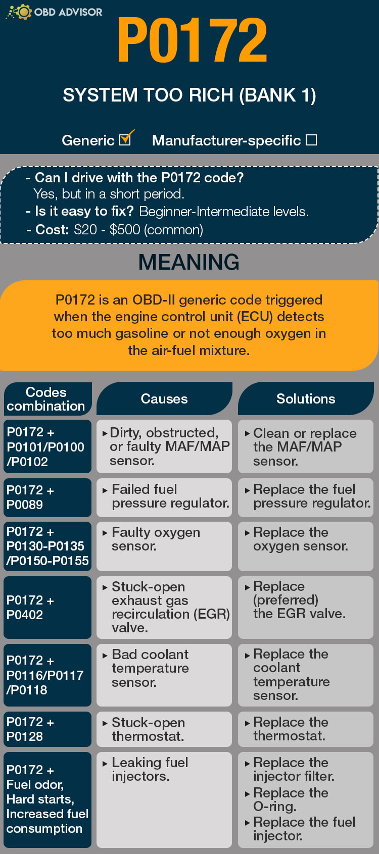
P0172 Causes Identification: Quick View
When your scanner tool displays the P0172 code, sometimes the screen will show another code following P0172.
Here is a detailed table helping you identify which one is the culprit and find out the solutions immediately.
| Codes Combination | Causes | Solutions |
|---|---|---|
| P0172 + P0101 /P0100/P0102 | Dirty, obstructed, or faulty MAF/MAP sensor. | Clean or replace the MAF/MAP sensor. |
| P0172 + P0089 | Failed fuel pressure regulator. | Replace the fuel pressure regulator. |
| P0172 + P0130-P0135 | Faulty oxygen sensor. | Replace the oxygen sensor. |
| P0172 + P0402 | Stuck-open exhaust gas recirculation (EGR) valve. | Replace (preferred) the EGR valve. |
| P0172 + P0116/P0117/P0118 | Bad coolant temperature sensor. | Replace the coolant temperature sensor. |
| P0172 + P0128 | Stuck-open thermostat. | Replace the thermostat. |
| P0172 + Fuel odor, Hard starts, Increased fuel consumption | Leaking fuel injectors. | Replace the injector filter. Replace the O-ring. Replace the fuel injector. |
Note: The causes for each code combination are the most common ones. There can be some uncommon issues hidden under those codes.
P0172: Causes, Symptoms, And How To Fix
Cause #1: Faulty MAF/MAP Sensor
The mass airflow (MAF) and manifold absolute pressure (MAP) sensor are essential to your car’s electronic fuel injection system.
Their function is to help the PCM determine the required fuel delivery for a perfect rate of 14.7:1.
You can find them near the engine’s intake manifold.
Over time, the MAF/MAP sensor can be contaminated for many reasons, such as dirt, air, and debris in the sensor.
That’s why they failed, leading to overstating the number of air flowing into the engine.
Hence, drivers should pay attention to any of the following symptoms in their vehicle’s performance:
- P0172 and P0101/P0100/P0102 code activated.
- Check engine light on.
- Black exhaust smoke.
- Rough idle.
- Poor fuel economy.
- Poor acceleration.
You can easily fix the P0172 code by cleaning the dirty MAF/MAP sensor or replacing it if the MAF/MAP sensor is faulty.
Cause #2: Faulty Fuel Pressure Regulator
A fuel pressure regulator regulates the fuel pressure (35-65 psi) going to the fuel injectors.
Suitable fuel pressure (air to fuel ratio) helps your vehicle run with maximized power and fuel economy. If the fuel regulator goes wrong, the fuel pressure is too high, resulting in a rich air-fuel ratio.
A ruptured diaphragm inside the regulator and a stuck closed regulator are two reasons causing a rich running condition.
If you notice these symptoms, your vehicle may have a bad fuel pressure regulator:
- A combination of P0172 and P0089 codes appeared.
- Poor engine performance.
- A fuel leak in the regulator’s vacuum line.
- Black smoke.
- Soot on spark plugs.
Replacing the fuel pressure regulator with a new one will solve this problem.
Cause #3: Faulty Oxygen Sensor
An oxygen sensor (upstream) is a device used to help the engine keep a specific air-fuel ratio that balances power, fuel economy, and emissions.
When the O2 sensor is defective, it might detect the wrong amount of air and send it back to the ECU, making the air-fuel ratio not follow the standard rate.
If you don’t want more damage to your car, take a look at these signs:
- P0172 and faulty O2 sensor codes (P0130-P0135) appeared.
- Check engine light on.
- Poor fuel efficiency.
- Smell and black smoke from the exhaust.
- “Lazy” O2 sensor voltage chart.
“Lazy” O2 Sensor Voltage Chart
Replacing a faulty oxygen sensor is an effective way to fix the P0172 code if it is the problem.
Cause #4: Stuck-Open EGR Valve
Exhaust Gas Recirculation (EGR) is a system used for reducing automotive nitrogen oxide (NOx) emissions.
It works by taking a small quantity of the exhaust gas back to the engine’s combustion chambers through the intake manifold.
After a long time, carbon deposits build-up inside the EGR valve, sticking it open.
The endless exhaust gas takes the air’s place, making the amount of air decrease dramatically. Consequently, the air-fuel ratio is not balanced anymore.
Stuck-open EGR will bring you a lot of bad situations, and you should look for these signs to clean or replace the EGR valve as soon as possible:
- P0172 and P0402 code triggered.
- Poor performance.
- Rough idle.
- Increased fuel consumption.
- Smell of exhaust gas.
- Engine knock.
- More emissions.
With a stuck-open EGR valve, it is recommended to replace it as the EGR valve is not too pricey.
If you have a low budget, try to clean the build-up inside with this video.
Cause #5: Bad Coolant Temperature Sensor
As evident from its name, an engine coolant temperature sensor (ECT) measures the engine coolant’s temperature.
An inaccurate coolant temperature can cause a rich condition because they will report that the engine is still cold, which will cause the PCM to keep the mixture rich long after the engine is at proper operating temperature.
Here are some significant symptoms of a faulty coolant temperature sensor:
- P0172 and P0116/P0117/P0118 codes activated.
- Check engine light on.
- Overheated engine.
- Poor fuel efficiency.
- Poor engine performance.
- Black smoke from the exhaust pipe.
In addition to these symptoms, you can take a small test to compare the coolant temperature with a thermal gun and the ECT’s temperature in the Live Data function. If the number on the thermal gun is different from the one on the scan tool (>190ºF), maybe your ECT sensor is broken down.
A coolant temperature sensor is not too expensive, you can erase this code from your car by replacing the ECT sensor.
Cause #6: Stuck-Open Thermostat


The engine thermostat is a valve that can open and close to let the coolant flow into the radiator, lowering the engine’s temperature.
A stuck-open thermostat can make your engine still cold and take more time to warm up. Therefore, your car’s engine may not be likely to reach proper operating temperature and need a richer fuel mixture, leading to more fuel than air.
To avoid any further damage, you should notice these obvious signs:
- A combination of P0172 and P0128 pops up.
- Long warm-up time.
- Lack of heat.
- Poor gas mileage.
It’s not easy to unstick the stuck-open thermostat as it seems. I suggest you should replace the thermostat with a new one since it’s inexpensive.
Cause #7: Leaking Fuel Injectors
Fuel injectors spray the fuel as mist into a car’s engine through a small nozzle.
Leaking fuel injectors appeared in older cars with high mileage. A fuel injector can leak due to two primary causes:
- The body of the injector
- The O-ring
When the fuel injector leaks, it will spray excess fuel in liquid form, not mist. Keeping the fuel injector leaking constantly will create a rich air-fuel mixture.
Be careful with these symptoms if they appear on your car:
- Hard starts.
- Fuel odor.
- Hesitation or shaking while idling.
- Increased fuel consumption.
- Increased exhaust.
- Thinning oil.
- Hydrolocking.
There are three ways you can use to fix the leaking fuel injectors, you can replace the injector filter, the injector O-ring, or the fuel injector itself.
How Much Does It Cost To Fix The Code P0172?
Repair and replacement costs to fix the P0172 code can vary a lot if you choose to fix it yourself or go to a mechanic shop.
For DIYers, it will cost you around $300 for the most expensive part.
If you can’t handle it on your own, you have to pay from $70-$500 for a mechanic.
The Estimated Repair Cost Of P0172
| Solutions | Cost |
|---|---|
| Clean MAF/MAP sensor | – DIY: $15 – Repair shop: $50 – $100 |
| Replace MAF/MAP sensor | – DIY: $30 – $200 – Repair shop: $80 – $280 |
| Replace the fuel pressure regulator | – DIY: $50 – $200 – Repair shop: $150 – $350 |
| Replace the injector filter | – DIY: $15 – $20 – Repair shop: $200 – $300 |
| Replace the injector O-ring | – DIY: $1 – $20 – Repair shop: $150 – $400 |
| Replace the fuel injector | – DIY: $70 – $280 – Repair shop: $200 – $500 |
| Replace (preferred) the EGR valve | – DIY: $190 – $270 – Repair shop: $250 – $350 |
| Replace the ECT sensor | – DIY: $20 – $80 – Repair shop: $70 – $330 |
| Replace the thermostat | – DIY: $20 – $80 – Repair shop: $140 – $300 |
| Replace the oxygen sensor | – DIY: $20 – $130 – Repair shop: $70 – $250 |
Note: The data in this table is collected in May 2022. The actual price depends on many factors, such as your car’s make and year, mechanic’s rate, etc.
You Ask, I Answer
Although the P0172 code is not that severe, it will bring you a lot of troubles, such as poor fuel economy, hard starts, and poor engine performance.
I hope this article will help you save your budget from visiting the mechanic.
Any other questions about P0172, don’t hesitate to leave a comment below, I’ll answer them all.
If you have had the same issue and fixed it before, share your story with us.
See ya!
Read more: The 9 Best OBD2 Scanners for 2024: The Only Review You Need
P0171: System Too Lean (Bank 1)
P0121 – Throttle/Pedal position sensor/switch “A” circuit
P0121 – Throttle/Pedal position sensor/switch “A” circuit
The P0121 code triggers when the “A” and “B” circuits of your vehicle’s throttle position sensor don’t match, which can be a severe problem, activating your car’s failsafe mode and limiting engine performance.
While the throttle position sensor failures are the most common cause of the P0121 trouble code, you don’t want to replace it. There may be issues with the wiring or more extensive electrical problems. Conducting a full diagnosis is essential to make sure the code doesn’t return.
In many cases, the P0121 trouble code can be quickly cleared in a home garage. Read on below to learn more about what causes it and how you can identify and eliminate the problem.
P0121 code definition
P0121 code definition (generic): Throttle position sensor/switch A circuit range/performance problem
P0121 Dodge code definition: Throttle Pos. Exceed (Short Time)
P0121 Ford code definition: (TP) sensor circuit performance problem
P0121 Nissan code definition: (TP) sensor circuit performance problem
P0121 Toyota code definition: Throttle Pedal Position Sensor/Switch “A” Circuit Range/Performance
What does P0121 mean?
The sensor that monitors your throttle’s movement is the throttle position sensor (TPS). This sensor is a potentiometer, measuring the current that passes through to indicate the throttle position. As the throttle opens, the voltage goes up.
The TPS circuit has a designated output voltage for both the “A” and the “B” circuit. This voltage is monitored by the engine control module (ECM) to make sure the throttle position is staying where it should be. The ECM also sends a 5-volt reference signal to the sensor. Usually, the sensor will measure around .5 volts when idling and as much as 4.5 volts when at full throttle.
The “A” and “B” circuits of the TPS sensor should maintain a particular relationship with each other. When the P0121 OBD2 code triggers, the ECM has detected a TPS “A” circuit voltage that’s either too high or too low compared to the “B” circuit.
P0121 is a generic powertrain code, so it applies to any vehicle equipped with OBD2. You may want to follow different steps for the diagnosis and repair depending on your vehicle manufacturer, however. Check for any technical service bulletins for this code for your vehicle.
What are the symptoms of the P0121 code?
When the P0121 trouble code activates, the engine will go into failsafe mode, limiting the throttle’s response, which prevents your car from driving above a certain speed. In addition to the failsafe mode, you’ll likely notice some of the following symptoms:
- Activation of the check engine light
- Knocking sounds in the engine
- Engine stalling or refusing to start
- Vehicle accelerating slowly
- Smoke in the exhaust when accelerating
- Engine stumbling and jerking when changing speeds
- Lower maximum speed
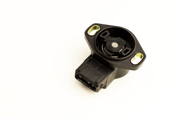
What are the causes of P0121?
- Open or short in TPS
- Open or short in the TPS wiring
- Faulty or loose connections on the TPS
- Corrosion or moisture in sensor connections
- Failed or faulty ECM (rare)
How serious is the P0121 code?
The P0121 trouble code is very severe. Only the activation of failsafe mode will make your car difficult to drive. It may also prevent your car from starting or lead to stalling if it does run. You should stop driving your vehicle when this code activates and fix the problem immediately.
How to diagnose and fix the P0121 code
Tools you’ll need:

Method:
- Scan the TPS data using an OBD2 scan tool. Compare the readings for circuit “A” and circuit “B.” If there’s a variance, check your manual for manufacturer tests for the TPS.
- Scan your system to see if any other trouble codes have been triggered. You may see other codes related to the throttle position sensor (P0120-P0124).
- Use the OBD2 scan tool to read the idle and wide-open throttle (WOT) readings. Compare them with the specifications in your vehicle’s manual. If they’re not, this indicates an issue with the TPS, wiring, or connectors.
- Visually inspect all the wiring and connections of the TPS system. Replace any wires that are damaged or corroded, and make sure all connections are secure. Also, inspect the TPS connections for corrosion or moisture damage. After your inspection, clear the codes and test drive your vehicle. If the code returns, continue with your diagnosis.
- Use an oscilloscope to check for an open or short in the signal sent by the TPS. The signal should go up and down smoothly. If you see sharp drops or spikes, the sensor should be replaced.
- Use a digital multimeter to check the reference voltage at the connector. It should read 5 volts. If it doesn’t, check the ground circuit. It may have an open or short. If the signal circuit reads 12 volts, trace the circuit to find the source of the short and repair it.
- If the code still doesn’t clear, take your vehicle to a mechanic for further diagnosis. In rare instances, the P0121 triggers because of a more serious electrical problem. A professional will be able to determine if this is the case.
Common mistakes to avoid while diagnosing the P0121 code
Many mechanics immediately replace the TPS before visually inspecting the system for corroded wires, loose connections, and other simple fixes. Make sure you conduct a full, thorough diagnosis before replacing any components. If the wiring is the problem, replacing the sensor won’t fix it.
Tips to avoid P0121 in the future
If the TPS wires aren’t installed carefully, they can rub against the wiring harness., which leads to damaged wires, one of the primary causes of the P0121 trouble code. Ensure the wires in your system aren’t touching anything that could damage them to prevent shorts and other electrical issues. Moisture also damages electrical components, like sensors. If you see signs of moisture on the TPS or its connections, figure out how it’s getting into your engine. Identifying and fixing the source of the leak will prevent future damage to the TPS.
Read more: P0335 Code: Meaning, Symptoms, Causes, Diagnostics, and Fixes
P1574 Nissan Code: Navigating Transmission Concerns
P1574 Nissan Code: Navigating Transmission Concerns
So, you’ve come across the P1574 code in your Nissan, and it’s left you wondering what’s gone awry. No need to panic – In this article, I’m here to help you decode its meaning.
I will walk you through the basics of the P1574 code, including why it’s popped up and what steps you can take to make it vanish. Buckle up, as I’m gonna clarify the P1574 code and get your Nissan back on track!
Let’s explore!
P1574 Nissan: A Quick Overview
Go through the P1574 Nissan code summary outlined below!
- Definition: ASCD Vehicle Speed Sensor
- Severity: Medium
- DIY Skill Level: Intermediate
- Continue To Drive?: No
- Estimated Repair Cost: $50 – $500
What Does The P1574 Code Mean In Nissan Vehicles?
The P1574 Nissan Diagnostic Trouble Code (DTC) indicates a problem with the Engine Control Module (ECM) receiving conflicting vehicle speed signals. The ECM receives two speed signals via the Controller Area Network (CAN) communication line. One signal is transmitted from the combination meter, while the other comes from the Transmission Control Module (TCM). These signals are crucial for the operation of the Automatic Speed Control Device (ASCD) system.
When the ECM detects inconsistent or conflicting speed signals, it triggers the P1574 DTC. This code serves as an indicator that there is a communication issue between the combination meter, TCM, and ECM, affecting the ASCD control functionality.
(Credit: maxima.org)
The P1574 trouble code is commonly found in various Nissan models. The following models usually get the P1574 code: Altima, Maxima, Sentra, Rogue, Murano, etc.
In some cases, the P1574 DTC may be accompanied by additional trouble codes. It is essential to address these associated codes before troubleshooting the P1574. The following are some common codes that may appear alongside P1574: Uxxxx (U code), P0500, P0605, P0607
It is important to diagnose and resolve any accompanying codes alongside the P1574 DTC to ensure a comprehensive repair process and restore proper vehicle functionality.
How Severe Is The P1574 Code In Nissan?
The severity level of the P1574 Nissan code can be considered moderate. While it does not present an immediate safety risk or major drivability issues, it is not advisable to continue driving with this code unresolved. Ignoring the P1574 DTC may result in the loss of cruise control functionality.
To ensure optimal vehicle performance and safety, it is recommended to address the code promptly. Therefore, seeking assistance from a qualified mechanic can help identify the cause and facilitate the necessary repairs or component replacements. Resolving the P1574 promptly restores the proper operation of the ASCD system, promoting a safer driving experience.
What Are The Signs Of The P1574 Code?
The P1574 Nissan code can manifest in various symptoms. If you are experiencing this code, you may notice one or more of the following:
- A malfunction indicator lamp (MIL) illuminated
- Loss of cruise control functionality
- Inconsistent or erratic speedometer readings
What Causes The P1574 Code in Nissan Vehicles?
The P1574 Nissan can be caused by various factors. Common causes of this code include:
- Low brake fluid
- Wiring or communication problems in the CAN network
- Faulty combination meter
- Bad wheel sensor(s)
- Malfunctioning ABS actuator and ABS control unit
- Issues with the TCM
- Faulty ECM
It’s important to note that these are potential causes, and a thorough diagnostic procedure is necessary to determine the underlying issue in your specific vehicle accurately.
Read more: P1777 Nissan Code: A Practical Repair Guide
How To Diagnose And Fix The P1574 Code In Your Nissan?
When your Nissan displays the P1574 code, think of it as your car’s way of telling you it’s having a problem. To tackle this, you’ll need certain tools and parts that are necessary. Following a set of steps in order is important, and you should also see if you can manage to fix it yourself. By sticking to these guidelines, you can increase your chances of successfully dealing with the P1574 code problem in your Nissan.
Essential Tools And Parts
To diagnose and repair the P1574 code, the following tools and parts may be required:
- OBD-II scanner
- Digital multimeter
- Brake fluid
- Wiring diagram
- Combination meter
- Wheel sensors
- ABS actuator and control unit
- TCM
- ECM
Step-by-Step Procedure
1. DTCs retrieval
Begin by connecting an OBD-II scanner to the vehicle’s OBD-II port. Then, retrieve and record all present DTCs, including the P1574 code.
2. Brake fluid inspection and refill
- Check the brake fluid level in the vehicle’s brake fluid reservoir.
- If the brake fluid is low, top it up to the recommended level. Use the type of brake fluid specified in the vehicle’s service manual.
3. Wiring and connection testings
- Inspect the wiring connections and harnesses of all the systems above. Look for any visible signs of damage, corrosion, loose connections, or frayed wires.
- Use a digital multimeter to check those connections, and consult the wiring diagram for your specific Nissan model.
- Compare the readings obtained to the specifications provided in the vehicle’s service manual.
- Repair or replace any damaged wiring as necessary.
4. Wheel sensor examination and replacement
- If the problem persists, inspect the wheel sensors.
- Clean the sensors and their mounting surfaces, and check for any damage or excessive debris.
- Replace any wheel sensors that are faulty, damaged, or contaminated.
5. ABS actuator and control unit diagnostic testing
- If the ABS actuator and its control unit are suspected to be the cause of the P1574 code, perform further diagnostic tests.
- This may involve using specialized diagnostic tools to assess the ABS actuator’s functionality and communication with the control unit.
- Follow the manufacturer’s instructions and guidelines for testing and diagnosing the ABS system.
6. Comprehensive system diagnostics for combination meter, TCM, and ECM
- If the issue still exists, perform specific tests and procedures outlined in the vehicle’s service manual to diagnose the combination meter, TCM, and ECM.
- Replace any faulty system if necessary.
- It’s advisable to get help from a professional mechanic to execute this step.
7. Clearing DTCs and final road test
Clear all DTCs using the diagnostic tool and conduct a road test to ensure the P1574 code does not reappear.
Read more: C1109 Nissan Code: ABS Voltage Trouble Exposed
DIY Repair Level And Estimated Costs
Diagnosing and repairing the P1574 Nissan code may require intermediate-level automotive diagnostic and repair skills. If you are unfamiliar with the diagnostic procedures or lack the necessary tools, it is advisable to seek assistance from a qualified mechanic or technician.
The cost of repairing the P1574 code can vary depending on the specific cause and the replacement parts required. Now, let’s have a look at an estimated cost breakdown for the primary repair tasks:
| Repair Task | Estimated Cost |
| Brake fluid change | $50 – $100 |
| Wheel speed sensor replacement | $50 – $200 per sensor |
| Wiring repair | $50 – $150 |
| ABS control module replacement | $200 – $500 |
| Combination meter replacement | $150 – $500 |
| TCM replacement | $200 – $800 |
| ECM replacement | $200 – $1000 |
Please be aware that these cost approximations are not fixed and can differ depending on elements like the type of vehicle, where you are located, and the charges for labor. In order to obtain accurate cost details specific to your vehicle, it is recommended to consult with a mechanic or obtain personalized quotes.
P1574 Nissan Infographic
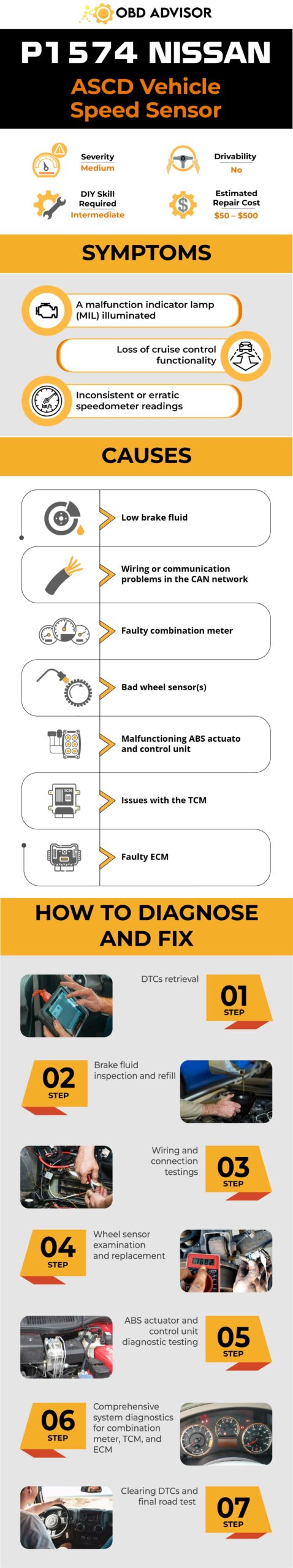
Final Thoughts
In conclusion, understanding the P1574 code and its implications in the ABS system is crucial for maintaining optimal braking performance and vehicle safety. If you encounter challenges or lack expertise, it is advisable to seek assistance from a qualified professional.
Stay proactive in addressing ABS system concerns to ensure a safe and reliable driving experience. Stay informed, drive safely, and don’t hesitate to share this valuable information with others. And, drop a comment below if you have any questions. Safe driving!
Learn more about other codes by using our OBD lookup tool!
Reference Sources
- NiAltima, P1574 ASCD vehicle speed sensor
- AUTONERDZ, Maxima ECM reprogramming data
- J.D. Power, What is a front-wheel speed sensor?
P0014 – “B” Camshaft Position – Timing Over-Advanced or System
P0014 – “B” Camshaft Position – Timing Over-Advanced or System
The P0014 OBD2 code tells you the timing of your engine is off. It specifically points you to the B camshaft on bank 1, making this code easier to diagnose than many OBD2 trouble codes. This code can typically be fixed by replacing a valve or solenoid. It may also be an indication that you’re using the wrong kind of oil. Read on to find out how to diagnose and repair this code correctly.
P0014 Code Definition
P0014 Code Definition (Generic): “B” Camshaft position – timing over-advanced or system performance (Bank 1)
P0014 Equinox (Chevy) Code Definition: Camshaft Position B – Over Advanced – Bank 1 (common)
P0014 Hyundai Code Definition: Camshaft Position B – Over Advanced – Bank 1 (common)
P0014 Kia Code Definition: “B” Camshaft position timing over-advanced
P0014 Peugeot Code Definition: “B” Camshaft position timing over-advanced
P0014 Trailblazer (Chevy) Code Definition: Camshaft Position B – Over Advanced – Bank 1 (common)
What Does P0014 Mean?
The P0014 OBD2 code indicates that the timing of your exhaust camshaft is too advanced. Your engine doesn’t operate the same way all the time. The engine control unit varies the valves’ timing, pistons, and other components depending on how much the engine is revving. Each component has an associated sensor that sends information to the ECU. The ECU then uses this data to determine when to power certain systems and how much power to send them. The goal is to keep the engine running as smoothly and efficiently as possible, with minimal emissions. If the ECU detects that the B camshaft on bank 1 has advanced more than it should, the P0014 trouble code will activate. Bank 1 is the side of the engine that contains cylinder 1. Depending on your vehicle, the B camshaft could be called the rear camshaft, the right camshaft, or the exhaust camshaft.
What Are The Symptoms Of The P0014 Code?
The symptoms of this code can change based on the position of the camshaft when it became over-advanced. Some common symptoms include:
- Activation of the check engine light
- Engine is hard to start
- Engine idles rough or stalls while idling
- Increased fuel consumption
- Increase in harmful emissions
What Are The Causes Of P0014 OBD2 Code?
Two systems could be the origin point of P0014: The camshaft and its components or the oil system. Specific causes include:
- Failure of camshaft variable timing solenoid
- Bad timing in camshaft
- Faulty wiring in the intake timing system
- Stuck or faulty camshaft phaser
- Short in the oil control solenoid
- Excessive oil viscosity
- Clogged passages around the camshaft phasers
How Serious Is The P0014 OBD2 Code?
The drivability issues associated with P0014 can cause further damage to your engine if allowed to go on for too long. While it is not unsafe to drive with this code active, you should repair it as soon as possible to avoid additional complications.
How To Diagnose The P0014 OBD2 Code
More often than not, the P0014 OBD2 code results from a mechanical failure in your engine. You should check your vehicle’s manual for suggestions before beginning your diagnosis. This trouble code often has specific fixes depending on what kind of car you drive.
Tools You’ll Need:
Method:
- Scan your system for other trouble codes. If you detect related trouble codes like P0010, P0011, P0012, P0020, P0021, or P0022, diagnosing those could help you identify the specific problem.
- Inspect the wiring and solenoids around the oil control valve and bank 1 B camshaft. Replace any that are frayed or damaged, and ensure all connections are secure.
- Check the level and viscosity of your oil. Your vehicle’s manual should contain information on the correct viscosity for your system.
- Use an OBD2 scan tool to read the live freeze frame data for the bank 1 B camshaft. Disconnect the oil control valve connected to the camshaft. If the valve is functional, the data should change. If it doesn’t, the valve should be replaced.
- Find the cam phaser and inspect it for sludge or damage. Also, inspect the oil passages around the camshaft phasers for build-up.
Common Mistakes To Avoid While Diagnosing The P0014 OBD2 Code
Some people replace their sensors before checking to see if there’s a mechanical problem. P0014 is rarely electrical in nature. Run a full diagnosis before you replace any components.
What Should You Do To Fix The P0014 OBD2 Code?
Use an OBD2 scan tool to clear the trouble codes after each repair, then conduct a test drive to see if they recur. While this might seem tedious, it will prevent you from making unnecessary fixes and is the best way to identify the root cause definitively.
- Replace any damaged wires or solenoids found in your diagnosis.
- If your oil is old, dirty, or too thick, you should replace it. Drain the oil, then replace the oil filter. If you noticed deposits clogging the oil passages, flush the system before adding new oil.
- Replace the cam phaser if it’s dirty or damaged.
- Replace the oil control valve if it failed the freeze-frame test in step 4 of the diagnosis.
- If none of these fixes clear the code, the problem is likely an electrical malfunction in the engine control unit. Take your vehicle to a mechanic for further diagnosis.
Tips To Avoid P0014 OBD2 Code In The Future
More often than not, this problem is the result of a dirty engine. The best way to avoid problems with your camshaft timing is to prevent sludge and other deposits from accumulating in the first place. You can take a few easy steps to keep your engine clean:
- Drive your engine hard. Getting your engine hot is the best way to remove deposits from your system. This naturally happens if you do a lot of fast driving, so engine build-up is more common for cars mostly driven in cities. When your engine starts feeling sluggish, go out on the highway and push your engine harder than usual for a few miles.
- Use the right oil. A high-quality oil of the correct viscosity will keep your system running its best.
- Replace your oil regularly. The older your oil, the less effective it is at lubricating your system. Any dirt or debris in the oil can also stick to components and clog them. Make sure to change your oil as soon as your car is due.
Read more: P0303 Code: Meaning, Symptoms, Causes, Diagnostics, and Fixes
P2002 – Diesel particulate filter efficiency below threshold
P2002 – Diesel particulate filter efficiency below threshold
The P2002 code applies to diesel engines. They contain an additional filter to remove soot and contaminants from the exhaust. This limits harmful emissions and allows your vehicle to meet state standards.
The activation of P2002 indicates the inefficient filtering of your exhaust. This problem can be intermittent, and in some cases, will go away on its own with no driver intervention. You shouldn’t ignore it if it does stick around, though, as this affects both the environment and your engine’s performance.
Certain driving conditions and vehicles are more likely to activate the P2002 trouble code than others. Read on below to learn what you should do if this code triggers in your car or truck.
P2002 Code Definition (Generic): Diesel Particulate Filter Efficiency Below Threshold Bank 1
What does P2002 mean?
This code relates to diesel engines made in 2007 and later. These vehicles use an emission control device to lower the soot content of the exhaust. It does this by heating the engine enough to burn off pollutants, with an additional reductant catalyst to start the process.
The diesel particulate filter (DPF) removes about 98% of the soot in the exhaust when functioning correctly. If the emission control system has been activated, but the particulates in the exhaust don’t burn off, the P2002 trouble code activates.
When the DPF is in operation, it generates backpressure. Pressure feedback sensors allow the engine control module (ECM) or powertrain control module (PCM) to monitor its operation. A discrepancy in the pressure limits indicates there’s an issue with the filter.
While this code is a generic powertrain code, applicable to any diesel engine, the specific fixes can vary depending on your make and model. P2002 is most common in Dodge, Chevy, Ford, and GMC pickups. It can also trigger diesel cars, such as those made by Audi, Lexus, and VW.
This code is similar to P2003. The difference is P2002 relates to bank 1 of your engine, while P2003 points to bank 2. Bank 1 is the side of the engine that contains cylinder 1.
P2002 is what is considered a “soft code.” This means it reports an issue in real-time and can clear itself if the fault is corrected. If this happens once, you don’t need to worry about it. Repeated instances of P2002 warrant diagnosis. You should also consider repairs if the code does not turn itself off after a completed drive cycle.
What are the symptoms of the P2002 code?
The check engine light may stay illuminated with P2002, or it may come on intermittently. In many cases, there are no drivability issues associated with this code. If there are symptoms, they include:
- The activation of the check engine light
- Reduced fuel economy
- Sluggish acceleration
- Diluted oil
What are the causes of P2002?
- Fouled or faulty DPF.
- The exhaust back pressure sensor is faulty.
- Leaks in the exhaust system.
- Fuel quality is too low for the engine.
- The engine is not reaching high enough speeds/temperatures.
- Aftermarket components are not suitable for vehicles.
- The air cleaner element is dirty.
- Faulty PCM/ECM or components.
How serious is the P2002 code?
The P2002 trouble code is moderately severe. Although you may not experience drivability issues, your engine may go into failsafe mode if you don’t clear the code. Because of this, it’s essential to find the source of the issue as soon as possible.
How to diagnose and fix the P2002 code
Tools you’ll need: OBD2 scan tool
- Use an OBD2 scan tool to read the codes. If other codes are present, fix those first.
- If you mostly drive in a city or at low speeds, your engine may not be reaching high enough temperatures to burn off the soot. Take your car for a hard drive. Ensure you get at least 55 miles per hour for 20-30 minutes, then reduce speed quickly. Clear the codes and rescan with the OBD2 scan tool.
- If you have recently modified your vehicle, replace it with the original part. Certain modifications, including cat-back exhaust kits or cold air intake kits, can trigger this code. You can also check with the manufacturer to see if this is a known issue for your vehicle.
- Check for loose connections around the bank 1 DPF. Also, check for any burnt or loose wires, and make sure there’s no corrosion on the connectors.
- Look for exhaust leaks around the DPF. Pay close attention to the ends and connections, making sure everything is connected securely.
- Verify that you’re using fuel that is the correct quality for your engine. The fuel that contains too much sulfur leads to clogs in the DPF. Consult your manual if you’re not sure what the ideal diesel quality is for your engine.
- Check the DPF for dirt and clogs. In some cases, these filters may become too fouled to clear with a hard drive. Replace the filter, then clear the codes and test drive your vehicle.
- Should the code still not clear, take your car to a mechanic for further diagnosis. Advanced scan tools like the Tech II can determine if there is an issue with the ECM or PCM.
Common mistakes to avoid while diagnosing the P2002 code
If the issue causing the P2002 trouble code is a fouled filter, it may be a temporary problem. Make sure you take a test drive, reaching at least 55 miles per hour before replacing any components. DPF filters generally last a long time, so don’t assume the filter is failing until you’ve checked for other issues.
Tips to avoid P2002 in the future
Wires touching the DPF can be burnt and damaged by the high temperatures generated. Ensure all of the wires for the sensor are positioned away from engine components that could damage them.
If you drive mostly at low speeds, P2002 could be a recurring problem. You may want to consider taking your vehicle to a mechanic for a modification. They can reprogram the computer and remove the PDF, solving the issue.
Read more: P2096 Code: Meaning, Symptoms, Causes, Diagnostics, And Fixes
P0304 – Cylinder 4 misfire detected
P0304 – Cylinder 4 misfire detected
The cylinders in your engine are what provide its power. When they don’t fire correctly, your car will drive rough and be at risk for further damage. The P0304 OBD2 code is your first warning sign of misfires in your engine.
The P0304 code can be severe, so it’s not one you want to ignore. Read on below to learn more about what it means and how you can correctly diagnose it.
P0304 code definition
P0304 Code Definition (Generic): Cylinder 4 misfire detected
P0304 BMW: “Misfiring Of Cylinder 4, Damages TWC”
P0304 Dodge: Cylinder 1-10 Misfire Detected
P0304 Honda: Cylinder 4 Misfire Detected
P0304 Nissan: Cylinder #4 Misfire Detected
P0304 Subaru: #4 Cylinder Miss Fire
What does P0304 mean?
The cylinders provide the power in your engines. This is where the spark plugs ignite the air/fuel mixture, generating the energy that turns the crankshaft. A misfire occurs when there isn’t enough fuel burning in a cylinder.
When the engine functions correctly, the cylinders fire in sequence to provide continuous power to the crankshaft. If the RPM of the crankshaft changes by more than 2%, this is when the engine will trigger the P0304 code.
The P0304 OBD2 code explicitly indicates a misfire in cylinder 4. You can use your car’s manual to locate this cylinder. It is common to also see P0300 and other misfire-related codes as well with P0304.
What are the symptoms of the P0304 code?
You will often experience serious drivability problems when the P0304 trouble code activates. These include:
- The check engine light activates. If the light is solid, the change in the crankshaft RPMs is between 2% and 10%. A flashing or blinking light indicates a variance over 10%.
- The engine runs rough. The engine may shake while idling. You may also notice jerking or hesitation from the engine while accelerating.
- There’s difficulty starting or failure to start.
- There’s a smell of fuel in the exhaust.
- Engine power reduces.
- Fuel economy reduces.
What are the causes of P0304?
The most common causes of the P0304 trouble code are:
- Faulty or worn-out spark plugs
- Faulty wires around the spark plugs
- Faulty spark plug coils
- Failure of the distributor
- Faulty fuel injector
Engine misfires can also be a result of:
- Leaks in the vacuum system
- Fuel pressure is too low
- Timing issues in the engine
- Defective sensors (camshaft, crankshaft, oxygen, MAF, etc.)
- Leaking head gasket
- Fuel is too low quality for the engine
How serious is the P0304 code?
The P0304 OBD2 code is severe. Repeated misfires can damage your catalytic converter, ignition system, and other parts of your engine. The erratic performance also makes your vehicle a potential safety hazard. Stop driving your car when this code triggers, and refrain from driving until you’ve repaired the problem.
How to diagnose the P0304 code
Tools you’ll need:
- OBD2 scan tool
- Screwdriver and socket set
- Digital multimeter
- Fuel pressure gauge
- Compression tester
- Leakdown tester
- Scan your system for other OBD2 trouble codes. Fix any that come up other than P0300-P0308.
- Inspect the wires around the spark plugs for damage and loose connections.
- If your engine has individual coil packs, switch the cylinder 4 pack with the one in cylinder 1. Clear the codes and test drive your car. If the misfire jumps to cylinder 1, the pack is faulty and should be replaced.
- Visually inspect the spark plug for carbon build-up or other signs of fouling. It’s easiest to see if you have a new spark plug for comparison. Remove and clean the spark plug. If the build-up can’t be removed, replace the spark plug. A spark plug that’s shiny or blackened likely indicates the fuel mix is too rich.
- Use a multimeter to measure the resistance of the spark plugs. Replace the wires if the reading is higher than 15,000 ohms.
- Check the ignition coils. Remove the coil and touch the multimeter leads to both the primary and secondary ignition circuit. The primary ignition circuit typically reads between .4 and 2 ohms, and the secondary circuit between 6,000 and 10,000 ohms. Your vehicle’s manual can give you a more exact specification. If you get a 0 reading, the coil has an internal short.
- Use a fuel pressure gauge to test the fuel pressure. Compare the reading to the specifications in your vehicle’s manual.
- Unplug the fuel injector from your engine and probe the terminals with a multimeter. Compare the resistance reading to the specifications in your manual. A variance could indicate a faulty fuel injector.
- Perform both an engine compression test and a leak down test. Mechanical problems like worn valve guides, burned valves, skips in the timing chain, and broken valve springs or pistol rings can lead to misfires. These tests will identify any failing components.
Common mistakes to avoid while diagnosing the P0304 code
Ensure you don’t overlook small issues, like loose connections and vacuum leaks. Be thorough in your engine inspection to make sure you’ve caught every potential source of the misfire.
What should you do to fix the code P0304?
If you’re not experiencing any symptoms, clear the code and test drive your vehicle. A single misfire may not indicate long-term problems. If the code does come back, continue with the steps below.
- Replace any damaged wires found in your inspection, as well as any other components that failed diagnosis. Ensure all newly-installed items are functioning and all connections are secure.
- Check the EGR system and fuel injectors for clogs. Clean out any that you find.
- Test the sensors in your fuel and exhaust systems, including the crankshaft sensor, camshaft sensor, mass airflow sensor, and oxygen sensors. Inspect them visually for dirt or damage, then use a multimeter to ensure they’re receiving a charge. Replace any that are damaged.
Tips to avoid P0304 in the future
Issues with your air-to-fuel ratio may cause misfires. Check all the hoses in your system for leaks as part of your regular preventative maintenance. Air that gets into your system can make your air/fuel mix too lean. Alternatively, oil or carbon build-up on the spark plugs indicates a mix that’s too rich.
Using the wrong fuel can also cause engine misfires. More expensive fuel isn’t always the answer. Only use the grade recommended for your engine in your vehicle’s manual.
P1777 Nissan Code: A Practical Repair Guide
P1777 Nissan Code: A Practical Repair Guide
Dealing with a P1777 code in your Nissan can be frustrating. Do not fret! – In this guide, we’ll walk you through simple steps to tackle the issue. We’ll cover needed tools, explain the repair process, and discuss DIY feasibility.
This empowers both DIYers and those seeking professional help to make informed decisions and potentially save on repairs.
Let’s find out!
P1777 Nissan Code: A Quick Overview
Check the summary of the P1777 Nissan code below!
- Definition: Step Motor Circuit
- Severity: Medium
- DIY Skill Level: Intermediate
- Continue To Drive?: Yes
- Estimated Repair Cost: $20 – $200
What Is The Meaning Of The P1777 Nissan Code?
The P1777 Nissan code is a manufacturer-specific trouble code for Nissan vehicles. It indicates a specific concern within the step motor circuit of the automatic transmission. This code is triggered when any of the coils in the step motor fail to energize correctly, often due to an open circuit or a short circuit issue. While the vehicle might remain drivable with this code present, it highlights a potentially significant problem in the transmission system.
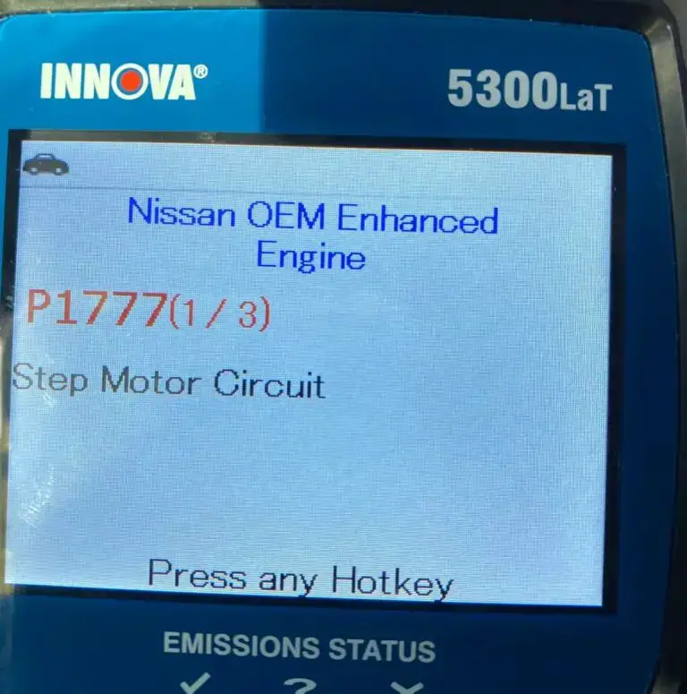
(Credit: nissanclub.com)
The step motor, also called a stepper motor, is crucial for converting pulsing electrical currents into controlled parts rotation. This helps control different mechanical parts within Nissan transmissions effectively.
This part operates through a unique mechanism involving the activation and deactivation of four coils. These coils are turned on and off based on signals received from the Transmission Control Module (TCM). By accurately translating electrical signals into these controlled movements, the step motor ensures the smooth operation and efficiency of the transmission system in Nissan vehicles.
The P1777 code has been reported in various Nissan models, potentially affecting the transmission performance across the following vehicles: Altima, Sentra, Maxima, Rogue (2009), Murano, Pathfinder, Versa (2007), Juke, Cube, etc.
How Severe Is Code P1777 Nissan?
The severity of the P1777 code in Nissan vehicles can be classified as moderate. It may be possible to continue driving the vehicle.
While driving at a safe speed might be viable, it’s important to understand that ignoring the code could result in further damage to the transmission over time. This could lead to issues like harsh shifting and delayed gear engagement, potentially affecting the vehicle’s drivability and overall performance. It’s recommended to address the issue promptly to ensure the vehicle’s safety and longevity by consulting a professional mechanic and seeking necessary repairs.
What Are The Symptoms Of The P1777 Nissan Codes?
The P1777 code in Nissan vehicles can manifest through various noticeable symptoms, indicating potential issues with the step motor circuit. Common symptoms include:
- Harsh or erratic shifting
- Delayed gear engagement
- Poor transmission performance
- Weak acceleration
- Check engine light illuminated
Read more: P1715 Nissan Code: Tips For Dealing With Transmission Issues
What Are The Causes Of The P1777 Nissan Code?
The P1777 code can arise due to several underlying causes. Possible factors include:
- Faulty step motor (stepper motor)
- Wiring or connector issues in the step motor circuit
How To Diagnose And Fix The P1777 Nissan Code?
When you encounter the P1777 code in your Nissan vehicle, it’s important to follow a clear process for diagnosis and repair. Here’s a simple breakdown of the tools and a step-by-step guide you need, along with a discussion of whether it’s a DIY job and how much it might cost:
Essential Tools And Parts
To diagnose and repair the P1777 code, you will likely need the following tools and parts:
- OBD-II scanner
- Multimeter
- Screwdrivers and wrenches
- Replacement step motor (if needed)
- Wiring repair kit (if addressing circuit issues)
Step-by-Step Procedure
- Inspect the wiring: Check the wiring and connectors around the step motor for damage or corrosion. Address any wiring or connector issues as needed
- Test the step motor: Use a multimeter to test the step motor’s resistance and functionality.
- Test the circuit: Check the circuit for continuity and voltage using the multimeter. And then fix it if necessary
- Replace step motor: If the step motor is found faulty, replace it with a new or tested working one.
- Clear codes: After repairs, clear the codes using the OBD-II scanner and test-drive the vehicle to ensure the issue is resolved.
Note:
- Tips: Consult the vehicle’s repair manual for specific testing procedures and values.
- Caution: Ensure safety precautions when working with electrical components.
Read more: Nissan Trouble Codes: Comprehensive List For OBD1/OBD2
DIY Repair Level And Estimated Costs
The diagnosis and repair of the P1777 code involve moderate complexity and require a good understanding of automotive systems. If you possess technical skills, you can attempt this repair. However, if uncertain, it’s advisable to consult a professional mechanic.
Here’s a general cost overview for potential repair tasks that may arise during the process:
| Repair Task | Estimated Cost Range |
| Replacement step motor (if needed) | $50 – $200+ |
| Wiring repair kit (if needed) | $20 – $50 |
| Mechanic labor (if seeking professional help) | $100 – $200+ |
Keep in mind that these costs can vary based on factors such as location, vehicle model, and the source of parts. If unsure about the repair process or the issue at hand, it’s recommended to consult a qualified mechanic for a proper diagnosis and resolution.
P1777 Nissan Infographic
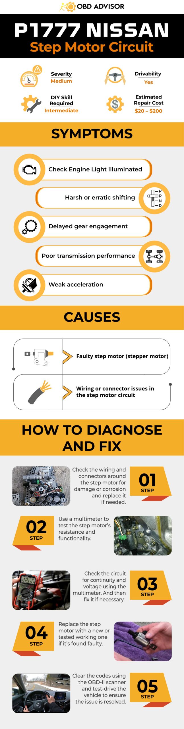
Final Thoughts
It is essential to equip yourself with good knowledge before popping the hood. This article has provided you, as a professional or even DIY enthusiast, with a good insight into P1777 on Nissan vehicles. Remember to address this issue to ensure the optimal performance of your Nissan.
Share your journey, questions, and insights in the comments below. If this information proves valuable, share it with fellow enthusiasts. Keep the road ahead smooth and the repairs purposeful!
Reference Sources
- Nissan Altima Service Manual, P1777 Step Motor – Nissan Altima – Automatic Transmission (Section TM)
- JustAnswer, P1777 Step Motor PDF – JustAnswer – Questions
P0138: O2 Sensor Circuit High Voltage (Bank 1, Sensor 2)
P0138: O2 Sensor Circuit High Voltage (Bank 1, Sensor 2)
Did your scan tool show the P0138 code? Do you wonder what it means and whether you can continue to drive?
Keep reading to have a first evaluation of the situation.
- P0138 Definition: O2 sensor circuit high voltage (Bank 1, Sensor 2)
- Code Type: Generic – P0138 indicates the same problem whether you’re having a Jeep, Toyota, or Dodge etc.
- Can I drive with the P0138 code? Yes, but keep driving will cause internal engine damage.
- Easy to fix? Intermediate level.
- Cost: $20 – $95 (common)
Luckily, P0138 is safe to drive in a short period!
But to avoid more harm to the engine, let’s read on to know the causes and how to fix these problems!
What Does The P0138 Code Mean?
The P0138 is triggered when the downstream O2 sensor (bank 1) voltage is too high (>1.2 volts) for more than 10 seconds. This high voltage indicates that the oxygen level in the exhaust gas is abnormally low.
What Is The O2 Downstream Sensor’s Function?
Downstream oxygen sensors (located after the catalytic converter) monitor the conditions of the catalytic converter.
The less air in the exhaust gas (after passing the cats), the higher the downstream O2 sensor’s output voltage.
Because the catalytic converter already processed the exhaust gas, the oxygen level is stable. Therefore, a normal working downstream O2 sensor stays around 0.45 volts.
What Can Trigger The P0138 Code?
The sensor voltage being too high can be explained by two scenarios:
- The reading is incorrect – results from the sensor’s wiring harness or the sensor itself
- The reading is correct – results from rich conditions
I’ll explain the details in the below parts.
But first, let’s navigate your cause.
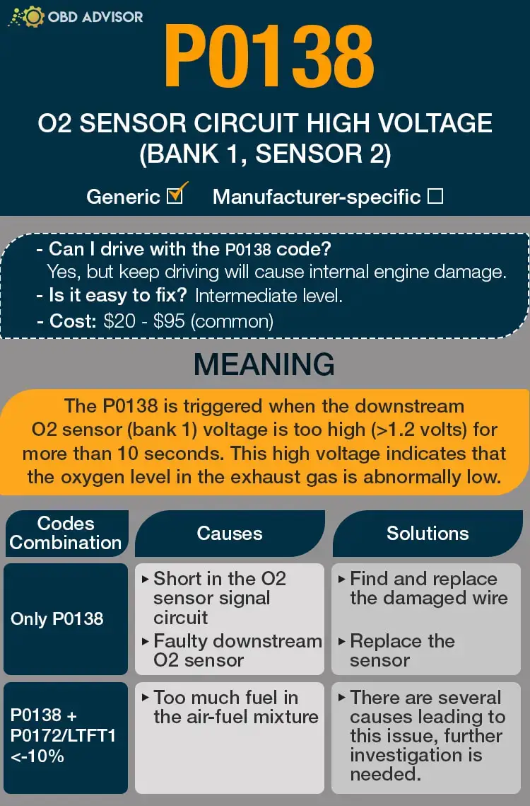
P0138 Causes Identification: Quick View
P0138 can appear alone or with other related codes. This table will help you navigate the root causes as well as the solutions for them.
| Codes Combination | Causes | Solutions |
|---|---|---|
| Only P0138 | Short in the O2 sensor signal circuit Faulty downstream O2 sensor | Find and replace the damaged wire Replace the sensor |
| P0138 + P0172/LTFT1<-10% | Too much fuel in the air-fuel mixture | There are several causes leading to this issue, further investigation is needed. |
Note: The causes for each code combination are the most common ones. There can be some uncommon issues hidden under those codes.
P0138: Causes, Symptoms, and How to Fix
Now, you may have a general idea of what causes the P0138 error code.
Read on to learn how to pinpoint the root problem and stop being a part-changer!
Cause #1: Short In The O2 Sensor Signal Circuit
This is the first thing you need to check.
Short to battery voltage in the O2 sensor signal circuit will make the sensor’s output voltage increase, triggering P0138.
If the wiring is the problem, there is no symptom other than the Check Engine Light. This is because downstream O2 sensors are not used to adjust the air-fuel ratio (like upstream.)
And there will be no effect on the engine performance.
Cause #2: Faulty Downstream O2 Sensor
After making sure all the wiring is good, a faulty downstream sensor is very likely to be the cause of P0138.
Again, there will be no symptoms in this case.
How to fix it?
All you have to do is to replace the sensor.
Bank 1 sensor 2 is located right after the catalytic converter. The replacement process is straightforward and the part itself is inexpensive. So, you can totally do it by yourself.
Tips: You will need a hammer and a wrench to break the sensor loose.
Cause #3: Rich Condition
A rich condition indicates that there is more than enough fuel in the air-fuel mixture,
This leads to a very low level of oxygen level in the exhaust gas, causing the computer to set P0138.
Symptoms of rich conditions causing P0138:
- Poor fuel economy
- Smell of gasoline
- Slow acceleration
- Negative long-term fuel trim on bank 1 (LTFT1<-10%)
- Combination of P0138 and P0172
There are many different causes that can lead to this condition.
How to know which problem your car is having?
First, you need to monitor the long-term fuel trim on both bank 1 (LTFT1) and bank 2 (LTFT2.)
- If Both LTFT1 and LTFT2 < -10%, the fuel pressure is too high (which is usually caused by bad FPR, fuel pump, fuel rail, etc.)
- If LTFT<-10% and -5%<LTFT2<5%, a sensor (on bank 1) is causing rich mixture (upstream O2 sensor, MAF, MAP, IAT, etc.)
After all, rich conditions causing P0138 are not something you should worry about. Most of the time, replacing an inexpensive sensor will fix the problem. The hard part is to know which one needs to be replaced.
For further diagnosis, I wrote an article about the code P0172. Read it and you can exactly pinpoint your problem!
How Much Does It Cost To Fix The Code P0138?
9 out of 10 times, you can just spend less than 100 bucks to fix the issues related to the bank 1 downstream O2 sensor.
If you get negative long-term fuel trim (rich conditions,) there can be many different solutions depending on the causes.
The Estimated Repair Cost Of P0138
| Solutions | Cost |
|---|---|
| Repair O2 sensor circuit | DIY: $10 – $20 Mechanic: $130 – $140 |
| Replace (downstream or upstream) O2 sensor | DIY: $20 – $95 Mechanic: $100 – $450 |
| Replace MAF/MAP sensor | DIY: $30 – $200 Mechanic: $80 – $280 |
| Replace the IAT sensor | DIY: $20-$150 Mechanic: $40-$250 |
| Repair IAT sensor wiring | DIY: $0-$20 Mechanic: $20-$75 |
| Replace the fuel pressure regulator (FPR) | DIY: $50 – $200 Mechanic: $150 – $350 |
| Replace the fuel pump | DIY: $50 – $850 Mechanic: $220 – $1,100 |
Note: The data in this table was collected in July 2022. The actual price depends on many factors, such as your car’s make and year, mechanic’s rate, etc.
You Ask, I Answer
Through this article, you will find it easier to identify the causes and the corresponding solutions to avoid more unnecessary expenses.
So, did you find out the reason causing P0138 on your car? Please leave a comment below.
And if you successfully erase this code by another way, don’t hesitate to share us your method. I am looking forward to know your ideas.
See ya!
Read more: The 9 Best OBD2 Scanners for 2024: The Only Review You Need
P0304 – Cylinder 4 misfire detected
P0304 – Cylinder 4 misfire detected
The cylinders in your engine are what provide its power. When they don’t fire correctly, your car will drive rough and be at risk for further damage. The P0304 OBD2 code is your first warning sign of misfires in your engine.
The P0304 code can be severe, so it’s not one you want to ignore. Read on below to learn more about what it means and how you can correctly diagnose it.
P0304 code definition
P0304 Code Definition (Generic): Cylinder 4 misfire detected
P0304 BMW: “Misfiring Of Cylinder 4, Damages TWC”
P0304 Dodge: Cylinder 1-10 Misfire Detected
P0304 Honda: Cylinder 4 Misfire Detected
P0304 Nissan: Cylinder #4 Misfire Detected
P0304 Subaru: #4 Cylinder Miss Fire
What does P0304 mean?
The cylinders provide the power in your engines. This is where the spark plugs ignite the air/fuel mixture, generating the energy that turns the crankshaft. A misfire occurs when there isn’t enough fuel burning in a cylinder.
When the engine functions correctly, the cylinders fire in sequence to provide continuous power to the crankshaft. If the RPM of the crankshaft changes by more than 2%, this is when the engine will trigger the P0304 code.
The P0304 OBD2 code explicitly indicates a misfire in cylinder 4. You can use your car’s manual to locate this cylinder. It is common to also see P0300 and other misfire-related codes as well with P0304.
What are the symptoms of the P0304 code?
You will often experience serious drivability problems when the P0304 trouble code activates. These include:
- The check engine light activates. If the light is solid, the change in the crankshaft RPMs is between 2% and 10%. A flashing or blinking light indicates a variance over 10%.
- The engine runs rough. The engine may shake while idling. You may also notice jerking or hesitation from the engine while accelerating.
- There’s difficulty starting or failure to start.
- There’s a smell of fuel in the exhaust.
- Engine power reduces.
- Fuel economy reduces.
What are the causes of P0304?
The most common causes of the P0304 trouble code are:
- Faulty or worn-out spark plugs
- Faulty wires around the spark plugs
- Faulty spark plug coils
- Failure of the distributor
- Faulty fuel injector
Engine misfires can also be a result of:
- Leaks in the vacuum system
- Fuel pressure is too low
- Timing issues in the engine
- Defective sensors (camshaft, crankshaft, oxygen, MAF, etc.)
- Leaking head gasket
- Fuel is too low quality for the engine
How serious is the P0304 code?
The P0304 OBD2 code is severe. Repeated misfires can damage your catalytic converter, ignition system, and other parts of your engine. The erratic performance also makes your vehicle a potential safety hazard. Stop driving your car when this code triggers, and refrain from driving until you’ve repaired the problem.
How to diagnose the P0304 code
Tools you’ll need:
- OBD2 scan tool
- Screwdriver and socket set
- Digital multimeter
- Fuel pressure gauge
- Compression tester
- Leakdown tester
- Scan your system for other OBD2 trouble codes. Fix any that come up other than P0300-P0308.
- Inspect the wires around the spark plugs for damage and loose connections.
- If your engine has individual coil packs, switch the cylinder 4 pack with the one in cylinder 1. Clear the codes and test drive your car. If the misfire jumps to cylinder 1, the pack is faulty and should be replaced.
- Visually inspect the spark plug for carbon build-up or other signs of fouling. It’s easiest to see if you have a new spark plug for comparison. Remove and clean the spark plug. If the build-up can’t be removed, replace the spark plug. A spark plug that’s shiny or blackened likely indicates the fuel mix is too rich.
- Use a multimeter to measure the resistance of the spark plugs. Replace the wires if the reading is higher than 15,000 ohms.
- Check the ignition coils. Remove the coil and touch the multimeter leads to both the primary and secondary ignition circuit. The primary ignition circuit typically reads between .4 and 2 ohms, and the secondary circuit between 6,000 and 10,000 ohms. Your vehicle’s manual can give you a more exact specification. If you get a 0 reading, the coil has an internal short.
- Use a fuel pressure gauge to test the fuel pressure. Compare the reading to the specifications in your vehicle’s manual.
- Unplug the fuel injector from your engine and probe the terminals with a multimeter. Compare the resistance reading to the specifications in your manual. A variance could indicate a faulty fuel injector.
- Perform both an engine compression test and a leak down test. Mechanical problems like worn valve guides, burned valves, skips in the timing chain, and broken valve springs or pistol rings can lead to misfires. These tests will identify any failing components.
Common mistakes to avoid while diagnosing the P0304 code
Ensure you don’t overlook small issues, like loose connections and vacuum leaks. Be thorough in your engine inspection to make sure you’ve caught every potential source of the misfire.
What should you do to fix the code P0304?
If you’re not experiencing any symptoms, clear the code and test drive your vehicle. A single misfire may not indicate long-term problems. If the code does come back, continue with the steps below.
- Replace any damaged wires found in your inspection, as well as any other components that failed diagnosis. Ensure all newly-installed items are functioning and all connections are secure.
- Check the EGR system and fuel injectors for clogs. Clean out any that you find.
- Test the sensors in your fuel and exhaust systems, including the crankshaft sensor, camshaft sensor, mass airflow sensor, and oxygen sensors. Inspect them visually for dirt or damage, then use a multimeter to ensure they’re receiving a charge. Replace any that are damaged.
Tips to avoid P0304 in the future
Issues with your air-to-fuel ratio may cause misfires. Check all the hoses in your system for leaks as part of your regular preventative maintenance. Air that gets into your system can make your air/fuel mix too lean. Alternatively, oil or carbon build-up on the spark plugs indicates a mix that’s too rich.
Using the wrong fuel can also cause engine misfires. More expensive fuel isn’t always the answer. Only use the grade recommended for your engine in your vehicle’s manual.
P026A Code: Causes & Solutions for Charge Air Cooler Issues
P026A Code: Causes & Solutions for Charge Air Cooler Issues
Got a P026A DTC (diagnostic trouble code)? Don’t panic. This expert guide can help you understand the code and get it fixed with ease.
So, what does the code P026A mean? Simply put, it indicates that the Charge Air Cooler is not working as effectively as expected.
If you’re curious to learn more about this DTC and how it can affect your vehicle’s performance, read on. In this article, we will provide you with valuable insights and practical solutions to address this issue effectively. Let’s dive in!
P026A Code: An Overview
Here are the main highlights of the P026A code.
- Definition: Charge Air Cooler Low Efficiency
- Severity: Medium
- DIY Skill Level: Intermediate
- Continue To Drive?: Yes
- Estimated Repair Cost: $50 – $300
P026A Meaning: What Does It Signify?
The P026A code is an indication that the charge air cooler (CAC) efficiency in your vehicle has fallen below the threshold. This code is commonly triggered in cars equipped with Powerstroke and Cummins engines, such as Ford, RAM, and some VW models.
Let’s explore the systems and components involved to understand this code better. The charge air cooler, also known as the intercooler, is responsible for cooling down the compressed air from the turbocharger before it enters the engine’s intake manifold. It is crucial in optimizing the engine’s performance and fuel efficiency.
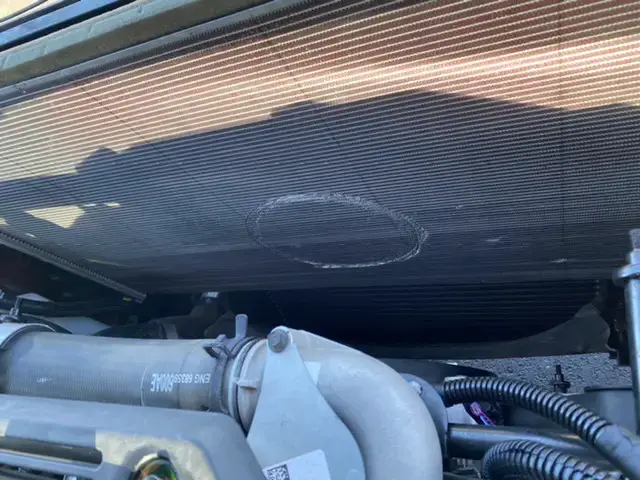
(Image credit: Cummins Forum)
In the case of Cummins engines, the Powertrain Control Module (PCM) compares the reading from the CAC Temperature Sensor to a calibrated threshold. The calibrated threshold varies based on the Ambient Air Temperature Sensor reading. If the CAC Temperature Sensor reading remains above the calibrated threshold for a cumulative total of 120 seconds, the PCM determines that the CAC is operating inefficiently, triggering the code P026A.
For Ford vehicles, the PCM sets the P026A code when it identifies that the measured CAC efficiency doesn’t match the expected efficiency, and this difference lasts for at least 10 seconds.
How Serious Is The P026A Code?
The P026A code is considered a medium severity. While it is generally safe to continue driving with this code, addressing the underlying issue promptly is crucial to avoid potential complications.
An inefficient CAC can lead to reduced engine performance and fuel efficiency. It can also place additional strain on other engine components if left unresolved. Therefore, it is recommended to have the issue diagnosed and repaired as soon as possible to restore optimal performance and prevent further damage.
Read more: Ford OBD2 Codes List for FREE Download
Note: In some cases, the P026A code may appear when towing and disappear when not towing. If you attempt to clear the code and it reappears only during towing without noticeable driveability concerns, it is generally safe to disregard it. However, it’s still important to monitor the situation and promptly address any related issues if they arise.
P026A Symptoms: Signs Of An Inefficient CAC
The P026A DTC may present the following symptoms:
- Reduced engine performance
- Decreased fuel efficiency
- Engine hesitation or rough idle
- Illuminated check engine light
P026A Causes: Uncovering The Culprits
The P026A code can be caused by various factors, including:
- Low CAC coolant level
- Restrictions or blockages in the CAC, including the fins
- Faulty CAC temperature sensor
- Faulty cooling fan
Read more: P0118: Engine Coolant Temperature Sensor Circuit High Input
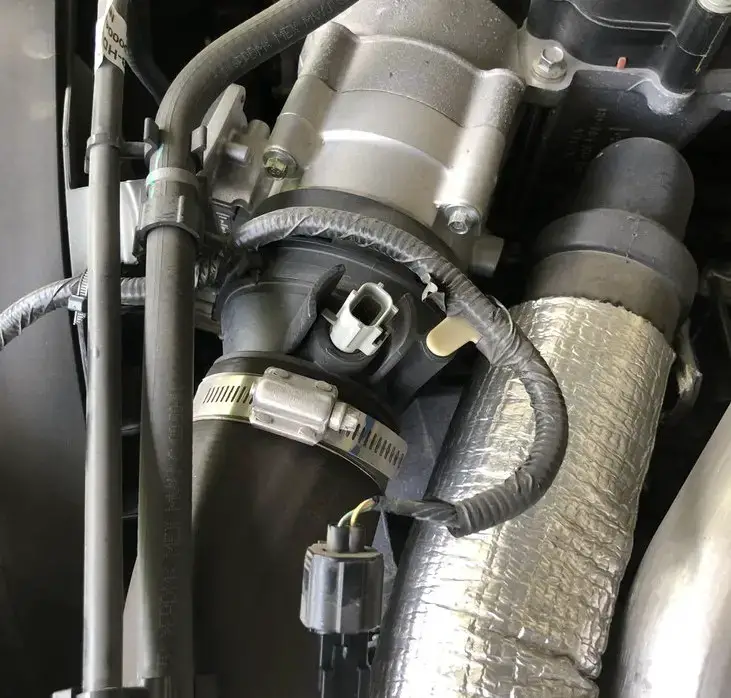
Step-by-Step Diagnosis And Repair For P026A
Let’s make resolving the P026A code a breeze! Our step-by-step diagnosis and repair process will guide you smoothly through the entire procedure.
Essential Tools And Parts
- Diagnostic scan tool
- Multimeter
- Coolant level checker
- Inspection mirror
- Cooling system pressure tester
- Replacement CAC temperature sensor
- Replacement cooling fan
Step-by-step Procedure
Step 1: Scan for DTCs
Start by using a diagnostic scan tool to retrieve the P026A and any accompanying codes. Note down the DTCs for reference during the repair process.
Step 2: Check and top off the coolant level
Inspect the coolant level in the charge air cooler. If low, add the appropriate coolant and check for leaks.
Step 3: Address CAC restrictions or blockages
- Examine the CAC for any restrictions or blockages. Clear any debris or obstructions from the CAC fins using compressed air or a vacuum cleaner.
- Remove the grill and clean the radiators if the CAC fins are blocked. Use compressed air or a vacuum cleaner to remove debris from the backside, then hose off with water from the front.
- Check the coolant lines connected to the CAC for any restrictions, cracks, or misrouting. Replace or repair any damaged lines as necessary.
Step 4: Verify cooling fan functionality
Check the cooling fan for proper operation. If the fan is faulty, replace it to ensure adequate cooling.
Step 5: Test the CAC temperature sensor
Verify the functionality of the CAC temperature sensor using a multimeter. If the sensor is faulty, replace it with a new one.
Step 6: Clear codes and test drive
Clear the codes and conduct a test drive to evaluate the vehicle’s performance.
Note: Please ensure to follow safety precautions and refer to specific vehicle manufacturer instructions for detailed guidance during the repair process.
DIY Repair Level And Estimated Costs
The repair procedure for P026A can vary in complexity. In general, it’s recommended for people who have intermediate automotive knowledge and skills.
If you are comfortable working on your vehicle’s cooling system and have the necessary tools, you may be able to tackle this repair on your own. However, if you are unsure or unfamiliar with these procedures, you should seek assistance from a professional mechanic.
Here is an estimated cost breakdown for the main repair tasks:
| Repair Task | Estimated Cost |
| CAC cleaning and repair | $30 – $100 |
| Coolant lines repair/replacement | $20-$50 |
| CAC temperature sensor replacement | $50-$300 |
| Cooling fan replacement | $100-$400 |
Remember that these are rough estimates, and actual costs may vary depending on the vehicle model, labor rates, and location.
Final Thoughts
In conclusion, addressing the P026A DTC is essential to restore your vehicle’s optimal performance and prevent further damage. You can effectively diagnose and repair the issue by following the step-by-step procedure outlined in this guide and utilizing the necessary tools.
We hope this guide has provided valuable insights and practical solutions to resolve the P026A code. If you found this information helpful, please share it with others.
Stay smooth and happy driving!
Reference Sources
- Vestas Aircoil A/S, Charge Air Coolers Explained.
- Dura-Light, Charge Air Cooler Leaks: The Basics.
- ScienceDirect, Diagnosis Of Clogged Charge Air Cooler Faults In A Diesel Engine Using Singular Spectrum Analysis.
P0011 – “A” camshaft position – Timing over-advanced or system
P0011 – “A” camshaft position – Timing over-advanced or system
The P0011 OBD2 code tells you the timing is off on your “A” camshaft. When this happens, it’s most often caused by a problem with the oil viscosity. It can also result from a solenoid failure or stuck valve, however, so you want to do your due diligence and check the system thoroughly before making repairs.
The fix for the P0011 is often specific to a vehicle’s make and model. Your manual will also outline the correct oil viscosity for your system, so that’s the first thing you should find when the P0011 trouble code activates.
Issues with your engine timing can quickly snowball into more severe problems, so you’ll want to fix this trouble code as soon as you notice it. Read on below to find out how to properly diagnose and repair this problem.
P0011 code definition
- P0011 code definition (generic): “A” Camshaft position – timing over-advanced or system performance (Bank 1)
- P0011 Chevy code definition: Intake camshaft position system performance
- P0011 Kia code definition: “A” camshaft position timing over-advanced or system performance bank 1
- P0011 Nissan code definition: Intake valve timing control performance bank 1
- P0011 Subaru code definition: Camshaft position “A” timing over-advanced or performance bank 1
- P0011 Toyota code definition: Camshaft position “A” timing over-advanced or system performance bank 1
- P0011 VW code definition: “A” camshaft position timing over-advanced or system performance bank 1
What does P0011 mean?
Generally speaking, you can interpret the P0011 OBD2 code to mean your intake camshaft’s timing is off. The engine doesn’t operate at the same level the entire time you’re driving. The timing of the valves is varied by the ECU in response to the engine’s RPM range.
When P0011 activates, it tells you the “A” camshaft in bank 1 is in a more advanced position than it should be, which is the camshaft that’s at the intake, which could be the left or the front camshaft, depending on your vehicle.
Properly diagnosing and fixing the P0011 code doesn’t just mean returning it to the proper position at the moment but also discovering what caused the timing error in the first place. That part of the process can sometimes be tricky, depending on your vehicle and the reason for the trouble code.
What are the symptoms of the P0011 code?
You will usually notice drivability issues when the P0011 code activates. These symptoms include:
- Activation of the check engine light,
- The engine is hard to start,
- The engine runs rough or hesitates,
- Reduced gas mileage,
- Increase in harmful emissions,
- Stalling.
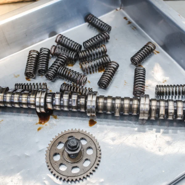
What are the causes of P0011?
- Faulty wiring around intake timing control valve system,
- Failure of camshaft variable timing solenoid,
- Seized camshaft phaser,
- Incorrect oil viscosity,
- Oil flow to the variable camshaft timing chamber is continuous.
How serious is the P0011 code?
The P0011 code is moderately serious. The rough driving caused by this trouble code can lead to further engine damage if you don’t address it promptly. While you can drive for a little while with this code active, you should repair the problem as soon as possible.
How to diagnose the P0011 code
Diagnosis and repair of the P0011 trouble code can vary depending on your vehicle’s make and model. Before you start your diagnosis, read your vehicle’s service manual. You can also check for released technical service bulletins related to this trouble code.
Tools you’ll need:
Method:
- Check for other trouble codes, specifically related codes like P0010, P0012, P0021, or P0022. If these are present, they can help you to hone in on the cause of your problem.
- Inspect the wiring and valves around the bank 1 exhaust valve and oil control valve.
- Make sure that all electrical connections within the system are secure and unimpeded.
- Check the oil. Make sure it’s at the right level, and inspect the viscosity. If it seems too thick or too thin, replace the oil. You can find the specifications for the correct oil viscosity in your vehicle’s manual.
- Check the timing chain alignment to see if it’s jumped, which could be causing your engine’s timing problems.
- Use an OBD2 scan tool to read the freeze frame data. Watch the live data while you disconnect the oil control valve on the exhaust camshaft. The data should change. If it does, the valve is functioning correctly. If it doesn’t, you may have a more serious electrical problem with your engine control module, which is rare, however, as this trouble code more often points to a mechanical issue.
Common mistakes to avoid while diagnosing the P0011 code
Don’t assume the problem is with the sensor without checking the systems themselves. Ensure that you conduct a full diagnosis and identify the problem’s actual cause before buying any new components.
What should you do to fix the code P0011?
After each step in your repair, clear the trouble codes and then take a test drive. If you’re still having symptoms or the code recurs, continue with the next step of the diagnosis. Avoid replacing any components until you’ve confirmed the problem isn’t something simple.
- Replace any damaged wires you find around the bank 1 exhaust system.
- Drain your oil, even if you don’t see any issue with the viscosity. Replace the oil filter and flush your system, then replace it with fresh oil.
- Check the camshaft variable timing solenoid. If it’s damaged, replace it.
- Check the camshaft oil control valve for the bank 1 intake camshaft to see if it’s damaged or stuck open. If you notice faults or problems, replace the valve.
- If none of these fixes clear the code, the issue may be electrical. Take your car to a mechanic for further diagnosis.
Tips to avoid P0011 in the future
The best thing you can do to avoid the P0011 trouble code is to change your oil regularly and check it for problems in between oil changes. Issues with your oil viscosity can cause issues beyond the timing of the camshaft.
You should always use the oil viscosity recommended by the manufacturer. The oil system components are designed to a specific size for a particular kind of fluid to flow through them. The oil, too thick or too thin, won’t move through the system the way it’s supposed to.
Read more: P0507 Code: Meaning, Symptoms, Causes, Diagnostics, and Fixes.
Land Rover Fault Codes: A Complete List For Free Download
Land Rover Fault Codes: A Complete List For Free Download
Are Land Rover fault codes leaving you puzzled and in search of answers?
Fret no more. This guide has compiled an extensive collection of OBD1 and OBD2 codes specific to Land Rover models. Whether you’re a seasoned DIY enthusiast or a professional mechanic, this resource will give you the clarity to diagnose issues confidently.
Don’t hesitate, and let’s begin our exploration!
Land Rover OBD1 Codes List And Definition [FULL]
Free download: Full Land Rover OBD1 Trouble Codes List and Meaning PDF
Note: Use the search box in the table below to quickly find the specific code you’re looking for.
| Code | Definition |
|---|---|
| Code 2 | Battery Recently Disconnected |
| Code 3 | ECM Memory Recently Cleared |
| Code 12 | MAF Sensor |
| Code 14 | ECT Sensor |
| Code 15 | Engine Fuel Temperature Sensor |
| Code 17 | Throttle Position Sensor |
| Code 18 | Throttle Position Sensor/Mass Air Flow Sensor |
| Code 19 | Throttle Position Sensor/Mass Air Flow Sensor |
| Code 21 | Fuel Tune Select Resistor |
| Code 23 | Fuel Supply |
| Code 25 | Ignition Misfire |
| Code 28 | Air Leak |
| Code 29 | ECM Memory Check |
| Code 34 | Injector Bank A |
| Code 36 | Injector Bank B |
| Code 40 | Misfire Left Bank |
| Code 44 | HO2S Left Bank |
| Code 45 | HO2S Right Bank |
| Code 48 | Idle Air Control Valve |
| Code 50 | Misfire Right Bank |
| Code 59 | Group Faults 23/28 |
| Code 68 | Vehicle Speed Sensor |
| Code 69 | Park/Neutral Position Switch |
Powertrain Land Rover OBD2 Codes List And Definition [FREE DOWNLOAD]
Free download: Full Nissan OBD2 Trouble Codes List and Meaning PDF
Note: Use the search box in the table below to quickly find the specific code you’re looking for.
| Code | Definition |
|---|---|
| P0100 | Mass or Volume Air Flow Circuit Malfunction |
| P0101 | Mass Air Flow Sensor Signal Error Fault |
| P0101 | Mass or Volume Air Flow Circuit Range/Performance Problem |
| P0102 | Mass Air Flow Sensor Low Out of Range Fault |
| P0102 | Mass or Volume Air Flow Circuit Low Input |
| P0103 | Mass Air Flow Sensor High Out of Range Fault |
| P0103 | Mass or Volume Air Flow Circuit High Input |
| P0104 | Mass or Volume Air Flow Circuit Intermittent |
| P0105 | Manifold Absolute Pressure/Barometric Pressure Circuit Malfunction |
| P0106 | Manifold Absolute Pressure/Barometric Pressure Circuit Range/Performance Problem |
| P0107 | Manifold Absolute Pressure/Barometric Pressure Circuit Low Input |
| P0108 | Manifold Absolute Pressure/Barometric Pressure Circuit High Input |
| P0109 | Manifold Absolute Pressure/Barometric Pressure Circuit Intermittent |
| P0109 | Intake Air Temperature Circuit Malfunction |
| P0110 | IAT Circuit Malfunction |
| P0111 | Air Temperature Sensor Signal Error Fault |
| P0111 | Intake Air Temperature Circuit Range/Performance Problem |
| P0112 | Air Temperature Sensor Low Out of Range Fault |
| P0112 | Intake Air Temperature Circuit Low Input |
| P0113 | Air Temperature Sensor High Out of Range Fault |
| P0113 | Intake Air Temperature Circuit High Input |
| P0114 | Intake Air Temperature Circuit Intermittent |
| P0115 | Engine Coolant Temperature Circuit Malfunction |
| P0116 | Engine Coolant Temperature Sensor Falling Temp Fault |
| P0116 | Engine Coolant Temperature Circuit Range/Performance Problem |
| P0117 | Engine Coolant Temperature Sensor Low Out of Range Fault |
| P0117 | Engine Coolant Temperature Circuit Low Input |
| P0118 | Engine Coolant Temperature Sensor High Out of Range Fault |
| P0118 | Engine Coolant Temperature Circuit High Input |
| P0119 | Engine Coolant Temperature Circuit Intermittent |
| P0120 | Throttle Position Sensor/Switch A Circuit Malfunction |
| P0121 | Throttle Position Sensor Output Signal Error Fault |
| P0121 | Throttle Position Sensor/Switch A Circuit Range/Performance Problem |
| P0122 | Throttle Position Sensor Low Out of Range Fault |
| P0122 | Throttle Position Sensor/Switch A Circuit Low Input |
| P0123 | Throttle Position Sensor High Out of Range Fault |
| P0123 | Throttle Position Sensor/Switch A Circuit High Input |
| P0124 | Throttle Position Sensor/Switch A Circuit Intermittent |
| P0125 | Engine Coolant Temp Sensor Warm Up Fault |
| P0125 | Insufficient Coolant Temperature for Closed Loop Fuel Control; ECT Excessive Time to Closed Loop Fuel Control |
| P0126 | Insufficient Coolant Temperature for Stable Operation |
| P0128 | Coolant Thermostat Malfunction |
| P0130 | Oxygen Sensor Cycle Fault *Codes* A U |
| P0130 | O2 Sensor Circuit Malfunction (Bank 1 Sensor 1) |
| P0131 | Oxygen Sensor Low Voltage *Codes* A U |
| P0131 | O2 Sensor Circuit Low Voltage (Bank 1 Sensor 1) |
| P0132 | Oxygen Sensor High Voltage *Codes* A U |
| P0132 | O2 Sensor Circuit High Voltage (Bank 1 Sensor 1) |
| P0133 | Oxygen Sensor Slow Response *Codes* A U |
| P0133 | O2 Sensor Circuit Slow Response (Bank 1 Sensor 1) |
| P0134 | O2 Sensor Circuit No Activity Detected (Bank 1 Sensor 1) |
| P0135 | O2 Sensor Heater Circuit Malfunction (Bank 1 Sensor 1) |
| P0136 | Oxygen Sensor Cycle Fault *Codes* A D |
| P0136 | O2 Sensor Circuit Malfunction (Bank 1 Sensor 2) |
| P0137 | Oxygen Sensor Low Voltage *Codes* A D |
| P0137 | O2 Sensor Circuit Low Voltage (Bank 1 Sensor 2) |
| P0138 | Oxygen Sensor High Voltage *Codes* A D |
| P0138 | O2 Sensor Circuit High Voltage (Bank 1 Sensor 2) |
| P0139 | Oxygen Sensor Slow Response *Codes* A D |
| P0139 | O2 Sensor Circuit Slow Response (Bank 1 Sensor 2) |
| P0140 | O2 Sensor Circuit No Activity Detected (Bank 1 Sensor 2) |
| P0141 | O2 Sensor Heater Circuit Malfunction (Bank 1 Sensor 2) |
| P0142 | O2 Sensor Circuit Malfunction (Bank 1 Sensor 3) |
| P0143 | O2 Sensor Circuit Low Voltage (Bank 1 Sensor 3) |
| P0144 | O2 Sensor Circuit High Voltage (Bank 1 Sensor 3) |
| P0145 | O2 Sensor Circuit Slow Response (Bank 1 Sensor 3) |
| P0146 | O2 Sensor Circuit No Activity Detected (Bank 1 Sensor 3) |
| P0147 | O2 Sensor Heater Circuit Malfunction (Bank 1 Sensor 3) |
| P0150 | Oxygen Sensor Cycle Fault *Codes* B U |
| P0150 | O2 Sensor Circuit Malfunction (Bank 2 Sensor 1) |
| P0151 | Oxygen Sensor Low Voltage *Codes* B U |
| P0151 | O2 Sensor Circuit Low Voltage (Bank 2 Sensor 1) |
| P0152 | Oxygen Sensor High Voltage *Codes* B U |
| P0152 | O2 Sensor Circuit High Voltage (Bank 2 Sensor 1) |
| P0153 | Oxygen Sensor Slow Response *Codes* B U |
| P0153 | O2 Sensor Circuit Slow Response (Bank 2 Sensor 1) |
| P0154 | O2 Sensor Circuit No Activity Detected (Bank 2 Sensor 1) |
| P0155 | O2 Sensor Heater Circuit Malfunction (Bank 2 Sensor 1) |
| P0156 | Oxygen Sensor Cycle Fault *Codes* B D |
| P0156 | O2 Sensor Circuit Malfunction (Bank 2 Sensor 2) |
| P0157 | Oxygen Sensor Low Voltage *Codes* B D |
| P0157 | O2 Sensor Circuit Low Voltage (Bank 2 Sensor 2) |
| P0158 | Oxygen Sensor High Voltage *Codes* B D |
| P0158 | O2 Sensor Circuit High Voltage (Bank 2 Sensor 2) |
| P0159 | Oxygen Sensor Slow Response *Codes* B D |
| P0159 | O2 Sensor Circuit Slow Response (Bank 2 Sensor 2) |
| P0160 | O2 Sensor Circuit No Activity Detected (Bank 2 Sensor 2) |
| P0161 | O2 Sensor Heater Circuit Malfunction (Bank 2 Sensor 2) |
| P0162 | O2 Sensor Circuit Malfunction (Bank 2 Sensor 3) |
| P0163 | O2 Sensor Circuit Low Voltage (Bank 2 Sensor 3) |
| P0164 | O2 Sensor Circuit High Voltage (Bank 2 Sensor 3) |
| P0165 | O2 Sensor Circuit Slow Response (Bank 2 Sensor 3) |
| P0166 | O2 Sensor Circuit No Activity Detected (Bank 2 Sensor 3) |
| P0167 | O2 Sensor Heater Circuit Malfunction (Bank 2 Sensor 3) |
| P0170 | Fuel Trim Malfunction (Bank 1) |
| P0171 | Oxygen Sensor System Too Lean Fault Bank A |
| P0171 | Fuel Trim System Lean (Bank 1) |
| P0172 | Oxygen Sensor System Too Rich Fault Bank A |
| P0172 | Fuel Trim too Rich (Bank 1) |
| P0173 | Fuel Trim Malfunction (Bank 2) |
| P0174 | Oxygen Sensor System Too Lean Fault Bank B |
| P0174 | Fuel Trim too Lean (Bank 2) |
| P0175 | Oxygen Sensor System Too Rich Fault Bank B |
| P0175 | Fuel Trim too Rich (Bank 2) |
| P0176 | Fuel Composition Sensor Circuit Malfunction |
| P0177 | Fuel Composition Sensor Circuit Range/Performance |
| P0178 | Fuel Composition Sensor Circuit Low Input |
| P0179 | Fuel Composition Sensor Circuit High Input |
| P0180 | Fuel Temperature Sensor A Circuit Malfunction |
| P0181 | Fuel Temperature Sensor Signal Error Fault |
| P0181 | Fuel Temperature Sensor A Circuit Range/Performance |
| P0182 | Fuel Temperature Sensor Low Out of Range Fault |
| P0182 | Fuel Temperature Sensor A Circuit Low Input |
| P0183 | Fuel Temperature Sensor High Out of Range Fault |
| P0183 | Fuel Temperature Sensor A Circuit High Input |
| P0184 | Fuel Temperature Sensor A Circuit Intermittent |
| P0185 | Fuel Temperature Sensor B Circuit Malfunction |
| P0186 | Fuel Temperature Sensor B Circuit Range/Performance |
| P0187 | Fuel Temperature Sensor B Circuit Low Input |
| P0188 | Fuel Temperature Sensor B Circuit High Input |
| P0189 | Fuel Temperature Sensor B Circuit Intermittent |
| P0190 | Fuel Rail Pressure Sensor Circuit Malfunction |
| P0191 | Fuel Rail Pressure Sensor Circuit Range/Performance |
| P0192 | Fuel Rail Pressure Sensor Circuit Low Input |
| P0193 | Fuel Rail Pressure Sensor Circuit High Input |
| P0194 | Fuel Rail Pressure Sensor Circuit Intermittent |
| P0195 | Engine Oil Temperature Sensor Malfunction |
| P0196 | Engine Oil Temperature Sensor Range/Performance |
| P0197 | Engine Oil Temperature Sensor Low |
| P0198 | Engine Oil Temperature Sensor High |
| P0199 | Engine Oil Temperature Sensor Intermittent |
| P0200 | Injector Circuit Malfunction |
| P0201 | Injector 1 Circuit Fault |
| P0201 | Injector Circuit Malfunction – Cylinder 1 |
| P0202 | Injector 2 Circuit Fault |
| P0202 | Injector Circuit Malfunction – Cylinder 2 |
| P0203 | Injector 3 Circuit Fault |
| P0203 | Injector Circuit Malfunction – Cylinder 3 |
| P0204 | Injector 4 Circuit Fault |
| P0204 | Injector Circuit Malfunction – Cylinder 4 |
| P0205 | Injector 5 Circuit Fault |
| P0205 | Injector Circuit Malfunction – Cylinder 5 |
| P0206 | Injector 6 Circuit Fault |
| P0206 | Injector Circuit Malfunction – Cylinder 6 |
| P0207 | Injector 7 Circuit Fault |
| P0207 | Injector Circuit Malfunction – Cylinder 7 |
| P0208 | Injector 8 Circuit Fault |
| P0208 | Injector Circuit Malfunction – Cylinder 8 |
| P0209 | Injector Circuit Malfunction – Cylinder 9 |
| P0210 | Injector Circuit Malfunction – Cylinder 10 |
| P0211 | Injector Circuit Malfunction – Cylinder 11 |
| P0212 | Injector Circuit Malfunction – Cylinder 12 |
| P0213 | Cold Start Injector 1 Malfunction |
| P0214 | Cold Start Injector 2 Malfunction |
| P0215 | Engine Shutoff Solenoid Malfunction |
| P0216 | Injection Timing Control Circuit Malfunction |
| P0217 | Engine Overtemp Condition |
| P0218 | Transmission Over Temperature Condition |
| P0219 | Engine Overspeed Condition |
| P0220 | Throttle/Petal Position Sensor/Switch B Circuit Malfunction |
| P0221 | Throttle/Petal Position Sensor/Switch B Circuit Range/Performance Problem |
| P0222 | Throttle/Petal Position Sensor/Switch B Circuit Low Input |
| P0223 | Throttle/Petal Position Sensor/Switch B Circuit High Input |
| P0224 | Throttle/Petal Position Sensor/Switch B Circuit Intermittent |
| P0225 | Throttle/Petal Position Sensor/Switch C Circuit Malfunction |
| P0226 | Throttle/Petal Position Sensor/Switch C Circuit Range/Performance Problem |
| P0227 | Throttle/Petal Position Sensor/Switch C Circuit Low Input |
| P0228 | Throttle/Petal Position Sensor/Switch C Circuit High Input |
| P0229 | Throttle/Petal Position Sensor/Switch C Circuit Intermittent |
| P0230 | Fuel Pump Primary Circuit Malfunction |
| P0231 | Fuel Pump Secondary Circuit Low |
| P0232 | Fuel Pump Secondary Circuit High |
| P0233 | Fuel Pump Secondary Circuit Intermittent |
| P0234 | Engine Overboost Condition |
| P0235 | Turbocharger Boost Sensor A Circuit Malfunction |
| P0236 | Turbocharger Boost Sensor A Circuit Range/Performance |
| P0237 | Turbocharger Boost Sensor A Circuit Low |
| P0238 | Turbocharger Boost Sensor A Circuit High |
| P0239 | Turbocharger Boost Sensor B Malfunction |
| P0240 | Turbocharger Boost Sensor B Circuit Range/Performance |
| P0241 | Turbocharger Boost Sensor B Circuit Low |
| P0242 | Turbocharger Boost Sensor B Circuit High |
| P0243 | Turbocharger Wastegate Solenoid A Malfunction |
| P0244 | Turbocharger Wastegate Solenoid A Range/Performance |
| P0245 | Turbocharger Wastegate Solenoid A Low |
| P0246 | Turbocharger Wastegate Solenoid A High |
| P0247 | Turbocharger Wastegate Solenoid B Malfunction |
| P0248 | Turbocharger Wastegate Solenoid B Range/Performance |
| P0249 | Turbocharger Wastegate Solenoid B Low |
| P0250 | Turbocharger Wastegate Solenoid B High |
| P0251 | Injection Pump Fuel Metering Control “A” Malfunction (Cam/Rotor/Injector) |
| P0252 | Injection Pump Fuel Metering Control “A” Range/Performance (Cam/Rotor/Injector) |
| P0253 | Injection Pump Fuel Metering Control “A” Low (Cam/Rotor/Injector) |
| P0254 | Injection Pump Fuel Metering Control “A” High (Cam/Rotor/Injector) |
| P0255 | Injection Pump Fuel Metering Control “A” Intermittent (Cam/Rotor/Injector) |
| P0256 | Injection Pump Fuel Metering Control “B” Malfunction (Cam/Rotor/Injector) |
| P0257 | Injection Pump Fuel Metering Control “B” Range/Performance (Cam/Rotor/Injector) |
| P0258 | Injection Pump Fuel Metering Control “B” Low (Cam/Rotor/Injector) |
| P0259 | Injection Pump Fuel Metering Control “B” High (Cam/Rotor/Injector) |
| P0260 | Injection Pump Fuel Metering Control “B” Intermittent (Cam/Rotor/Injector) |
| P0261 | Cylinder 1 Injector Circuit Low |
| P0262 | Cylinder 1 Injector Circuit High |
| P0263 | Cylinder 1 Contribution/Balance Fault |
| P0264 | Cylinder 2 Injector Circuit Low |
| P0265 | Cylinder 2 Injector Circuit High |
| P0266 | Cylinder 2 Contribution/Balance Fault |
| P0267 | Cylinder 3 Injector Circuit Low |
| P0268 | Cylinder 3 Injector Circuit High |
| P0269 | Cylinder 3 Contribution/Balance Fault |
| P0270 | Cylinder 4 Injector Circuit Low |
| P0271 | Cylinder 4 Injector Circuit High |
| P0272 | Cylinder 4 Contribution/Balance Fault |
| P0273 | Cylinder 5 Injector Circuit Low |
| P0274 | Cylinder 5 Injector Circuit High |
| P0275 | Cylinder 5 Contribution/Balance Fault |
| P0276 | Cylinder 6 Injector Circuit Low |
| P0277 | Cylinder 6 Injector Circuit High |
| P0278 | Cylinder 6 Contribution/Balance Fault |
| P0279 | Cylinder 7 Injector Circuit Low |
| P0280 | Cylinder 7 Injector Circuit High |
| P0281 | Cylinder 7 Contribution/Balance Fault |
| P0282 | Cylinder 8 Injector Circuit Low |
| P0283 | Cylinder 8 Injector Circuit High |
| P0284 | Cylinder 8 Contribution/Balance Fault |
| P0285 | Cylinder 9 Injector Circuit Low |
| P0286 | Cylinder 9 Injector Circuit High |
| P0287 | Cylinder 9 Contribution/Balance Fault |
| P0288 | Cylinder 10 Injector Circuit Low |
| P0289 | Cylinder 10 Injector Circuit High |
| P0290 | Cylinder 10 Contribution/Balance Fault |
| P0291 | Cylinder 11 Injector Circuit Low |
| P0292 | Cylinder 11 Injector Circuit High |
| P0293 | Cylinder 11 Contribution/Balance Fault |
| P0294 | Cylinder 12 Injector Circuit Low |
| P0295 | Cylinder 12 Injector Circuit High |
| P0296 | Cylinder 12 Contribution/Range Fault |
| P0300 | Misfire On Multiple Cylinder |
| P0300 | Random/Multiple Cylinder Misfire Detected |
| P0301 | Misfire Cylinder 1 |
| P0301 | Cylinder 1 Misfire Detected |
| P0302 | Misfire Cylinder 2 |
| P0302 | Cylinder 2 Misfire Detected |
| P0303 | Misfire Cylinder 3 |
| P0303 | Cylinder 3 Misfire Detected |
| P0304 | Misfire Cylinder 4 |
| P0304 | Cylinder 4 Misfire Detected |
| P0305 | Misfire Cylinder 5 |
| P0305 | Cylinder 5 Misfire Detected |
| P0306 | Misfire Cylinder 6 |
| P0306 | Cylinder 6 Misfire Detected |
| P0307 | Misfire Cylinder 7 |
| P0307 | Cylinder 7 Misfire Detected |
| P0308 | Misfire Cylinder 8 |
| P0308 | Cylinder 8 Misfire Detected |
| P0309 | Cylinder 9 Misfire Detected |
| P0310 | Cylinder 10 Misfire Detected |
| P0311 | Cylinder 11 Misfire Detected |
| P0312 | Cylinder 12 Misfire Detected |
| P0320 | Ignition/Distributor Engine Speed Input Circuit Malfunction |
| P0321 | Ignition/Distributor Engine Speed Input Circuit Range/Performance |
| P0322 | Ignition/Distributor Engine Speed Input Circuit No Signal |
| P0323 | Ignition/Distributor Engine Speed Input Circuit Intermittent |
| P0325 | Knock Sensor 1 Circuit Malfunction (Bank 1 or Single Sensor) |
| P0326 | Continuous Knock Fault Bank A |
| P0326 | Knock Sensor 1 Circuit Range/Performance (Bank 1 or Single Sensor) |
| P0327 | Background Noise Low Fault Bank A |
| P0327 | Knock Sensor 1 Circuit Low Input (Bank 1 or Single Sensor) |
| P0328 | Background Noise High Fault Bank A |
| P0328 | Knock Sensor 1 Circuit High Input (Bank 1 or Single Sensor) |
| P0329 | Knock Sensor 1 Circuit Intermittent (Bank 1 or Single Sensor) |
| P0330 | Knock Sensor 2 Circuit Malfunction (Bank 2) |
| P0331 | Continuous Knock Fault Bank B |
| P0331 | Knock Sensor 2 Circuit Range/Performance (Bank 2) |
| P0332 | Background Noise Low Fault Bank B |
| P0332 | Knock Sensor 2 Circuit Low Input (Bank 2) |
| P0333 | Background Noise High Fault Bank B |
| P0333 | Knock Sensor 2 Circuit High Input (Bank 2) |
| P0334 | Knock Sensor 2 Circuit Intermittent (Bank 2) |
| P0335 | Crankshaft Position Sensor Signal Error Fault |
| P0335 | Crankshaft Position Sensor A Circuit Malfunction |
| P0336 | Crankshaft Position Sensor Out of Range Fault |
| P0336 | Crankshaft Position Sensor A Circuit Range/Performance |
| P0337 | Crankshaft Position Sensor A Circuit Low Input |
| P0338 | Crankshaft Position Sensor A Circuit High Input |
| P0339 | Crankshaft Position Sensor A Circuit Intermittent |
| P0340 | Camshaft Position Sensor Signal Error Fault |
| P0340 | Camshaft Position Sensor Circuit Malfunction |
| P0341 | Camshaft Position Sensor Circuit Range/Performance |
| P0342 | Camshaft Position Sensor Circuit Low Input |
| P0343 | Camshaft Position Sensor Circuit High Input |
| P0344 | Camshaft Position Sensor Circuit Intermittent |
| P0350 | Ignition Coil Primary/Secondary Circuit Malfunction |
| P0351 | Ignition Coil A Primary/Secondary Circuit Malfunction |
| P0352 | Ignition Coil B Primary/Secondary Circuit Malfunction |
| P0353 | Ignition Coil C Primary/Secondary Circuit Malfunction |
| P0354 | Ignition Coil D Primary/Secondary Circuit Malfunction |
| P0355 | Ignition Coil E Primary/Secondary Circuit Malfunction |
| P0356 | Ignition Coil F Primary/Secondary Circuit Malfunction |
| P0357 | Ignition Coil G Primary/Secondary Circuit Malfunction |
| P0358 | Ignition Coil H Primary/Secondary Circuit Malfunction |
| P0359 | Ignition Coil I Primary/Secondary Circuit Malfunction |
| P0360 | Ignition Coil J Primary/Secondary Circuit Malfunction |
| P0361 | Ignition Coil K Primary/Secondary Circuit Malfunction |
| P0362 | Ignition Coil L Primary/Secondary Circuit Malfunction |
| P0370 | Timing Reference High Resolution Signal A Malfunction |
| P0371 | Timing Reference High Resolution Signal A Too Many Pulses |
| P0372 | Timing Reference High Resolution Signal A Too Few Pulses |
| P0373 | Timing Reference High Resolution Signal A Intermittent/Erratic Pulses |
| P0374 | Timing Reference High Resolution Signal A No Pulses |
| P0375 | Timing Reference High Resolution Signal B Malfunction |
| P0376 | Timing Reference High Resolution Signal B Too Many Pulses |
| P0377 | Timing Reference High Resolution Signal B Too Few Pulses |
| P0378 | Timing Reference High Resolution Signal B Intermittent/Erratic Pulses |
| P0379 | Timing Reference High Resolution Signal B No Pulses |
| P0380 | Glow Plug/Heater Circuit “A” Malfunction |
| P0381 | Glow Plug/Heater Indicator Circuit Malfunction |
| P0382 | Exhaust Gas Recirculation Flow Malfunction |
| P0385 | Crankshaft Position Sensor B Circuit Malfunction |
| P0386 | Crankshaft Position Sensor B Circuit Range/Performance |
| P0387 | Crankshaft Position Sensor B Circuit Low Input |
| P0388 | Crankshaft Position Sensor B Circuit High Input |
| P0389 | Crankshaft Position Sensor B Circuit Intermittent |
| P0400 | Exhaust Gas Recirculation Flow Malfunction |
| P0401 | Exhaust Gas Recirculation Flow Insufficient Detected |
| P0402 | Exhaust Gas Recirculation Flow Excessive Detected |
| P0403 | Exhaust Gas Recirculation Circuit Malfunction |
| P0404 | Exhaust Gas Recirculation Circuit Range/Performance |
| P0405 | Exhaust Gas Recirculation Sensor A Circuit Low |
| P0406 | Exhaust Gas Recirculation Sensor A Circuit High |
| P0407 | Exhaust Gas Recirculation Sensor B Circuit Low |
| P0408 | Exhaust Gas Recirculation Sensor B Circuit High |
| P0410 | Secondary Air Injection System Malfunction |
| P0411 | Secondary Air Injection System Incorrect Flow Detected |
| P0412 | Secondary Air Injection System Switching Valve A Circuit Malfunction |
| P0413 | Secondary Air Injection System Switching Valve A Circuit Open |
| P0414 | Secondary Air Injection System Switching Valve A Circuit Shorted |
| P0415 | Secondary Air Injection System Switching Valve B Circuit Malfunction |
| P0416 | Secondary Air Injection System Switching Valve B Circuit Open |
| P0417 | Secondary Air Injection System Switching Valve B Circuit Shorted |
| P0418 | Secondary Air Injection System Relay “A” Circuit Malfunction |
| P0419 | Secondary Air Injection System Relay “B” Circuit Malfunction |
| P0420 | Catalyst Efficiency Low Fault Bank A |
| P0420 | Catalyst System Efficiency Below Threshold (Bank 1) |
| P0421 | Warm Up Catalyst Efficiency Below Threshold (Bank 1) |
| P0422 | Main Catalyst Efficiency Below Threshold (Bank 1) |
| P0423 | Heated Catalyst Efficiency Below Threshold (Bank 1) |
| P0424 | Heated Catalyst Temperature Below Threshold (Bank 1) |
| P0426 | Catalyst Temperature Sensor Range/Performance (Bank 1) |
| P0427 | Catalyst Temperature Sensor Low Input (Bank 1) |
| P0428 | Catalyst Temperature Sensor High Input (Bank 1) |
| P0430 | Catalyst Efficiency Low Fault Bank B |
| P0430 | Catalyst System Efficiency Below Threshold (Bank 2) |
| P0431 | Warm Up Catalyst Efficiency Below Threshold (Bank 2) |
| P0432 | Main Catalyst Efficiency Below Threshold (Bank 2) |
| P0433 | Heated Catalyst Efficiency Below Threshold (Bank 2) |
| P0434 | Heated Catalyst Temperature Below Threshold (Bank 2) |
| P0436 | Catalyst Temperature Sensor Range/Performance (Bank 2) |
| P0437 | Catalyst Temperature Sensor Low Input (Bank 2) |
| P0438 | Catalyst Temperature Sensor High Input (Bank 2) |
| P0440 | Evaporative Emission Control System Malfunction |
| P0441 | Evap Purge Valve Incorrect Flow Fault |
| P0441 | Evaporative Emission Control System Incorrect Purge Flow |
| P0442 | Evap System Small Leak Detected Fault |
| P0442 | Evaporative Emission Control System Leak Detected (small leak) |
| P0443 | Evap Purge Valve Open or Short Circuit Fault |
| P0443 | Evaporative Emission Control System Purge Control Valve Circuit Malfunction |
| P0444 | Evaporative Emission Control System Purge Control Valve Circuit Open |
| P0445 | Evaporative Emission Control System Purge Control Valve Circuit Shorted |
| P0446 | Evaporative Emission Control System Vent Control Circuit Malfunction |
| P0447 | Evaporative Emission Control System Vent Control Circuit Open |
| P0448 | Evaporative Emission Control System Vent Control Circuit Shorted |
| P0449 | Evaporative Emission Control System Vent Valve/Solenoid Circuit Malfunction |
| P0450 | Evaporative Emission Control System Pressure Sensor Malfunction |
| P0451 | Fuel Tank Pressure Sensor Signal Error Fault |
| P0451 | Evaporative Emission Control System Pressure Sensor Range/Performance |
| P0452 | Fuel Tank Pressure Sensor Low out of Range Fault |
| P0452 | Evaporative Emission Control System Pressure Sensor Low Input |
| P0453 | Fuel Tank Pressure Sensor High Out of Range Fault |
| P0453 | Evaporative Emission Control System Pressure Sensor High Input |
| P0454 | Evaporative Emission Control System Pressure Sensor Intermittent |
| P0455 | Evaporative Emission Control System Leak Detected (gross leak) |
| P0460 | Fuel Level Sensor Circuit Malfunction |
| P0461 | Fuel Tank Level Measurement Not Valid Fault |
| P0461 | Fuel Level Sensor Circuit Range/Performance |
| P0462 | Fuel Level Sensor Circuit Low Input |
| P0463 | Fuel Level Sensor Circuit High Input |
| P0464 | Fuel Level Sensor Circuit Intermittent |
| P0465 | Purge Flow Sensor Circuit Malfunction |
| P0466 | Purge Flow Sensor Circuit Range/Performance |
| P0467 | Purge Flow Sensor Circuit Low Input |
| P0468 | Purge Flow Sensor Circuit High Input |
| P0469 | Purge Flow Sensor Circuit Intermittent |
| P0470 | Exhaust Pressure Sensor Malfunction |
| P0471 | Exhaust Pressure Sensor Range/Performance |
| P0472 | Exhaust Pressure Sensor Low |
| P0473 | Exhaust Pressure Sensor High |
| P0474 | Exhaust Pressure Sensor Intermittent |
| P0475 | Exhaust Pressure Control Valve Malfunction |
| P0476 | Exhaust Pressure Control Valve Range/Performance |
| P0477 | Exhaust Pressure Control Valve Low |
| P0478 | Exhaust Pressure Control Valve High |
| P0479 | Exhaust Pressure Control Valve Intermittent |
| P0480 | Cooling Fan 1 Control Circuit Malfunction |
| P0481 | Cooling Fan 2 Control Circuit Malfunction |
| P0482 | Cooling Fan 3 Control Circuit Malfunction |
| P0483 | Cooling Fan Rationality Check Malfunction |
| P0484 | Cooling Fan Circuit Over Current |
| P0485 | Cooling Fan Power/Ground Circuit Malfunction |
| P0500 | Vehicle Speed Sensor Signal Error Fault |
| P0500 | Vehicle Speed Sensor Malfunction |
| P0501 | Vehicle Speed Sensor Range/Performance |
| P0502 | Vehicle Speed Sensor Low Input |
| P0503 | Vehicle Speed Sensor Intermittent/Erratic/High |
| P0505 | Idle Control System Malfunction |
| P0506 | Idle Speed Control Engine Speed Low Fault |
| P0506 | Idle Control System RPM Lower Than Expected |
| P0507 | Idle Speed Control Engine Speed High Fault |
| P0507 | Idle Control System RPM Higher Than Expected |
| P0510 | Closed Throttle Position Switch Malfunction |
| P0520 | Engine Oil Pressure Sensor/Switch Circuit Malfunction |
| P0521 | Engine Oil Pressure Sensor/Switch Circuit Range/Performance |
| P0522 | Engine Oil Pressure Sensor/Switch Circuit Low Voltage |
| P0523 | Engine Oil Pressure Sensor/Switch Circuit High Voltage |
| P0530 | A/C Refrigerant Pressure Sensor Circuit Malfunction |
| P0531 | A/C Refrigerant Pressure Sensor Circuit Range/Performance |
| P0532 | A/C Refrigerant Pressure Sensor Circuit Low Input |
| P0533 | A/C Refrigerant Pressure Sensor Circuit High Input |
| P0534 | Air Conditioner Refrigerant Charge Loss |
| P0550 | Power Steering Pressure Sensor Circuit Malfunction |
| P0551 | Power Steering Pressure Sensor Circuit Range/Performance |
| P0552 | Power Steering Pressure Sensor Circuit Low Input |
| P0553 | Power Steering Pressure Sensor Circuit High Input |
| P0554 | Power Steering Pressure Sensor Circuit Intermittent |
| P0560 | Battery Voltage Below Minimum Fault |
| P0560 | System Voltage Malfunction |
| P0561 | System Voltage Unstable |
| P0562 | Measurement Circuit OK Battery Voltage Low Fault |
| P0562 | System Voltage Low |
| P0562 | A/C pressure sensor low voltage(Chrysler) |
| P0563 | Battery Voltage Above Maximum Fault |
| P0563 | System Voltage High |
| P0565 | Cruise Control On Signal Malfunction |
| P0566 | Cruise Control Off Signal Malfunction |
| P0567 | Cruise Control Resume Signal Malfunction |
| P0568 | Cruise Control Set Signal Malfunction |
| P0569 | Cruise Control Coast Signal Malfunction |
| P0570 | Cruise Control Accel Signal Malfunction |
| P0571 | Cruise Control/Brake Switch A Circuit Malfunction |
| P0572 | Cruise Control/Brake Switch A Circuit Low |
| P0573 | Cruise Control/Brake Switch A Circuit High |
| P0574 | Cruise Control Related Malfunction |
| P0575 | Cruise Control Related Malfunction |
| P0576 | Cruise Control Related Malfunction |
| P0578 | Cruise Control Related Malfunction |
| P0579 | Cruise Control Related Malfunction |
| P0580 | Cruise Control Related Malfunction |
| P0600 | Serial Communication Link Malfunction |
| P0601 | Control Module Read Only Memory(ROM) |
| P0602 | Control Module Programming Error |
| P0603 | Internal Control Module Keep Alive Memory (KAM) Error |
| P0604 | Internal Control Module Random Access Memory (RAM) Error |
| P0605 | ECM Self Test Fault |
| P0605 | Internal Control Module Read Only Memory (ROM) Error |
| P0606 | PCM Processor Fault |
| P0608 | Control Module VSS Output “A” Malfunction |
| P0609 | Control Module VSS Output “B” Malfunction |
| P0620 | Generator Control Circuit Malfunction |
| P0621 | Generator Lamp “L” Control Circuit Malfunction |
| P0622 | Generator Field “F” Control Circuit Malfunction |
| P0650 | Malfunction Indicator Lamp (MIL) Control Circuit Malfunction |
| P0654 | Engine RPM Output Circuit Malfunction |
| P0655 | Engine Hot Lamp Output Control Circuit Malfucntion |
| P0656 | Fuel Level Output Circuit Malfunction |
| P0700 | Transmission Control System Malfunction |
| P0701 | Transmission Control System Range/Performance |
| P0702 | Transmission Control System Electrical |
| P0703 | Torque Converter/Brake Switch B Circuit Malfunction |
| P0704 | Clutch Switch Input Circuit Malfunction |
| P0705 | Transmission Range Sensor Circuit malfunction (PRNDL Input) |
| P0706 | Transmission Range Sensor Circuit Range/Performance |
| P0707 | Transmission Range Sensor Circuit Low Input |
| P0708 | Transmission Range Sensor Circuit High Input |
| P0709 | Transmission Range Sensor Circuit Intermittent |
| P0710 | Transmission Fluid Temperature Sensor Circuit Malfunction |
| P0711 | Transmission Fluid Temperature Sensor Circuit Range/Performance |
| P0712 | Transmission Fluid Temperature Sensor Circuit Low Input |
| P0713 | Transmission Fluid Temperature Sensor Circuit High Input |
| P0714 | Transmission Fluid Temperature Sensor Circuit Intermittent |
| P0715 | Input/Turbine Speed Sensor Circuit Malfunction |
| P0716 | Input/Turbine Speed Sensor Circuit Range/Performance |
| P0717 | Input/Turbine Speed Sensor Circuit No Signal |
| P0718 | Input/Turbine Speed Sensor Circuit Intermittent |
| P0719 | Torque Converter/Brake Switch B Circuit Low |
| P0720 | Output Speed Sensor Circuit Malfunction |
| P0721 | Output Speed Sensor Range/Performance |
| P0722 | Output Speed Sensor No Signal |
| P0723 | Output Speed Sensor Intermittent |
| P0724 | Torque Converter/Brake Switch B Circuit High |
| P0725 | Engine Speed input Circuit Malfunction |
| P0726 | Engine Speed Input Circuit Range/Performance |
| P0727 | Engine Speed Input Circuit No Signal |
| P0728 | Engine Speed Input Circuit Intermittent |
| P0730 | Incorrect Gear Ratio |
| P0731 | Gear 1 Incorrect ratio |
| P0732 | Gear 2 Incorrect ratio |
| P0733 | Gear 3 Incorrect ratio |
| P0734 | Gear 4 Incorrect ratio |
| P0735 | Gear 5 Incorrect ratio |
| P0736 | Reverse incorrect gear ratio |
| P0740 | Torque Converter Clutch Circuit Malfuction |
| P0741 | Torque Converter Clutch Circuit Performance or Stuck Off |
| P0742 | Torque Converter Clutch Circuit Stuck On |
| P0743 | Torque Converter Clutch Circuit Electrical |
| P0744 | Torque Converter Clutch Circuit Intermittent |
| P0745 | Pressure Control Solenoid Malfunction |
| P0746 | Pressure Control Solenoid Performance or Stuck Off |
| P0747 | Pressure Control Solenoid Stuck On |
| P0748 | Pressure Control Solenoid Electrical |
| P0749 | Pressure Control Solenoid Intermittent |
| P0750 | Shift Solenoid A Malfunction |
| P0751 | Shift Solenoid A Performance or Stuck Off/1-2 Shift Solenoid Valve Performance |
| P0752 | Shift Solenoid A Stuck On |
| P0753 | Shift Solenoid A Electrical/1-2 Shift Solenoid Circuit Electrical |
| P0754 | Shift Solenoid A Intermittent |
| P0755 | Shift Solenoid B Malfunction |
| P0756 | Shift Solenoid B Performance or Stuck Off/2-3 Shift Solenoid Valve Performance |
| P0757 | Shift Solenoid B Stuck On |
| P0758 | Shift Solenoid B Electrical/ 2-3 Shift Solenoid Circuit Electrical |
| P0759 | Shift Solenoid B Intermittent |
| P0760 | Shift Solenoid C Malfunction |
| P0761 | Shift Solenoid C Performance or Stuck Off |
| P0762 | Shift Solenoid C Stuck On |
| P0763 | Shift Solenoid C Electrical |
| P0764 | Shift Solenoid C Intermittent |
| P0765 | Shift Solenoid D Malfunction |
| P0766 | Shift Solenoid D Performance or Stuck Off |
| P0767 | Shift Solenoid D Stuck On |
| P0768 | Shift Solenoid D Electrical |
| P0769 | Shift Solenoid D Intermittent |
| P0770 | Shift Solenoid E Malfunction |
| P0771 | Shift Solenoid E Performance or Stuck Off |
| P0772 | Shift Solenoid E Stuck On |
| P0773 | Shift Solenoid E Electrical |
| P0774 | Shift Solenoid E Intermittent |
| P0775 | Pressure Control Solenoid B Malfunction |
| P0776 | Pressure Control Solenoid B Performance |
| P0777 | Pressure Control Solenoid B Stuck On |
| P0778 | Pressure Control Solenoid B Electrical |
| P0779 | Pressure Control Solenoid B Intermittent |
| P0780 | Shift Malfunction |
| P0781 | 1-2 Shift Malfunction |
| P0782 | 2-3 Shift Malfunction |
| P0783 | 3-4 Shift Malfunction |
| P0784 | 4-5 Shift Malfunction |
| P0785 | Shift/Timing Solenoid Malfunction/ 3-2 Shift Solenoid Circuit Electrical |
| P0786 | Shift/Timing Solenoid Range/Performance |
| P0787 | Shift/Timing Solenoid Low |
| P0788 | Shift/Timing Solenoid High |
| P0789 | Shift/Timing Solenoid Intermittent |
| P0790 | Normal/Performance Switch Circuit Malfunction |
| P0801 | Reverse Inhibit Control Circuit Malfunction |
| P0803 | 1-4 Upshift (Skip Shift) Solenoid Control Circuit Malfunction |
| P0804 | 1-4 Upshift (Skip Shift) Lamp Control Circuit Malfunction |
| P1100 | MAF Sensor Intermittent/ Check of all OBDII Systems Not Complete |
| P1101 | MAF Sensor Out Of Self Test Range./KOER Not Able To Complete KOER Aborted |
| P1102 | MAF Sensor In Range But Lower Than Expected |
| P1103 | MAF Sensor In Range But Higher Than Expected |
| P1104 | MAF Ground Malfunction |
| P1105 | Dual Alternator Upper Fault |
| P1106 | Dual Alternator Lower Fault/ Manifold Absolute Pressure (MAP) Sensor Circuit Intermittent High Voltage |
| P1107 | Dual Alternator Lower Circuit Malfunction/ Manifold Absolute Pressure (MAP) Sensor Circuit Intermittent Low Voltage |
| P1108 | Dual Alternator Battery Lamp Circuit Malfunction |
| P1109 | IAT – B Sensor Intermittent |
| P1110 | IAT Sensor (D/C) Open/Short |
| P1111 | Intake Air Temperature (IAT) Sensor Circuit Intermittent High Voltage |
| P1112 | Intake Air Temperature (IAT) Sensor Circuit Intermittent Low Voltage |
| P1113 | IAT Sensor Open/Short |
| P1114 | Engine Coolant Temperature (ECT) Sensor Circuit Intermittent Low Voltage/IAT – B Circuit Low Input |
| P1115 | Engine Coolant Temperature (ECT) Sensor Circuit Intermittent High Voltage/IAT – B Circuit High Input |
| P1116 | Engine Coolant sensor out of range/ECT Sensor Out Of Self Test Range |
| P1117 | Engine Coolant Sensor intermittent/ECT Sensor Intermittent |
| P1118 | Manifold Absolute Temperature Circuit Low Input |
| P1119 | Manifold Absolute Temperature Circuit High Input |
| P1120 | Throttle position sensor out of range |
| P1121 | Throttle Position (TP) Sensor Circuit Intermittent High Voltage |
| P1122 | Throttle Position (TP) Sensor Circuit Intermittent Low Voltage |
| P1123 | Throttle Position Sensor In Range But Higher Than Expected |
| P1124 | Throttle Position Sensor Out Of Self Test Range |
| P1125 | Throttle position sensor intermittent |
| P1126 | Throttle Position (Narrow Range) Sensor Circuit Malfunction |
| P1127 | Exhaust Not Warm, Downstream O2 Sensor |
| P1128 | Upstream Heated O2 Sensors Swapped |
| P1129 | Downstream Heated O2 Sensors Swapped |
| P1130 | Oxygen Sensor Fuel Trim at Limit *Codes* A U |
| P1130 | Lack Of HO2S Switch – Adaptive Fuel At Limit |
| P1131 | Oxygen Sensor Engine Lean *Codes* A U |
| P1131 | Lack Of HO2S Switch – Sensor Indicates Lean |
| P1132 | Oxygen Sensor Engine Rich *Codes* A U |
| P1132 | Lack Of HO2S Switch – Sensor Indicates Rich |
| P1133 | HO2S Insufficient Switching Sensor 1 |
| P1134 | HO2S Transition Time Ratio Sensor 1 |
| P1135 | Pedal Position Sensor A Circuit Intermittent |
| P1136 | Fan Control Circuit Malfunction |
| P1137 | Oxygen Sensor Engine Lean *Codes* A D |
| P1137 | Lack Of HO2S Switch – Sensor Indicates Lean |
| P1138 | Oxygen Sensor Engine Rich *Codes* A D |
| P1138 | Lack Of HO2S12 Switch – Sensor Indicates Rich |
| P1139 | Water In Fuel Indicator Circuit Malfunction |
| P1140 | Water In Fuel Condition |
| P1141 | Fuel Restriction Indicator Circuit Malfunction |
| P1142 | Fuel Restriction Condition |
| P1143 | Air Assist Control Valve Range/Performance |
| P1144 | Air Assist Control Valve Circuit Malfunction |
| P1150 | Oxygen Sensor Fuel Trim at Limit *Codes* B U |
| P1150 | Lack Of HO2S21 Switch – Adaptive Fuel At Limit |
| P1151 | Oxygen Sensor Engine Lean *Codes* B U |
| P1151 | Lack Of HO2S21 Switch – Sensor Indicates Lean |
| P1152 | Oxygen Sensor Engine Rich *Codes* B U |
| P1152 | Lack Of HO2S21 Switch – Sensor Indicates Rich |
| P1153 | Bank 2 Fuel Control Shifted Lean |
| P1154 | Bank 2 Fuel Control Shifted Rich |
| P1155 | Alternative Fuel Controller |
| P1156 | Fuel Select Switch Malfunction |
| P1157 | Oxygen Sensor Engine Lean *Codes* B D |
| P1157 | Lack Of HO2S22 Switch – Sensor Indicates Lean |
| P1158 | Oxygen Sensor Engine Rich *Codes* B D |
| P1158 | Lack Of HO2S22 Switch – Sensor Indicates Rich |
| P1159 | Fuel Stepper Motor Malfunction |
| P1167 | Invalid Test,throttle not depressed |
| P1168 | Fuel Rail Sensor In-Range Low Failure |
| P1169 | Fuel Rail Sensor In-Range High Failure |
| P1170 | ESO – Engine Shut Off Solenoid Fault |
| P1171 | Oxygen Sensor System Too Lean Fault Banks A & B |
| P1171 | Rotor Sensor Fault |
| P1172 | Oxygen Sensor System Too Rich Fault Banks A & B |
| P1172 | Rotor Control Fault |
| P1173 | Rotor Calibration Fault |
| P1174 | Cam Sensor Fault |
| P1175 | Cam Control Fault |
| P1176 | Maximum Positive FMFR Correction Fault |
| P1176 | Cam Calibration Fault |
| P1177 | Maximum Negative FMFR Correction Fault |
| P1177 | Synchronization Fault |
| P1178 | Maximum Positive AMFR Correction Fault |
| P1178 | ( open ) |
| P1179 | Maximum Negative AMFR Correction Fault |
| P1180 | Fuel Delivery System Malfunction – Low |
| P1181 | Fuel Delivery System Malfunction – High |
| P1182 | Fuel Shut Off Solenoid Malfunction |
| P1183 | Engine Oil Temperature Circuit Malfunction |
| P1184 | Engine Oil Temperature Out Of Self Test Range |
| P1185 | Oxygen Sensor Heater Circuit Open Upstream |
| P1185 | FTS High – Fuel Pump Temperature Sensor High |
| P1186 | Oxygen Sensor Heater Circuit Short Upstream |
| P1186 | FTS Low – Fuel Pump Temperature Sensor Low |
| P1187 | Oxygen Sensor Heater Circuit Short Upstream |
| P1187 | Variant Selection |
| P1188 | Oxygen Sensor Heater High Resistance Upstream |
| P1188 | Calibration Memory Fault |
| P1189 | Oxygen Sensor Heater Type 1 Low Resistance Upstream |
| P1189 | Pump Speed Signal Fault |
| P1190 | Oxygen Sensor Heater Type 2 Low Resistance Upstream |
| P1190 | Calibration Resistor Out Of Range |
| P1191 | Oxygen Sensor Heater Circuit Open Downstream |
| P1191 | Key Line Voltage |
| P1192 | Oxygen Sensor Heater Circuit Short Downstream |
| P1192 | Voltage External |
| P1193 | Oxygen Sensor Heater Circuit Open Downstream |
| P1193 | EGR Drive Overcurrent |
| P1194 | Oxygen Sensor Heater High Resistance Downstream |
| P1194 | ECU A/D Converter |
| P1195 | Oxygen Sensor Heater Type 1 Low Resistance Downstream |
| P1195 | SCP HBCC Failed To Initialize |
| P1196 | Oxygen Sensor Heater Type 2 Low Resistance Downstream |
| P1196 | Key Off Voltage High |
| P1197 | Key Off Voltage Low |
| P1198 | Pump Rotor Control Underfueling |
| P1199 | Fuel Level Sensor Circuit Fault |
| P1199 | Fuel Level Input Circuit Low |
| P1200 | Injector Control Circuit |
| P1201 | Injector 1 Open Circuit or Ground Short Fault |
| P1201 | Injector Circuit Open / Shorted – Cylinder #1 |
| P1202 | Injector 2 Open Circuit or Ground Short Fault |
| P1202 | Injector Circuit Open / Shorted – Cylinder #2 |
| P1203 | Injector 3 Open Circuit or Ground Short Fault |
| P1203 | Injector Circuit Open / Shorted – Cylinder #3 |
| P1204 | Injector 4 Open Circuit or Ground Short Fault |
| P1204 | Injector Circuit Open / Shorted – Cylinder #4 |
| P1205 | Injector 5 Open Circuit or Ground Short Fault |
| P1205 | Injector Circuit Open / Shorted – Cylinder #5 |
| P1206 | Injector 6 Open Circuit or Ground Short Fault |
| P1206 | Injector Circuit Open / Shorted – Cylinder #6 |
| P1207 | Injector 7 Open Circuit or Ground Short Fault |
| P1208 | Injector 8 Open Circuit or Ground Short Fault |
| P1209 | Injector Control Pressure System Fault |
| P1210 | Injector Control Pressure Above Expected Level |
| P1211 | Injector Control Pressure Sensor Above / Below Desired |
| P1212 | Injector Control Pressure Not Detected During Crank |
| P1213 | Start Injector Circuit Malfunction |
| P1214 | Pedal Position Sensor B Circuit Intermittent |
| P1215 | Pedal Position Sensor C Circuit Low Input |
| P1216 | Pedal Position Sensor C Circuit High Input |
| P1217 | Pedal Position Sensor C Circuit Intermittent |
| P1218 | CID High |
| P1219 | CID Low |
| P1220 | Series Throttle Control System Malfunction |
| P1221 | Traction Control System Malfunction |
| P1222 | Traction Control Output Circuit Malfunction |
| P1223 | Pedal Demand Sensor B Circuit High Input |
| P1224 | Throttle Position Sensor B Out Of Self Test Range |
| P1225 | Needle Lift Sensor Malfunction |
| P1226 | Control Sleeve Sensor Malfunction |
| P1227 | Wastegate Failed Closed (Over Pressure) |
| P1228 | Wastegate Failed Open (Under Pressure) |
| P1229 | Intercooler Pump Driver Fault |
| P1230 | Fuel Pump Low Speed Malfunction |
| P1231 | Fuel Pump Secondary Circuit Low, High Speed |
| P1232 | Fuel Pump Speed Primary Circuit Malfunction |
| P1233 | Fuel Pump Driver Module Off Line |
| P1234 | Fuel Pump Driver Module Off Line |
| P1235 | Fuel Pump Control Out Of Range |
| P1236 | Fuel Pump Control Out Of Range |
| P1237 | Fuel Pump Secondary Circuit Malfunction |
| P1238 | Fuel Pump Secondary Circuit Malfunction |
| P1239 | Speed Fuel Pump Positive Feed Fault |
| P1240 | Sensor Power Supply Malfunction |
| P1241 | Sensor Power Supply Low Input |
| P1242 | Sensor Power Supply High Input |
| P1243 | Second Fuel Pump Faulty or Ground Fault |
| P1244 | Alternator Load Input Failed High |
| P1245 | Alternator Load Input Failed Low |
| P1246 | Alternator Load Input Failed |
| P1247 | Turbo Boost Pressure Low |
| P1248 | Turbo Boost Pressure Not Detected |
| P1249 | Wastegate Control Valve Performance |
| P1250 | PRC Solenoid Circuit Malfunction |
| P1251 | Air Mixture Solenoid Circuit Malfunction |
| P1252 | Pedal Correlation PDS1 and LPDS High |
| P1253 | Pedal Correlation PDS1 and LPDS Low |
| P1254 | Pedal Correlation PDS2 and LPDS High |
| P1255 | Pedal Correlation PDS2 and LPDS Low |
| P1256 | Pedal Correlation PDS1 and HPDS |
| P1257 | Pedal Correlation PDS2 and HPDS |
| P1258 | Pedal Correlation PDS1 and PDS2 |
| P1259 | Immobilizer to PCM Signal Error |
| P1260 | THEFT Detected, Vehicle Immobilzed |
| P1261 | Cylinder #1 High To Low Side Short |
| P1262 | Cylinder #2 High To Low Side Short |
| P1263 | Cylinder #3 High To Low Side Short |
| P1264 | Cylinder #4 High To Low Side Short |
| P1265 | Cylinder #5 High To Low Side Short |
| P1266 | Cylinder #6 High To Low Side Short |
| P1267 | Cylinder #7 High To Low Side Short |
| P1268 | Cylinder #8 High To Low Side Short |
| P1269 | Immobilizer Code Not Programmed |
| P1270 | Engine RPM Or Speed Limiter Reached |
| P1271 | Cylinder #1 High To Low Side Open |
| P1272 | Cylinder #2 High To Low Side Open |
| P1273 | Cylinder #3 High To Low Side Open |
| P1274 | Cylinder #4 High To Low Side Open |
| P1275 | Cylinder #5 High To Low Side Open |
| P1276 | Cylinder #6 High To Low Side Open |
| P1277 | Cylinder #7 High To Low Side Open |
| P1278 | Cylinder #8 High To Low Side Open |
| P1280 | Injection Control Pressure Out Of Range Low |
| P1281 | Injection Control Pressure Out Of Range High |
| P1282 | Excessive Injection Control Pressure |
| P1283 | IPR Circuit Failure |
| P1284 | Aborted KOER – ICP Failure |
| P1285 | Cylinder head over temp sensed |
| P1286 | Fuel Pulse In Range But Lower Than Expected |
| P1287 | Fuel Pulse In Range But Higher Than Expected |
| P1288 | Cylinder Head Temp Sensor Out Of Self Test Range |
| P1289 | Cylinder Head Temp Sensor High Input |
| P1290 | Cylinder Head Temp Sensor Low Input |
| P1291 | Injector High Side Short To GND Or VBATT – Bank 1 |
| P1292 | Injector High Side Short To GND Or VBATT – Bank 2 |
| P1293 | Injector High Side Open – Bank 1 |
| P1294 | Injector High Side Open – Bank 2/Target idle not reached |
| P1295 | Multi-faults – Bank 1 – With Low Side Shorts |
| P1296 | Multi-faults – Bank 2 – With Low Side Shorts |
| P1297 | Injector High Sides Shorted Together |
| P1298 | IDM Failure |
| P1299 | Cylinder Head Overtemperature Protection Active |
| P1300 | Boost Calibration Fault |
| P1301 | Boost Calibration High |
| P1302 | Boost Calibration Low |
| P1303 | EGR Calibration Fault |
| P1304 | EGR Calibration High |
| P1305 | EGR Calibration Low |
| P1306 | Kickdown Relay Pull – In Circuit Fault |
| P1307 | Kickdown Relay Hold Circuit Fault |
| P1308 | A/C Clutch Circuit Fault |
| P1309 | Misfire Monitor AICE Chip Fault |
| P1313 | Misfire Catalyst Damage Fault Bank A |
| P1313 | Misfire Rate Catalyst Damage Fault – Bank 1 |
| P1314 | Misfire Catalyst Damage Fault Bank B |
| P1314 | Misfire Rate Catalyst Damage Fault – Bank 2 |
| P1315 | Misfire Persistent Fault |
| P1315 | Persistent Misfire |
| P1316 | Misfire Excessive Emissions Fault |
| P1316 | Injector Circuit / IDM Codes Detected |
| P1317 | ABS Rough Road Line Low Fault |
| P1317 | Injector Circuit / IDM Codes Not Updated |
| P1318 | ABS Rough Road Line High Fault |
| P1336 | Crank / Cam Sensor Range / Performance |
| P1340 | Camshaft Position Sensor B Circuit Malfunction |
| P1341 | Camshaft Position Sensor B Range / Performance |
| P1345 | SGC (Cam Position) Sensor Circuit Malfunction/ Crankshaft Position – Camshaft Position Correlation |
| P1346 | Fuel Level Sensor B Circuit Malfunction |
| P1347 | Fuel Level Sensor B Range / Performance |
| P1348 | Fuel Level Sensor B Circuit Low |
| P1349 | Fuel Level Sensor B Circuit High |
| P1350 | Fuel Level Sensor B Intermittent/Bypass Line Monitor |
| P1351 | IDM Input Circuit Malfunction/ Ignition Coil Control Circuit High Voltage |
| P1352 | Ignition Coil A Primary Circuit Malfunction |
| P1353 | Ignition Coil B Primary Circuit Malfunction |
| P1354 | Ignition Coil C Primary Circuit Malfunction |
| P1355 | Ignition Coil D Primary Circuit Malfunction |
| P1360 | Ignition Coil A Secondary Circuit Malfunction |
| P1361 | No Ignition Coil Activation Fault Coil 1 |
| P1361 | Ignition Control (IC) Circuit Low Voltage |
| P1362 | No Ignition Coil Activation Fault Coil 2 |
| P1362 | Ignition Coil C Secondary Circuit Malfunction |
| P1363 | No Ignition Coil Activation Fault Coil 3 |
| P1363 | Ignition Coil D Secondary Circuit Malfunction |
| P1364 | No Ignition Coil Activation Fault Coil 4 |
| P1364 | Ignition Coil Primary Circuit Failure |
| P1365 | Ignition Coil Secondary Circuit Failure |
| P1366 | Ignition Spare |
| P1367 | Ignition Spare |
| P1368 | Ignition Spare |
| P1369 | Engine Temperature Light Monitor Failure |
| P1370 | Insufficient RMP Increase During Spark Test |
| P1371 | Early Ignition Coil Activation Fault Coil 1 |
| P1371 | Ignition Coil – Cylinder 1 – Early Activation Fault |
| P1372 | Early Ignition Coil Activation Fault Coil 2 |
| P1372 | Ignition Coil – Cylinder 2 – Early Activation Fault |
| P1373 | Early Ignition Coil Activation Fault Coil 3 |
| P1373 | Ignition Coil – Cylinder 3 – Early Activation Fault |
| P1374 | Early Ignition Coil Activation Fault Coil 4 |
| P1374 | Crankshaft Position (CKP)/Ignition Coil – Cylinder 4 – Early Activation Fault |
| P1375 | Ignition Coil – Cylinder 5 – Early Activation Fault |
| P1376 | Ignition Coil – Cylinder 6 – Early Activation Fault |
| P1380 | Misfire Detected – Rough Road Data Not Available |
| P1381 | Variable Cam Timing Overadvanced (Bank #1)/ Misfire Detected – No Communication with BCM |
| P1382 | Variable Cam Timing Solenoid #1 Circuit Malfunction |
| P1383 | Variable Cam Timing Overretarded (Bank #1) |
| P1384 | VVT Solenoid A Malfunction |
| P1385 | Variable Cam Timing Solenoid B Malfunction |
| P1386 | Variable Cam Timing Overadvanced (Bank #2) |
| P1387 | Variable Cam Timing Solenoid #2 Circuit Malfunction |
| P1388 | Variable Cam Timing Overretarded (Bank #2) |
| P1389 | Glow Plug Circuit High Side Low Input |
| P1390 | Octane Adjust Pin Out Of Self Test Range |
| P1391 | Glow Plug Circuit Low Input (Bank #1) |
| P1392 | Glow Plug Circuit High Input (Bank #1) |
| P1393 | Glow Plug Circuit Low Input (Bank #2) |
| P1394 | Glow Plug Circuit High Input (Bank #2) |
| P1395 | Glow Plug Monitor Fault (Bank #1) |
| P1396 | Glow Plug Monitor Fault (Bank #2) |
| P1397 | System Voltage Out Of Self Test Range |
| P1398 | VVT Solenoid B Circuit High Input |
| P1399 | Glow Plug Circuit High Side, High Input |
| P1400 | DPFE Circuit Low Input |
| P1401 | DPFE Circuit High Input |
| P1402 | EGR Metering Orifice Restricted |
| P1403 | DPFE Sensor Hoses Reversed |
| P1404 | IAT – B Circuit Malfunction/ Exhaust Gas Recirculation Closed Position Performance |
| P1405 | DPFE Sensor Upstream Hose Off Or Plugged |
| P1406 | Exhaust Gas Recirculation (EGR) Position Sensor Performance |
| P1407 | EGR No Flow Detected |
| P1408 | EGR Flow Out Of Self Test Range |
| P1409 | EVR Control Circuit Malfunction |
| P1411 | SAI System Incorrect Downstream Flow Detected |
| P1413 | SAI System Monitor Circuit Low Input |
| P1414 | SAI System Monitor Circuit High Input |
| P1415 | Air Pump Circuit Malfunction/ (AIR) System Bank 1 |
| P1416 | Port Air Circuit Malfunction/ (AIR) System Bank 2 |
| P1417 | Port Air Relief Circuit Malfunction |
| P1418 | Split Air #1 Circuit Malfunction |
| P1419 | Split Air #2 Circuit Malfunction |
| P1420 | Catalyst Temperature Sensor Failure |
| P1421 | Catalyst Damage |
| P1422 | EGI Temperature Sensor Failure |
| P1423 | EGI Functionality Test Failed |
| P1424 | EGI Glow Plug Primary Failure |
| P1425 | EGI Glow Plug Secondary Failure |
| P1426 | EGI Mini – MAF Failed Out Of Range |
| P1427 | EGI Mini – MAF Failed Short Circuit |
| P1428 | EGI Mini – MAF Failed Open Circuit |
| P1429 | Electric Air Pump Primary Failure |
| P1430 | Electric Air Pump Secondary Failure |
| P1433 | A/C Refrigerant Temperature Circuit Low |
| P1434 | A/C Refrigerant Temperature Circuit High |
| P1435 | A/C Refrigerant Temperature Circuit Range/Performance |
| P1436 | A/C Evaporator Air Temperature Circuit Low |
| P1437 | A/C Evaporator Air Temperature Circuit High |
| P1438 | A/C Evaporator Air Temperature Circuit Range/Performance |
| P1439 | Floor Temperature Switch Circuit Malfunction |
| P1440 | Evap System Purge Valve Stuck Open Fault |
| P1440 | Purge Valve Stuck Open |
| P1441 | Evap System Purge Valve Flow 1 Fault |
| P1441 | Evaporative Emission (EVAP) System Flow During Non-Purge Chevrolet Only |
| P1441 | Evaporative Emission (EVAP) System Flow During Non-Purge Oldsmobile Only |
| P1442 | Evap System Purge Valve Blocked Fault |
| P1442 | Evaporative Emission Control System Leak Detected |
| P1443 | Evaporative Emission Control System Control Valve |
| P1444 | Purge Flow Sensor Circuit Low Input |
| P1445 | Purge Flow Sensor Circuit High Input |
| P1446 | Evaporative Vac Solenoid Circuit Malfunction |
| P1447 | Evap System Purge Valve Open or Short Circuit Fault |
| P1447 | ELC System Closure Valve Flow Fault |
| P1448 | Evap System Purge Valve Flow 2 Fault |
| P1448 | ELC System 2 Fault |
| P1449 | Evaporative Check Solenoid Circuit Malfunction |
| P1450 | Unable To Bleed Up Fuel Tank Vacuum |
| P1451 | Evap Emission Control Sys Vent Control Valve Circuit |
| P1452 | Unable To Bleed – Up Vacuum in Tank |
| P1453 | Fuel Tank Pressure Relief Valve Malfunction |
| P1454 | Evaporative System Vacuum Test Malfunction |
| P1455 | Evap Emission Control Sys Leak Detected (Gross Leak/No Flow) |
| P1456 | Fuel Tank Temperature Sensor Circuit Malfunction |
| P1457 | Unable To Pull Vacuum In Tank |
| P1460 | Wide open throttle A/C cutoff relay circuit |
| P1461 | A/C pressure sensor circuit voltage low |
| P1462 | A/C pressure sensor circuit voltage high |
| P1463 | A/C Pressure Sensor Insufficient Pressure Change |
| P1464 | A/C Demand Out of Self Test Range |
| P1465 | A/C Relay Circuit Malfunction |
| P1466 | A/C Refrigerant Temperature Sensor/Circuit Malfunction |
| P1467 | A/C Compressor Temperature Sensor Malfunction |
| P1468 | SSPOD Open Circuit or Closed Circuit Fault |
| P1469 | Low A/C Cycling Period |
| P1470 | A/C Cycling Period Too Short |
| P1471 | Electrodrive Fan 1 Operational Failure (Driver Side) |
| P1472 | Electrodrive Fan 2 Operational Failure (Passenger Side) |
| P1473 | Fan Secondary High With Fan(s) Off |
| P1474 | Low Fan Control Primary Circuit Malfunction |
| P1475 | Fan Relay (Low) Circuit Malfunction |
| P1476 | Fan Relay (High) Circuit Malfunction |
| P1477 | Additional Fan Relay Circuit Malfunction |
| P1478 | Cooling Fan Driver Fault |
| P1479 | High Fan Control Primary Circuit Malfunction |
| P1480 | Fan Secondary Low with Low Fan On |
| P1481 | Fan Secondary Low With High Fan On |
| P1482 | SCP |
| P1483 | Power To Fan Circuit Overcurrent |
| P1484 | Open Power To Ground VCRM |
| P1485 | EGRV Circuit Malfunction |
| P1486 | EGRA Circuit Malfunction |
| P1487 | EGRCHK Solenoid Circuit Malfunction |
| P1490 | Secondary Air Relief Solenoid Circuit Malfunction |
| P1491 | Secondary Switch Solenoid Circuit Malfunction |
| P1492 | APLSOL Solenoid Circuit Malfunction |
| P1493 | RCNT Solenoid Circuit Malfunction |
| P1494 | SPCUT Solenoid Circuit Malfunction |
| P1495 | TCSPL Solenoid Circuit Malfunction |
| P1500 | Vehicle Speed Sensor Intermittent |
| P1501 | Vehicle Speed Sensor Out Of Self Test Range |
| P1502 | Vehicle Speed Sensor Intermittent Malfunction |
| P1503 | Auxillary Speed Sensor Fault |
| P1504 | Idle Air Control Circuit Malfunction |
| P1505 | Idle Air Control System At Adaptive Clip |
| P1506 | Idle Air Control Overspeed Error |
| P1507 | Idle Air Control Underspeed Error |
| P1508 | Idle Speed Control Open Circuit Fault |
| P1508 | Idle Control System Circuit Open |
| P1509 | Idle Speed Control Short Circuit Fault |
| P1509 | Idle Control System Circuit Shorted |
| P1510 | Idle Signal Circuit Malfunction |
| P1511 | Idle Switch (Electric Control Throttle) Circuit Malfunction |
| P1512 | Intake Manifold Runner Control (Bank 1) Stuck Closed |
| P1513 | Intake Manifold Runner Control (Bank 2) Stuck Closed |
| P1514 | Neutral Drive Load Fault |
| P1514 | High Load Neutral/Drive Fault |
| P1515 | Electric Current Circuit Malfunction |
| P1516 | Neutral Drive Gear Change Fault |
| P1516 | IMRC Input Error (Bank 1) |
| P1517 | Neutral Drive Cranking Fault |
| P1517 | IMRC Input Error (Bank 2) |
| P1518 | Intake Manifold Runner Control (Stuck Open) |
| P1519 | Intake Manifold Runner Control (Stuck Closed) |
| P1520 | Intake Manifold Runner Control Circuit Malfunction |
| P1521 | Variable Intake Solenoid #1 Circuit Malfunction |
| P1522 | Variable Intake Solenoid #2 Circuit Malfunction |
| P1523 | IVC Solenoid Circuit Malfunction |
| P1524 | Variable Intake Solenoid System |
| P1525 | Air Bypass Valve System |
| P1526 | Air Bypass System |
| P1527 | Accelerate Warmup Solenoid Circuit Malfunction |
| P1528 | Subsidiary Throttle Valve Solenoid Circuit Malfunction |
| P1529 | SCAIR Solenoid Circuit Malfunction |
| P1530 | A/C Clutch Circuit Malfunction |
| P1531 | Invalid Test – Accelerator Pedal Movement |
| P1532 | IMCC Circuit Malfunction, Bank B |
| P1533 | AAI Circuit Malfunction |
| P1534 | Inertia Switch Activated |
| P1535 | Blower Fan Speed Circuit Range/Performance |
| P1536 | Parking Brake Switch Circuit Failure |
| P1537 | Intake Manifold Runner Control (Bank 1) Stuck Open |
| P1538 | Intake Manifold Runner Control (Bank 2) Stuck Open |
| P1539 | Power To A/C Clutch Circuit Overcurrent |
| P1540 | Air Bypass Valve Circuit Malfunction |
| P1549 | IMCC Circuit Malfunction, Bank B |
| P1550 | PSPS Out Of Self Test Range |
| P1565 | Speed Control Command Switch Out of Range High |
| P1566 | Speed Control Command Switch Out of Range Low |
| P1567 | Speed Control Output Circuit Continuity |
| P1568 | Speed Control Unable to Hold Speed |
| P1571 | Brake Switch Malfunction |
| P1572 | Brake Pedal Switch Circuit Malfunction |
| P1573 | Throttle Position Not Available |
| P1574 | Throttle Position Sensor Disagreement btwn Sensors |
| P1575 | Pedal Position Out of Self Test Range |
| P1576 | Pedal Position Not Available |
| P1577 | Pedal Position Sensor Disagreement btwn Sensors |
| P1578 | ETC Power Less Than Demand |
| P1579 | ETC In Power Limiting Mode |
| P1580 | Electronic Throttle Monitor PCM Override |
| P1581 | Electronic Throttle Monitor Malfunction |
| P1582 | Electronic Throttle Monitor Data Available |
| P1583 | Electronic Throttle Monitor Cruise Disable |
| P1584 | TCU Detected IPE Circuit Malfunction |
| P1585 | Throttle Control Unit Malfunction |
| P1586 | Throttle Control Unit Throttle Position Malfunction |
| P1587 | Throttle Control Unit Modulated Command Malfunction |
| P1588 | Throttle Control Unit Detected Loss of Return Spring |
| P1589 | TCU Unable To Control Desired Throttle Angle |
| P1600 | Loss of KAM Power; Open Circuit |
| P1601 | ECM/TCM Serial Communication Error |
| P1602 | Immobilizer/ECM Communication Error |
| P1603 | EEPROM Malfunction |
| P1604 | Code Word Unregestered |
| P1605 | Keep Alive Memory Test Failure |
| P1606 | ECM Control Relay O/P Circuit Malfunction |
| P1607 | Malfunction Indicator Lamp Short Circuit Fault |
| P1607 | MIL O/P Circuit Malfunction |
| P1608 | Malfunction Indicator Lamp Open Circuit Fault |
| P1608 | Internal ECM Malfunction |
| P1609 | Diagnostic Lamp Driver Fault |
| P1610 | SBDS Interactive Codes |
| P1611 | SBDS Interactive Codes |
| P1612 | SBDS Interactive Codes |
| P1613 | SBDS Interactive Codes |
| P1614 | SBDS Interactive Codes |
| P1615 | SBDS Interactive Codes |
| P1616 | SBDS Interactive Codes |
| P1617 | SBDS Interactive Codes |
| P1618 | SBDS Interactive Codes |
| P1619 | SBDS Interactive Codes |
| P1620 | Reprogramming Code Learn Fault |
| P1620 | SBDS Interactive Codes |
| P1621 | Serial Data Link Dead Fault |
| P1621 | Control Module Long Term Memory Performance/ Immobilizer Code Words Do Not Match |
| P1622 | Repeated Wrong ECM Security Code Fault |
| P1622 | Immobilizer ID Does Not Match |
| P1623 | ECM Security Code Fault |
| P1623 | Immobilizer Code Word/ID Number Write Failure |
| P1624 | Anti Theft System |
| P1625 | B+ Supply To VCRM Fan Circuit Malfunction |
| P1626 | Theft Deterrent Fuel Enable Signal Not Received/ B+ Supply To VCRM A/C Circuit Malfunction |
| P1627 | Module Supply Voltage Out Of Range |
| P1628 | Module Ignition Supply Input Malfunction |
| P1629 | Internal Voltage Regulator Malfunction |
| P1630 | Internal Vref Malfunction |
| P1631 | Theft Deterrent Start Enable Signal Not Correct/ Main Relay Malfunction (Power Hold) |
| P1632 | Smart Alternator Faults Sensor/Circuit Malfunction |
| P1633 | KAM Voltage Too Low |
| P1634 | Data Output Link Circuit Failure |
| P1635 | Tire / Axle Ratio Out of Acceptable Range |
| P1636 | Inductive Signature Chip Communication Error |
| P1637 | Can Link ECM/ABSCM Circuit / Network Malfunction |
| P1638 | Can Link ECM/INSTM Circuit / Network Malfunction |
| P1639 | Vehicle ID Block Corrupted or Not Programmed |
| P1640 | Powertrain DTCs Available in Another Module |
| P1641 | Fuel Pump Primary Circuit Failure |
| P1642 | Fuel Pump Monitor Circuit High Input |
| P1643 | Fuel Pump Monitor Circuit Low Input |
| P1644 | Fuel Pump Speed Control Circuit Malfunction |
| P1645 | Fuel Pump Resistor Switch Circuit Malfunction |
| P1650 | PSP Switch Out of Self Test Range |
| P1651 | PSP Switch Input Malfunction |
| P1652 | IAC Monitor Disabled by PSP Switch Failed On |
| P1653 | Power Steering Output Circuit Malfunction |
| P1654 | Recirculation Override Circuit Malfunction |
| P1655 | Starter Disable Circuit Malfunction |
| P1660 | Output Circuit Check Signal High |
| P1661 | Output Circuit Check Signal Low |
| P1662 | IDM_EN Circuit Failure |
| P1663 | Fuel Demand Command Signal Circuit Malfunction |
| P1667 | CI Circuit Malfunction |
| P1668 | PCM – IDM Communications Error |
| P1670 | Electronic Feedback Signal Not Detected |
| P1680 | Metering Oil Pump Malfunction |
| P1681 | Metering Oil Pump Malfunction |
| P1682 | Metering Oil Pump Malfunction |
| P1683 | Metering Oil Pump Temperature Sensor Circuit Malfunction |
| P1684 | Metering Oil Pump Position Sensor Circuit Malfunction |
| P1685 | Metering Oil Pump Stepping Motor Circuit Malfunction |
| P1686 | Metering Oil Pump Stepping Motor Circuit Malfunction |
| P1687 | Metering Oil Pump Stepping Motor Circuit Malfunction |
| P1688 | Metering Oil Pump Stepping Motor Circuit Malfunction |
| P1689 | Oil Pressure Control Solenoid Circuit Malfunction |
| P1690 | Wastegate Solenoid Circuit Malfunction |
| P1691 | Turbo Pressure Control Solenoid Circuit Malfunction |
| P1692 | Turbo Control Solenoid Circuit Malfunction |
| P1693 | Turbo Charge Control Circuit Malfunction |
| P1694 | Turbo Charge Relief Circuit Malfunction |
| P1700 | Transmission Indeterminate Failure (Failed to Neutral) |
| P1701 | Transfer Box Line Fault |
| P1701 | Reverse Engagement Error |
| P1702 | TRS Circuit Intermittent Malfunction |
| P1703 | Transfer Box Line Open Circuit Fault |
| P1703 | Brake Switch Out Of Self Test Range |
| P1704 | Digital TRS Failed to Transition States in KOEO / KOER |
| P1705 | Not in P or N During KOEO / KOER |
| P1706 | High Vehicle Speed Observed in Park |
| P1707 | Transfer Case Neutral Indicator Hard Fault Present |
| P1708 | Transfer Box Line Short Circuit Fault |
| P1708 | Clutch Switch Circuit Malfunction |
| P1709 | PNP Switch Out Of Self Test Range |
| P1711 | TFT Sensor Out Of Self Test Range |
| P1712 | Trans Torque Reduction Request Signal Malfunction |
| P1713 | TFT Sensor In Range Failure Low Value |
| P1714 | SSA Inductive Signature Malfunction |
| P1715 | SSB Inductive Signature Malfunction |
| P1716 | SSC Inductive Signature Malfunction |
| P1717 | SSD Inductive Signature Malfunction |
| P1718 | TFT Sensor In Range Failure High |
| P1720 | Vehicle Speed (Meter) Circuit Malfunction |
| P1721 | Gear 1 Incorrect Ratio |
| P1722 | Gear 2 Incorrect Ratio |
| P1723 | Gear 3 incorrect Ratio |
| P1724 | Gear 4 Incorrect Ratio |
| P1725 | Insufficient Engine Speed Increase During Self Test |
| P1726 | Insufficient Engine Speed Decrease During Self Test |
| P1727 | Coast Clutch Solenoid Inductive Signature Malfunction |
| P1728 | Transmission Slip Error |
| P1729 | 4×4 Low Switch Error |
| P1730 | Gear Control Malfunction 2,3,5 |
| P1731 | 1-2 Shift Malfunction |
| P1732 | 2-3 Shift Malfunction |
| P1733 | 3-4 Shift Malfunction |
| P1734 | Gear Control Malfunction |
| P1735 | First Gear Switch Circuit Malfunction |
| P1736 | Second Gear Switch Circuit Malfunction |
| P1737 | Lockup Solenoid System |
| P1738 | Shift Time Error |
| P1739 | Slip Solenoid System |
| P1740 | Torque Converter Clutch Inductive Signature Malfunction |
| P1741 | Torque Converter Clutch Control Error |
| P1742 | Torque Converter Clutch Solenoid Failed On |
| P1743 | Torque Converter Clutch Solenoid Failied On |
| P1744 | Torque Converter Clutch System Performance |
| P1745 | Line Pressure Solenoid System |
| P1746 | Pressure Control Solenoid “A” Open Circuit |
| P1747 | Pressure Control Solenoid “A” Short Circuit |
| P1748 | EPC Malfunction |
| P1749 | Pressure Control Solenoid Failed Low |
| P1751 | Shift Solenoid A Performance |
| P1754 | Coast Clutch Solenoid Circuit Malfunction |
| P1755 | Intermediate Speed Sensor (ISS) Malfunction |
| P1756 | Shift Solenoid B Performance |
| P1760 | Pressure Control Solenoid “A” Short Circuit |
| P1761 | Shift Solenoid C Performance |
| P1762 | Overdrive Band Failed Off |
| P1765 | Timing Solenoid Circuit Malfunction |
| P1767 | Torque Converter Clutch Circuit Malfunction |
| P1768 | Performance / Normal / Winter Mode Input Malfunction |
| P1769 | AG4 Transmission Torque Modulation Fault |
| P1770 | Clutch Solenoid Circuit Malfunction |
| P1775 | Gearbox Fault |
| P1775 | Transmission System MIL Fault |
| P1776 | Gearbox Ignition Retard Request Timeout Fault |
| P1776 | Ignition Retard Request Duration Fault |
| P1777 | Gearbox Ignition Retard Request Line Fault |
| P1777 | Ignition Retard Request Circuit Fault |
| P1778 | Transmission Reverse I/P Circuit Malfunction |
| P1779 | TCIL Circuit Malfunction |
| P1780 | Trans Control Switch (O/D Cancel) Out of Self Test Range |
| P1781 | 4X4 Switch Out of Self Test Range |
| P1782 | P/ES Circuit Out Of Self Test Range |
| P1783 | Transmission Overtemperature Condition |
| P1784 | Transmission Mechanical Failure – First And Reverse |
| P1785 | Transmission Mechanical Failure – First And Second |
| P1786 | 3-2 Downshift Error |
| P1787 | 2-1 Downshift Error |
| P1788 | Pressure Control Solenoid “B” Open Circuit |
| P1789 | Pressure Control Solenoid “B” Short Circuit |
| P1790 | TP (Mechanical) Circuit Malfunction |
| P1791 | TP (Electric) Circuit Malfunction |
| P1792 | Barometer Pressure Circuit Malfunction |
| P1793 | Intake Air Volume Circuit Malfunction |
| P1794 | Battery Voltage Circuit Malfunction |
| P1795 | Idle Switch Circuit Malfunction |
| P1796 | Kick Down Switch Circuit Malfunction |
| P1797 | Neutral Switch Circuit Malfunction |
| P1798 | Coolant Temperature Circuit Malfunction |
| P1799 | Hold Switch Circuit Malfunction |
| P1800 | Transmission Clutch Interlock Safety Switch Circuit Failure |
| P1801 | Transmission Clutch Interlock Safety Switch Open Circuit |
| P1802 | Transmission Clutch Interlock Safety Switch Short Circuit To Battery |
| P1803 | Transmission Clutch Interlock Safety Switch Short Circuit To Ground |
| P1804 | Transmission 4-Wheel Drive High Indicator Circuit Failure |
| P1805 | Transmission 4-Wheel Drive High Indicator Open Circuit |
| P1806 | Transmission 4-Wheel Drive High Indicator Short Circuit To Battery |
| P1807 | Transmission 4-Wheel Drive High Indicator Short Circuit To Ground |
| P1808 | Transmission 4-Wheel Drive Low Indicator Circuit Failure |
| P1809 | Transmission 4-Wheel Drive Low Indicator Open Circuit |
| P1810 | TFP Valve Position Switch Circuit/ Transmission 4-Wheel Drive Low Indicator Short Circuit To Battery |
| P1811 | Transmission 4-Wheel Drive Low Indicator Short Circuit To Ground |
| P1812 | Transmission 4-Wheel Drive Mode Select Circuit Failure |
| P1813 | Transmission 4-Wheel Drive Mode Select Open Circuit |
| P1814 | Transmission 4-Wheel Drive Mode Select Short Circuit To Battery |
| P1815 | Transmission 4-Wheel Drive Mode Select Short Circuit To Ground |
| P1816 | Transmission Neutral Safety Switch Circuit Failure |
| P1817 | Transmission Neutral Safety Switch Open Circuit |
| P1818 | Transmission Neutral Safety Switch Short Circuit To Battery |
| P1819 | Transmission Neutral Safety Switch Short Circuit To Ground |
| P1820 | Transmission Transfer Case Clockwise Shift Relay Coil Circuit Failure |
| P1821 | Transmission Transfer Case Clockwise Shift Relay Coil Open Circuit |
| P1822 | Transmission Transfer Case Clockwise Shift Relay Coil Short Circuit To Battery |
| P1823 | Transmission Transfer Case Clockwise Shift Relay Coil Short Circuit To Ground |
| P1824 | Transmission 4-Wheel Drive Clutch Relay Circuit Failure |
| P1825 | Transmission 4-Wheel Drive Clutch Relay Open Circuit |
| P1826 | Transmission 4-Wheel Drive Low Clutch Relay Circuit To Battery |
| P1827 | Transmission 4-Wheel Drive Low Clutch Relay Circuit To Ground |
| P1828 | Transmission Transfer Case Counter Clockwise Shift Relay Coil Circuit Failure |
| P1829 | Transmission Transfer Case Counter Clockwise Shift Relay Coil Open Circuit |
| P1830 | Transmission Transfer Case Counter Clockwise Shift Relay Coil Short Circuit To Battery |
| P1831 | Transmission Transfer Case Counter Clockwise Shift Relay Coil Short Circuit To Ground |
| P1832 | Transmission Transfer Case Differential Lock-Up Solenoid Circuit Failure |
| P1833 | Transmission Transfer Case Differential Lock-Up Solenoid Open Circuit |
| P1834 | Transmission Transfer Case Differential Lock-Up Solenoid Short Circuit To Battery |
| P1835 | Transmission Transfer Case Differential Lock-Up Solenoid Short Circuit To Ground |
| P1836 | Transmission Transfer Case Front Shaft Speed Sensor Circuit Failure |
| P1837 | Transmission Transfer Case Rear Shaft Speed Sensor Circuit Failure |
| P1838 | Transmission Transfer Case Shift Motor Circuit Failure |
| P1839 | Transmission Transfer Case Shift Motor Open Circuit |
| P1840 | Transmission Transfer Case Shift Motor Short Circuit To Battery |
| P1841 | Transmission Transfer Case Shift Motor Short Circuit To Ground |
| P1842 | Transmission Transfer Case Differential Lock-Up Feedback Switch Circuit Failure |
| P1843 | Transmission Transfer Case Differential Lock-Up Feedback Switch Open Circuit |
| P1844 | Transmission Transfer Case Differential Lock-Up Feedback Switch Short Circuit To Battery |
| P1845 | Transmission Transfer Case Differential Lock-Up Feedback Switch Short Circuit To Ground |
| P1846 | Transmission Transfer Case Contact Plate ‘A’ Circuit Failure |
| P1847 | Transmission Transfer Case Contact Plate ‘A’ Open Circuit |
| P1848 | Transmission Transfer Case Contact Plate ‘A’ Short Circuit To Battery |
| P1849 | Transmission Transfer Case Contact Plate ‘A’ Short Circuit To Ground |
| P1850 | Transmission Transfer Case Contact Plate ‘B’ Circuit Failure |
| P1851 | Transmission Transfer Case Contact Plate ‘B’ Open Circuit |
| P1852 | Transmission Transfer Case Contact Plate ‘B’ Short Circuit To Battery |
| P1853 | Transmission Transfer Case Contact Plate ‘B’ Short Circuit To Ground |
| P1854 | Transmission Transfer Case Contact Plate ‘C’ Circuit Failure |
| P1855 | Transmission Transfer Case Contact Plate ‘C’ Open Circuit |
| P1856 | Transmission Transfer Case Contact Plate ‘C’ Short Circuit To Battery |
| P1857 | Transmission Transfer Case Contact Plate ‘C’ Short Circuit To Ground |
| P1858 | Transmission Transfer Case Contact Plate ‘D’ Circuit Failure |
| P1859 | Transmission Transfer Case Contact Plate ‘D’ Open Circuit |
| P1860 | TCC PWM Solenoid Circuit Electrical/ Transmission Transfer Case Contact Plate ‘D’ Short Circuit To Battery |
| P1861 | Transmission Transfer Case Contact Plate ‘D’ Short Circuit To Ground |
| P1862 | Transmission Transfer Case Contact Plate Power Circuit Failure |
| P1863 | Transmission Transfer Case Contact Plate Power Open Circuit |
| P1864 | Transmission Transfer Case Contact Plate Power Short To Battery |
| P1865 | Transmission Transfer Case Contact Plate Power Short To Ground |
| P1866 | Transmission Transfer Case System Concern – Servicing Required |
| P1867 | Transmission Transfer Case Contact Plate General Circuit Failure |
| P1868 | Transmission Automatic 4-Wheel Drive Indicator (Lamp) Circuit Failure |
| P1869 | Transmission Automatic 4-Wheel Drive Indicator (Lamp) Circuit Short To Battery |
| P1870 | Transmission Component Slipping/ Transmission Mechanical Transfer Case 4×4 Switch Circuit Failure |
| P1871 | Transmission Mechanical Transfer Case 4×4 Switch Circuit Short To Battery |
| P1872 | Transmission Mechanical 4-Wheel Drive Axle Lock Lamp Circuit Failure |
| P1873 | Transmission Mechanical 4-Wheel Drive Axle Lock Lamp Circuit Short To Battery |
| P1874 | Transmission Automatic Hall Effect Sensor Power Circuit Failure |
| P1875 | Transmission Automatic Hall Effect Sensor Power Circuit Short To Battery / 4WD Low Switch Circuit Electrical |
| P1876 | Transmission Transfer Case 2-Wheel Drive Solenoid Circuit Failure |
| P1877 | Transmission Transfer Case 2-Wheel Drive Solenoid Circuit Short To Battery |
| P1878 | Transmission Transfer Case Disengaged Solenoid Circuit Failure |
| P1879 | Transmission Transfer Case Disengaged Solenoid Open Circuit |
| P1880 | Transmission Transfer Case Disengaged Solenoid Short to Battery |
| P1881 | Engine Coolant Level Switch Circuit Failure, GEM |
| P1882 | Engine Coolant Level Switch Circuit Short to Ground |
| P1883 | Engine Coolant Level Switch Circuit Failure, GEM |
| P1884 | Engine Coolant Level Lamp Circuit Short to Ground |
| P1885 | Transmission Transfer Case Disengaged Solenoid Short to Ground |
| P1886 | 4X4 Initialization Failure |
| P1890 | Transmission 4WD Mode Select Return Input Circuit Failure |
| P1891 | Transmission Transfer Case Contact Plate Ground Return Open Circuit |
| P1900 | OSS Circuit Intermittent Malfunction |
| P1901 | TSS Circuit Intermittent Malfunction |
| P1902 | Pressure Control Solenoid “B” Intermittent Short |
| P1903 | Pressure Control Solenoid “C” Short Circuit |
| P1904 | Pressure Control Solenoid “C” Open Circuit |
| P1905 | Pressure Control Solenoid “C” Intermittent Short |
| P1906 | Kickdown Pull Relay Open or Short Circuit to Ground |
| P1907 | Kickdown Hold Relay Open or Short Circuit to Ground |
| P1908 | Transmission Pressure Circuit Solenoid Open or Short to Ground |
| P1909 | Trans Temp Sensor Circuit Open or Shorted to Pwr or Gnd |
| P1910 | VFS A Pressure Output Failed Low |
| P1911 | VFS B Pressure Output Failed Low |
| P1912 | VFS C Pressure Output Failed Low |
| P1913 | Pressure Switch A Circuit Malfunction |
| P1914 | Manually Shifted Automatic (MSA) Sw Circuit Malf |
| P1915 | Reverse Switch Circuit Malfunction |
| P1916 | High Clutch Drum Speed Sensor Malfunction |
| P1917 | High Clutch Drum Speed Sensor Intermittent |
| P1918 | Transmission Range Display Circuit Malfunction |
For deeper insights into interpreting an OBD2 code, click HERE to enhance your understanding further.
Final Thoughts
In conclusion, our comprehensive Land Rover fault codes list equips you with the knowledge and resources to tackle any diagnostic challenge in your Land Rover.
If you have any thoughts or experiences to share, please do so in the comments section below.
And if you’re interested in learning more about the OBD2 scanners which are suitable for Land Rover, don’t forget to check out our in-depth reviews.
Remember, the world of Land Rover diagnostics is at your fingertips. Download our code list and embark on a journey of troubleshooting expertise today!
References
Land Rover OBD/OBD2 Codes, troublecodes.net
P1212 Nissan Code: Meaning, Causes & Simple Steps For A Fix
P1212 Nissan Code: Meaning, Causes & Simple Steps For A Fix
Welcome to our guide, where we’ll shed light on the P1212 Nissan code. As an experienced mechanic, I understand the frustration it can bring. But fear not! In this article, we’ll navigate the intricacies of your vehicle’s electrical system and uncover the mysteries behind the P1212 code on your Nissan.
With our step-by-step approach, you’ll gain the knowledge and confidence to tackle this challenge head-on.
So, let’s dig into the P1212 Nissan code and solve it together!
P1212 Nissan: A Quick Overview
Below is a summary of the P1212 Nissan Code. Check it out.
- Definition: ABS/TCS Communication Line
- Severity: Medium
- DIY Skill Level: Intermediate
- Continue To Drive?: Yes
- Estimated Repair Cost: $100 – $500
What Does The P1212 Code Mean On Nissan?
The P1212 code on a Nissan vehicle indicates a communication error between the ABS/TCS control module and the engine control module (ECM). This error occurs when there’s an issue with the communication line, which controls smooth engine operation during Traction Control System (TCS) operation. As a result, the Anti-lock Braking Systems (ABS) and ECM modules fail to exchange important information properly. This condition can also trigger the U1001 and P0607 codes.
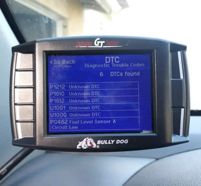
(Image credit: Nissan Frontier Forum)
Let’s learn how these modules collaborate to ensure seamless vehicle operation.
The ABS control module is responsible for ensuring that the wheels do not lock up during braking, allowing the driver to maintain steering control. It constantly monitors the wheel speed sensors and sends signals to the ECM to adjust engine power or apply the brakes as needed to prevent wheel lock-up.
Meanwhile, the ECM serves as the central control unit for the engine. It receives information from various sensors in the vehicle to optimize engine performance, fuel efficiency, and emissions. Additionally, the ECM communicates with other control modules, including the ABS control module, to coordinate their functions and ensure that the vehicle operates smoothly.
Is The P1212 Nissan Code Severe?
The severity of the P1212 Nissan code can be classified as moderate to high. Although it may not require immediate attention, addressing the underlying issue promptly is crucial. This ensures the proper functioning of your ABS system and helps maintain the overall performance of your vehicle.
While you can continue driving with the P1212 code in the short term, it is unsafe, and you should drive with caution. Insufficient communication between the ABS control module and the ECM can result in the ABS system not operating as intended. This can affect your vehicle’s braking performance and lead to ABS system malfunctions and traction control issues. Therefore, to ensure optimal safety and functionality, promptly diagnosing and repairing the issue is strongly recommended.
What Are The Warning Signs of the P1212 Nissan Code?
The warning signs of the P1212 Nissan code may include the following:
- Illuminated ABS, TCS, and/or SLIP warning lights
- Decreased braking performance
- Unusual noises during braking
- Traction control issues
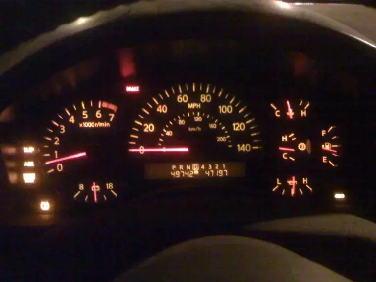
(Image credit: titantalk.com)
Read more: Nissan Dashboard Warning Lights and Meanings (FULL list, FREE Download)
What Causes The P1212 Nissan Code?
The P1212 Nissan code can be caused by the following:
- Corroded harness connector on the ABS unit
- Harness or connectors with open or shorted CAN communication lines
- Faulty ABS actuator and electric unit (control unit)
- Damaged ABS fuse
- Dead or weak battery
How To Diagnose And Fix The P1212 Nissan Code?
Get ready to tackle the P1212 Nissan code like a pro! In this section, we’ll guide you through the process of diagnosing and fixing the issue.
Note: If the retrieved trouble codes include DTC UXXX or P0607, prioritize repairing them before proceeding with the following procedure.
Essential Tools And Parts
- WD-40 Specialist® Contact Cleaner
- Battery terminal cleaner
- Automotive wrenches
- Screwdrivers
- Multimeter
- ABS fuse
- Nissan battery
Step-by-step Procedure
Step 1: Inspect the ABS control module, wiring, and connectors
Thoroughly examine the ABS control module, wiring harness, and connectors for any signs of damage, corrosion, or loose connections. Clean the affected components using an electrical contact cleaner if you find any issues. Repair or replace any damaged parts as necessary.
Pro Tip: Pay attention to the ABS connector, as it’s one of the most common causes. Clean corroded connectors using a suitable electrical contact cleaner. WD-40 Specialist® Contact Cleaner is a good choice.
Step 2: Check the ABS fuse
Locate the ABS fuse in the fuse box. It is typically a red 10-amp fuse located on the passenger side by the overflow tank in the engine bay. Inspect the fuse visually to determine if it is blown or damaged. If you find a blown fuse, replace it with a new fuse of the same amperage rating.
Step 3: Examine the battery
Ensure that the vehicle’s battery has sufficient charge. If needed, recharge the battery. Inspect the battery cable for signs of corrosion or loose connections. Clean the battery cable and terminals using a battery terminal cleaner or a mixture of baking soda and water. If the battery is old or faulty, consider replacing it with a new one.
Step 4: Reset the ABS system and test drive
Disconnect the negative terminal of the battery and wait for at least 10 minutes. Reconnect the negative terminal and start the vehicle. Take the vehicle for a test drive to verify if the P1212 error code has been cleared. During the test drive, ensure that the ABS system functions properly and that no warning lights or error codes appear.
If the error code persists after following these steps, it is recommended to consult a qualified mechanic or Nissan dealership for further diagnosis and assistance.
Estimated Costs For P1212 Code In Nissan Vehicles
The procedure provided above for addressing the P1212 code in Nissan vehicles is suitable for DIY enthusiasts with intermediate automotive repair skills. However, it is essential to note that diagnosing and repairing electrical issues can be complex. If you lack confidence in your abilities or do not have the necessary tools, it is highly advisable to seek assistance from a qualified mechanic or Nissan dealership.
When it comes to the cost of repairing the P1212 code, it can vary depending on several factors, including the specific model of your vehicle, the extent of the issue, and prevailing labor rates in your area. As the code is related to communication issues within the ABS system, the cost may involve various elements, as outlined in the table below:
| Repair Task | Estimated Cost Range |
| Diagnostic Fee | $50 – $150 |
| ABS Fuse Replacement | $5 – $20 |
| Battery Replacement | $100 – $300 |
| Wiring Repair | $100 – $500 |
| Connector Replacement/Repair | $50 – $200 (per connector) |
| ABS Control Module Replacement/Repair | $300 – $800 (excluding programming) |
| Labor Costs (per hour) | $80 – $150 |
P1212 Nissan Infographic
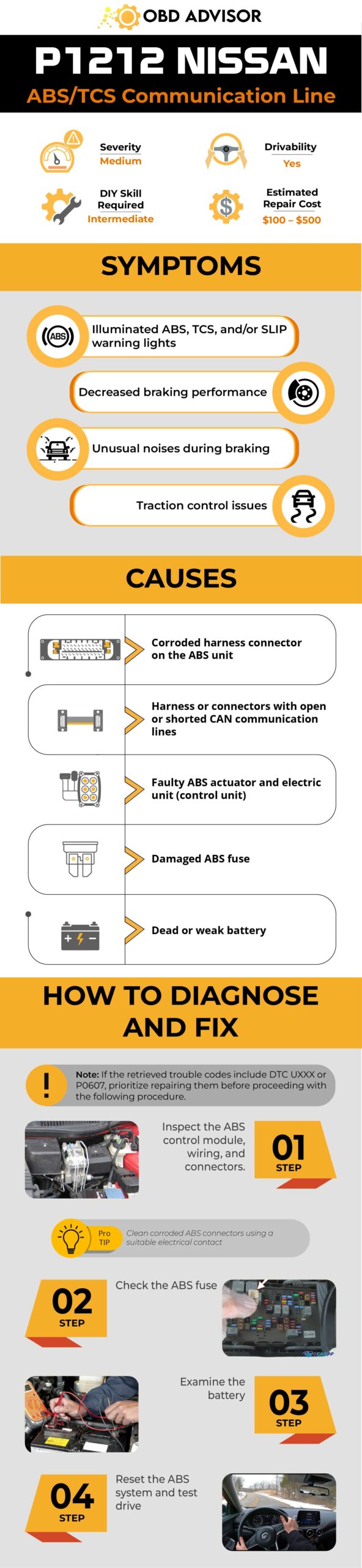
Final Thoughts
In conclusion, tackling the P1212 code in Nissan vehicles requires careful consideration. If you’re a DIY enthusiast with intermediate to advanced automotive repair skills, you can give it a shot. Just remember, electrical issues can be tricky, so don’t hesitate to seek professional help if needed.
The cost of repairs can vary based on factors like your vehicle model and the extent of the issue. It’s crucial to weigh your skills and resources before diving in.
Got more questions or insights? Comment below!
And if you found this information helpful, share it with others who might benefit. Let’s hit the road with confidence and keep those wheels turning!
References Sources
- P1212 TCS communication line, Nissan Rogue Owners & Service Manual Website
- What is an Anti-lock Brake System, Nissan of Mobile
P1610 Nissan – Lock Mode: Causes, Symptoms & Solutions
P1610 Nissan – Lock Mode: Causes, Symptoms & Solutions
Is your Nissan refusing to start, and you find the annoying P1610 code on the scanner? I know how frustrating it can be! That’s why I’m here to help!
Simply put, the P1610 Nissan code suggests potential issues with the NATS system or the use of an incorrect key. Don’t wait any longer; gain valuable insights and learn how to fix it in this article!
P1610 Nissan: An Overview
Let’s take a quick look at the essential details of the P1610 Nissan code!
- Definition: Immobilizer Lock Mode
- Severity: Medium
- DIY Skill Level: Intermediate
- Continue To Drive?: No
- Estimated Repair Cost: $30 – $200
P1610 Nissan Code: Immobilizer Lock Mode Explained
The P1610 code, defined as “Immobilizer Lock Mode,” is specifically associated with the Nissan Anti-Theft System (NATS), also known as the Vehicle Immobilizer System. When this code appears, it signifies that the immobilizer system has entered lock mode, preventing the vehicle from starting even with the correct key. It is commonly triggered in various Nissan and Infiniti models, including the Altima, Almera, Frontier, Murano, Pathfinder, Sentra, and Maxima.
The NATS is designed to prevent the unauthorized starting of the vehicle by immobilizing the engine unless the correct key is detected. It works by immobilizing the engine unless the correct key is detected. When you insert the key into the ignition, the NATS antenna amplifier reads the unique binary code transmitted by the key. If the Engine Control Module (ECM) determines that the coded key is valid and matches the registered keys, it activates the fuel-injection sequence, allowing the engine to start.
However, if the ECM detects an issue with the key or the NATS system during the starting process, it will trigger the P1610 code, indicating a problem with the immobilizer system.
More specifically, this code becomes active when engine start is attempted 5 or more times using an unprogrammed or faulty key. Other associated codes may include P1614, P1612, P1611, and P1615, each indicating specific issues related to the NATS system, such as antenna amplifier malfunction, key problems, or communication failures.
P1610 Nissan – Technical Service Bulletins
Nissan knows that many people experience the P1610 code issue, and they have released Technical Service Bulletins (TSBs) to help. For example, if you own a 2005-2008 Nissan car with the NATS/Immobilizer system, there is a TSB called “MY 2005 – 2008; ENGINE NO-START WITH NATS DTC P1610” that provides guidance on how to diagnose and fix the problem. So, if you come across the P1610 Nissan code or any NATS-related issues, it’s a good idea to check if your vehicle is covered under any TSB.
How Serious is the Nissan P1610 Code?
The P1610 code is classified as a medium-severity issue. It relates to the immobilizer system and may prevent your vehicle from starting. While it doesn’t typically pose an immediate safety concern, it’s important to take it seriously.
(Image credit: obrazki.elektroda.pl)
If you encounter the P1610 code, you won’t be able to continue driving because the car enters lock mode. Trying to escape lock mode without fixing the underlying problem is not recommended.
Address the issue promptly to avoid future inconvenience or starting problems. Ignoring the code could result in occasional difficulty starting your car or complete immobilization.
Symptoms Of The P1610 Nissan Code
When your Nissan is affected by the P1610 code, you may experience the following symptoms:
- Engine cranks but does not start
- Intermittent starting issues
- Security indicator light stays on or flashes
- Malfunction indicator lamp (MIL)/ check engine light illuminates
Important Note: Check the security indicator light. If it remains off during or after engine cranking, the issue may not be related to NATS.
Causes Of The P1610 Nissan Code
The P1610 code can be triggered by various factors and underlying issues, including:
- Faulty NATS ignition key (most possibly the transponder)
- NATS antenna amplifier malfunction
- Issues with the Body Control Module (BCM) or Immobilizer Control Unit (IMMU)
- Problems with the ECM
- Wiring or connection problems within the NATS system
Read more: Nissan OBD1/OBD2 Codes List [Free PDF Download]
P1610 Nissan Code: Diagnosis And Repair Guide
In this section, we’ll walk you through diagnosing and resolving the P1610 error code in your Nissan, providing valuable repair insights along the way.
Essential Tools And Parts
- Test light or multimeter
- NATS ignition key(s)
- Replacement NATS antenna amplifier (if necessary)
- Wiring diagrams and service manuals (for reference)
Step-by-Step Procedure
1. Try alternate keys
If you have a spare programmed key, try using it to escape your vehicle from lock mode.
- Method 1: Insert the spare key into the ignition and turn it to the ON position for 5 seconds, then turn it back to the OFF position. Repeat this process three times.
- Method 2: If the above method doesn’t work, you can try disconnecting the vehicle’s battery for approximately 30 minutes.
After reconnecting the battery, attempt to start the car using the spare key.
2. Inspect and replace/reprogram key
Carefully examine the key for any visible damage, such as cracks, chips, or excessive wear.
- If the key shows signs of damage or wear, repair the faulty components or replace the whole key. Make sure you have the new key properly programmed.
- If the key is in good condition, it may need reprogramming. Consult a locksmith or Nissan dealership for key reprogramming services.
3. Test NATS antenna amplifier
- Locate the NATS antenna amplifier, typically near the ignition switch or the key insertion area.
- With the ignition key in the OFF position, use a test light or multimeter to check for power and ground at the NATS antenna amplifier.
- If there is no power or ground, further investigation may be required, and it is recommended to consult a professional or Nissan dealership for assistance.
4. Check NATS wiring and connections
- Inspect the wiring harness and connections related to the NATS system.
- Pay attention to any visible indications of harm, such as wires that are damaged or showing signs of wear and tear, any corrosion or rust, or connections that are not securely attached.
- Repair or replace any damaged wiring or connections as necessary.
5. Consider BCM and/or IMMU replacement
- If the P1614 code, indicating a BCM or IMMU issue, continues to appear consistently after attempting the previous steps, it may be necessary to replace the BCM and/or the IMMU.
- It is recommended to seek the assistance of a professional technician or visit a Nissan dealership for accurate diagnosis and replacement of the affected components.
Note: Consult the vehicle’s specific service manual or wiring diagrams for detailed instructions and diagrams tailored to your Nissan model.
DIY Repair Level And Estimated Costs
The DIY repair level for addressing the P1610 code can range from moderate to advanced, depending on your experience and comfort level with automotive repairs. While some steps, such as escaping the lock mode, can be performed by most DIY enthusiasts, other tasks may require specialized knowledge and tools.
Below is a table outlining potential repair tasks related to the P1610 issue in a Nissan vehicle:
| Repair Task | Cost Range |
| Diagnostic fee | $50 – $150 |
| Wiring repair | $50 – $200 |
| Key replacement/reprogramming | $50 – $300 |
| NATS antenna amplifier replacement | $100 – $300 |
| BCM – IMMU replacement | $200 – $800 |
It is important to note that estimated costs may vary based on Nissan model, location, and parts availability. Consult a mechanic or Nissan dealership for accurate diagnostics and professional repairs to ensure proper NATS system functioning.
Wrapping Up
Navigating the P1610 Nissan code may seem daunting. Still, armed with the knowledge we’ve shared, you’re well-equipped to tackle this immobilizer-related challenge. Remember, timely diagnosis and repair are vital to ensuring a smooth driving experience.
If you found this article helpful, please share it with fellow Nissan owners who may benefit from it. We also encourage you to leave your comments and questions below.
Stay informed, stay empowered, and keep your Nissan running at its best. Safe travels!
Reference Sources
- Nissan & Infiniti Tech News, An Introduction to Nissan Anti-Theft Systems.
- Nissan Technical Service Bulletin, ENGINE WILL NOT START NVIS/NATS SYSTEM DESCRIPTION KEY REGISTRATION.
P0700 – Transmission control system (MIL request)
P0700 – Transmission control system (MIL request)
The P0700 OBD2 code is a relatively generic code—and one that you should take seriously. It indicates a malfunction in the transmission control system, preventing your car from changing gears properly, making you a hazard to yourself and others on the road.
Fixes for the P0700 code may be specific to your vehicle’s make and model. Take this into account as you’re going through your diagnosis. Follow any advice outlined in your manual over the general diagnosis steps laid out below.
The P0700 code solutions range from simply replacing your transmission fluid to an entire overhaul of your transmission system. The good news is, an OBD2 scan tool gives you all the data you need to diagnose this trouble code.
P0700 code definition
Transmission control system TCS malfunction
What does P0700 mean?
The P0700 OBD2 code triggers when a malfunction is detected in your transmission controls. Most modern cars have a specific control module for the automatic transition system called the transmission control module, or TCM.
The TCM’s role in your system is to monitor the transmission system’s sensors and send that data to the engine control module (ECM). If any issues are detected when the ECM reads this data, the P0700 trouble code is activated. Along with the check engine light, activation of this code triggers a failsafe mode. Your system will remain in this mode until the fault has been repaired and regular operation can resume.
The P0700 OBD2 code only tells you there’s some problem in your transmission system. You’ll need to dig a bit deeper to find the problem’s exact source, which makes your OBD2 scan tool your best friend when you need to fix a P0700 code.
What are the symptoms of the P0700 code?
You will likely notice drivability issues with code P0700, mainly caused by slips in the transmission. The most common symptoms include:
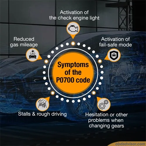
- Activation of the check engine light,
- Activation of fail-safe mode,
- Hesitation or other problems when changing gears,
- Stalls and rough driving,
- Reduced gas mileage.
What are the causes of P0700?
- Shift solenoid is defective,
- The engine coolant sensor is defective,
- Short or open circuit in TCM,
- Faults in the transmission valve body,
- TCM is faulty,
- PCM is faulty (rare).
How serious is the P0700 code?
The P0700 is very serious. Issues with your transmission control system can prevent your car from changing gears, potentially making your car dangerous to drive. You should stop immediately driving when P0700 activates and avoid driving (aside from controlled diagnostic road tests) until you’ve repaired the problem.
How to diagnose the P0700 code?
While P0700 is a generic powertrain code, the specific fix can vary depending on your vehicle. Check your car’s manual and search for technical service bulletins applicable to your make and model before starting your diagnosis.
Tools you’ll need: OBD2 scan tool.
Here are the steps:
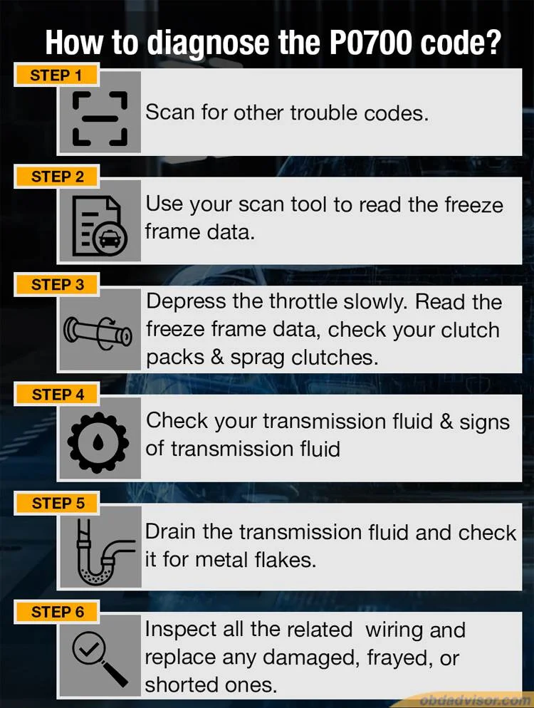
- Scan for other trouble codes. Most of the time, P0700 is activated, but it isn’t the only trouble code. You will commonly see codes related to the shift solenoid. Diagnose these codes first. Since they’re more specific, it’s often easier to locate the issue.
- Use your scan tool to read the freeze frame data. Pay particular attention to the RPM, throttle position, and engine torque readings. Compare the RPM’s input speed and output speed.
- Depress the throttle slowly, starting above 45mph. Read the freeze frame data as you do this. The Slip Speed should never go over 50rpm. If it increases, the converter clutch is slipping. Alternatively, if the Slip Speed is steady, but the output shaft speed decreases, the transmission is slipping internally. Check your clutch packs and sprag clutches for wear.
- Check your transmission fluid. It should be read and clear of debris, and the reservoir should be filled sufficiently. Also, check for signs of transmission fluid on your engine components or pooled fluid beneath your car, which could indicate a leak.
- Drain the transmission fluid and check it for metal flakes. These are from mechanical wear in the transmission and are often seen when the transmission is failing. If these flakes are present, they may have clogged the solenoid, causing it to fail. Metal flakes may also indicate your transmission needs to be rebuilt or replaced.
- Inspect all the wiring related to the transmission system. Replace any wires that are damaged, frayed, or shorted.
Common mistakes to avoid while diagnosing the P0700 code
The biggest mistake is to diagnose based on your car’s symptoms rather than reading the trouble codes. The drivability issues associated with P0700 can be misinterpreted as engine misfires. With a serious code like this, it’s crucial to conduct a thorough diagnosis using an OBD2 scan tool and ensure you’ve fixed the issue.
What should you do to fix the code P0700?
- Replace any faulty or damaged wires found during your diagnosis. Ensure all connections are secure.
- Locate the source of any transmission fluid leaks and replace the faulty component.
- Drain your transmission fluid, then remove and replace the filter. Examine both the fluid and filter for debris. If any is present, flush your system and put in fresh transmission fluid. If there are many metal flakes in your transmission fluid, take your car to a transmission expert. There is a more serious issue in your system that needs to be addressed.
- Replace the transmission shift solenoid if it is dirty or damaged.
- Clear all OBD2 codes and take a test drive, replicating the conditions of the initial failure. If the P0700 code comes back, you may have more complicated electrical problems. Take your car to a mechanic for further diagnosis.
Tips to avoid P0700 in the future
Proper maintenance of your transmission system is the best way to avoid the P0700 code. Check your transmission fluid regularly and replace it when it gets dirty. If you see drips or puddles of transmission fluid in your garage or driveway, locate and fix the leak right away, even if no trouble codes are active.
Read more: P0440: Meaning, Symptoms, Causes, Diagnostics, and Fixes.
P0303 – Cylinder 3 misfire detected
P0303 – Cylinder 3 misfire detected
The P0303 code activates whenever cylinder 3 in your engine misfires. While a single misfire may not be cause for concern, repeated misfires are a sign of a bigger problem and could lead to long-term damage.
Finding the source of the misfire isn’t always easy, even when you know which cylinder it’s affecting. If other trouble codes are active, those can be a big help in isolating the issue. If not, there are steps you can follow to correctly diagnose the P0303 OBD2 code.
Diagnosing P0303 can be a time-consuming process. The good news is, it doesn’t always mean an expensive or difficult repair. Read on below to learn more.
P0303 code definition
P0303 code definition (generic): Cylinder #3 misfire detected
P0303 Ford code definition: Cylinder 3 misfire detected
P0303 Nissan code definition: Number 3 cylinder misfire detected
P0303 Subaru code definition: Cylinder 3 misfire detected
P0303 Toyota code definition: Cylinder 3 misfire detected
P0303 VW code definition: Cylinder 3 misfire detected
What does P0303 mean?
The generic powertrain code P0303 tells you there’s been a misfire in cylinder 3. You’ll usually see it along with the broader P0300 OBD2 code, which activates for a random misfire. Other trouble codes might come up, as well, including those relating to the air/fuel mixture.
While this code is generic, the fixes can vary depending on your car’s make and model. Always check your vehicle’s manual for recommended repairs before starting your diagnosis. Check for any technical service bulletins, as well, in case there’s a known issue for your car.
The exact placement of the cylinders in your engine depends on its size and style. In most V8 engines, cylinder 3 is directly behind cylinder 1, on the right side when you’re facing the engine. There are major manufacturers, however—most notably Ford—that number the cylinders from front to back, making cylinder #3 the third one back on the right side. Verify how your cylinders are numbered in your manual before starting your diagnosis.
What are the symptoms of the P0303 code?
If the misfire was a one-off problem, you may not experience any drivability symptoms. In most cases, though, they will be severe. The most common include:
- Activation of the check engine light
- Shaking or rough running from the engine
- The smell of fuel in the exhaust
- Jerking and hesitation when accelerating
- Reduced engine power
- Reduced gas mileage
- Hard starts and stalls

What are the causes of P0303?
The most common causes of the P0303 OBD2 code are:
- Worn or faulty spark plugs
- Worn or faulty wiring around the spark plugs
- Worn or faulty coil packs
- Faulty distributor
- Faulty fuel injector
Cylinder 3 misfires can also be caused by:
- Vacuum leaks in the fuel or exhaust systems
- Faulty camshaft sensor, crankshaft sensor, or oxygen sensor
- Faulty or clogged catalytic converter
- Low fuel pressure
- Low engine compression
- Fuel quality incorrect for the engine
- Faulty computer (rare)
How serious is the P0303 code?
The P0303 trouble code is potentially quite serious. Misfires in the engine can cause damage to internal systems. The erratic driving that’s often a symptom of this trouble code also makes the vehicle unsafe to drive. Avoid driving your vehicle until you’ve repaired the issue.
How to diagnose the P0303 code
Tools you’ll need:
- OBD2 scan tool
- Basic tool kit (a screwdriver, a ratchet set, a socket set, etc.)
- Digital multimeter
- Fuel pressure gauge
- Compression tester
Method:
- Use the OBD2 scan tool to check for other trouble codes. If any others come up, fix those first.
- Clear all codes and test drive your vehicle. If P0303 doesn’t come back and you’re experiencing no symptoms, it may have been a random misfire.
- Inspect all the vacuum hoses in your system for air leaks. Be sure to feel any spots you can’t see for hidden damage or holes.
- Inspect the ignition coils and wiring for damage and ensure the connections are secure. Check the spark plug wires for the same issues.
- If your engine has movable coil packs, swap the cylinder 3 coil pack with the one in cylinder 1. Clear the codes and rescan your vehicle. If the misfire moves, the coil pack is likely faulty.
- Visually inspect the spark plugs. If they’re coated in oil, corroded, or fouled by carbon build-up, clean or replace them.
- Use a digital multimeter to test the spark plug wires. Remove each wire and connect one multimeter lead to each end. Compare the reading with your vehicle’s specifications.
- Check the fuel injectors using a digital multimeter. Inspect the wiring for damage or loose connections.
- Use a fuel pressure gauge to check your fuel pressure. If it’s too low, either the fuel pressure regulator or the fuel pump is failing.
- Perform a compression test to check for mechanical causes of the misfire, like a burned valve or worn valve guide. This test will also tell you if the engine timing is off due to a skipped or misaligned timing chain.
Common mistakes to avoid while diagnosing the P0303 code
Many people start replacing big components before they check the little things like leaking hoses or damaged wires. Be thorough in your diagnosis so you don’t overlook potentially cheap and easy solutions.
What should you do to fix the code P0303?
- Replace any damaged wires found during your diagnosis. If you located more than 2 bad wires around the spark plugs, it’s recommended to replace the entire set.
- Repair or replace any leaking hoses or other sources of air leaks in the air intake system.
- If the coil pack failed or the spark plugs were fouled, replace them.
- Replace any fuel injectors that failed step 8 of the diagnosis. If your fuel pressure is still too low, replace your fuel pump.
Tips to avoid P0303 in the future
Problems with the air-to-fuel ratio often lead to misfires. Leaks in the vacuum system make the mix too lean. Inspect your vacuum hoses periodically for leaks and ensure they’re fastened securely, away from any engine components that could cause damage.
Read more:
P1399 Honda – Random Cylinder Misfire Detected
P0300 Code: Meaning, Symptoms, Causes, and Fixes
P1604 Toyota Code: Startability Issues And Fixes
P1604 Toyota Code: Startability Issues And Fixes
Get ready to tackle the P1604 Toyota code with our informative guide. If you’re experiencing engine starting problems, this article is your roadmap to resolution. I’ll walk you through the possible causes, step-by-step diagnosis, and effective solutions for the P1604 code.
Say goodbye to the frustration and hello to a smoothly running vehicle. Let’s dive in and address the P1604 Toyota code together.
P1604 Toyota: A Quick Overview
Here’s a summary of the P1604 for Toyota. Give it a check now!
- Definition: Startability Malfunction
- Severity: Medium
- DIY Skill Level: Intermediate
- Continue To Drive?: No
- Estimated Repair Cost: $50 – $500
What Does The P1604 Mean In Toyota Vehicles?
The P1604 diagnostic trouble code (DTC) in Toyota vehicles is defined as “Startability Malfunction” and refers to engine starting trouble or long cranking times. This code is stored when the engine fails to start despite receiving the STA (Start) signal or when it takes an extended period for the engine to start. In addition, the code can be triggered if the engine speed is low or if the engine stalls shortly after starting.
Specifically, the P1604 Toyota code can be triggered if either of the following conditions is met:
- 1. The engine speed remains below 500 RPM for a specific duration while the STA signal is active.
or
- 2. The engine speed rapidly drops to 200 RPM or lower within approximately 2 seconds after the engine starts, following an initial speed of 500 RPM or higher.

(Credit: tacomaworld.com)
The P1604 code commonly occurs in various Toyota models. Some of the models that may experience this code include the Toyota Camry, Corolla, RAV4, Tundra, Camry, and Tacoma.
In some cases, the P1604 DTC may be stored due to engine starting difficulties caused by a fuel shortage. Therefore, checking the fuel level is an important initial step to ensure accurate diagnosis and avoid unnecessary troubleshooting efforts.
Read more: P1605 Toyota Code: Engine Rough Idling Solutions
How Serious Is The P1604 Toyota Code?
The severity level of the P1604 Toyota DTC is considered moderate. While this code indicates engine starting trouble or prolonged cranking times, it does not pose an immediate safety risk or cause significant damage to the vehicle. However, it is not advisable to continue driving with this code present.
When the P1604 DTC is active, the engine may experience difficulties starting, low engine speed, or stalling after starting. This can lead to inconvenience and potential breakdowns, especially in situations where the engine fails to start altogether. To avoid unexpected issues and ensure reliable vehicle operation, it is recommended to address the underlying problem causing the P1604 code immediately.
What Are The Signs Of The P1604 Toyota Code?
The following are common symptoms associated with the P1604 Toyota DTC:
- Check engine light (MIL) illuminated
- Engine fails to start
- Extended cranking time
- Low engine speed
- Engine stalls shortly after starting
- Engine misfire
What Are The Causes Of The P1604 Code In Toyota Vehicles?
The P1604 Toyota DTC can be caused by various factors, including:
- Immobilizer system malfunction
- Engine assembly issues such as excess friction or compression loss
- Faulty starter assembly
- Malfunctioning crankshaft position sensor and/or camshaft position sensor
- Malfunctioning engine coolant temperature sensor
- Issues with fuel system (fuel pump, fuel injector, etc.)
- Issues with the throttle body or pressure regulator
- Battery-related problems
- Faulty drive plate or flywheel
- Malfunctioning spark plug or ignition coil circuit
- Problems with the intake system or camshaft timing oil control valve
- Malfunctioning mass air flow meter or air-fuel ratio sensor
- Valve timing issues
- Issues with the purge VSV (Vacuum Switching Valve)
- Malfunctioning intake valve
- Problems with the Engine Control Module (ECM)
Please note that further diagnostics may be necessary to pinpoint the exact cause of the P1604 Toyota code.
Read more: Toyota OBD1/OBD2 Codes List [FREE DOWNLOAD]
How To Diagnose And Repair P1604 Toyota Code?
In this section, I’ll talk about the tools and parts you might need, walk you through a guide for diagnosing and resolving the P1604 Toyota code issue, and discuss the level of DIY repair required, along with potential cost estimates.
Though some tasks can be tackled by DIY enthusiasts, it is advisable to seek professional assistance if unsure or when dealing with more complex repairs.
Diagnostic Tools And Essential Parts
To diagnose and repair the P1604 Toyota code, you may need the following tools and parts:
- OBD-II scan tool
- Multimeter
- Fuel pressure gauge
- Spark plug wrench
- Socket set
- Replacement parts (based on diagnosis)
Step-by-Step Guide
- Use an OBD-II scan tool to retrieve and record any additional trouble codes and freeze frame data.
- Inspect the battery and electrical connections for any signs of corrosion or damage. Repair any detected problem.
- Check the fuel level and ensure the vehicle has an adequate fuel supply. Fill the tank if the fuel level is low.
- Test the fuel pressure using a fuel pressure gauge to ensure it meets manufacturer specifications. Make any modifications if needed.
- Inspect the spark plugs for wear, fouling, or damage and replace if necessary.
- Use a multimeter to test the crankshaft position sensor and camshaft position sensor for proper operation. Repair or replace the parts if problems occur.
- Check the engine coolant temperature sensor for any faults or inconsistencies.
- Inspect the wiring and connections related to the starting system and repair any damaged or loose connections.
- Perform a thorough inspection of the intake system, including the throttle body and intake valve, for any obstructions or malfunctioning components. Repair or replace if necessary.
Note:
- This guide may not address all possible causes, and if the code reappears or persists, we highly recommend seeking the assistance of a skilled mechanic.
- It is important to record the freeze frame data. This data is helpful in determining the underlying cause of the code. Consult this TSB for more details.
DIY Repair Level And Estimated Costs
The diagnostic procedure for the P1604 Toyota code requires intermediate-level automotive repair knowledge and experience.
While DIY enthusiasts can perform some steps, such as checking electrical connections and inspecting spark plugs, other tasks may necessitate specialized tools or expertise. We recommend consulting a professional mechanic for a comprehensive diagnosis and repair.
The estimated costs for repairing the P1604 code can vary depending on the specific cause and the necessary repairs. Here is a general cost breakdown:
| Repair Task | Estimated Cost |
| Replacement of spark plugs | $40 – $100 |
| Repairing wiring/connectors | $50 – $200 |
| Replacement of sensors | $100 – $300 |
| Fuel system repairs | $100 – $500 |
| Other component repairs | Varies |
Conclusion
Resolving the P1604 Toyota code and getting your vehicle back on track is within your reach. Furthermore, with the knowledge and steps provided, you can confidently diagnose and address this issue. Don’t keep this valuable information to yourself – share it with fellow Toyota owners who may be encountering the same challenge.
Remember, if the P1604 code reappears or persists, it’s advisable to seek the expertise of a skilled mechanic for an accurate diagnosis and precise repairs.
If you have any questions or success stories, we’re here to listen. Share your experiences and insights in the comments section below. Let’s engage in a discussion and support each other!
Reference Sources
- JustAnswer, P1604 Startability Malfunction
- RepairSmith, 10 Prominent Weak Car Battery Symptoms
Toyota OBD1/OBD2 Codes List [FREE DOWNLOAD]
Toyota OBD1/OBD2 Codes List [FREE DOWNLOAD]
Buckle up and get ready for a thrilling ride through the world of Toyota fault codes with our complete list of OBD1 and OBD2 codes. Designed to provide valuable insights into the diagnostic codes of your Toyota vehicle, this guide is suitable for both classic Toyota 90s cars and newer models.
With this guide, you can quickly identify and diagnose any potential issues, ensuring optimal performance and longevity for your Toyota.
So, let’s dive in!
Toyota OBD1 Codes List And Definition [FULL]
Free download: Full Toyota OBD1 Trouble Codes List and Meaning PDF
Note: Use the search box in the table below to quickly find the specific code you’re looking for.
| Code | Definition |
|---|---|
| Code 1 | Normal Condition |
| Code 2 | Air Flow Meter signal |
| Code 3 | Ignition signal |
| Code 4 | Engine Coolant Temperature Sensor signal |
| Code 5 | Oxygen Sensor |
| Code 6 | RPM signal (Crank Angle Pulse) |
| Code 7 | Throttle Position Sensor signal |
| Code 8 | Intake Air Temperature Sensor signal |
| Code 9 | Vehicle Speed Sensor signal |
| Code 10 | Starter signal |
| Code 11 | Switch signal |
| Code 11 | ECU/ECM |
| Code 12 | Knock Control Sensor signal |
| Code 12 | RPM signal |
| Code 13 | Knock Control CPU (ECM) |
| Code 13 | RPM signal |
| Code 14 | Turbocharger Pressure |
| Code 14 | Ignition signal |
| Code 21 | Oxygen Sensor |
| Code 22 | Engine Coolant Temperature Sensor signal |
| Code 23 | Intake Air Temperature Sensor signal |
| Code 24 | Intake Air Temperature Sensor signal |
| Code 25 | Air-Fuel Ratio Lean |
| Code 26 | Air-Fuel Ratio Rich |
| Code 27 | Sub Oxygen Sensor signal |
| Code 28 | No 2 Oxygen Sensor signal |
| Code 31 | Air Flow Meter signal (Vacuum Sensor signal) |
| Code 32 | Air Flow Meter signal |
| Code 34 | Turbocharger Pressure signal |
| Code 35 | Turbocharger Pressure Sensor signal |
| Code 35 | HAC Sensor signal |
| Code 41 | Throttle Position Sensor signal |
| Code 42 | Vehicle Speed Sensor signal |
| Code 43 | Starter signal |
| Code 51 | Switch signal |
| Code 52 | Knock Sensor signal |
| Code 53 | Knock Sensor signal |
| Code 54 | Inter-cooler ECM signal |
| Code 71 | EGR System |
| Code 72 | Fuel Cut Solenoid signal |
| Code 78 | Fuel Pump Control signal |
| Code 81 | TCM Communication |
| Code 83 | TCM Communication |
| Code 84 | TCM Communication |
| Code 85 | TCM Communication |
Toyota OBD2 Codes List And Definition [Free Download]
Free download: Full Toyota OBD2 Trouble Codes List and Meaning PDF
Our user-friendly code list is divided into four parts: Powertrain, Network, Body, and Chassis, which helps you quickly find the codes you need for engine, network, body control, and chassis issues.
Note: Use the search box in the table below to quickly find the specific code you’re looking for.
Powertrain (P) Codes List
| Code | Definition |
|---|---|
| P0100 | Mass Or Volume Air Flow Circuit Malfunction |
| P0101 | Mass Or Volume Air Flow Circuit Range/Performance Problem |
| P0102 | Mass Or Volume Air Flow Circuit Low Input |
| P0103 | Mass Or Volume Air Flow Circuit High Input |
| P0104 | Mass Or Volume Air Flow Circuit Intermittent |
| P0105 | Manifold Absolute Pressure/Barometric Pressure Circuit Malfunction |
| P0106 | Manifold Absolute Pressure/Barometric Pressure Circuit Range/Performance Problem |
| P0107 | Manifold Absolute Pressure/Barometric Pressure Circuit Low Input |
| P0108 | Manifold Absolute Pressure/Barometric Pressure Circuit High Input |
| P0109 | Manifold Absolute Pressure/Barometric Pressure Circuit Intermittent |
| P0110 | Intake Air Temperature Circuit Malfunction |
| P0111 | Intake Air Temperature Circuit Range/Performance Problem |
| P0112 | Intake Air Temperature Circuit Low Input |
| P0113 | Intake Air Temperature Circuit High Input |
| P0114 | Intake Air Temperature Circuit Intermittent |
| P0115 | Engine Coolant Temperature Circuit Malfunction |
| P0116 | Engine Coolant Temperature Circuit Range/Performance Problem |
| P0117 | Engine Coolant Temperature Circuit Low Input |
| P0118 | Engine Coolant Temperature Circuit High Input |
| P0119 | Engine Coolant Temperature Circuit Intermittent |
| P0120 | Throttle/Pedal Position Sensor/Switch “A” Circuit Malfunction |
| P0121 | Throttle/Pedal Position Sensor/Switch “A” Circuit Range/Performance Problem |
| P0122 | Throttle/Pedal Position Sensor/Switch “A” Circuit Low Input |
| P0123 | Throttle/Pedal Position Sensor/Switch “A” Circuit High Input |
| P0124 | Throttle/Pedal Position Sensor/Switch “A” Circuit Intermittent |
| P0125 | Insufficient Coolant Temperature For Closed Loop Fuel Control |
| P0126 | Insufficient Coolant Temperature For Stable Operation |
| P0130 | O2circuit Malfunction (Bank #1 Sensor #1) |
| P0131 | O2sensor Circuit Low Voltage (Bank #1 Sensor #1) |
| P0132 | O2sensor Circuit High Voltage (Bank #1 Sensor #1) |
| P0133 | O2sensor Circuit Slow Response (Bank #1 Sensor #1) |
| P0134 | O2sensor Circuit No Activity Detected (Bank #1 Sensor #1) |
| P0135 | O2sensor Heater Circuit Malfunction (Bank #1 Sensor #1) |
| P0136 | O2sensor Circuit Malfunction (Bank #1 Sensor #2) |
| P0137 | O2sensor Circuit Low Voltage (Bank #1 Sensor #2) |
| P0138 | O2sensor Circuit High Voltage (Bank #1 Sensor #2) |
| P0139 | O2sensor Circuit Slow Response (Bank #1 Sensor #2) |
| P0140 | O2sensor Circuit No Activity Detected (Bank #1 Sensor #2) |
| P0141 | O2sensor Heater Circuit Malfunction (Bank #1 Sensor #2) |
| P0142 | O2sensor Circuit Malfunction (Bank #1 Sensor #3) |
| P0143 | O2sensor Circuit Low Voltage (Bank #1 Sensor #3) |
| P0144 | O2sensor Circuit High Voltage (Bank #1 Sensor #3) |
| P0145 | O2sensor Circuit Slow Response (Bank #1 Sensor #3) |
| P0146 | O2sensor Circuit No Activity Detected (Bank #1 Sensor #3) |
| P0147 | O2sensor Heater Circuit Malfunction (Bank #1 Sensor #3) |
| P0150 | O2sensor Circuit Malfunction (Bank #2 Sensor #1) |
| P0151 | O2sensor Circuit Low Voltage (Bank #2 Sensor #1) |
| P0152 | O2sensor Circuit High Voltage (Bank #2 Sensor #1) |
| P0153 | O2sensor Circuit Slow Response (Bank #2 Sensor #1) |
| P0154 | O2sensor Circuit No Activity Detected (Bank #2 Sensor #1) |
| P0155 | O2sensor Heater Circuit Malfunction (Bank #2 Sensor #1) |
| P0156 | O2sensor Circuit Malfunction (Bank #2 Sensor #2) |
| P0157 | O2sensor Circuit Low Voltage (Bank #2 Sensor #2) |
| P0158 | O2sensor Circuit High Voltage (Bank #2 Sensor #2) |
| P0159 | O2sensor Circuit Slow Response (Bank #2 Sensor #2) |
| P0160 | O2sensor Circuit No Activity Detected (Bank #2 Sensor #2) |
| P0161 | O2sensor Heater Circuit Malfunction (Bank #2 Sensor #2) |
| P0162 | O2sensor Circuit Malfunction (Bank #2 Sensor #3) |
| P0163 | O2sensor Circuit Low Voltage (Bank #2 Sensor #3) |
| P0164 | O2sensor Circuit High Voltage (Bank #2 Sensor #3) |
| P0165 | O2sensor Circuit Slow Response (Bank #2 Sensor #3) |
| P0166 | O2sensor Circuit No Activity Detected (Bank #2 Sensor #3) |
| P0167 | O2sensor Heater Circuit Malfunction (Bank #2 Sensor #3) |
| P0170 | Fuel Trim Malfunction (Bank #1) |
| P0171 | System Too Lean (Bank #1) |
| P0172 | System Too Rich (Bank #1) |
| P0173 | Fuel Trim Malfunction (Bank #2) |
| P0174 | System Too Lean (Bank #2) |
| P0175 | System Too Rich (Bank #2) |
| P0176 | Fuel Composition Sensor Circuit Malfunction |
| P0177 | Fuel Composition Sensor Circuit Range/Performance |
| P0178 | Fuel Composition Sensor Circuit Low Input |
| P0179 | Fuel Composition Sensor Circuit High Input |
| P0180 | Fuel Temperature Sensor “A” Circuit Malfunction |
| P0181 | Fuel Temperature Sensor “A” Circuit Range/Performance |
| P0182 | Fuel Temperature Sensor “A” Circuit Low Input |
| P0183 | Fuel Temperature Sensor “A” Circuit High Input |
| P0184 | Fuel Temperature Sensor “A” Circuit Intermittent |
| P0185 | Fuel Temperature Sensor “B” Circuit Malfunction |
| P0186 | Fuel Temperature Sensor “B” Circuit Range/Performance |
| P0187 | Fuel Temperature Sensor “B” Circuit Low Input |
| P0188 | Fuel Temperature Sensor “B” Circuit High Input |
| P0189 | Fuel Temperature Sensor “B” Circuit Intermittent |
| P0190 | Fuel Rail Pressure Sensor Circuit Malfunction |
| P0191 | Fuel Rail Pressure Sensor Circuit Range/Performance |
| P0192 | Fuel Rail Pressure Sensor Circuit Low Input |
| P0193 | Fuel Rail Pressure Sensor Circuit High Input |
| P0194 | Fuel Rail Pressure Sensor Circuit Intermittent |
| P0195 | Engine Oil Temperature Sensor Malfunction |
| P0196 | Engine Oil Temperature Sensor Range/Performance |
| P0197 | Engine Oil Temperature Sensor Low |
| P0198 | Engine Oil Temperature Sensor High |
| P0199 | Engine Oil Temperature Sensor Intermittent |
| P0200 | Injector Circuit Malfunction |
| P0201 | Injector Circuit Malfunction — Cylinder #1 |
| P0202 | Injector Circuit Malfunction — Cylinder #2 |
| P0203 | Injector Circuit Malfunction — Cylinder #3 |
| P0204 | Injector Circuit Malfunction — Cylinder #4 |
| P0205 | Injector Circuit Malfunction — Cylinder #5 |
| P0206 | Injector Circuit Malfunction — Cylinder #6 |
| P0207 | Injector Circuit Malfunction — Cylinder #7 |
| P0208 | Injector Circuit Malfunction — Cylinder #8 |
| P0209 | Injector Circuit Malfunction — Cylinder #9 |
| P0210 | Injector Circuit Malfunction — Cylinder #10 |
| P0211 | Injector Circuit Malfunction — Cylinder #11 |
| P0212 | Injector Circuit Malfunction — Cylinder #12 |
| P0213 | Cold Start Injector #1 Malfunction |
| P0214 | Cold Start Injector #2 Malfunction |
| P0215 | Engine Shutoff Solenoid Malfunction |
| P0216 | Injection Timing Control Circuit Malfunction |
| P0217 | Engine Over Temperature Condition |
| P0218 | Transmission Over Temperature Condition |
| P0219 | Engine Over Speed Condition |
| P0220 | Throttle/Pedal Position Sensor/Switch “B” Circuit Malfunction |
| P0221 | Throttle/Pedal Position Sensor/Switch “B” Circuit Range/Performance Problem |
| P0222 | Throttle/Pedal Position Sensor/Switch “B” Circuit Low Input |
| P0223 | Throttle/Pedal Position Sensor/Switch “B” Circuit High Input |
| P0224 | Throttle/Pedal Position Sensor/Switch “B” Circuit Intermittent |
| P0225 | Throttle/Pedal Position Sensor/Switch “C” Circuit Malfunction |
| P0226 | Throttle/Pedal Position Sensor/Switch “C” Circuit Range/Performance Problem |
| P0227 | Throttle/Pedal Position Sensor/Switch “C” Circuit Low Input |
| P0228 | Throttle/Pedal Position Sensor/Switch “C” Circuit High Input |
| P0229 | Throttle/Pedal Position Sensor/Switch “C” Circuit Intermittent |
| P0230 | Fuel Pump Primary Circuit Malfunction |
| P0231 | Fuel Pump Secondary Circuit Low |
| P0232 | Fuel Pump Secondary Circuit High |
| P0233 | Fuel Pump Secondary Circuit Intermittent |
| P0234 | Engine Over Boost Condition |
| P0261 | Cylinder #1 Injector Circuit Low |
| P0262 | Cylinder #1 Injector Circuit High |
| P0263 | Cylinder #1 Contribution/Balance Fault |
| P0264 | Cylinder #2 Injector Circuit Low |
| P0265 | Cylinder #2 Injector Circuit High |
| P0266 | Cylinder #2 Contribution/Balance Fault |
| P0267 | Cylinder #3 Injector Circuit Low |
| P0268 | Cylinder #3 Injector Circuit High |
| P0269 | Cylinder #3 Contribution/Balance Fault |
| P0270 | Cylinder #4 Injector Circuit Low |
| P0271 | Cylinder #4 Injector Circuit High |
| P0272 | Cylinder #4 Contribution/Balance Fault |
| P0273 | Cylinder #5 Injector Circuit Low |
| P0274 | Cylinder #5 Injector Circuit High |
| P0275 | Cylinder #5 Contribution/Balance Fault |
| P0276 | Cylinder #6 Injector Circuit Low |
| P0277 | Cylinder #6 Injector Circuit High |
| P0278 | Cylinder #6 Contribution/Balance Fault |
| P0279 | Cylinder #7 Injector Circuit Low |
| P0280 | Cylinder #7 Injector Circuit High |
| P0281 | Cylinder #7 Contribution/Balance Fault |
| P0282 | Cylinder #8 Injector Circuit Low |
| P0283 | Cylinder #8 Injector Circuit High |
| P0284 | Cylinder #8 Contribution/Balance Fault |
| P0285 | Cylinder #9 Injector Circuit Low |
| P0286 | Cylinder #9 Injector Circuit High |
| P0287 | Cylinder #9 Contribution/Balance Fault |
| P0288 | Cylinder #10 Injector Circuit Low |
| P0289 | Cylinder #10 Injector Circuit High |
| P0290 | Cylinder #10 Contribution/Balance Fault |
| P0291 | Cylinder #11 Injector Circuit Low |
| P0292 | Cylinder #11 Injector Circuit High |
| P0293 | Cylinder #11 Contribution/Balance Fault |
| P0294 | Cylinder #12 Injector Circuit Low |
| P0295 | Cylinder #12 Injector Circuit High |
| P0296 | Cylinder #12 Contribution/Balance Fault |
| P0300 | Random/Multiple Cylinder Misfire Detected |
| P0301 | Cylinder #1 — Misfire Detected |
| P0302 | Cylinder #2 — Misfire Detected |
| P0303 | Cylinder #3 — Misfire Detected |
| P0304 | Cylinder #4 — Misfire Detected |
| P0305 | Cylinder #5 — Misfire Detected |
| P0306 | Cylinder #6 — Misfire Detected |
| P0307 | Cylinder #7 — Misfire Detected |
| P0308 | Cylinder #8 — Misfire Detected |
| P0320 | Ignition/Distributor Engine Speed Input Circuit Malfunction |
| P0321 | Ignition/Distributor Engine Speed Input Circuit Range/Performance |
| P0322 | Ignition/Distributor Engine Speed Input Circuit No Signal |
| P0323 | Ignition/Distributor Engine Speed Input Circuit Intermittent |
| P0325 | Knock Sensor #1 — Circuit Malfunction (Bank #1 Or Single Sensor) |
| P0326 | Nock Sensor #1 — Circuit Range/Performance (Bank #1 Or Single Sensor) |
| P0327 | Knock Sensor #1 — Circuit Low Input (Bank #1 Or Single Sensor) |
| P0328 | Knock Sensor #1 — Circuit High Input (Bank #1 Or Single Sensor) |
| P0329 | Knock Sensor #1 — Circuit Input Intermittent (Bank #1 Or Single Sensor) |
| P0330 | Knock Sensor #2 — Circuit Malfunction (Bank #2) |
| P0331 | Knock Sensor #2 — Circuit Range/Performance (Bank #2) |
| P0332 | Knock Sensor #2 — Circuit Low Input (Bank #2) |
| P0333 | Knock Sensor #2 — Circuit High Input (Bank #2) |
| P0334 | Knock Sensor #2 — Circuit Input Intermittent (Bank #2) |
| P0335 | Crankshaft Position Sensor “A” Circuit Malfunction |
| P0336 | Crankshaft Position Sensor “A” Circuit Range/Performance |
| P0337 | Crankshaft Position Sensor “A” Circuit Low Input |
| P0338 | Crankshaft Position Sensor “A” Circuit High Input |
| P0339 | Crankshaft Position Sensor “A” Circuit Intermittent |
| P0340 | Camshaft Position Sensor Circuit Malfunction |
| P0341 | Camshaft Position Sensor Circuit Range/Performance |
| P0342 | Camshaft Position Sensor Circuit Low Input |
| P0343 | Camshaft Position Sensor Circuit High Input |
| P0344 | Camshaft Position Sensor Circuit Intermittent |
| P0350 | Ignition Coil Primary/Secondary Circuit Malfunction |
| P0351 | Ignition Coil “A” Primary/Secondary Circuit Malfunction |
| P0352 | Ignition Coil “B” Primary/Secondary Circuit Malfunction |
| P0353 | Ignition Coil “C” Primary/Secondary Circuit Malfunction |
| P0354 | Ignition Coil “D” Primary/Secondary Circuit Malfunction |
| P0355 | Ignition Coil “E” Primary/Secondary Circuit Malfunction |
| P0356 | Ignition Coil “F” Primary/Secondary Circuit Malfunction |
| P0357 | Ignition Coil “G” Primary/Secondary Circuit Malfunction |
| P0358 | Ignition Coil “H” Primary/Secondary Circuit Malfunction |
| P0359 | Ignition Coil “I” Primary/Secondary Circuit Malfunction |
| P0360 | Ignition Coil “J” Primary/Secondary Circuit Malfunction |
| P0361 | Ignition Coil “K” Primary/Secondary Circuit Malfunction |
| P0362 | Ignition Coil “L” Primary/Secondary Circuit Malfunction |
| P0370 | Timing Reference High Resolution Signal “A” Malfunction |
| P0371 | Timing Reference High Resolution Signal “A” Too Many Pulses |
| P0372 | Timing Reference High Resolution Signal “A” Too Few Pulses |
| P0373 | Timing Reference High Resolution Signal “A” Intermittent/Erratic Pulses |
| P0374 | Timing Reference High Resolution Signal “A” No Pulses |
| P0375 | Timing Reference High Resolution Signal “B” Malfunction |
| P0376 | Timing Reference High Resolution Signal “B” Too Many Pulses |
| P0377 | Timing Reference High Resolution Signal “B” Too Few Pulses |
| P0378 | Timing Reference High Resolution Signal “B” Intermittent/Erratic Pulses |
| P0379 | Timing Reference High Resolution Signal “B” No Pulses |
| P0380 | Glow Plug/Heater Circuit “A” Malfunction |
| P0381 | Glow Plug/Heater Indicator Circuit Malfunction |
| P0382 | Glow Plug/Heater Circuit “B” Malfunction |
| P0385 | Crankshaft Position Sensor “B” Circuit Malfunction |
| P0386 | Crankshaft Position Sensor “B” Circuit Range/Performance |
| P0387 | Crankshaft Position Sensor “B” Circuit Low Input |
| P0388 | Crankshaft Position Sensor “B” Circuit High Input |
| P0389 | Crankshaft Position Sensor “B” Circuit Intermittent |
| P0400 | Exhaust Gas Recirculation Flow Malfunction |
| P0401 | Exhaust Gas Recirculation Flow Insufficient Detected |
| P0402 | Exhaust Gas Recirculation Flow Excessive Detected |
| P0403 | Exhaust Gas Recirculation Circuit Malfunction |
| P0404 | Exhaust Gas Recirculation Circuit Range/Performance |
| P0405 | Exhaust Gas Recirculation Sensor “A” Circuit Low |
| P0406 | Exhaust Gas Recirculation Sensor “A” Circuit High |
| P0407 | Exhaust Gas Recirculation Sensor “B” Circuit Low |
| P0408 | Exhaust Gas Recirculation Sensor “B” Circuit High |
| P0410 | Secondary Air Injection System Malfunction |
| P0411 | Secondary Air Injection System Incorrect Flow Detected |
| P0412 | Secondary Air Injection System Switching Valve “A” Circuit Malfunction |
| P0413 | Secondary Air Injection System Switching Valve “A” Circuit Open |
| P0414 | Secondary Air Injection System Switching Valve “A” Circuit Shorted |
| P0415 | Secondary Air Injection System Switching Valve “B” Circuit Malfunction |
| P0416 | Secondary Air Injection System Switching Valve “B” Circuit Open |
| P0417 | Secondary Air Injection System Switching Valve “B” Circuit Shorted |
| P0418 | Secondary Air Injection System Relay “A” Circuit Malfunction |
| P0419 | Secondary Air Injection System Relay “B” Circuit Malfunction |
| P0420 | Catalyst System Efficiency Below Threshold (Bank #1) |
| P0421 | Warm Up Catalyst Efficiency Below Threshold (Bank #1) |
| P0422 | Main Catalyst Efficiency Below Threshold (Bank #1) |
| P0423 | Heated Catalyst Efficiency Below Threshold (Bank #1) |
| P0424 | Heated Catalyst Temperature Below Threshold (Bank #1) |
| P0430 | Catalyst System Efficiency Below Threshold (Bank #2) |
| P0431 | Warm Up Catalyst Efficiency Below Threshold (Bank #2) |
| P0432 | Main Catalyst Efficiency Below Threshold (Bank #2) |
| P0433 | Heated Catalyst Efficiency Below Threshold (Bank #2) |
| P0434 | Heated Catalyst Temperature Below Threshold (Bank #2) |
| P0440 | Evaporative Emission Control System Malfunction |
| P0441 | Evaporative Emission Control System Incorrect Purge Flow |
| P0442 | Evaporative Emission Control System Leak Detected (Small Leak) |
| P0443 | Evaporative Emission Control System Purge Control Valve Circuit Malfunction |
| P0444 | Evaporative Emission Control System Purge Control Valve Circuit Open |
| P0445 | Evaporative Emission Control System Purge Control Valve Circuit Shorted |
| P0446 | Evaporative Emission Control System Vent Control Circuit Malfunction |
| P0447 | Evaporative Emission Control System Vent Control Circuit Open |
| P0448 | Evaporative Emission Control System Vent Control Circuit Shorted |
| P0449 | Evaporative Emission Control System Vent Valve/Solenoid Circuit Malfunction |
| P0450 | Evaporative Emission Control System Pressure Sensor Malfunction |
| P0451 | Evaporative Emission Control System Pressure Sensor Range/Performance |
| P0452 | Evaporative Emission Control System Pressure Sensor Low Input |
| P0453 | Evaporative Emission Control System Pressure Sensor High Input |
| P0454 | Evaporative Emission Control System Pressure Sensor Intermittent |
| P0455 | Evaporative Emission Control System Leak Detected (Gross Leak) |
| P0460 | Fuel Level Sensor Circuit Malfunction |
| P0461 | Fuel Level Sensor Circuit Range/Performance |
| P0462 | Fuel Level Sensor Circuit Low Input |
| P0463 | Fuel Level Sensor Circuit High Input |
| P0464 | Fuel Level Sensor Circuit Intermittent |
| P0465 | Purge Flow Sensor Circuit Malfunction |
| P0466 | Purge Flow Sensor Circuit Range/Performance |
| P0467 | Purge Flow Sensor Circuit Low Input |
| P0468 | Purge Flow Sensor Circuit High Input |
| P0469 | Purge Flow Sensor Circuit Intermittent |
| P0470 | Exhaust Pressure Sensor Malfunction |
| P0471 | Exhaust Pressure Sensor Range/Performance |
| P0472 | Exhaust Pressure Sensor Low |
| P0473 | Exhaust Pressure Sensor High |
| P0474 | Exhaust Pressure Sensor Intermittent |
| P0475 | Exhaust Pressure Control Valve Malfunction |
| P0476 | Exhaust Pressure Control Valve Range/Performance |
| P0477 | Exhaust Pressure Control Valve Low |
| P0478 | Exhaust Pressure Control Valve High |
| P0479 | Exhaust Pressure Control Valve Intermittent |
| P0480 | Cooling Fan #1 Control Circuit Malfunction |
| P0481 | Cooling Fan #2 Control Circuit Malfunction |
| P0482 | Cooling Fan #3 Control Circuit Malfunction |
| P0483 | Cooling Fan Rationality Check Malfunction |
| P0484 | Cooling Fan Circuit Over Current |
| P0485 | Cooling Fan Power/Ground Circuit Malfunction |
| P0500 | Vehicle Speed Sensor Malfunction |
| P0501 | Vehicle Speed Sensor Range/Performance |
| P0502 | Vehicle Speed Sensor Circuit Low Input |
| P0503 | Vehicle Speed Sensor Intermittent/Erratic/High |
| P0505 | Idle Control System Malfunction |
| P0506 | Idle Control System Rpm Lower Than Expected |
| P0507 | Idle Control System Rpm Higher Than Expected |
| P0510 | Closed Throttle Position Switch Malfunction |
| P0520 | Engine Oil Pressure Sensor/Switch Circuit Malfunction |
| P0521 | Engine Oil Pressure Sensor/Switch Range/Performance |
| P0522 | Engine Oil Pressure Sensor/Switch Low Voltage |
| P0523 | Engine Oil Pressure Sensor/Switch High Voltage |
| P0530 | A/C Refrigerant Pressure Sensor Circuit Malfunction |
| P0531 | A/C Refrigerant Pressure Sensor Circuit Range/Performance |
| P0532 | A/C Refrigerant Pressure Sensor Circuit Low Input |
| P0533 | A/C Refrigerant Pressure Sensor Circuit High Input |
| P0534 | A/C Refrigerant Charge Loss |
| P0550 | Power Steering Pressure Sensor Circuit Malfunction |
| P0551 | Power Steering Pressure Sensor Circuit Range/Performance |
| P0552 | Power Steering Pressure Sensor Circuit Low Input |
| P0553 | Power Steering Pressure Sensor Circuit High Input |
| P0554 | Power Steering Pressure Sensor Circuit Intermittent |
| P0560 | System Voltage Malfunction |
| P0561 | System Voltage Unstable |
| P0562 | System Voltage Low |
| P0563 | System Voltage High |
| P0565 | Cruise Control On Signal Malfunction |
| P0566 | Cruise Control Off Signal Malfunction |
| P0567 | Cruise Control Resume Signal Malfunction |
| P0568 | Cruise Control Set Signal Malfunction |
| P0569 | Cruise Control Coast Signal Malfunction |
| P0570 | Cruise Control Accel Signal Malfunction |
| P0571 | Cruise Control/Brake Switch “A” Circuit Malfunction |
| P0572 | Cruise Control/Brake Switch “A” Circuit Low |
| P0573 | Cruise Control/Brake Switch “A” Circuit High |
| P0574 | Through P0580 Reserved For Cruise Codes |
| P0600 | Serial Communication Link Malfunction |
| P0601 | Internal Control Module Memory Check Sum Error |
| P0602 | Control Module Programming Error |
| P0603 | Internal Control Module Keep Alive Memory (Kam) Error |
| P0604 | Internal Control Module Random Access Memory (Ram) Error |
| P0605 | Internal Control Module Read Only Memory (Rom) Error |
| P0606 | Pcm Processor Fault |
| P0608 | Control Module Vss Output “A” Malfunction |
| P0609 | Control Module Vss Output “B” Malfunction |
| P0620 | Generator Control Circuit Malfunction |
| P0621 | Generator Lamp “L” Control Circuit Malfunction |
| P0622 | Generator Field “F” Control Circuit Malfunction |
| P0650 | Malfunction Indicator Lamp (Mil) Control Circuit Malfunction |
| P0654 | Engine Rpm Output Circuit Malfunction |
| P0655 | Engine Hot Lamp Output Control Circuit Malfunction |
| P0656 | Fuel Level Output Circuit Malfunction |
| P0700 | Transmission Control System Malfunction |
| P0701 | Transmission Control System Range/Performance |
| P0702 | Transmission Control System Electrical |
| P0703 | Torque Converter/Brake Switch “B” Circuit Malfunction |
| P0704 | Clutch Switch Input Circuit Malfunction |
| P0705 | Transmission Range Sensor Circuit Malfunction (Prndl Input) |
| P0706 | Transmission Range Sensor Circuit Range/Performance |
| P0707 | Transmission Range Sensor Circuit Low Input |
| P0708 | Transmission Range Sensor Circuit High Input |
| P0709 | Transmission Range Sensor Circuit Intermittent |
| P0710 | Transmission Fluid Temperature Sensor Circuit Malfunction |
| P0711 | Transmission Fluid Temperature Sensor Circuit Range/Performance |
| P0712 | Transmission Fluid Temperature Sensor Circuit Low Input |
| P0713 | Transmission Fluid Temperature Sensor Circuit High Input |
| P0714 | Transmission Fluid Temperature Sensor Circuit Intermittent |
| P0715 | Input/Turbine Speed Sensor Circuit Malfunction |
| P0716 | Input/Turbine Speed Sensor Circuit Range/Performance |
| P0717 | Input/Turbine Speed Sensor Circuit No Signal |
| P0718 | Input/Turbine Speed Sensor Circuit Intermittent |
| P0719 | Torque Converter/Brake Switch “B” Circuit Low |
| P0720 | Output Speed Sensor Circuit Malfunction |
| P0721 | Output Speed Sensor Circuit Range/Performance |
| P0722 | Output Speed Sensor Circuit No Signal |
| P0723 | Output Speed Sensor Circuit Intermittent |
| P0724 | Torque Converter/Brake Switch “B” Circuit High |
| P0725 | Engine Speed Input Circuit Malfunction |
| P0726 | Engine Speed Input Circuit Range/Performance |
| P0727 | Engine Speed Input Circuit No Signal |
| P0728 | Engine Speed Input Circuit Intermittent |
| P0730 | Incorrect Gear Ratio |
| P0731 | Gear #1 Incorrect Ratio |
| P0732 | Gear #2 Incorrect Ratio |
| P0733 | Gear #3 Incorrect Ratio |
| P0734 | Gear #4 Incorrect Ratio |
| P0735 | Gear #5 Incorrect Ratio |
| P0736 | Reverse Incorrect Ratio |
| P0740 | Torque Converter Clutch Circuit Malfunction |
| P0741 | Torque Converter Clutch Circuit Performance Or Stuck Off |
| P0742 | Torque Converter Clutch Circuit Stuck On |
| P0743 | Torque Converter Clutch Circuit Electrical |
| P0744 | Torque Converter Clutch Circuit Intermittent |
| P0745 | Pressure Control Solenoid Malfunction |
| P0746 | Pressure Control Solenoid Performance Or Stuck Off |
| P0747 | Pressure Control Solenoid Stuck On |
| P0748 | Pressure Control Solenoid Electrical |
| P0749 | Pressure Control Solenoid Intermittent |
| P0750 | Shift Solenoid “A” Malfunction |
| P0751 | Shift Solenoid “A” Performance Or Stuck Off |
| P0752 | Shift Solenoid “A” Stuck On |
| P0753 | Shift Solenoid “A” Electrical |
| P0754 | Shift Solenoid “A” Intermittent |
| P0755 | Shift Solenoid “B” Malfunction |
| P0756 | Shift Solenoid “B” Performance Or Stuck Off |
| P0757 | Shift Solenoid “B” Stuck On |
| P0758 | Shift Solenoid “B” Electrical |
| P0759 | Shift Solenoid “B” Intermittent |
| P0760 | Shift Solenoid “C” Malfunction |
| P0761 | Shift Solenoid “C” Performance Or Stuck Off |
| P0762 | Shift Solenoid “C” Stuck On |
| P0763 | Shift Solenoid “C” Electrical |
| P0764 | Shift Solenoid “C” Intermittent |
| P0765 | Shift Solenoid “D” Malfunction |
| P0766 | Shift Solenoid “D” Performance Or Stuck Off |
| P0767 | Shift Solenoid “D” Stuck On |
| P0768 | Shift Solenoid “D” Electrical |
| P0769 | Shift Solenoid “D” Intermittent |
| P0770 | Shift Solenoid “E” Malfunction |
| P0771 | Shift Solenoid “E” Performance Or Stuck Off |
| P0772 | Shift Solenoid “E” Stuck On |
| P0773 | Shift Solenoid “E” Electrical |
| P0774 | Shift Solenoid “E” Intermittent |
| P0780 | Shift Malfunction |
| P0781 | 1–2 Shift Malfunction |
| P0782 | 2–3 Shift Malfunction |
| P0783 | 3–4 Shift Malfunction |
| P0784 | 4–5 Shift Malfunction |
| P0785 | Shift/Timing Solenoid Malfunction |
| P0786 | Shift/Timing Solenoid Range/Performance |
| P0787 | Shift/Timing Solenoid Low |
| P0788 | Shift/Timing Solenoid High |
| P0789 | Shift/Timing Solenoid Intermittent |
| P0790 | Normal/Performance Switch Circuit Malfunction |
| P0801 | Reverse Inhibit Control Circuit Malfunction |
| P0803 | 1–4 Upshift (Skip Shift) Solenoid Control Circuit Malfunction |
| P0804 | 1–4 Upshift (Skip Shift) Lamp Control Circuit Malfunction |
| P1010 | Oil Control Valve/Variable Valve Lift – LH Bank – Circuit Malfunction |
| P1010 | OCV for VVTL Circuit (Bank 1) |
| P1011 | Oil Control Valve/Variable Valve Lift – LH Bank – Open Malfunction |
| P1011 | OCV for VVTL Open Malfunction (Bank 1) |
| P1012 | Oil Control Valve/Variable Valve Lift – LH Bank – Close Malfunction |
| P1012 | OCV for VVTL Close Malfunction (Bank 1) |
| P101D | Heated Oxygen Sensor (H02S) 1, Bank 1 – Heater Circuit Malfunction – Stuck On |
| P101D | A/F Sensor Heater Circuit Performance Bank 1 Sensor 1 Stuck ON |
| P1023 | Camshaft Position Signal Output B Circuit |
| P102D | Heated Oxygen Sensor (H02S) 2, Bank 1 – Heater Circuit Malfunction – Stuck On |
| P102D | O2 Sensor Heater Circuit Performance Bank 1 Sensor 2 Stuck ON |
| P106A | Evaporative Emission System Pressure Sensor – Manifold Absolute Pressure Correlation |
| P106B | Evaporative Emission System Pressure Sensor – Secondary Air Injection Pressure Sensor Correlation |
| P1100 | Barometric Pressure Sensor Circuit Fault |
| P1100 | Barometric Pressure Sensor Circuit Malfunction |
| P1115 | Coolant Temperature Sensor Circuit For Coolant Heat Storage System |
| P1116 | Coolant Temperature Sensor Circuit Stack For Coolant Heat Storage System |
| P1117 | Coolant Temperature Sensor Circuit Low For Coolant Heat Storage System |
| P1118 | Coolant Temperature Sensor Circuit High For Coolant Heat Storage System |
| P1120 | Accelerator Pedal Position Sensor Circuit Malfunction |
| P1121 | Accelerator Pedal Position Sensor Range/Performance Problem |
| P1121 | ETCS Accelerator Pedal Position Sensor Performance |
| P1122 | Coolant Flow Control Valve Position Sensor Circuit Low |
| P1123 | Coolant Flow Control Valve Position Sensor Circuit High |
| P1125 | Throttle Control Motor Circuit Malfunction |
| P1126 | Magnetic Clutch Circuit Malfunction |
| P1127 | Etcs Actuator Power Source Circuit Malfunction |
| P1128 | Throttle Control Motor Lock Malfunction |
| P1129 | Electric Throttle Control System Malfunction |
| P1129 | Electric Throttle Control System (ETCS) Malfunction |
| P1130 | A/F Sensor Circuit Range / Performance Malfunction (Bank #1 Sensor #1) |
| P1130 | A/F Sensor Circuit Range/Performance Malfunction (Only for California Spec.) |
| P1133 | A/F Sensor Circuit Response Malfunction (Bank #1 Sensor #1) |
| P1133 | A/F Sensor Circuit Response Malfunction (Only for California Spec.) |
| P1135 | A/F Sensor Heater Circuit Malfunction (Bank #1 Sensor #1) |
| P1135 | A/F Sensor Heater Circuit Malfunction (Only for California Spec.) |
| P1150 | A/F Sensor Circuit Range / Performance Malfunction (Bank #2 Sensor #1) |
| P1150 | A/F Sensor-21 (Bank 2 Sensor 1) Circuit Malfunction |
| P1151 | Coolant Heat Storage Tank |
| P1153 | A/F Sensor Circuit Response Malfunction (Bank #2 Sensor #1) |
| P1153 | A/F Sensor-21 (Bank 2 Sensor 1) Slow Response |
| P1155 | A/F Sensor Heater Circuit Malfunction (Bank #2 Sensor #1) |
| P1155 | A/F Sensor-21 (Bank 2 Sensor 1) Heater Circuit Malfunction |
| P1200 | Fuel Pump Relay Circuit Fault |
| P1200 | Fuel Pump Relay Circuit Malfunction |
| P1215 | Electronic Driving Unit Circuit |
| P1222 | Throttle Motor Circuit |
| P1228 | Fuel Pump Malfunction |
| P1229 | Fuel System Over Pressure |
| P1235 | High Pressure Fuel Pump Circuit |
| P1236 | High Pressure Fuel Pump Number 2 Circuit |
| P1276 | Port Injector Circuit Number 1 |
| P1277 | Port Injector Circuit Number 2 |
| P1278 | Port Injector Circuit Number 3 |
| P1279 | Port Injector Circuit Number 4 |
| P1300 | Igniter Circuit Fault (Bank #1) |
| P1300 | Igniter Circuit Malfunction |
| P1305 | Igniter Circuit Fault (Bank #2) |
| P1305 | Igniter No. 2 Circuit Malfunction |
| P1310 | Igniter Circuit Fault (Bank #3) |
| P1310 | Igniter No. 3 Circuit Malfunction |
| P1315 | Igniter Circuit Fault (Bank #4) |
| P1315 | Igniter Circuit Malfunction (No.4) |
| P1320 | Igniter Circuit Fault (Bank #5) |
| P1320 | Igniter Circuit Malfunction (No.5) |
| P1325 | Igniter Circuit Fault (Bank #6) |
| P1325 | Igniter Circuit Malfunction (No.6) |
| P1330 | Igniter Circuit Fault (Bank #7) |
| P1330 | Igniter No. 7 Circuit Malfunction |
| P1335 | Crankshaft Position Sensor Circuit Fault (During Engine Running) |
| P1335 | Crankshaft Position Sensor Circuit Malfunction |
| P1340 | Igniter Circuit Fault (Bank #8) |
| P1340 | Camshaft Position Sensor “A” (Bank 1 Sensor 2) |
| P1341 | Camshaft Position Sensor ‘A’ No Signal Over 600 Rpm Bank 1 Sensor 2 |
| P1341 | Camshaft Position Sensor ”A” (Bank 1 Sensor 2 ) |
| P1342 | Camshaft Position Sensor ‘A’ Low Input |
| P1342 | Camshaft Position Sensor “A” Low Input (MRE) |
| P1343 | Camshaft Position Sensor ‘A’ High Input |
| P1343 | Camshaft Position Sensor “A” High Input (MRE) |
| P1345 | Variable Valve Timing Sensor – LH Bank – Circuit Malfunction |
| P1345 | VVT Sensor/Camshaft Position Sensor Circuit Malfunction (Bank 1) |
| P1346 | Variable Valve Timing Sensor – LH Bank – Range/Performance Problem |
| P1346 | VVT Sensor/Camshaft Position Sensor Circuit Range/Performance Problem (Bank 1) |
| P1349 | Camshaft Position (CMP) Actuator System – Malfunction |
| P1349 | VVT System Malfunction |
| P1350 | Variable Valve Timing Sensor – RH Bank – Circuit Malfunction |
| P1350 | VVT Sensor/Camshaft Position Sensor Circuit Malfunction (Bank 2) |
| P1351 | Variable Valve Timing Sensor – RH Bank – Range/Performance Problem |
| P1351 | VVT Sensor/Camshaft Position Sensor Circuit Range/Performance Problem (Bank 2) |
| P1354 | Variable Valve Timing System – RH Bank – Malfunction |
| P1354 | VVT System Malfunction (Bank 2) |
| P1360 | A’ Camshaft Position Actuator Circuit Open/Low/High Bank 1 |
| P1361 | A’ Camshaft Position Actuator Circuit Open/Low/High Bank 2 |
| P1362 | B’ Camshaft Position Actuator Circuit Open/Low/High Bank 1 |
| P1363 | B’ Camshaft Position Actuator Circuit Open/Low/High Bank 2 |
| P1364 | C’ Camshaft Position Actuator Circuit Open/Low/High Bank 1 |
| P1366 | E’ Camshaft Position Actuator Circuit Open/Low/High Bank 1 |
| P1367 | E’ Camshaft Position Actuator Circuit Open/Low/High Bank 2 |
| P1400 | P1400 Sub-Throttle Position Sensor Circuit Fault |
| P1400 | Sub-Throttle Position Sensor Circuit Malfunction |
| P1401 | P1401 Sub-Throttle Position Sensor Performance |
| P1401 | Sub-Throttle Position Sensor Range/Performance |
| P1405 | Turbocharger (TC) Pressure Sensor – Circuit Malfunction |
| P1405 | Turbo Pressure Sensor Circuit Malfunction |
| P1406 | Turbocharger (TC) Pressure Sensor – Range/ Performance Problem |
| P1406 | Turbo Pressure Sensor Range/Performance Problem |
| P1410 | Exhaust Gas Recirculation (EGR) Valve Position Sensor – Malfunction |
| P1410 | EGR Valve Position Sensor Circuit Malfunction |
| P1411 | Exhaust Gas Recirculation (EGR) Valve Position Sensor – Range/Performance Problem |
| P1411 | EGR Valve Position Sensor Circuit Range/Performance Problem |
| P1420 | Evap Canister Small Leak |
| P1420 | Evaporative Emission Canister Small Leak |
| P1421 | Evap Canister Gross Leak |
| P1421 | Evaporative Emission Canister Gross Leak |
| P1422 | Fuel Tank Small Leak |
| P1423 | Fuel Tank Gross Leak |
| P1430 | Vacuum Sensor for Absorber & Catalyst System Circuit Malfunction |
| P1431 | Vacuum Sensor for Absorber & Catalyst Performance |
| P1436 | Bypass Valve Malfunction |
| P1436 | Variable Valve Malfunction |
| P1437 | Vacuum Line Malfunction |
| P1440 | Secondary Air Injection Vacuum Switching Valve Circuit Malfunction Bank 1 |
| P1440 | Secondary Air Injection System Control Valve Circuit Bank 1 |
| P1441 | Secondary Air Injection System Switching Valve No.2 Stuck Open Bank 1 |
| P1441 | Secondary Air Injection System Switching Valve No.2 Bank 1 Stuck Open |
| P1442 | Stuck Closed In Secondary Air Injection Vacuum Switching Valve Bank 1 |
| P1442 | Secondary Air Injection System Switching Valve No.2 Bank 1 Stuck Close |
| P1443 | Secondary Air Injection Vacuum Switching Valve Circuit Malfunction Bank 2 |
| P1443 | Secondary Air Injection System Control Valve Circuit Bank 2 |
| P1444 | Secondary Air Injection System Switching Valve Stuck Open Bank 2 |
| P1444 | Secondary Air Injection System Switching Valve No.2 Bank 2 Stuck Open |
| P1445 | Secondary Air Injection System Switching Valve Stuck Close Bank 2 |
| P1445 | Secondary Air Injection System Switching Valve No.2 Bank 2 Stuck Close |
| P1450 | Fuel Tank Pressure Sensor |
| P1451 | Fuel Tank Pressure Sensor Range/Performance |
| P1452 | Fuel Tank Pressure Sensor Low Input |
| P1453 | Fuel Tank Pressure Sensor High Input |
| P1455 | Vapor Reducing Fuel Tank System Malfunction |
| P1455 | Vapor Reducing Fuel Tank Small Leak Detected |
| P1500 | Starter Signal Circuit Fault |
| P1500 | Starter Signal Circuit Malfunction |
| P1510 | Air Volume Too Low With Supercharger On |
| P1510 | Boost Pressure Control Circuit Malfunction (SC Enabled) |
| P1511 | Turbocharger (TC) Pressure – Too Low |
| P1511 | Turbo Boost Pressure Low Malfunction |
| P1512 | Turbocharger (TC) Pressure – Too High |
| P1512 | Turbo Boost Pressure High Malfunction |
| P1520 | Stop Light Switch Signal Malfunction |
| P1520 | Stop Light Switch Signal Malfunction (A/T Only) |
| P1521 | Ignition Switch Malfunction |
| P1525 | Cruise Control Switch Circuit Malfunction |
| P1550 | Battery Current Sensor Circuit Range/Performance |
| P1550 | Battery Current Sensor Circuit |
| P1551 | Battery Current Sensor Circuit Low Input |
| P1551 | Battery Current Sensor Circuit Low |
| P1552 | Battery Current Sensor Circuit High Input |
| P1552 | Battery Current Sensor Circuit High |
| P1555 | Reactor Temperature Sensor Circuit Low |
| P1556 | Reactor Temperature Sensor Circuit High |
| P1557 | Dc/Dc Converter Temperature Sensor Circuit |
| P1565 | Cruise Control Switch – Signal Malfunction |
| P1566 | Cruise Control Main Switch Circuit Malfunction |
| P1569 | Brake System – Malfunction |
| P1570 | Radar Sensor Malfunction |
| P1571 | Radar Sensor Malfunction |
| P1572 | Improper Aiming Of Radar Sensor Beam Axis |
| P1575 | Cruise Control/Skid Control Warning Buzzer – Malfunction |
| P1575 | Warning Buzzer Malfunction |
| P1578 | Brake System – Malfunction |
| P1578 | Brake System Malfunction |
| P1589 | Acceleration Sensor Learning Value |
| P1600 | ECM Battery Back-Up Circuit Fault |
| P1600 | PCM Battery Backup Circuit Malfunction |
| P1601 | Injector Correction Circuit Malfunction |
| P1602 | Battery Voltage Monitor – Malfunction |
| P1602 | Deterioration of Battery |
| P1603 | Engine Stall History |
| P1604 | Startability Malfunction |
| P1605 | Knock Control – Malfunction |
| P1605 | Knock Control CPU Malfunction |
| P1607 | Cruise Control Input Processor |
| P1613 | Secondary Air Injection (AIR) – Malfunction |
| P1613 | Secondary Air Injection Driver Malfunction |
| P1614 | Secondary Air Injection (AIR), Bank 2 – Malfunction |
| P1614 | Secondary Air Injection System Driver Bank 2 |
| P1615 | CAN Data Bus, Cruise Control Module – Communication Error |
| P1615 | Communication Error from Distance Control ECU to ECM |
| P1616 | CAN Data Bus, Cruise Control Module – Communication Error |
| P1616 | Communication Error from ECM to Distance Control ECU |
| P1617 | Distance Control ECU Malfunction |
| P1630 | Traction Control System – Malfunction |
| P1630 | Communication Error from VSC to ECM |
| P1631 | Communication Error Between From Ecm To Vsc |
| P1631 | Communication Error from ECM to VSC |
| P1633 | Ecm Malfunction (Etcs Circuit) |
| P1636 | HV ECU Malfunction |
| P1637 | EGSTP Signal Malfunction |
| P1645 | Body Control Module – Malfunction |
| P1645 | Body ECU Malfunction |
| P1646 | Transmission Control ECU Malfunction |
| P1647 | Transmission Control Module (TCM) – System Malfunction |
| P1647 | CAN Communication Malfunction |
| P1652 | Turbocharger (TC) 2 Air Control Solenoid – Circuit Malfunction |
| P1652 | IACV Control Circuit Malfunction |
| P1653 | Scv Circuit Malfunction |
| P1656 | Oil Control Valve – Circuit Malfunction |
| P1656 | OCV Circuit Malfunction |
| P1658 | Turbocharger (TC) Wastegate Regulating Valve – Circuit Malfunction |
| P1658 | Waste Gate Valve Control Circuit Malfunction |
| P1661 | Turbocharger (TC) 2 Exhaust Gas Control Valve – Circuit Malfunction |
| P1661 | Exhaust Gas Control Valve Control Circuit Malfunction |
| P1662 | Exhaust Bypass Valve – Circuit Malfunction |
| P1662 | Exhaust Bypass Valve Control Circuit Malfunction |
| P1663 | Oil Control Valve/Variable Valve Timing – RH Bank – Malfunction |
| P1663 | OCV Circuit Malfunction (bank 2) |
| P1690 | Oil Control Valve/Variable Valve Timing – Malfunction |
| P1690 | Oil Control Valve Circuit Malfunction |
| P1692 | Variable Valve Timing – Malfunction |
| P1692 | Oil Control Valve Circuit Malfunction (Open) |
| P1693 | Variable Valve Timing – Malfunction |
| P1693 | Oil Control Valve Circuit Malfunction (Closed) |
| P1700 | Vehicle Speed Sensor Circuit Fault |
| P1700 | Vehicle Speed Sensor ‘2’ Circuit Malfunction |
| P1705 | Direct Clutch Speed Sensor Circuit Fault |
| P1705 | A/T Direct Clutch Speed Sensor Circuit Malfunction |
| P1715 | Rear Wheel Speed Sensor(S) – Malfunction |
| P1715 | Rear Wheel Sensor Circuit Malfunction (Rear Speed Sensor) |
| P1725 | Input Shaft Speed (ISS) Sensor/Turbine Shaft Speed (TSS) Sensor – Circuit Malfunction |
| P1725 | NT Revolution Sensor Circuit Malfunction (Input Turbine Speed Sensor) |
| P1730 | Intermediate Shaft Speed Sensor – AT |
| P1730 | NC Revolution Sensor Circuit Malfunction (Counter Gear Speed Sensor) |
| P1735 | Front Right Speed Sensor Malfunction |
| P1740 | Front Left Speed Sensor Malfunction |
| P1755 | Torque Converter Clutch (TCC) Solenoid – Circuit Malfunction |
| P1755 | Liner Solenoid for Lock-up Control Circuit Malfunction |
| P1760 | AT – Pressure Control Shift Solenoid |
| P1760 | Linear Solenoid for Line Pressure Control Circuit Malfunction (Shift Solenoid Valve ST) |
| P1765 | Linear Shift Solenoid Circuit Fault |
| P1765 | A/T Linear Shift Solenoid Circuit Malfunction |
| P1770 | Differential Lock Solenoid – Circuit Malfunction |
| P1770 | Differential Lock Solenoid No. 1 Circuit Malfunction (Shift Solenoid Valve SLD) |
| P1780 | Park Neutral Position Switch Fault |
| P1780 | Park/Neutral Position Switch Circuit Malfunction |
| P1781 | Shift Lever Switch – Malfunction |
| P1781 | Shift Lever Switch Malfunction |
| P1782 | Transfer Box Low Ratio Switch – Circuit Malfunction |
| P1782 | Transfer L4 Switch Malfunction |
| P1783 | Transfer Box Neutral Switch – Circuit Malfunction |
| P1783 | Transfer Neutral Switch Malfunction |
| P1790 | Shift/Timing Solenoid |
| P1790 | ST Solenoid Valve Circuit Malfunction |
| P1810 | CAN Data Bus Malfunction – Malfunction |
| P1810 | CAN Communication Malfunction |
| P1815 | Shift Control Solenoid – Malfunction |
| P1818 | Shift Control Solenoid – Circuit Malfunction |
| P1835 | Front Right Speed Sensor Malfunction |
| P1839 | Rear Right Speed Sensor Malfunction |
| P1840 | Front Left Speed Sensor Malfunction |
| P1844 | Rear Left Speed Sensor Malfunction |
| P1851 | Accumulator Pressure Sensor Malfunction |
| P1853 | Master Solenoid Malfunction |
| P1854 | HPU Motor Relay Malfunction |
| P1855 | Clutch Stroke Sensor Malfunction |
| P1857 | Clutch Control System Malfunction |
| P1860 | Master Pressure Sensor Malfunction |
| P1863 | Master Pressure Control System Malfunction |
| P1866 | Shift Solenoid Malfunction |
| P1868 | Select Solenoid Malfunction |
| P1870 | Shift Stroke Sensor Malfunction |
| P1873 | Shift Stroke Control System Malfunction |
| P1874 | Select Stroke Sensor Malfunction |
| P1878 | Clutch Solenoid Circuit Malfunction |
| P1880 | HPU Pressure Control System Malfunction |
| P1881 | Reverse switch malfunction |
| P1882 | Shift Stroke Sensor Malfunction (Output Error) |
| P1883 | Select Stroke Sensor Malfunction |
| P3001 | Battery ECU Malfunction |
| P3002 | HV ECU Communication Malfunction |
| P3004 | Power Cable Malfunction |
| P3005 | High Voltage Fuse Snapped |
| P3006 | Battery SOC Are Uneven |
| P3009 | Leak Detected |
| P3010 | Battery Total Resistance Malfunction |
| P3015 | Battery Block 5 Becomes Weak |
| P3030 | Battery Voltage Detective line Snapped |
| P3060 | Battery Temperature sensor Circuit Malfunc-tion |
| P3076 | Abnormal Air Flow by Battery Cooling Fan |
| P3077 | Battery Cooling Fan Motor Circuit Malfunction |
| P3105 | Battery Smart Unit Communication Circuit Malfunction |
| P3115 | HV Battery Current Sensor Malfunction |
| P3190 | Poor Engine Power |
| P3191 | Engine does not Start |
| P3193 | Fuel Run Out |
Network (U) Codes List
| Code | Definition |
|---|---|
| U0000 | ISO/SAE Reserved |
| U0001 | High Speed CAN Communication Bus |
| U0002 | High Speed CAN Communication Bus Performance |
| U0009 | High Speed CAN Communication Bus (-) shorted to Bus (+) |
| U000A – U000F | ISO/SAE Reserved |
| U0010 | Medium Speed CAN Communication Bus |
| U0011 | Medium Speed CAN Communication Bus Performance |
| U0013 | Medium Speed CAN Communication Bus (+) Low |
| U0014 | Medium Speed CAN Communication Bus (+) High |
| U0016 | Medium Speed CAN Communication Bus (-) Low |
| U0017 | Medium Speed CAN Communication Bus (-) High |
| U0018 | Medium Speed CAN Communication Bus (-) shorted to Bus (+) |
| U0019 | Low Speed CAN Communication Bus |
| U001A – U001F | ISO/SAE Reserved |
| U0020 | Low Speed CAN Communication Bus Performance |
| U0021 | Low Speed CAN Communication Bus (+) Open |
| U0022 | Low Speed CAN Communication Bus (+) Low |
| U0023 | Low Speed CAN Communication Bus (+) High |
| U0024 | Low Speed CAN Communication Bus (-) Open |
| U0025 | Low Speed CAN Communication Bus (-) Low |
| U0026 | Low Speed CAN Communication Bus (-) High |
| U0027 | Low Speed CAN Communication Bus (-) shorted to Bus (+) |
| U002A – U002F | ISO/SAE Reserved |
| U0037 | Vehicle Communication Bus B |
| U003A – U005F | ISO/SAE Reserved |
| U0064 | Vehicle Communication Bus E |
| U0065 | Vehicle Communication Bus E Performance |
| U006A – U00FF | ISO/SAE Reserved |
| U0100 | Lost Communication With ECM/PCM “A” |
| U0101 | Lost Communication With ECM/PCM “A” |
| U0102 | Lost Communication with Transmission Control Module (TCM) |
| U0103 | Lost Communication with Transmission Control Module (TCM) |
| U0104 | Lost Communication with Transfer Case Control Module (TCCM) |
| U0106 | Lost Communication with Transfer Case Control Module (TCCM) |
| U0109 | Lost Communication with Gear Shift Control (GSC) Module |
| U010A | Lost Communication with Gear Shift Control (GSC) Module |
| U010B | Lost Communication with Cruise Control Module (CCM) |
| U010C | Lost Communication with Cruise Control Module (CCM) |
| U010D | Lost Communication with Glow Plug Control Module (GPCM) |
| U010E | Lost Communication with Fuel Pump Control Module (FPCM) |
| U0110 | Lost Communication With Exhaust Gas Recirculation Control Module A |
| U0113 | Lost Communication With Exhaust Gas Recirculation Control Module B |
| U0114 | Lost Communication With Turbocharger / Supercharger Control Module A |
| U0116 | Lost Communication With Turbocharger / Supercharger Control Module B |
| U0119 | Lost Communication With Turbocharger / Supercharger Control Module B |
| U011A | Lost Communication With Reductant Control Module |
| U011C | Lost Communication with Drive Motor Control Module (DMCM) |
| U011E – U011F | Lost Communication with Variable Valve Event and Lift (VVEL) Control Module |
| U0121 | Lost Communication with Four-Wheel Drive Clutch Control Module |
| U0122 | Lost Communication with Coolant Temperature Control Module |
| U0125 | Lost Communication with Fuel Cell Control Module |
| U0126 | Lost Communication With Exhaust Gas Sensor Module |
| U0127 | Lost Communication With Rocker Arm Control Module B |
| U0128 | Lost Communication With Rocker Arm Control Module B |
| U0129 | ISO/SAE Reserved |
| U012A – U012F | Lost Communication With Anti-Lock Brake System (ABS) Control Module |
| U0131 | Lost Communication With Anti-Lock Brake System (ABS) Control Module |
| U0132 | Lost Communication With Vehicle Dynamics Control (VDC) Module |
| U0137 | Lost Communication With Multi-Axis Acceleration Sensor (MAS) Module |
| U0139 | Lost Communication With Steering Angle Sensor (SAS) Module |
| U013A – U013F | Lost Communication With Steering Angle Sensor (SAS) Module |
| U0140 | Lost Communication with Tire Pressure Monitor Module |
| U0141 | Lost Communication with Park Brake Control Module (PBCM) |
| U0143 | Lost Communication with Brake System Control Module (BSCM) |
| U0145 | ISO/SAE Reserved |
| U0146 | Lost Communication with Power Steering Control Module |
| U0147 | Lost Communication with Ride Level Control Module |
| U014A – U014F | Lost Communication with Trailer Brake Control Module |
| U0151 | Lost Communication with Suspension Control Module “B” |
| U0152 | ISO/SAE Reserved |
| U0153 | Lost Communication With Body Control Module |
| U0154 | Lost Communication With Body Control Module |
| U0155 | Lost Communication With Body Control Module “A” |
| U0157 | Lost Communication With Body Control Module “A” |
| U0159 | Lost Communication With Body Control Module “C” |
| U015A – U015F | Lost Communication With Body Control Module “E” |
| U0161 | Lost Communication With Gateway “A” |
| U0164 | Lost Communication With Gateway “B” |
| U0167 | ISO/SAE Reserved |
| U0168 | Lost Communication with Restraints Control (RCM) Module |
| U0169 | Lost Communication with Side Restraints Control Module (Left) |
| U016B – U016F | Lost Communication with Side Restraints Control Module (Right) |
| U0170 | Lost Communication with Side Restraints Control Module (Right) |
| U0171 | Lost Communication with Restraints Occupant Sensing Control Module |
| U0172 | Lost Communication with Instrument Panel Control (IPC) Module |
| U0173 | Lost Communication with Instrument Panel Control (IPC) Module |
| U0174 | Lost Communication With Information Center B |
| U0175 | Lost Communication With Information Center B |
| U0176 | Lost Communication With Park Assist Control Module A |
| U0177 | ISO/SAE Reserved |
| U0178 | Lost Communication With Compass Module |
| U0179 | Lost Communication With HVAC Control Module |
| U017A | Lost Communication With HVAC Control Module |
| U017B | Lost Communication With Vehicle Immobilizer Control Module |
| U017C | Lost Communication With Vehicle Security Control Module |
| U017D | Lost Communication With Sunroof Control Module |
| U017E | Lost Communication With Seat Belt Pretensioner Module A |
| U0181 | Lost Communication With Dynamic Headlight Leveling Control Module |
| U0182 | Lost Communication With Lighting Control Module – Front |
| U0184 | Lost Communication With Radio |
| U0185 | Lost Communication With Antenna Control Module |
| U0186 | Lost Communication With AMP Unit A |
| U0187 | Lost Communication With Digital Disc Player/Changer Module A |
| U0188 | Lost Communication With Digital Disc Player/Changer Module B |
| U0189 | Lost Communication With Digital Disc Player/Changer Module C |
| U018A – U018F | ISO/SAE Reserved |
| U0190 | Lost Communication With Digital Disc Player/Changer Module D |
| U0191 | Lost Communication With Television |
| U0196 | Lost Communication With Rear Seat Entertainment Control Module |
| U0197 | Lost Communication With Telephone Control Module |
| U0199 | Lost Communication With Door Control Module A |
| U019A – U01FF | ISO/SAE Reserved |
| U0200 | Lost Communication With Door Control Module B |
| U0201 | Lost Communication With Door Control Module C |
| U0202 | Lost Communication With Door Control Module D |
| U0203 | Lost Communication With Door Control Module E |
| U0204 | Lost Communication With Door Control Module F |
| U0205 | Lost Communication With Door Control Module G |
| U0206 | Lost Communication With Folding Top Control Module |
| U0208 | Lost Communication With Seat Control Module A |
| U0209 | Lost Communication With Seat Control Module B |
| U020A – U020F | ISO/SAE Reserved |
| U0210 | Lost Communication With Seat Control Module C |
| U0211 | Lost Communication With Seat Control Module D |
| U0212 | Lost Communication With Steering Column Control Module |
| U0213 | Lost Communication With Mirror Control Module |
| U0215 | Lost Communication With Door Switch A |
| U0219 | Lost Communication With Door Switch E |
| U021A – U021F | ISO/SAE Reserved |
| U0220 | Lost Communication With Door Switch F |
| U0221 | Lost Communication With Door Switch G |
| U0223 | Lost Communication With Door Window Motor B |
| U0224 | Lost Communication With Door Window Motor C |
| U0225 | Lost Communication With Door Window Motor D |
| U0226 | Lost Communication With Door Window Motor E |
| U0227 | Lost Communication With Door Window Motor F |
| U0228 | Lost Communication With Door Window Motor G |
| U0229 | Lost Communication With Heated Steering Wheel Module |
| U022A – U022F | ISO/SAE Reserved |
| U0230 | Lost Communication With Rear Gate Module |
| U0231 | Lost Communication With Rain Sensing Module |
| U0232 | Lost Communication With Obstacle Detection Control Module – Left |
| U0234 | Lost Communication With Convenience Recall Module |
| U0235 | Lost Communication With Cruise Control Front Distance Range Sensor |
| U0236 | Lost Communication With Column Lock Module |
| U0239 | Lost Communication With Entrapment Control Module A |
| U023D | Lost Communication With Cruise Control Front Distance Range Sensor Left |
| U023E | Lost Communication With Cruise Control Front Distance Range Sensor Right |
| U0240 | Lost Communication With Entrapment Control Module B |
| U0241 | Lost Communication With Headlamp Control Module A |
| U0246 | Lost Communication With Seat Control Module E |
| U0247 | Lost Communication With Seat Control Module F |
| U0249 | Lost Communication With Entertainment Control Module Rear B |
| U024B – U024F | ISO/SAE Reserved |
| U0250 | Lost Communication With Impact Classification System Module |
| U0259 | Lost Communication With Special Purpose Vehicle Control Module A |
| U025A | Lost Communication With Special Purpose Vehicle Control Module B |
| U025C | Lost Communication With Special Purpose Vehicle Control Module D |
| U025C | Lost Communication With Special Purpose Vehicle Contro Module D |
| U025D | Lost Communication With Front Controls Interface Module “B” |
| U025E – U025F | ISO/SAE Reserved |
| U0261 | Lost Communication With Seat Control Switch Module B |
| U0262 | Lost Communication With AMP Unit B |
| U0264 | Lost Communication With Camera Module Rear |
| U0265 – U0285 | ISO/SAE Reserved |
| U0286 | Lost Communication With Radiator Anti Tamper Device |
| U0288 | Lost Communication With DC to AC Converter Control Module-A |
| U0288 | Lost Communication With DC to AC Converter Control Module A |
| U0289 | Lost Communication With DC to AC Converter Control Module-B |
| U0289 | Lost Communication With DC to AC Converter Control Module B |
| U028A – U0290 | ISO/SAE Reserved |
| U0293 | Lost Communication With Hybrid Powertrain Control Module |
| U0295 | Lost Communication With AC to AC Converter Control Module |
| U0296 | Lost Communication With AC to DC Converter Control Module-A |
| U0296 | Lost Communication With AC to DC Converter Control ModuleA |
| U0297 | Lost Communication With AC to DC Converter Control Module-B |
| U0297 | Lost Communication With AC to DC Converter Control ModuleB |
| U029B | Lost Communication with Drive Motor Control Module C |
| U029C | Lost Communication with Drive Motor Control Module D |
| U029D | Lost Communication With NOX Sensor A |
| U029E | Lost Communication With NOX Sensor B |
| U029F – U02FF | ISO/SAE Reserved |
| U0300 | Internal Control Module Software Incompatibility |
| U0308 | Software Incompatibility With Throttle Actuator Control Module |
| U0309 | Software Incompatibility With Alternative Fuel Control Module |
| U030A – U030F | ISO/SAE Reserved |
| U0310 | Software Incompatibility With Fuel Pump Control Module |
| U0311 | Software Incompatibility With Drive Motor Control Module (DMCM) |
| U0313 | Software Incompatibility With Battery Energy Control Module B |
| U0314 | Software Incompatibility With Four-Wheel Drive Clutch Control Module |
| U0316 | Software Incompatibility With Vehicle Dynamics Control Module |
| U0318 | Software Incompatibility With Brake System Control Module |
| U0319 | Software Incompatibility With Steering Effort Control Module |
| U031A – U031F | ISO/SAE Reserved |
| U0324 | Software Incompatibility With HVAC Control Module |
| U0325 | Software Incompatibility With Auxiliary Heater Control Module |
| U0328 | Software Incompatibility With Steering Angle Sensor Module |
| U0329 | Software Incompatibility With Steering Column Control Module |
| U032A – U032F | ISO/SAE Reserved |
| U0330 | Software Incompatibility With Tire Pressure Monitor Module |
| U0332 | Software Incompatibility With Multi-axis Acceleration Sensor Module |
| U0333 | Software Incompatibility With Gear Shift Control Module “B” |
| U0334 | Software Incompatibility With Radio |
| U0335 | Software Incompatibility With Hybrid Battery Pack Sensor Module |
| U0337 – U03FF | ISO/SAE Reserved |
| U0401 | Invalid Data Received From ECM/PCM “A” |
| U0402 | Invalid Data Received From Transmission Control Module (TCM) |
| U0403 | Invalid Data Received From Transfer Case Control Module |
| U0404 | Invalid Data Received From Gear Shift Control Module “A” |
| U0405 | Invalid Data Received From Cruise Control Module |
| U0408 | Invalid Data Received From Throttle Actuator Control Module |
| U040A | Invalid Data Received From Air Conditioning (A/C) Control Module |
| U040B | Invalid Data Received From Exhaust Gas Recirculation Control Module “A” |
| U040D | Invalid Data Received From Turbocharger/Supercharger Control Module “A |
| U040E | Invalid Data Received From Turbocharger/Supercharger Control Module “B” |
| U040F | Invalid Data Received From Reductant Control Module |
| U0412 | Invalid Data Received From Battery Energy Control Module “A” |
| U0414 | Invalid Data Received From Four-Wheel Drive Clutch Control Module |
| U0415 | Invalid Data Received From Anti-Lock Brake System (ABS) Control Module |
| U0416 | Invalid Data Received From Vehicle Dynamics Control Module |
| U0418 | Invalid Data Received From Brake System Control Module |
| U041A | U041A ISO/SAE Reserved |
| U041B | Invalid Data Received From Exhaust Gas Sensor Module |
| U041C | Invalid Data Received From Rocker Arm Control Module “A” |
| U041D | Invalid Data Received From Rocker Arm Control Module “B” |
| U041F | U041F ISO/SAE Reserved |
| U0420 | Invalid Data Received From Power Steering Control Module |
| U0421 | Invalid Data Received From Suspension Control Module “A” |
| U0422 | Invalid Data Received From Body Control Module (BCM) |
| U0423 | Invalid Data Received From Instrument Panel Cluster Control |
| U0424 | Invalid Data Received From HVAC Control Module |
| U0425 | Invalid Data Received From Auxiliary Heater Control Module |
| U0428 | Invalid Data Received From Steering Angle Sensor Module |
| U0429 | Invalid Data Received From Steering Column Control Module |
| U042A – U042F | ISO/SAE Reserved |
| U0430 | Invalid Data Received From Tire Pressure Monitor Module |
| U0431 | Invalid Data Received From Body Control Module (BCM) “A” |
| U0432 | Invalid Data Received From Multi-axis Acceleration Sensor Module |
| U0434 | Invalid Data Received From Active Roll Control Module |
| U0436 | Invalid Data Received From Differential Control Module Front |
| U0438 | Invalid Data Received From Trailer Brake Control Module |
| U043B | Invalid Data Received From Cruise Control Front Distance Range Sensor |
| U043C | Invalid Data Received From Cruise Control Front Distance Range Sensor |
| U043D – U0440 | ISO/SAE Reserved |
| U0441 | Invalid Data Received From Emissions Critical Control Information |
| U0445 | Invalid Data Received From Body Control Module (BCM) “D” |
| U0447 | Invalid Data Received From Gateway “A” |
| U0448 | Invalid Data Received From Gateway “B” |
| U0449 | Invalid Data Received From Gateway “C” |
| U044B – U0450 | ISO/SAE Reserved |
| U0452 | Invalid Data Received From Restraints Control Module |
| U0453 | Invalid Data Received From Side Restraints Control Module Left |
| U0454 | Invalid Data Received From Side Restraints Control Module |
| U0457 | Invalid Data Received From Information Center “A” |
| U0459 | Invalid Data Received From Head Up Display |
| U045A | Invalid Data Received From Parking Assist Control Module “A” |
| U0461 | Invalid Data Received From Audible Alert Control Module |
| U0463 | Invalid Data Received From Navigation Display Module |
| U0464 | Invalid Data Received From Navigation Control Module |
| U0465 | Invalid Data Received From PTO Control Module |
| U0468 | Invalid Data Received From Fuel Cell Control Module |
| U046A | Invalid Data Received From Sunroof Control Module |
| U046C – U0470 | ISO/SAE Reserved |
| U0471 | Invalid Data Received From “Restraints System Sensor A” |
| U0472 | Invalid Data Received From “Restraints System Sensor B” |
| U0473 | Invalid Data Received From “Restraints System Sensor C” |
| U0474 | Invalid Data Received From “Restraints System Sensor D” |
| U0475 | Invalid Data Received From “Restraints System Sensor E” |
| U0476 | Invalid Data Received From “Restraints System Sensor F” |
| U0477 | Invalid Data Received From “Restraints System Sensor G” |
| U0478 | Invalid Data Received From “Restraints System Sensor H” |
| U0479 | Invalid Data Received From “Restraints System Sensor I” |
| U047A | Invalid Data Received From “Restraints System Sensor J” |
| U047B | Invalid Data Received From “Restraints System Sensor K” |
| U047C | Invalid Data Received From “Restraints System Sensor L” |
| U047D | Invalid Data Received From “Restraints System Sensor M” |
| U047E | Invalid Data Received From “Restraints System Sensor N” |
| U047F | Invalid Data Received From Seatbelt Pretensioner Module “A” |
| U0481 | Invalid Data Received From Automatic Lighting Control Module |
| U0482 | Invalid Data Received From Headlamp Leveling Control Module |
| U0484 | Invalid Data Received From Lighting Control Module Rear “A” |
| U0485 | Invalid Data Received From Radio |
| U0486 | Invalid Data Received From Antenna Control Module |
| U0487 | Invalid Data Received From AMP Unit “A” |
| U0488 | Invalid Data Received From Digital Disc Player/Changer Module A |
| U0489 | Invalid Data Received From Digital Disc Player/Changer Module B |
| U048A | Invalid Data Received From Digital Disc Player/Changer Module C |
| U048B – U0490 | ISO/SAE Reserved |
| U0491 | Invalid Data Received From Digital Disc Player/Changer Module D |
| U0492 | Invalid Data Received From Television |
| U0493 | Invalid Data Received From Personal Computer |
| U0494 | Invalid Data Received From “Digital Audio Control Module A” |
| U0495 | Invalid Data Received From “Digital Audio Control Module B” |
| U0496 | Invalid Data Received From Subscription Entertainment Receiver Module |
| U0497 | Invalid Data Received From Entertainment Control Module Rear A |
| U0498 | Invalid Data Received From Telephone Control Module |
| U049B – U0500 | ISO/SAE Reserved |
| U0502 | Invalid Data Received From “Door Control Module C” |
| U0503 | Invalid Data Received From “Door Control Module D” |
| U0504 | Invalid Data Received From “Door Control Module E” |
| U0505 | Invalid Data Received From “Door Control Module F” |
| U0507 | Invalid Data Received From Folding Top Control Module |
| U0508 | Invalid Data Received From Moveable Roof Control Module |
| U050A | Invalid Data Received From “Seat Control Module B” |
| U050B – U0510 | ISO/SAE Reserved |
| U0511 | Invalid Data Received From “Seat Control Module C” |
| U0512 | Invalid Data Received From “Seat Control Module D” |
| U0516 | Invalid Data Received From “Door Switch A” |
| U0517 | Invalid Data Received From “Door Switch B” |
| U0518 | Invalid Data Received From “Door Switch C” |
| U0519 | Invalid Data Received From “Door Switch D” |
| U051A | Invalid Data Received From “Door Switch E” |
| U051B – U0520 | ISO/SAE Reserved |
| U0521 | Invalid Data Received From “Door Switch F” |
| U0522 | Invalid Data Received From “Door Switch G” |
| U0523 | Invalid Data Received From “Door Window Motor A” |
| U0524 | Invalid Data Received From “Door Window Motor B” |
| U0525 | Invalid Data Received From “Door Window Motor C” |
| U0526 | Invalid Data Received From “Door Window Motor D” |
| U0527 | Invalid Data Received From “Door Window Motor E” |
| U0528 | Invalid Data Received From “Door Window Motor F” |
| U0529 | Invalid Data Received From “Door Window Motor G” |
| U052A | Invalid Data Received From Heated Steering Wheel Module |
| U052B – U0530 | ISO/SAE Reserved |
| U0531 | Invalid Data Received From Rear Gate Module |
| U0532 | Invalid Data Received From Rain Sensing Module |
| U0535 | Invalid Data Received From Convenience Recall Module |
| U0536 | Invalid Data Received From Lateral Acceleration Sensor Module |
| U0537 | Invalid Data Received From Column Lock Module |
| U0538 | Invalid Data Received From “Digital Audio Control Module C” |
| U0539 | Invalid Data Received From “Digital Audio Control Module D” |
| U053A | Invalid Data Received From Entrapment Control Module “A” |
| U053C | Invalid Data Received From Image Processing Module “B” |
| U053D | Invalid Data Received From Image Processing Module “C” |
| U053E – U0540 | ISO/SAE Reserved |
| U0541 | Invalid Data Received From Entrapment Control Module “B” |
| U0543 | Invalid Data Received From Headlamp Control Module “B” |
| U0544 | Invalid Data Received From Parking Assist Control Module “B” |
| U0545 | Invalid Data Received From Running Board Control Module |
| U0546 | Invalid Data Received From Entertainment Control Module Front |
| U0547 | Invalid Data Received From “Seat Control Module E” |
| U0548 | Invalid Data Received From “Seat Control Module F” |
| U0549 | Invalid Data Received From Remote Accessory Module |
| U054A | Invalid Data Received From Entertainment Control Module Rear B |
| U054B | Invalid Data Received From Interior Lighting Control Module |
| U054C – U0550 | ISO/SAE Reserved |
| U0551 | Invalid Data Received From Impact Classification System Module |
| U0552 | Invalid Data Received From Running Board Control Module “B” |
| U0553 | Invalid Data Received From Lighting Control Module Rear “B” |
| U0555 | Invalid Data Received From Remote Start Module |
| U055A | Invalid Data Received From Special Purpose Vehicle Control Module (VCM) “A” |
| U055B | Invalid Data Received From Special Purpose Vehicle Control Module (VCM) “B” |
| U055C | Invalid Data Received From Special Purpose Vehicle Control Module (VCM) “C” |
| U055D | Invalid Data Received From Special Purpose Vehicle Control Module (VCM) “D” |
| U055E | Invalid Data Received From Front Controls Interface Module “B” |
| U0562 | Invalid Data Received From Seat Control Switch Module “B” |
| U0563 | Invalid Data Received From AMP Unit “B” |
| U0565 | Invalid Data Received From Camera Module Rear |
| U0566 – U0586 | ISO/SAE Reserved |
| U0587 | Invalid Data Received From With Radiator Anti Tamper Device |
| U0588 | Invalid Data Received From Transmission Fluid Pump Module |
| U0589 | Invalid Data Received From DC to AC Converter Control Module A |
| U058A | Invalid Data Received From DC to AC Converter Control Module B |
| U058B – U0591 | ISO/SAE Reserved |
| U0592 | Invalid Data Received From Gear Shift Control Module “B” |
| U0593 | Invalid Data Received From Drive Motor Control Module (DMCM) “B” |
| U0594 | Invalid Data Received From Hybrid Powertrain Control Module |
| U0595 | Invalid Data Received From Powertrain Control Monitor Module |
| U0596 | Invalid Data Received From AC to AC Converter Control Module |
| U0597 | Invalid Data Received From AC to DC Converter Control Module A |
| U0598 | Invalid Data Received From AC to DC Converter Control Module B |
| U0599 | Invalid Data Received From DC to DC Converter Control Module A |
| U059A | Invalid Data Received From DC to DC Converter Control Module B |
| U059B | Invalid Data Received From Hybrid Battery Pack Sensor Module |
| U059C | Invalid Data Received From Drive Motor Control Module (DMCM) “C” |
| U059D | Invalid Data Received From Drive Motor Control Module (DMCM) “D” |
| U059E | Invalid Data Received From NOX Sensor “A” |
| U059F | Invalid Data Received From NOX Sensor “B” |
| U05A0 – U0600 | ISO/SAE Reserved |
| U1000 | Can Communication Failure (Message Registry) |
| U1002 | (CAN No. 2 BUS) |
| U1100 | Lost Communication with Seat Belt Control ECU |
| U1102 | Lost Communication with Cruise Control Module |
| U1104 | Lost Communication with Driving Support ECU |
| U1105 | Lost Communication with Parking Assist ECU |
| U110B | Lost Communication with Parking Assist Control Module “B” |
| U1110 | Lost Communication with Clearance Sonar Module |
| U1111 | Lost Communication with Body No. 5 Module |
| U1115 | Lost Communication with Tilt and Telescopic Module |
| U1119 | Lost Communication with Object Recognition ECU (CAN) |
| U1121 | Lost Communication with Driver Monitor ECU |
Body (B) Codes List
| Code | Definition |
|---|---|
| B00B6 | Driver Seat Recline Position Restraints Sensor (Subfault) |
| B00B7 | Driver Seat Occupant Position Sensor “A” (Subfault) |
| B00B8 | Driver Seat Occupant Position Sensor “B” (Subfault) |
| B00B9 | Driver Seat Occupant Position Sensor “C” (Subfault) |
| B00BA | Driver Seat Occupant Position Sensor “D” (Subfault) |
| B00BB | Driver Seat Occupant Position Sensor “E” (Subfault) |
| B00BC – B00BF | ISO/SAE Reserved |
| B00C0 | Passenger Seat Occupant Classification Sensor “A” (Subfault) |
| B00C1 | Passenger Seat Occupant Classification Sensor “B” (Subfault) |
| B00C2 | Passenger Seat Occupant Classification Sensor “C” (Subfault) |
| B00C3 | Passenger Seat Occupant Classification Sensor “D” (Subfault) |
| B00C4 | Passenger Seat Occupant Classification Sensor “E” (Subfault) |
| B00C6 | Passenger Seat Recline Position Restraints Sensor (Subfault) |
| B00C7 | Passenger Seat Occupant Position Sensor “A” (Subfault) |
| B00C8 | Passenger Seat Occupant Position Sensor “B” (Subfault) |
| B00C9 | Passenger Seat Occupant Position Sensor “C” (Subfault) |
| B00CA | Passenger Seat Occupant Position Sensor “D” (Subfault) |
| B00CB | Passenger Seat Occupant Position Sensor “E” (Subfault) |
| B00CC – B00CF | ISO/SAE Reserved |
| B00D0 | Driver Seatbelt Indicator (Subfault) |
| B00D1 | Passenger Seatbelt Indicator (Subfault) |
| B00D7 – B00DE | ISO/SAE Reserved |
| B00E0 | Third Row Left Seatbelt Pretensioner “B” Deployment Control (Subfault) |
| B00E1 | Third Row Right Seatbelt Pretensioner “B” Deployment Control (Subfault) |
| B00E2 | Third Row Center Seatbelt Pretensioner “B” Deployment Control (Subfault) |
| B00E3 | Second Row Left Seatbelt Pretensioner “C” Deployment Control (Subfault) |
| B00E4 | Second Row Right Seatbelt Pretensioner “C” Deployment Control (Subfault) |
| B00E5 | Second Row Center Seatbelt Pretensioner “C” Deployment Control (Subfault) |
| B00E6 | Third Row Right Seatbelt Pretensioner “C” Deployment Control (Subfault) |
| B00E7 | Third Row Left Seatbelt Pretensioner “C” Deployment Control (Subfault) |
| B00E8 | Third Row Center Seatbelt Pretensioner “C” Deployment Control (Subfault) |
| B00E9 – B3000 | ISO/SAE Reserved |
| B1206 | P/W Master Switch Communication Stop |
| B1242 | Wireless Door Lock Tuner Circuit Malfunction |
| B1273 | Sliding Roof ECU Communication Stop |
| B1421 | Solar Sensor Circuit (Passenger Side) |
| B1443 | Air Outlet Damper Control Servo Motor Circuit |
| B1499 | Multiplex Communication Circuit |
| B14A1 | Air Purifier Open Circuit |
| B14A2 | Driver Side Solar Sensor Short Circuit |
| B1500 | Fuel Sender Open Detected |
| B1503 | Exhaust Heat Management Warning Detected |
| B1504 | Lost Communication with Steering SW |
| B1561 | XM Tuner Disconnected (Command Line) |
| B1562 | XM Tuner Disconnected (Burst Mode) |
| B1570 | Manual (SOS) Switch Red Indicator Malfunction |
| B1571 | Manual (SOS) Switch Green Indicator Malfunction |
| B1572 | Telephone Microphone Error |
| B1573 | Short in Telephone Antenna Circuit |
| B1582 | Map Disk Reading Malfunction |
| B1583 | GPS Signal Unreceived |
| B1593 | No Response from Stereo Component Amplifier |
| B159F | No Response from XM Tuner |
| B15A0 | LAN Master Malfunction |
| B15A3 | Stereo Component Amplifier Malfunction |
| B15A8 | Telematics Transceiver Malfunction |
| B15AD | Navigation Processor Malfunction |
| B15B0 | Display Screen Malfunction |
| B15B3 | Radio Tuner Malfunction |
| B15B7 | Bluetooth Module Malfunction |
| B15BA | XM Tuner Malfunction |
| B15C0 | Short in GPS Antenna |
| B15C1 | Open in GPS Antenna |
| B15C2 | Speed Signal Malfunction |
| B15C4 | Airbag Signal Malfunction/Not Input |
| B15C5 | Manual Button Malfunction |
| B15CB | Telematics Transceiver Antenna Disconnected |
| B15CC | Backup Battery Failure |
| B15D3 | Stereo Component Amplifier Disconnected |
| B15D8 | Monitor Disconnected |
| B15E1 | Media Malfunction |
| B15EC | Backup Battery Degradation |
| B15FE | XM Tuner Antenna Disconnected |
| B15FF | XM Tuner Antenna Short |
| B1603 | Front Satellite Sensor BUS RH Initialization Incomplete |
| B1650 | Occupant Classification System Malfunction |
| B1771 | Passenger Side Buckle Switch Circuit Malfunction |
| B1780 | Occupant Classification Sensor Front LH Circuit Malfunction |
| B1781 | Occupant Classification Sensor Front RH Circuit Malfunction |
| B1782 | Occupant Classification Sensor Rear LH Circuit Malfunction |
| B1783 | Occupant Classification Sensor Rear RH Circuit Malfunction |
| B1785 | Occupant Classification Sensor Front LH Collision Detection |
| B1786 | Occupant Classification Sensor Front RH Collision Detection |
| B1787 | Occupant Classification Sensor Rear LH Collision Detection |
| B1788 | Occupant Classification Sensor Rear RH Collision Detection |
| B1790 | Airbag Sensor Assy Center Communication Circuit Malfunction |
| B1793 | Occupant Classification Sensor Power Supply Circuit Malfunction |
| B1794 | Occupant Classification ECU Battery Positive Line Open |
| B1795 | Occupant Classification ECU Malfunction |
| B1796 | Sleep Operation Failure Of Occupant Classification ECU |
| B2271 | Ignition Hold Monitor Malfunction |
| B2274 | ACC Monitor Malfunction |
| B2275 | STSW Monitor Malfunction |
| B2277 | Detecting Vehicle Submersion |
| B2282 | Vehicle Speed Signal Malfunction |
| B2284 | Brake Signal Malfunction |
| B2286 | Runnable Signal Malfunction |
| B2287 | LIN Communication Master Malfunction |
| B2321 | Driver Side Door ECU Communication Stop |
| B2322 | Front Passenger Side Door ECU Communication Stop |
| B2323 | Rear Door RH ECU Communication Stop |
| B2324 | Rear Door LH ECU Communication Stop |
| B2325 | LIN Communication Bus Malfunction |
| B2779 | Engine Starter Communication Malfunction |
| B2780 | Push Switch/Key Unlock Warning Switch Malfunction |
| B2784 | Antenna Coil Open / Short |
| B2785 | Communication Malfunction between ECUs Connected by LIN |
| B2786 | No Response from Steering Lock ECU |
| B2789 | No Response from ID BOX |
| B278A | Short To GND In Immobilizer System Power Source Circuit |
| B278C | Lost Communication with Power Source Control |
| B2790 | ID BOX EEPROM Malfunction |
| B2791 | Communication Condition Failure Between ECM |
| B2793 | Transponder Chip Malfunction |
| B2794 | Unmatched Encryption Code |
| B2795 | Unmatched Key Code |
| B2796 | No Communication in Immobilizer System |
| B2797 | Communication Malfunction No. 1 |
| B2798 | Communication Malfunctino No. 2 |
| B2799 | Engine Immobiliser System Malfunction |
| B279A | Theft Deterrent System Communication Line High Fixation |
Chassis (C) Codes List
| Code | Definition |
|---|---|
| C0010 | Left Front Inlet Control (Subfault) |
| C0011 | Left Front Outlet Control (Subfault) |
| C0012 | Left Front Hydraulic Release Too Long (Subfault) |
| C0013 – C0017 | ISO/SAE Reserved |
| C0018 | Left Rear Inlet Control (Subfault) |
| C0019 | Left Rear Outlet Control (Subfault) |
| C001A | Left Rear Hydraulic Release Too Long (Subfault) |
| C001B | ISO/SAE Reserved |
| C001C | Right Rear Inlet Control (Subfault) |
| C001D | Right Rear Outlet Control (Subfault) |
| C001E | Right Rear Hydraulic Release Too Long (Subfault) |
| C001F | ISO/SAE Reserved |
| C0020 | Anti-lock Braking System (ABS) Pump Motor Control (Subfault) |
| C0023 | Stop Lamp Control (Subfault) |
| C0024 – C002F | ISO/SAE Reserved |
| C0031 | Left Front Wheel Speed Sensor (Subfault) |
| C0034 | Right Front Wheel Speed Sensor (Subfault) |
| C0037 | Left Rear Wheel Speed Sensor (Subfault) |
| C003A | Right Rear Wheel Speed Sensor (Subfault) |
| C003C | Rear Tone Wheel (Subfault) |
| C003D | Rear Wheel Speed Sensor (Subfault) |
| C003E | Rear Wheel Speed Sensor Supply (Subfault) |
| C003F | ISO/SAE Reserved |
| C0040 | Brake Pedal Switch “A” (Subfault) |
| C0043 | Brake Pedal Position (BPP) Sensor “Circuit B” (Subfault) |
| C0048 | Brake Booster Travel Sensor (Subfault) |
| C0049 | Brake Fluid (Subfault) |
| C004A | Brake Lining Wear Sensor (Subfault) |
| C004B – C004F | ISO/SAE Reserved |
| C0051 | Steering Wheel Position Sensor (Subfault) |
| C0054 | Steering Wheel Position Sensor “Signal C” (Subfault) |
| C0056 – C0060 | ISO/SAE Reserved |
| C0061 | Lateral Acceleration Sensor (Subfault) |
| C0062 | Longitudinal Acceleration Sensor (Subfault) |
| C0063 | Yaw Rate Sensor (Subfault) |
| C0064 | Roll Rate Sensor |
| C0066 – C0068 | ISO/SAE Reserved |
| C0069 | Yaw Rate/Longitude Sensors (Subfault) |
| C006C | Stability System |
| C006D – C006F | ISO/SAE Reserved |
| C0079 | Variable Effort Steering (Subfault) |
| C007A – C007F | ISO/SAE Reserved |
| C0083 | Tire Pressure Monitor Malfunction Indicator (Subfault) |
| C0084 | Traction Active Indicator (Subfault) |
| C0086 | Vehicle Dynamics Indicator (Subfault) |
| C0087 – C0088 | ISO/SAE Reserved |
| C0089 | Traction Control System (TCS) Disable Switch (Subfault) |
| C008A | Traction Control System (TCS) Mode Control (Subfault) |
| C008B – C3000 | ISO/SAE Reserved |
| C1201 | Engine Control System Malfunction |
| C1203 | ECM Communication Circuit Malfunction |
| C1210 | Zero Point Calibration of Yaw Rate Sensor Undone |
| C1223 | ABS Control System Malfunction |
| C1225 | SM Solenoid Circuit |
| C1232 | Acceleration Sensor Stuck Malfunction |
| C1241 | Low Power Supply Voltage Malfunction |
| C1243 | Acceleration Sensor Stuck Malfunction |
| C1245 | Acceleration Sensor Output Malfunction |
| C1271 | RF Speed Output |
| C1272 | LF Speed Output |
| C1279 | Acceleration Sensor Output Voltage Malfunction (Test Mode DTC) |
| C1300 | Skid Control ECU Malfunction |
| C1336 | Zero Point Calibration of Acceleration Sensor Undone |
| C1361 | Short in ABS Motor Fail Safe Relay Circuit |
| C1381 | Acceleration Sensor Power Supply Voltage Malfunction |
| C1401 | Front Speed Sensor RH Malfunction |
| C1402 | Front Speed Sensor LH Malfunction |
| C1403 | Rear Speed Sensor RH Malfunction |
| C1404 | Rear Speed Sensor LH Malfunction |
| C1405 | Open or Short in Front Speed Sensor RH Circuit |
| C1406 | Open or Short in Front Speed Sensor LH Circuit |
| C1407 | Open or Short in Rear Speed Sensor RH Circuit |
| C1408 | Open or Short in Rear Speed Sensor LH Circuit |
| C1413 | Front Speed Sensor RH Output Malfunction |
| C1414 | Front Speed Sensor LH Output Malfunction |
| C1415 | Rear Speed Sensor RH Output Malfunction |
| C1416 | Rear Speed Sensor LH Output Malfunction |
| C1417 | High Power Supply Voltage Malfunction |
| C1425 | Open In Stop Light Switch Circuit |
| C1427 | Motor Malfunction |
| C1428 | Motor Circuit Malfunction |
| C1432 | Steering Angle Sensor Power Source Voltage Malfunction |
| C1433 | Steering Angle Sensor Internal Circuit |
| C1434 | Steering Angle Sensor Output Malfunction |
| C1436 | Yaw Rate Sensor Malfunction |
| C1437 | Lost Communication with ECM |
| C1439 | Steering Angle Sensor Initialization Incomplete |
| C1440 | Unusual Bank Angle Detected |
| C1442 | Invalid Data Received from Acceleration Sensor |
| C1443 | Invalid Data Received from Yaw Rate Sensor` |
| C1445 | Vehicle Driven with Steering Angle Sensor not Initialized |
| C1511 | Torque Sensor Circuit Malfunction |
| C1512 | Torque Sensor Circuit Malfunction |
| C1513 | Torque Sensor Circuit Malfunction |
| C1514 | Torque Sensor Power Supply Abnormal |
| C1515 | Torque Sensor Zero Point Adjustment Undone |
| C1516 | Torque Sensor Zero Point Adjustment Incomplete |
| C1517 | Torque Hold Abnormal |
| C1524 | Motor Circuit Malfunction |
| C1531 | ECU Malfunction |
| C1532 | ECU Malfunction |
| C1533 | ECU Malfunction |
| C1534 | ECU Malfunction |
| C1535 | ECU Malfunction |
| C1551 | IG Power Supply Voltage Malfunction |
| C1552 | PIG Power Supply Voltage Malfunction |
| C1553 | PIG Power Supply Overvoltage |
| C1554 | Power Supply Relay Failure |
| C1555 | Motor Relay Welding Failure |
| C1581 | Assist Map Number Un-Writing |
| C1582 | Assist Map Number Mismatch |
| C1611 | ECU Malfunction |
| C1612 | IG Voltage is Low or High |
| C1613 | ACC Voltage is Low or High |
| C1621 | Back Camera Power Supply Failure |
| C1622 | Open or Short Circuit in Back Camera Signal |
| C1625 | Open or Short in Steering Angle Sensor +B |
| C1626 | Steering Angle Sensor Failure |
| C1627 | Vehicle Height Sensor Voltage is Low or High |
| C1628 | Vehicle Height Sensor Failure |
| C1645 | Power Steering Control System Failure |
| C164A | EPS Communication Malfunction |
| C164E | Stop Switch Circuit Malfunction |
| C1657 | Hybrid Powertrain Control Module |
| C1658 | Speed Sensor Malfunction |
| C1659 | Brake System Malfunction |
| C1662 | Ambient Temperature High |
| C168B | AVC-LAN Communication Malfunction |
| C168C | AVC-LAN Command Time Out |
| C1691 | Back Camera Initialization Incomplete |
| C1694 | Steering Angle Initialization Incomplete |
| C1695 | Zero point Calibration of Vehicle Height Sensor Incomplete |
| C1AE0 | Front Left Side Sensor |
| C1AE5 | Front Right Side Sensor |
| C1AEF | APGS Sensor Communication Circuit |
| C2121 | No Signal from Transmitter ID1 in Main Mode |
| C2126 | Transmitter ID not Received in Main Mode |
| C2182 | Transmitter ID2 not Received (Test Mode DTC) |
| C2300 | Actuator System Malfunction |
| C2301 | Shift Changing Time Malfunction |
| C2303 | Short in Power Source Relay Circuit |
| C2304 | Open or Short Circuit in U Phase |
| C2305 | Open or Short Circuit in V Phase |
| C2306 | Open or Short Circuit in W Phase |
| C2307 | Power Supply (Transmission Control ECU) |
| C2308 | EEPROM Malfunction |
| C2309 | Open in B+ Circuit |
| C2310 | Open or Short Circuit in Battery Circuit |
| C2311 | Communication Error from HV ECU |
| C2315 | HV System |
If you don’t know how to interpret an OBD2 Code, click HERE to learn more.
Final Thoughts
In conclusion, accessing the complete Toyota OBD1/OBD2 codes list empowers you to diagnose and address potential issues effectively. By utilizing this valuable resource, you can ensure that your Toyota vehicle continues to perform at its best.
If you have any questions or want to share your success stories about fixing your car’s problems with our list, feel free to leave a comment below.
And if you’re interested in investing in a reliable scanner, we’ve also provided a comprehensive review of the top Toyota OBD2 scanners for your convenience.
Thank you for investing your time in reading this post! I hope you find this information beneficial.
References:
- Toyota OBD trouble Codes, freeautomechanic.com
- Diagnostic Codes Toyota of Toyota Hilux, scribd.com
- OBDII Toyota Code Definitions, troublecodes.net
P1131 Ford: Symptoms, Causes, and How to Fix
P1131 Ford: Symptoms, Causes, and How to Fix
The OBD II code P1131 is quite common on most Ford Vehicles, including on Ford F150, Ford Ranger, Ford Taurus, Ford Explorer, Ford Expedition, Ford Mustang, and Ford Escort.
Introduction to P1131 on Ford Vehicles
The error code P1131 is displayed by getting feedback from the Lambda (or the oxygen) sensor. The Lambda sensor is responsible for detecting the amount of oxygen in the exhaust gases. Based on that, the PCM (Powertrain Control Module) manipulates whether the engine is running on a lean or rich fuel mixture.
A lean running condition of the engine happens when the engine runs on less fuel or too much air, ultimately resulting in the error code P1131 on Ford vehicles.
An engine running on a lean mixture, may lead to sluggish acceleration and reduced fuel economy. Thus it becomes crucial to understand the P1131 on Ford Vehicles and ways to resolve this error code.
Read more: Ford 302 vs. 351W: Which engine should I choose?
Code P1131 Ford Definition and Meaning
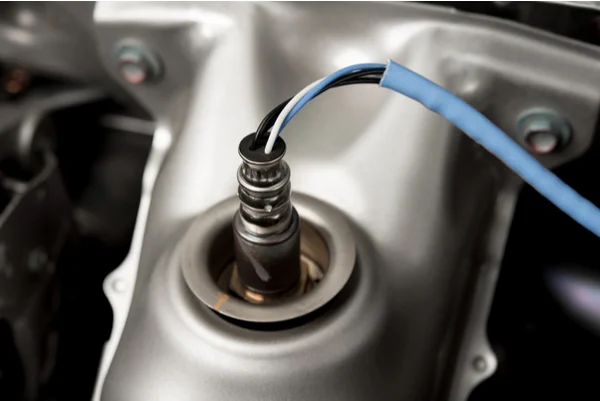
In simple terms, the OBD II code P1131, when displayed on your Ford Vehicle, indicates the PCM detected a malfunction. By estimating the O2 amount, the PCM assesses whether the engine is running on a rich or lean fuel mixture. A lean mixture can give rise to various problems and thus displays the code P1131.
Whereas, an optimized fuel mixture is preferred because of the following-
- Better Fuel Economy
- Better Acceleration
- Reduced tailpipe emissions
- Prolonged engine life
In contrast, an engine running on a lean mixture can give rise to many issues that can appear combinedly or separately. That is discussed in the coming sections.
Some of The Other OBD II Codes That Are Related to P1131 on Ford Vehicles are-
- P1137
- P1151
- P1157
- P0171
- P0174
Symptoms of P1131 on Ford
The most visible symptoms of the P1131 code is-
- Check Engine light ‘ON.’
- Slow Acceleration
- Poor fuel economy
- Car Unable to Start
Moreover, there are some other symptoms for the P1131 code on Ford. But, the chances of encountering them are minimal-
- Engine Stalling
- Engine Knocking
- A rise in Exhaust gas Emissions
- Engine frequently misfires
Causes of P1131 on Ford

There can be various causes for the error code P1131-
1. Fuel System Malfunctioning
Issues in the Injectors, fuel filter, pump, etc., can result in a low quantity of fuel reaching the combustion chamber. The components listed below collectively or individually can cause Fuel System Malfunctioning-
- Clogged Fuel filter: This may create a barrier to fuel passing the filter during the filtering process, thus creating a lean mixture.
- Defective Fuel Pump: A lean mixture can be formed due to the fuel pump’s inability to supply the fuel with the required optimal pressure.
- Faulty Fuel Injectors: The injectors are responsible for spraying the fuel into the combustion chamber. If they start to leak or become dirty, it may result in an interrupted fuel injection into the cylinder. The injectors with low pressure can result in the formation of a lean mixture.
2. Oxygen Sensor Inaccuracy
At times, it is possible that the sensor responsible for measuring the O2 in the cylinder malfunctions. Thus, reporting more oxygen in the mixture than the actual quantity. The amount of oxygen is proportional to the air quantity supplied. As a result, the PCM may display a lean mixture. Thus displaying the P1131 code.
3. Air Mass Flow Sensor Inaccuracy
The Air Mass Flow sensor estimates the amount of air that’s entering the cylinder. A faulty Air mass flow sensor may inaccurately assess the quantity of incoming air. Thus, as a result, the P1131 code may be displayed on the Ford vehicle.
4. Computer Malfunction
Though the chances of malfunctioning of an on-board computer are very low, however, a faulty on-board diagnostics system can inaccurately display the P1131 code.
5. Air Leaks
Innumerable hoses and gaskets are employed in an engine. These components are not built to last forever. Hence, it is possible due to incessant exposure to heat and pressure; any of these components gives rise to air leaks. Thus, air leaks can find its way into the engine, assisting in the formation of a lean mixture.
How Serious is P1131OBD II Code on Ford
Though the issues causing the P1131 code may not impact your vehicle’s functioning. However, if ignored, these can cause severe damage to other vital components in the long term.
A regular check-up or servicing might help to resolve the problems responsible for OBD II code P1131. Additionally, looking for the causes mentioned above can help fathom the issue much faster and easier.
Can You Drive with p1131?
It is not recommended to drive your Ford while the P1131 code is being displayed.
A petrol engine running on a lean mixture can cause problems like-
- Reduced Performance
- Engine Knocking (Inconsistent fuel combustion)
- Damage to Piston
A Diesel engine running on a lean mixture may not result in the same problems but still can cause-
- Low Output from engine
- Engine Stalling
However, the vehicle with the P1131 code can cause sudden jerks with lagging acceleration. Moreover, it may reduce the efficiency of the vehicle while increasing emissions.
Tools Needed to Fix any of these Issues-
How to Fix the Code P1131 on Ford?
The first and foremost thing to be done when checking for the causes of the P1131 code is to connect a car diagnostic scanner to the car’s OBD. Running a diagnostic scan can give comprehensive information on the malfunctioned system to help resolve the issue promptly.
Moreover, if running an OBD diagnostics does not helps then, follow these steps to fix the code P1131-
Step 1– Check and Replace any damaged engine air-intake hoses
Step 2– Tighten the Spark Plugs Connecting Wires
Step 3– Check and Resolve any issue with Distributor assembly, like rotor or cap
Step 4– Check any fault in the fuel supply
Step 5– Lastly, but importantly check the wiring and connection of the Oxygen Sensor.
If the issue still goes undetected, then visiting a service center might help.
Tips to Avoid p1131 in the Future
Here are a few Tips to Avoid OBD II Code P1131-
- Servicing your Ford F150/ Ford Ranger/ Ford Taurus/ Ford Explorer/ Ford Expedition/ Ford Mustang/ Ford Escort regularly
- Replacing worn off engine gaskets and hoses
- Monitoring the fuel injection pressure from the injectors
- Checking for any Engine air leaks
Frequently Asked Questions
Q) Why do lambda (oxygen) sensors fail?
- Lambda sensor is continuously exposed to the high temperature of exhaust gases. Thus heat and vibration can cause damage to the wirings and connections. Moreover, the lambda sensor can be faulty due to corrosion as well.
Q) What happens if my O2 sensor is damaged?
- A damaged O2 sensor doesn’t cause any serious problems. You can even drive with a bad O2 sensor. However, it may hamper other engine components in the long term and can even affect the overall vehicle’s performance.
Q) My Ford is driving fine, but it shows code P1131?
- This could be because of the malfunction of any of the components responsible for diagnostics, or your Ford is driving fine because the issue is still in its initial phase and can increase over time.
Read more : 9 Best Ford/Mazda OBD2/OBD1 Scan Tools for 2024
Mercedes Fault Codes List For Diagnosing Issues
Mercedes Fault Codes List For Diagnosing Issues
Are you ready to take control of your Mercedes destiny? Our Mercedes Fault Codes List is your passport to understanding your car messages.
From OBD1 to OBD2 codes, our expertly curated list covers a wide range of fault codes and gains the knowledge you need to address these codes effectively.
Let’s explore the world of Mercedes fault codes together!
Mercedes OBD1 Codes List And Definition [FULL]
Free download: Full Mercedes OBD1 Trouble Codes List and Meaning PDF
We’ve categorized the OBD1 codes list into three parts, providing you with a comprehensive resource for easier troubleshooting and targeted diagnostics specific to your Mercedes vehicle.
Note: Utilize the search box in the table below to quickly find the specific code you’re looking for.
90-93 190E & 300 Series (2.3L)
| Code | Definition |
|---|---|
| Code 1 | No System Malfunction |
| Code 2 | Throttle Valve Switch |
| Code 3 | Coolant Temp Sensor |
| Code 4 | Airflow Sensor Position Indicator |
| Code 5 | Oxygen Sensor |
| Code 6 | Not Used |
| Code 7 | Td Signal |
| Code 8 | Altitude Correction Capsule |
| Code 9 | Electro-Hydraulic Actuator (EHA) |
| Code 10 | Throttle Valve Switch And/Or Idle Speed Contact |
| Code 11 | Not Used |
| Code 12 | EGR Temp Sensor |
91 & Later 300 Series (2.8L And 3.2L)
| Code | Definition |
|---|---|
| Code 1 | No Faults |
| Code 2 | Oxygen Sensor Inoperative |
| Code 3 | Lambda Control Inoperative |
| Code 4 | Air Injection Inoperative |
| Code 5 | EGR Inoperative |
| Code 6 | Idle Speed Control Inoperative |
| Code 7 | Ignition System Failure |
| Code 8 | Coolant Temp Sensor-Open Or Short Circuit |
| Code 9 | Intake Air Temp Sensor-Open Or Short Circuit |
| Code 10 | Voltage At Air Mass Sensor Too High Or Low |
| Code 11 | TN (RPM) Signal Defective |
| Code 12 | Oxygen Sensor Heater Open Or Short Circuit |
| Code 13 | Cam Position Sensor Signal From-EZL/AKR Ign Control Unit Defective |
| Code 14 | Intake Manifold Pressure At Start Too Low |
| Code 15 | Full Throttle Info Defective |
| Code 16 | Idle Speed Info Defective |
| Code 17 | CAN Data Exchange-Malfunction Between Control Units |
| Code 18 | Adjustable Camshaft Timing Solenoid-Open Or Short Circuit |
| Code 19 | Fuel Injectors-Open Or Short Circuit Or Emission Control System Adaptation At Limit |
| Code 20 | Speed Signal Missing |
| Code 21 | Purge Switchover Valve-Open Or Shorted |
| Code 22 | Cam Position Sensor Signal Defective |
| Code 23 | Intake Manifold Pressure W/ Engine Running Too Low |
| Code 24 | Starter Ring Gear Segments Defective |
| Code 25 | Knock Sensors |
| Code 26 | Upshift Delay Switch Over Valve-Open Or Shorted |
| Code 27 | Coolant Temp Sensor Deviation Between Sensor Ciruits 1 & 2 |
| Code 28 | Coolant Temp Sensor |
91-93 190E And 300 Series (2.6L And 3.0L)
| Code | Definition |
|---|---|
| Code 1 | No Faults In System |
| Code 2 | Throttle Valve Switch(Full Throttle Contact) |
| Code 3 | Coolant Temp Sensor |
| Code 4 | Airflow Sensor Potentiometer |
| Code 5 | Oxygen Sensor |
| Code 7 | TNA (RPM) Signal |
| Code 8 | Altitude Pressure Signal From EZL Ignition Control Unit |
| Code 9 | Current To Electro-Hydraulic Actuator |
| Code 10 | Throttle Valve Switch(Idle Contact) |
| Code 11 | Air Injection System |
| Code 12 | Absolute Pressure Valves From ELZ Ignition Control Unit |
| Code 13 | Intake Air Temp Signal |
| Code 14 | Road Speed Signal At CIS-E Control Unit |
| Code 16 | EGR |
| Code 17 | Oxygen Sensor Signal |
| Code 18 | Current To Idle Speed Air Valve |
| Code 22 | Oxygen Sensor Heating Current |
| Code 23 | Short To Positive In Regeneration Switch Over Valve Circuit |
| Code 25 | Short To Positive In Start Valve Circuit |
| Code 26 | Short To Positive In Shift Point Retard Circuit |
| Code 27 | Data Exchange Fault Between CIS-E Control Unit And EZL Ignition Control Unit |
| Code 28 | Loose Contact In Coolant Temp Sensorcircuit |
| Code 29 | Difference In Coolant Temps Between CIS-Eunit And EZL Unit |
| Code 31 | Loose Contact In Intake Air Temp Sensor Circuit |
| Code 34 | Faulty Coolant Temp Sensor Signal From EZL Unit |
Mercedes OBD2 Codes List and Definition [FULL]
Free download: Full Mercedes OBD2 Trouble Codes List and Meaning PDF
Our user-friendly code list is divided into four sections: Powertrain, Network, Body, and Chassis. This categorization simplifies your search for codes related to engine, network, body control, and chassis issues.
Note: Utilize the search box in the table below to quickly find the specific code you’re looking for.
Powertrain (P) Codes List
| Code | Definition |
|---|---|
| P0010 | “A” Camshaft Position Actuator Circuit (Bank 1) |
| P0011 | “A” Camshaft Position – Timing Over-Advanced or System Performance (Bank 1) |
| P0012 | “A” Camshaft Position – Timing Over-Retarded (Bank 1) |
| P0013 | “B” Camshaft Position – Actuator Circuit (Bank 1) |
| P0014 | “B” Camshaft Position – Timing Over-Advanced or System Performance (Bank 1) |
| P0015 | “B” Camshaft Position -Timing Over-Retarded (Bank 1) |
| P0020 | “A” Camshaft Position Actuator Circuit (Bank 2) |
| P0021 | “A” Camshaft Position – Timing Over-Advanced or System Performance (Bank 2) |
| P0022 | “A” Camshaft Position – Timing Over-Retarded (Bank 2) |
| P0023 | “B” Camshaft Position – Actuator Circuit (Bank 2) |
| P0024 | “B” Camshaft Position – Timing Over-Advanced or System Performance (Bank 2) |
| P0025 | “B” Camshaft Position – Timing Over-Retarded (Bank 2) |
| P0030 | HO2S Heater Control Circuit (Bank 1 Sensor 1) |
| P0031 | HO2S Heater Control Circuit Low (Bank 1 Sensor 1) |
| P0032 | HO2S Heater Control Circuit High (Bank 1 Sensor 1) |
| P0033 | Turbo Charger Bypass Valve Control Circuit |
| P0034 | Turbo Charger Bypass Valve Control Circuit Low |
| P0035 | Turbo Charger Bypass Valve Control Circuit High |
| P0036 | HO2S Heater Control Circuit (Bank 1 Sensor 2) |
| P0037 | HO2S Heater Control Circuit Low (Bank 1 Sensor 2) |
| P0038 | HO2S Heater Control Circuit High (Bank 1 Sensor 2) |
| P0042 | HO2S Heater Control Circuit (Bank 1 Sensor 3) |
| P0043 | HO2S Heater Control Circuit Low (Bank 1 Sensor 3) |
| P0044 | HO2S Heater Control Circuit High (Bank 1 Sensor 3) |
| P0050 | HO2S Heater Control Circuit (Bank 2 Sensor 1) |
| P0051 | HO2S Heater Control Circuit Low (Bank 2 Sensor 1) |
| P0052 | HO2S Heater Control Circuit High (Bank 2 Sensor 1) |
| P0056 | HO2S Heater Control Circuit (Bank 2 Sensor 2) |
| P0057 | HO2S Heater Control Circuit Low (Bank 2 Sensor 2) |
| P0058 | HO2S Heater Control Circuit High (Bank 2 Sensor 2) |
| P0062 | HO2S Heater Control Circuit (Bank 2 Sensor 3) |
| P0063 | HO2S Heater Control Circuit Low (Bank 2 Sensor 3) |
| P0064 | HO2S Heater Control Circuit High (Bank 2 Sensor 3) |
| P0065 | Air Assisted Injector Control Range/Performance |
| P0066 | Air Assisted Injector Control Circuit or Circuit Low |
| P0067 | Air Assisted Injector Control Circuit High |
| P0070 | Ambient Air Temperature Sensor Circuit |
| P0071 | Ambient Air Temperature Sensor Range/Performance |
| P0072 | Ambient Air Temperature Sensor Circuit Low Input |
| P0073 | Ambient Air Temperature Sensor Circuit High Input |
| P0074 | Ambient Air Temperature Sensor Circuit Intermittent |
| P0075 | Intake Valve Control Solenoid Circuit (Bank 1) |
| P0076 | Intake Valve Control Solenoid Circuit Low (Bank 1) |
| P0077 | Intake Valve Control Solenoid Circuit High (Bank 1) |
| P0078 | Exhaust Valve Control Solenoid Circuit (Bank 1) |
| P0079 | Exhaust Valve Control Solenoid Circuit Low (Bank 1) |
| P0080 | Exhaust Valve Control Solenoid Circuit High (Bank 1) |
| P0081 | Intake valve Control Solenoid Circuit (Bank 2) |
| P0082 | Intake Valve Control Solenoid Circuit Low (Bank 2) |
| P0083 | Intake Valve Control Solenoid Circuit High (Bank 2) |
| P0084 | Exhaust Valve Control Solenoid Circuit (Bank 2) |
| P0085 | Exhaust Valve Control Solenoid Circuit Low (Bank 2) |
| P0086 | Exhaust Valve Control Solenoid Circuit High (Bank 2) |
| P0100 | Mass or Volume Air Flow Circuit |
| P0101 | Mass or Volume Air Flow Circuit Range/Performance Problem |
| P0102 | Mass or Volume Air Flow Circuit Low Input |
| P0103 | Mass or Volume Air Flow Circuit High Input |
| P0104 | Mass or Volume Air Flow Circuit Intermittent |
| P0105 | Manifold Absolute Pressure/Barometric Pressure Circuit |
| P0106 | Manifold Absolute Pressure/Barometric Pressure Circuit Range/Performance Problem |
| P0107 | Manifold Absolute Pressure/Barometric Pressure Circuit Low Input |
| P0108 | Manifold Absolute Pressure/Barometric Pressure Circuit High Input |
| P0109 | Manifold Absolute Pressure/Barometric Pressure Circuit Intermittent |
| P0110 | Intake Air Temperature Circuit |
| P0111 | Intake Air Temperature Circuit Range/Performance Problem |
| P0112 | Intake Air Temperature Circuit Low Input |
| P0113 | Intake Air Temperature Circuit High Input |
| P0114 | Intake Air Temperature Circuit Intermittent |
| P0115 | Engine Coolant Temperature Circuit |
| P0116 | Engine Coolant Temperature Circuit Range/Performance Problem |
| P0117 | Engine Coolant Temperature Circuit Low Input |
| P0118 | Engine Coolant Temperature Circuit High Input |
| P0119 | Engine Coolant Temperature Circuit Intermittent |
| P0120 | Throttle/Pedal Position Sensor/Switch A Circuit |
| P0121 | Throttle/Pedal Position Sensor/Switch A Circuit Range/Performance Problem |
| P0122 | Throttle/Pedal Position Sensor/Switch A Circuit Low Input |
| P0123 | Throttle/Pedal Position Sensor/Switch A Circuit High Input |
| P0124 | Throttle/Pedal Position Sensor/Switch A Circuit Intermittent |
| P0125 | Insufficient Coolant Temperature for Closed Loop Fuel Control |
| P0126 | Insufficient Coolant Temperature for Stable Operation |
| P0127 | Intake Air Temperature Too High |
| P0128 | Coolant Thermostat (Coolant Temperature Below Thermostat Regulating Temperature) |
| P0130 | O2 Sensor Circuit (Bank 1 Sensor 1) |
| P0131 | O2 Sensor Circuit Low Voltage (Bank 1 Sensor 1) |
| P0132 | O2 Sensor Circuit High Voltage (Bank 1 Sensor 1) |
| P0133 | O2 Sensor Circuit Slow Response (Bank 1 Sensor 1) |
| P0134 | O2 Sensor Circuit No Activity Detected (Bank 1 Sensor 1) |
| P0135 | O2 Sensor Heater Circuit (Bank 1 Sensor 1) |
| P0136 | O2 Sensor Circuit Malfunction (Bank 1 Sensor 2) |
| P0137 | O2 Sensor Circuit Low Voltage (Bank 1 Sensor 2) |
| P0138 | O2 Sensor Circuit High Voltage (Bank 1 Sensor 2) |
| P0139 | O2 Sensor Circuit Slow Response (Bank 1 Sensor 2) |
| P0140 | O2 Sensor Circuit No Activity Detected (Bank 1 Sensor 2) |
| P0141 | O2 Sensor Heater Circuit (Bank 1 Sensor 2) |
| P0142 | O2 Sensor Circuit Malfunction (Bank 1 Sensor 3) |
| P0143 | O2 Sensor Circuit Low Voltage (Bank 1 Sensor 3) |
| P0144 | O2 Sensor Circuit High Voltage (Bank 1 Sensor 3) |
| P0145 | O2 Sensor Circuit Slow Response (Bank 1 Sensor 3) |
| P0146 | O2 Sensor Circuit No Activity Detected (Bank 1 Sensor 3) |
| P0147 | O2 Sensor Heater Circuit (Bank 1 Sensor 3) |
| P0148 | Fuel Delivery Error |
| P0149 | Fuel Timing Error |
| P0150 | O2 Sensor Circuit (Bank 2 Sensor 1) |
| P0151 | O2 Sensor Circuit Low Voltage (Bank 2 Sensor 1) |
| P0152 | O2 Sensor Circuit High Voltage (Bank 2 Sensor 1) |
| P0153 | O2 Sensor Circuit Slow Response (Bank 2 Sensor 1) |
| P0154 | O2 Sensor Circuit No Activity Detected (Bank 2 Sensor 1) |
| P0155 | O2 Sensor Heater Circuit (Bank 2 Sensor 1) |
| P0156 | O2 Sensor Circuit Malfunction (Bank 2 Sensor 2) |
| P0157 | O2 Sensor Circuit Low Voltage (Bank 2 Sensor 2) |
| P0158 | O2 Sensor Circuit High Voltage (Bank 2 Sensor 2) |
| P0159 | O2 Sensor Circuit Slow Response (Bank 2 Sensor 2) |
| P0160 | O2 Sensor Circuit No Activity Detected (Bank 2 Sensor 2) |
| P0161 | O2 Sensor Heater Circuit (Bank 2 Sensor 2) |
| P0162 | O2 Sensor Circuit Malfunction (Bank 2 Sensor 3) |
| P0163 | O2 Sensor Circuit Low Voltage (Bank 2 Sensor 3) |
| P0164 | O2 Sensor Circuit High Voltage (Bank 2 Sensor 3) |
| P0165 | O2 Sensor Circuit Slow Response (Bank 2 Sensor 3) |
| P0166 | O2 Sensor Circuit No Activity Detected (Bank 2 Sensor 3) |
| P0167 | O2 Sensor Heater Circuit (Bank 2 Sensor 3) |
| P0168 | Fuel Temperature Too High |
| P0169 | Incorrect Fuel Composition |
| P0170 | Fuel Trim (Bank 1) |
| P0171 | System too Lean (Bank 1) |
| P0172 | System too Rich (Bank 1) |
| P0173 | Fuel Trim Malfunction (Bank 2) |
| P0174 | System too Lean (Bank 2) |
| P0175 | System too Rich (Bank 2) |
| P0176 | Fuel Composition Sensor Circuit |
| P0177 | Fuel Composition Sensor Circuit Range/Performance |
| P0178 | Fuel Composition Sensor Circuit Low Input |
| P0179 | Fuel Composition Sensor Circuit High Input |
| P0180 | Fuel Temperature Sensor A Circuit |
| P0181 | Fuel Temperature Sensor A Circuit Range/Performance |
| P0182 | Fuel Temperature Sensor A Circuit Low Input |
| P0183 | Fuel Temperature Sensor A Circuit High Input |
| P0184 | Fuel Temperature Sensor A Circuit Intermittent |
| P0185 | Fuel Temperature Sensor B Circuit |
| P0186 | Fuel Temperature Sensor B Circuit Range/Performance |
| P0187 | Fuel Temperature Sensor B Circuit Low Input |
| P0188 | Fuel Temperature Sensor B Circuit High Input |
| P0189 | Fuel Temperature Sensor B Circuit Intermittent |
| P0190 | Fuel Rail Pressure Sensor Circuit |
| P0191 | Fuel Rail Pressure Sensor Circuit Range/Performance |
| P0192 | Fuel Rail Pressure Sensor Circuit Low In put |
| P0193 | Fuel Rail Pressure Sensor Circuit High Input |
| P0194 | Fuel Rail Pressure Sensor Circuit Intermittent |
| P0195 | Engine Oil Temperature Sensor |
| P0196 | Engine Oil Temperature Sensor Range/Performance |
| P0197 | Engine Oil Temperature Sensor Low |
| P0198 | Engine Oil Temperature Sensor High |
| P0199 | Engine Oil Temperature Sensor Intermittent |
| P01XX | Fuel and Air Metering |
| P0200 | Injector Circuit |
| P0201 | Injector Circuit – Cylinder 1 |
| P0202 | Injector Circuit – Cylinder 2 |
| P0203 | Injector Circuit – Cylinder 3 |
| P0204 | Injector Circuit – Cylinder 4 |
| P0205 | Injector Circuit – Cylinder 5 |
| P0206 | Injector Circuit – Cylinder 6 |
| P0207 | Injector Circuit – Cylinder 7 |
| P0208 | Injector Circuit – Cylinder 8 |
| P0209 | Injector Circuit – Cylinder 9 |
| P0210 | Injector Circuit – Cylinder 10 |
| P0211 | Injector Circuit – Cylinder 11 |
| P0212 | Injector Circuit – Cylinder 12 |
| P0213 | Cold Start Injector 1 |
| P0214 | Cold Start Injector 2 |
| P0215 | Engine Shutoff Solenoid |
| P0216 | Injector/Injection Timing Control Circuit |
| P0217 | Engine Coolant Over Temperature Condition |
| P0218 | Transmission Fluid Over Temperature Condition |
| P0219 | Engine Over Speed Condition |
| P0220 | Throttle/Pedal Position Sensor/Switch “B” Circuit |
| P0221 | Throttle/Pedal Position Sensor/Switch “B” Circuit Range/Performance Problem |
| P0222 | Throttle/Pedal Position Sensor/Switch “B” Circuit Low Input |
| P0223 | Throttle/Pedal Position Sensor/Switch “B” Circuit High Input |
| P0224 | Throttle/Pedal Position Sensor/Switch “B” Circuit Intermittent |
| P0225 | Throttle/Pedal Position Sensor/Switch “C” Circuit |
| P0226 | Throttle/Pedal Position Sensor/Switch “C” Circuit Range/Performance Problem |
| P0227 | Throttle/Pedal Position Sensor/Switch “C” Circuit Low Input |
| P0228 | Throttle/Pedal Position Sensor/Switch “C” Circuit High Input |
| P0229 | Throttle/Pedal Position Sensor/Switch “C” Circuit Intermittent |
| P0230 | Fuel Pump Primary Circuit |
| P0231 | Fuel Pump Secondary Circuit Low |
| P0232 | Fuel Pump Secondary Circuit High |
| P0233 | Fuel Pump Secondary Circuit Intermittent |
| P0234 | Turbo/Super Charger Overboost Condition |
| P0235 | Turbo/Super Charger Boost Sensor “A” Circuit |
| P0236 | Turbo/Super Charger Boost Sensor “A” Circuit Range/Performance |
| P0237 | Turbo/Super Charger Boost Sensor “A” Circuit Low |
| P0238 | Turbo/Super Charger Boost Sensor “A” Circuit High |
| P0239 | Turbo/Super Charger Boost Sensor “B” Circuit |
| P0240 | Turbo/Super Charger Boost Sensor “B” Circuit Range/Performance |
| P0241 | Turbo/Super Charger Boost Sensor “B” Circuit Low |
| P0242 | Turbo/Super Charger Boost Sensor “B” Circuit High |
| P0243 | Turbo/Super Charger Wastegate Solenoid “A” |
| P0244 | Turbo/Super Charger Wastegate Solenoid “A” Range/Performance |
| P0245 | Turbo/Super Charger Wastegate Solenoid “A” Low |
| P0246 | Turbo/Super Charger Wastegate Solenoid “A” High |
| P0247 | Turbo/Super Charger Wastegate Solenoid “B” |
| P0248 | Turbo/Super Charger Wastegate Solenoid “B” Range/Performance |
| P0249 | Turbo/Super Charger Wastegate Solenoid “B” Low |
| P0250 | Turbo/Super Charger Wastegate Solenoid “B” High |
| P0251 | Injection Pump Fuel Metering Control “A” (Cam/rotor/Injector) |
| P0252 | Injection Pump Fuel Metering Control “A” Range/Performance (Cam/Rotor/Injector) |
| P0253 | Injection Pump Fuel Metering Control “A” Low (Cam/Rotor/Injector) |
| P0254 | Injection Pump Fuel Metering Control “A” High (Cam/Rotor/Injector) |
| P0255 | Injection Pump Fuel Metering Control “A” Intermittent (Cam/Rotor/Injector) |
| P0256 | Injection Pump Fuel Metering Control “B” (Cam/Rotor/Injector) |
| P0257 | Injection Pump Fuel Metering Control “B” Range/Performance (Cam/Rotor/Injector) |
| P0258 | Injection Pump Fuel Metering Control “B” Low (Cam/Rotor/Injector) |
| P0259 | Injection Pump Fuel Metering Control “B” High (Cam/Rotor/Injector) |
| P0260 | Injection Pump Fuel Metering Control “B” Intermittent (Cam/Rotor/Injector) |
| P0261 | Cylinder 1 Injector Circuit Low |
| P0262 | Cylinder 1 Injector Circuit High |
| P0263 | Cylinder 1 Contribution/Balance |
| P0264 | Cylinder 2 Injector Circuit Low |
| P0265 | Cylinder 2 Injector Circuit High |
| P0266 | Cylinder 2 Contribution/Balance |
| P0267 | Cylinder 3 Injector Circuit Low |
| P0268 | Cylinder 3 Injector Circuit High |
| P0269 | Cylinder 4 Contribution/Balance |
| P0270 | Cylinder 4 Injector Circuit Low |
| P0271 | Cylinder 4 Injector Circuit High |
| P0272 | Cylinder 4 Contribution/Balance |
| P0273 | Cylinder 5 Injector Circuit Low |
| P0274 | Cylinder 5 Injector Circuit High |
| P0275 | Cylinder 5 Contribution/Balance |
| P0276 | Cylinder 6Injector Circuit Low |
| P0277 | Cylinder 6 Injector Circuit High |
| P0278 | Cylinder 6 Contribution/Balance |
| P0279 | Cylinder 7 Injector Circuit Low |
| P0280 | Cylinder 7 Injector Circuit High |
| P0281 | Cylinder 7 Contribution/Balance |
| P0282 | Cylinder 8 Injector Circuit Low |
| P0283 | Cylinder 8 Injector Circuit High |
| P0284 | Cylinder 8 Contribution/Balance |
| P0285 | Cylinder 9 Injector Circuit Low |
| P0286 | Cylinder 9 Injector Circuit High |
| P0287 | Cylinder 9 Contribution/Balance |
| P0288 | Cylinder 10 Injector Circuit Low |
| P0289 | Cylinder 10 Injector Circuit High |
| P0290 | Cylinder 10 Contribution/Balance |
| P0291 | Cylinder 11 Injector Circuit Low |
| P0292 | Cylinder 11 Injector Circuit High |
| P0293 | Cylinder 11 Contribution/Balance |
| P0294 | Cylinder 12 Injector Circuit Low |
| P0295 | Cylinder 12 Injector Circuit High |
| P0296 | Cylinder 12 Contribution/Balance |
| P0298 | Engine Oil Over Temperature |
| P02XX | Fuel and Air Metering |
| P0300 | Random/Multiple Cylinder Misfire Detected |
| P0301 | Cylinder 1 Misfire Detected |
| P0302 | Cylinder 2 Misfire Detected |
| P0303 | Cylinder 3 Misfire Detected |
| P0304 | Cylinder 4 Misfire Detected |
| P0305 | Cylinder 5 Misfire Detected |
| P0306 | Cylinder 6 Misfire Detected |
| P0307 | Cylinder 7 Misfire Detected |
| P0308 | Cylinder 8 Misfire Detected |
| P0309 | Cylinder 9 Misfire Detected |
| P0310 | Cylinder 10 Misfire Detected |
| P0311 | Cylinder 11 Misfire Detected |
| P0312 | Cylinder 12 Misfire Detected |
| P0313 | Misfire Detected with Low Fuel |
| P0314 | Single Cylinder Misfire (Cylinder not Specified) |
| P0320 | Ignition/Distributor Engine Speed Input Circuit |
| P0321 | Ignition/Distributor Engine Speed Input Circuit Range/Performance |
| P0322 | Ignition/Distributor Engine Speed Input Circuit No Signal |
| P0323 | Ignition/Distributor Engine Speed Input Circuit Intermittent |
| P0324 | Knock Control System Error |
| P0325 | Knock Sensor 1 Circuit (Bank 1 or Single Sensor) |
| P0326 | Knock Sensor 1 Circuit Range/Performance (Bank 1 or Single Sensor) |
| P0327 | Knock Sensor 1 Circuit Low Input (Bank 1 or Single Sensor) |
| P0328 | Knock Sensor 1 Circuit High Input (Bank 1 or Single Sensor) |
| P0329 | Knock Sensor 1 Circuit Input Intermittent (Bank 1 or Single Sensor) |
| P0330 | Knock Sensor 2 Circuit (Bank 2) |
| P0331 | Knock Sensor 2 Circuit Range/Performance (Bank 2) |
| P0332 | Knock Sensor 2 Circuit Low Input (Bank 2) |
| P0333 | Knock Sensor 2 Circuit High Input (Bank 2) |
| P0334 | Knock Sensor 2 Circuit Input Intermittent (Bank 2) |
| P0335 | Crankshaft Position Sensor A Circuit |
| P0336 | Crankshaft Position Sensor A Circuit Range/Performance |
| P0337 | Crankshaft Position Sensor A Circuit Low Input |
| P0338 | Crankshaft Position Sensor A Circuit High Input |
| P0339 | Crankshaft Position Sensor A Circuit Intermittent |
| P0340 | Camshaft Position Sensor “A” Circuit (Bank 1 or Single Sensor) |
| P0341 | Camshaft Position Sensor “A” Circuit Range/Performance (Bank 1 or Single Sensor) |
| P0342 | Camshaft Position Sensor “A” Circuit Low Input (Bank 1 or Single Sensor) |
| P0343 | Camshaft Position Sensor “A” Circuit High Input (Bank 1 or Single Sensor) |
| P0344 | Camshaft Position Sensor “A” Circuit Intermittent (Bank 1 or Single Sensor) |
| P0345 | Camshaft Position Sensor “A” Circuit (Bank 2) |
| P0347 | Camshaft Position Sensor “A” Circuit Low Input (Bank 2) |
| P0348 | Camshaft Position Sensor “A” Circuit Range/Performance (Bank 2) |
| P0348 | Camshaft Position Sensor “A” Circuit High Input (Bank 2) |
| P0349 | Camshaft Position Sensor “A” Circuit Intermittent (Bank 2) |
| P0350 | Ignition Coil Primary/Secondary Circuit |
| P0351 | Ignition Coil “A” Primary/Secondary Circuit |
| P0352 | Ignition Coil “B” Primary/Secondary Circuit |
| P0353 | Ignition Coil “C” Primary/Secondary Circuit |
| P0354 | Ignition Coil “D” Primary/Secondary Circuit |
| P0355 | Ignition Coil “F” Primary/Secondary Circuit |
| P0356 | Ignition Coil “F” Primary/Secondary Circuit |
| P0357 | Ignition Coil “G” Primary/Secondary Circuit |
| P0358 | Ignition Coil “H” Primary/Secondary Circuit |
| P0359 | Ignition Coil “I” Primary/Secondary Circuit |
| P0360 | Ignition Coil “J” Primary/Secondary Circuit |
| P0361 | Ignition Coil “K Primary/Secondary Circuit |
| P0362 | Ignition Coil “L’ Primary/Secondary Circuit |
| P0365 | Camshaft Position Sensor “B” Circuit (Bank 1) |
| P0366 | Camshaft Position Sensor “B” Circuit Range/Performance (Bank 1) |
| P0367 | Camshaft Position Sensor “B” Circuit Low Input (Bank 1) |
| P0368 | Camshaft Position Sensor “B” Circuit High Input (Bank 1) |
| P0369 | Camshaft Position Sensor “B” Circuit Intermittent (Bank 1) |
| P0370 | Timing Reference High Resolution Signal “A” |
| P0371 | Timing Reference High Resolution Signal “A” Too Many Pulses |
| P0372 | Timing Reference High Resolution Signal “A” Too Few Pulses |
| P0373 | Timing Reference High Resolution Signal “A” Intermittent/Erratic Pulses |
| P0374 | Timing Reference High Resolution Signal “A” No Pulse |
| P0375 | Timing Reference High Resolution Signal “B” |
| P0376 | Timing Reference High Resolution Signal “B” Too Many Pulses |
| P0377 | Timing Reference High Resolution Signal “B” Too Few Pulses |
| P0378 | Timing Reference High Resolution Signal “B” Intermittent/Erratic Pulses |
| P0379 | Timing Reference High Resolution Signal “B” No Pulses |
| P0380 | Glow Plug/Heater Circuit “A” |
| P0381 | Glow Plug/Heater Indicator Circuit |
| P0382 | Glow Plug/Heater Circuit “B” |
| P0385 | Crankshaft Position Sensor “B” Circuit |
| P0386 | Crankshaft Position Sensor “B” Circuit Range/Performance |
| P0387 | Crankshaft Position Sensor “B” Circuit Low Input |
| P0388 | Crankshaft Position Sensor “B” Circuit High Input |
| P0389 | Crankshaft Position Sensor “B” Circuit Intermittent |
| P0390 | Camshaft Position Sensor “B” Circuit |
| P0391 | Camshaft Position Sensor “B” circuit Range/Performance (Bank 2) |
| P0392 | Camshaft Position Sensor “B” Circuit Low Input (Bank 2) |
| P0393 | Camshaft Position Sensor “B” Circuit High Input (Bank 2) |
| P0394 | Camshaft Position Sensor “B” Circuit Intermittent (Bank 2) |
| P03XX | Ignition System or Misfire |
| P0400 | Exhaust Gas Recirculation Flow |
| P0401 | Exhaust Gas Recirculation Flow Insufficient Detected |
| P0402 | Exhaust Gas Recirculation Flow Excessive Detected |
| P0403 | Exhaust Gas Recirculation Control Circuit |
| P0404 | Exhaust Gas Recirculation Control Circuit Range/Performance |
| P0405 | Exhaust Gas Recirculation Sensor “A” Circuit Low |
| P0406 | Exhaust Gas Recirculation Sensor “A” Circuit High |
| P0407 | Exhaust Gas Recirculation Sensor “B” Circuit Low |
| P0408 | Exhaust Gas Recirculation Sensor “B” Circuit High |
| P0409 | Exhaust Gas Recirculation Sensor “A” Circuit |
| P0410 | Secondary Air Injection System |
| P0411 | Secondary Air Injection System Incorrect Flow Detected |
| P0412 | Secondary Air Injection System Switching Valve “A” Circuit |
| P0413 | Secondary Air Injection System Switching Valve “A” Circuit Open |
| P0414 | Secondary Air Injection System Switching Valve “A” Circuit Shorted |
| P0415 | Secondary Air Injection System Switching Valve “B” Circuit |
| P0416 | Secondary Air Injection System Switching Valve “B’ Circuit Open |
| P0416 | Secondary Air Injection System Relay “A” Circuit |
| P0417 | Secondary Air Injection System Switching Valve “B” Circuit Shorted |
| P0419 | Secondary Air injection System Relay “B” Circuit |
| P0420 | Catalyst System Efficiency Below Threshold (Bank 1) |
| P0421 | Warm Up Catalyst Efficiency Below Threshold (Bank 1) |
| P0422 | Main Catalyst Efficiency Below Threshold (Bank 1) |
| P0423 | Heated Catalyst Efficiency Below Threshold (Bank 1) |
| P0424 | Heated Catalyst Temperature Below Threshold (Bank 1) |
| P0425 | Catalyst Temperature Sensor (Bank 1) |
| P0426 | Catalyst Temperature Sensor Range/Performance (Bank 1) |
| P0427 | Catalyst Temperature Sensor Low Input (Bank 1) |
| P0428 | Catalyst Temperature Sensor High Input (Bank 1) |
| P0429 | Catalyst Heater Control Circuit (Bank 1) |
| P0430 | Catalyst System Efficiency Below Threshold (Bank 2) |
| P0431 | Warm Up Catalyst Efficiency Below Threshold (Bank 2) |
| P0432 | Main Catalyst Efficiency Below Threshold (Bank 2) |
| P0433 | Heated Catalyst Efficiency Below Threshold (Bank 2) |
| P0434 | Heated Catalyst Temperature Below Threshold (Bank 2) |
| P0435 | Catalyst Temperature Sensor (Bank 2) |
| P0436 | Catalyst Temperature Sensor Range/Performance (Bank 2) |
| P0437 | Catalyst Temperature Sensor Low Input (Bank 2) |
| P0438 | Catalyst Temperature Sensor High Input (Bank 2) |
| P0439 | Catalyst Heater Control Circuit (Bank 2) |
| P0440 | Evaporative Emission Control System |
| P0441 | Evaporative Emission Control System Incorrect Purge Flow |
| P0442 | Evaporative Emission Control System Leak Detected (small leak) |
| P0443 | Evaporative Emission Control System Purge Control Valve Circuit |
| P0444 | Evaporative Emission Control System Purge Control Valve Circuit Open |
| P0445 | Evaporative Emission Control System Purge Control Valve Circuit Shorted |
| P0446 | Evaporative Emission Control System Vent Control Circuit |
| P0447 | Evaporative Emission Control System Vent Control Circuit Open |
| P0448 | Evaporative Emission Control System Vent Control Circuit Shorted |
| P0449 | Evaporative Emission Control System Vent Valve/Solenoid Circuit |
| P0450 | Evaporative Emission Control System Pressure Sensor |
| P0451 | Evaporative Emission Control System Pressure Sensor Range/Performance |
| P0452 | Evaporative Emission Control System Pressure Sensor Low Input |
| P0453 | Evaporative Emission Control System Pressure Sensor High input |
| P0454 | Evaporative Emission Control System Pressure Sensor Intermittent |
| P0455 | Evaporative Emission Control System Leak Detected (gross leak) |
| P0456 | Evaporative Emission Control System Leak Detected (very small leak) |
| P0457 | Evaporative Emission Control System Leak Detected (fuel cap loose/off) |
| P0460 | Fuel Level Sensor Circuit |
| P0461 | Fuel Level Sensor Circuit Range/Performance |
| P0462 | Fuel Level Sensor Circuit Low Input |
| P0463 | Fuel Level Sensor Circuit High Input |
| P0464 | Fuel Level Sensor Circuit Intermittent |
| P0465 | EVAP Purge Flow Sensor Circuit |
| P0466 | Purge Flow Sensor Circuit Range/Performance |
| P0467 | Purge Flow Sensor Circuit Low Input |
| P0468 | Purge Flow Sensor Circuit High Input |
| P0469 | Purge Flow Sensor Circuit Intermittent |
| P0470 | Exhaust Pressure Sensor Malfunction |
| P0471 | Exhaust Pressure Sensor Range/Performance |
| P0472 | Exhaust Pressure Sensor Low |
| P0473 | Exhaust Pressure Sensor High |
| P0474 | Exhaust Pressure Sensor Intermittent |
| P0475 | Exhaust Pressure Control Valve Malfunction |
| P0476 | Exhaust Pressure Control Valve Range/Performance |
| P0477 | Exhaust Pressure Control Valve Low |
| P0478 | Exhaust Pressure Control Valve High |
| P0479 | Exhaust Pressure Control Valve Intermittent |
| P0480 | Cooling Fan 1 Control Circuit Malfunction |
| P0481 | Cooling Fan 2 Control Circuit Malfunction |
| P0482 | Cooling Fan 3 Control Circuit Malfunction |
| P0483 | Cooling Fan Rationality Check Malfunction |
| P0484 | Cooling Fan Circuit Over Current |
| P0485 | Cooling Fan Power/Ground Circuit Malfunction |
| P0486 | Exhaust Gas Recirculation Sensor “B” Circuit |
| P0487 | Exhaust Gas Recirculation Throttle Position Control Circuit |
| P0488 | Exhaust Gas Recirculation Throttle Position Control Range/Performance |
| P0491 | Secondary Air Injection System (Bank 1) |
| P0492 | Secondary Air Injection System (Bank 2) |
| P04XX | Auxiliary Emission Controls |
| P0500 | Vehicle Speed Sensor Malfunction |
| P0501 | Vehicle Speed Sensor Range/Performance |
| P0502 | Vehicle Speed Sensor Low Input |
| P0503 | Vehicle Speed Sensor Intermittent/Erratic/High |
| P0505 | Idle Control System Malfunction |
| P0506 | Idle Control System RPM Lower Than Expected |
| P0507 | Idle Control System RPM Higher Than Expected |
| P0508 | Idle Control System Circuit Low |
| P0509 | Idle Control System Circuit High |
| P0510 | Closed Throttle Position Switch Malfunction |
| P0510 | Closed Throttle Position Switch |
| P0512 | Starter Request Circuit |
| P0513 | Incorrect Irnmobilizer Key (“Immobilizer pending SAE J1930 approval) |
| P0515 | Battery Temperature Sensor Circuit |
| P0516 | Battery Temperature Sensor Circuit Low |
| P0517 | Battery Temperature Sensor Circuit High |
| P0520 | Engine Oil Pressure Sensor/Switch Circuit Malfunction |
| P0521 | Engine Oil Pressure Sensor/Switch Circuit Range/Performance |
| P0522 | Engine Oil Pressure Sensor/Switch Circuit Low Voltage |
| P0523 | Engine Oil Pressure Sensor/Switch Circuit High Voltage |
| P0524 | Engine Oil Pressure Too Low |
| P0530 | A/C Refrigerant Pressure Sensor Circuit Malfunction |
| P0531 | A/C Refrigerant Pressure Sensor Circuit Range/Performance |
| P0532 | A/C Refrigerant Pressure Sensor Circuit Low Input |
| P0533 | A/C Refrigerant Pressure Sensor Circuit High Input |
| P0534 | Air Conditioner Refrigerant Charge Loss |
| P0540 | Intake Air Heater Circuit |
| P0541 | Intake Air Heater Circuit Low |
| P0542 | Intake Air Heater Circuit High |
| P0544 | Exhaust Gas Temperature Sensor Circuit (Bank 1) |
| P0545 | Exhaust Gas Temperature Sensor Circuit Low (Bank 1) |
| P0546 | Exhaust Gas Temperature Sensor Circuit High (Bank 1) |
| P0547 | Exhaust Gas Temperature Sensor Circuit (Bank 2) |
| P0548 | Exhaust Gas Temperature Sensor Circuit Low (Bank 2) |
| P0549 | Exhaust Gas Temperature Sensor Circuit High (Bank 2) |
| P0550 | Power Steering Pressure Sensor Circuit Malfunction |
| P0551 | Power Steering Pressure Sensor Circuit Range/Performance |
| P0552 | Power Steering Pressure Sensor Circuit Low Input |
| P0553 | Power Steering Pressure Sensor Circuit High Input |
| P0554 | Power Steering Pressure Sensor Circuit Intermittent |
| P0560 | System Voltage Malfunction |
| P0561 | System Voltage Unstable |
| P0562 | System Voltage Low |
| P0563 | System Voltage High |
| P0565 | Cruise Control On Signal Malfunction |
| P0566 | Cruise Control Off Signal Malfunction |
| P0567 | Cruise Control Resume Signal Malfunction |
| P0568 | Cruise Control Set Signal Malfunction |
| P0569 | Cruise Control Coast Signal Malfunction |
| P0570 | Cruise Control Accel Signal Malfunction |
| P0571 | Cruise Control/Brake Switch A Circuit Malfunction |
| P0572 | Cruise Control/Brake Switch A Circuit Low |
| P0573 | Cruise Control/Brake Switch A Circuit High |
| P0574 | Cruise Control Related Malfunction |
| P0575 | Cruise Control Related Malfunction |
| P0576 | Cruise Control Related Malfunction |
| P0576 | Cruise Control Related Malfunction |
| P0578 | Cruise Control Related Malfunction |
| P0579 | Cruise Control Related Malfunction |
| P0580 | Cruise Control Related Malfunction |
| P0600 | Serial Communication Link Malfunction |
| P0601 | Internal Control Module Memory Check Sum Error |
| P0602 | Control Module Programming Error |
| P0603 | Internal Control Module Keep Alive Memory (KAM) Error |
| P0604 | Internal Control Module Random Access Memory (RAM) Error |
| P0605 | Internal Control Module Read Only Memory (ROM) Error |
| P0606 | PCM Processor Fault |
| P0608 | Control Module VSS Output “A” Malfunction |
| P0609 | Control Module VSS Output “B” Malfunction |
| P0610 | Control Module Vehicle Options Error |
| P0615 | Starter Relay Circuit |
| P0616 | Starter Relay Circuit Low |
| P0617 | Starter Relay Circuit High |
| P0618 | Alternative Fuel Control Module KAM Error |
| P0619 | Alternative Fuel Control Module RAM/ROM Error |
| P0620 | Generator Control Circuit Malfunction |
| P0621 | Generator Lamp “L” Control Circuit Malfunction |
| P0622 | Generator Field “F” Control Circuit Malfunction |
| P0623 | Generator Lamp Control Circuit |
| P0624 | Fuel Cap Lamp Control Circuit |
| P0630 | VIN Not Programmed or Mismatch – ECM/PCM |
| P0631 | VIN Not Programmed or Mismatch – TCM |
| P0635 | Power Steering Control Circuit |
| P0637 | Power Steering Control Circuit High |
| P0638 | Throttle Actuator Control Range/Performance (Bank 1) |
| P0639 | Throttle Actuator Control Range/Performance (Bank 2) |
| P0640 | Intake Air Heater Control Circuit |
| P0645 | A/C Clutch Relay Control Circuit |
| P0646 | A/C Clutch Relay Control Circuit Low |
| P0647 | A/C Clutch Relay Control Circuit High |
| P0648 | Immobilizer Lamp Control Circuit (“Immobilizer” pending SAE J1930 approval) |
| P0649 | Speed Control Lamp Control Circuit |
| P0650 | Malfunction Indicator Lamp (MIL) Control Circuit Malfunction |
| P0654 | Engine RPM Output Circuit Malfunction |
| P0655 | Engine Hot Lamp Output Control Circuit Malfucntion |
| P0656 | Fuel Level Output Circuit Malfunction |
| P0660 | Intake Manifold Tuning Valve Control Circuit (Bank 1) |
| P0661 | Intake Manifold Tuning Valve Control Circuit Low (Bank 1) |
| P0662 | Intake Manifold Tuning Valve Control Circuit High (Bank 1) |
| P0663 | Intake Manifold Tuning Valve Control Circuit (Bank 2) |
| P0664 | Intake Manifold Tuning Valve Control Circuit Low (Bank 2) |
| P0665 | Intake Manifold Tuning Valve Control Circuit High (Bank 2) |
| P0700 | Transmission Control System Malfunction |
| P0701 | Transmission Control System Range/Performance |
| P0702 | Transmission Control System Electrical |
| P0703 | Torque Converter/Brake Switch B Circuit Malfunction |
| P0704 | Clutch Switch Input Circuit Malfunction |
| P0705 | Transmission Range Sensor Circuit malfunction (PRNDL Input) |
| P0706 | Transmission Range Sensor Circuit Range/Performance |
| P0707 | Transmission Range Sensor Circuit Low Input |
| P0708 | Transmission Range Sensor Circuit High Input |
| P0709 | Transmission Range Sensor Circuit Intermittent |
| P0710 | Transmission Fluid Temperature Sensor Circuit Malfunction |
| P0711 | Transmission Fluid Temperature Sensor Circuit Range/Performance |
| P0712 | Transmission Fluid Temperature Sensor Circuit Low Input |
| P0713 | Transmission Fluid Temperature Sensor Circuit High Input |
| P0714 | Transmission Fluid Temperature Sensor Circuit Intermittent |
| P0715 | Input/Turbine Speed Sensor Circuit Malfunction |
| P0716 | Input/Turbine Speed Sensor Circuit Range/Performance |
| P0717 | Input/Turbine Speed Sensor Circuit No Signal |
| P0718 | Input/Turbine Speed Sensor Circuit Intermittent |
| P0719 | Torque Converter/Brake Switch B Circuit Low |
| P0720 | Output Speed Sensor Circuit Malfunction |
| P0721 | Output Speed Sensor Range/Performance |
| P0722 | Output Speed Sensor No Signal |
| P0723 | Output Speed Sensor Intermittent |
| P0724 | Torque Converter/Brake Switch B Circuit High |
| P0725 | Engine Speed input Circuit Malfunction |
| P0726 | Engine Speed Input Circuit Range/Performance |
| P0727 | Engine Speed Input Circuit No Signal |
| P0728 | Engine Speed Input Circuit Intermittent |
| P0730 | Incorrect Gear Ratio |
| P0731 | Gear 1 Incorrect ratio |
| P0732 | Gear 2 Incorrect ratio |
| P0733 | Gear 3 Incorrect ratio |
| P0734 | Gear 4 Incorrect ratio |
| P0735 | Gear 5 Incorrect ratio |
| P0736 | Reverse incorrect gear ratio |
| P0740 | Torque Converter Clutch Circuit Malfuction |
| P0741 | Torque Converter Clutch Circuit Performance or Stuck Off |
| P0742 | Torque Converter Clutch Circuit Stuck On |
| P0743 | Torque Converter Clutch Circuit Electrical |
| P0744 | Torque Converter Clutch Circuit Intermittent |
| P0745 | Pressure Control Solenoid Malfunction |
| P0746 | Pressure Control Solenoid Performance or Stuck Off |
| P0747 | Pressure Control Solenoid Stuck On |
| P0748 | Pressure Control Solenoid Electrical |
| P0749 | Pressure Control Solenoid Intermittent |
| P0750 | Shift Solenoid A Malfunction |
| P0751 | Shift Solenoid A Performance or Stuck Off |
| P0752 | Shift Solenoid A Stuck On |
| P0753 | Shift Solenoid A Electrical |
| P0754 | Shift Solenoid A Intermittent |
| P0755 | Shift Solenoid B Malfunction |
| P0756 | Shift Solenoid B Performance or Stuck Off |
| P0757 | Shift Solenoid B Stuck On |
| P0758 | Shift Solenoid B Electrical |
| P0759 | Shift Solenoid B Intermittent |
| P0760 | Shift Solenoid C Malfunction |
| P0761 | Shift Solenoid C Performance or Stuck Off |
| P0762 | Shift Solenoid C Stuck On |
| P0763 | Shift Solenoid C Electrical |
| P0764 | Shift Solenoid C Intermittent |
| P0765 | Shift Solenoid D Malfunction |
| P0766 | Shift Solenoid D Performance or Stuck Off |
| P0767 | Shift Solenoid D Stuck On |
| P0768 | Shift Solenoid D Electrical |
| P0769 | Shift Solenoid D Intermittent |
| P0770 | Shift Solenoid E Malfunction |
| P0771 | Shift Solenoid E Performance or Stuck Off |
| P0772 | Shift Solenoid E Stuck On |
| P0773 | Shift Solenoid E Electrical |
| P0774 | Shift Solenoid E Intermittent |
| P0780 | Shift Malfunction |
| P0781 | 1-2 Shift Malfunction |
| P0782 | 2-3 Shift Malfunction |
| P0783 | 3-4 Shift Malfunction |
| P0784 | 4-5 Shift Malfunction |
| P0785 | Shift/Timing Solenoid Malfunction |
| P0786 | Shift/Timing Solenoid Range/Performance |
| P0787 | Shift/Timing Solenoid Low |
| P0788 | Shift/Timing Solenoid High |
| P0789 | Shift/Timing Solenoid Intermittent |
| P0790 | Normal/Performance Switch Circuit Malfunction |
| P0791 | Intermediate Shaft Speed Sensor Circuit |
| P0792 | Intermediate Shaft Speed Sensor Circuit Range/Performance |
| P0793 | Intermediate Shaft Speed Sensor Circuit No Signal |
| P0794 | Intermediate Shaft Speed Sensor Circuit Intermittent |
| P0795 | Pressure Control Solenoid “C” |
| P0796 | Pressure Control Solenoid “C” Performance or Stuck off |
| P0797 | Pressure Control Solenoid “C” Stuck On |
| P0798 | Pressure Control Solenoid “C” Electrical |
| P0799 | Pressure Control Solenoid “C” Intermittent |
| P0801 | Reverse Inhibit Control Circuit Malfunction |
| P0803 | 1-4 Upshift (Skip Shift) Solenoid Control Circuit Malfunction |
| P0804 | 1-4 Upshift (Skip Shift) Lamp Control Circuit Malfunction |
| P0805 | Clutch Position Sensor Circuit Malfunction |
| P0806 | Clutch Position Sensor Circuit Range/Performance |
| P0807 | Clutch Position Sensor Circuit Low |
| P0808 | Clutch Position Sensor Circuit High |
| P0809 | Clutch Position Sensor Circuit Intermittent Ckt |
| P0810 | Clutch Position Control Malfunction |
| P0811 | Clutch Slippage Excessive |
| P0812 | Reverse Input Circuit Malfunction |
| P0813 | Reverse Output Circuit Malfunction |
| P0814 | Trans Range Display Circuit Malfunction |
| P0815 | Upshift Switch Circuit Malfunction |
| P0816 | Downshift Switch Circuit Malfunction |
| P0817 | Starter Disable Circuit |
| P0818 | Driveline Disconn. Switch Input |
| P0820 | Gear Lever X-Y Sensor Circuit |
| P0821 | Gear Lever X Sensor Circuit |
| P0822 | Gear Lever Y Sensor Circuit |
| P0823 | Gear Lever X Sensor Circuit Intermittent Ckt |
| P0824 | Gear Lever Y Sensor Circuit Intermittent Ckt |
| P0830 | Clutch Position Switch A Circuit Malfunction |
| P0831 | Clutch Position Switch A Circuit Low |
| P0832 | Clutch Position Switch A Circuit High |
| P0833 | Clutch Position Switch B Circuit Malfunction |
| P0834 | Clutch Position Switch B Circuit Low |
| P0835 | Clutch Position Switch B Circuit High |
| P0836 | Power Steering Control Circuit Low |
| P0836 | 4 Wheel Drive Switch Circuit Malfunction |
| P0837 | 4 Wheel Drive Switch CKT Range/Perf |
| P0838 | 4 Wheel Drive Switch Circuit Low |
| P0839 | 4 Wheel Drive Switch Circuit High |
| P0840 | Trans Fluid Press Sensor/Switch A Circuit Malfunction |
| P0841 | Trans Fluid Press Sensor/Switch A CKT Range/Perf |
| P0842 | Trans Fluid Press Sensor/Switch A Circuit Low |
| P0843 | Trans Fluid Press Sensor/Switch A Circuit High |
| P0844 | Trans Fluid Press Sensor/Switch A CKT Intermittent |
| P0845 | Trans Fluid Press Sensor/Switch B Circuit Malfunction |
| P0846 | Trans Fluid Press Sensor/Switch B CKT Range/Perf |
| P0847 | Trans Fluid Press Sensor/Switch B Circuit Low |
| P0848 | Trans Fluid Press Sensor/Switch B Circuit High |
| P0849 | Trans Fluid Press Sensor/Switch B CKT Intermittent |
| P1000 | Electronic Gear Selector Module: Defective N15/5 |
| P1031 | Component G3/3 (O2-In CAT Front Left Detector) And G3/4 (O2-In CAT Front Right Detector) Exchange |
| P1032 | O2 Sensors Upstream TWC Mixed Up G3/3,G3/4 |
| P1105 | Altitude Pressure Sensor Control Module |
| P1105 | Atmospheric Pressure Sensor Readout Too Large. |
| P1105 | Atmospheric Pressure Sensor Readout Too Small. |
| P1105 | High Pressure Sensor Controller |
| P1146 | Left HF Type AFM Sensor (B2/6) |
| P1147 | Left Coolant Temperature Sensor (B11/9) |
| P1148 | Left Intake Air Temperature Sensor (B17/5) |
| P1149 | Left Pressure Sensor (B28/1) |
| P1162 | Left Regulation Part Practical Potentiometer |
| P1163 | Engine Oil Condition Control Switch (S43) |
| P1163 | Oil Sensor:Engine Oil Level Implausible (B10) |
| P1176 | Engine Oil Sensor (B40) |
| P1176 | Oil Pressure Sensor Malfunction (B10) |
| P1177 | Engine Oil Sensor (B40) Engine Oil Temperature Error |
| P1177 | Oil Sensor:Engine Oil Temperature Implausible (B10) |
| P1178 | Engine Oil Sensor (B40) Engine Oil Condition Error |
| P1178 | Oil Sensor:Engine Oil Level Implausible (B10) |
| P1179 | Engine Oil Sensor (B40) Engine Oil Quality Error |
| P1179 | Oil Sensor:Engine Oil Quality Implausible (B10) |
| P1180 | Engine Oil Sensor (B40) Engine Oil Temperature Too High |
| P1180 | Oil Sensor:Engine Oil Temperature Too High (B10) |
| P1181 | Electric Induction Fan Engine/AC Malfunction (M34) |
| P1181 | Engine/A/C Electronic Suction Device (M4/3) Rating RPM Error |
| P1183 | Malfunction Right Cylinder Shut-Off Output Stage |
| P1184 | Malfunction Left Cylinder Shut-Off Output Stage |
| P1185 | Engine Oil Sensor (B40) Water In Engine Oil |
| P1185 | Oil Sensor:Water In Engine Oil (B10) |
| P1186 | Safety Fuel Shut-Off |
| P1187 | Fuel Rail Pressure Inspection |
| P1187 | Rail Pressure Monitoring Control Variation < 1500/Min (Rpm) |
| P1187 | Rail Pressure Monitoring Control Variation < 1500/Min (Rpm) |
| P1187 | Rail Pressure Monitoring Control Variation > 1500/Min (Rpm) |
| P1187 | Rail Pressure Monitoring Control Variation > 1500/Min (Rpm) |
| P1187 | Rail Pressure Monitoring Leakage |
| P1187 | Rail Pressure Monitoring Leakage |
| P1187 | Rail Pressure Monitoring The Maximum Pressure Has Been Exceeded. |
| P1187 | Rail Pressure Monitoring The Maximum Pressure Has Been Exceeded. |
| P1187 | Rail Pressure Monitoring The Pressure Control Valve Jams In The Closed Position. |
| P1187 | Rail Pressure Monitoring The Pressure Control Valve Jams In The Closed Position. |
| P1187 | Rail Pressure Monitoring The Rail Pressure Cannot Be Built Up. |
| P1187 | Rail Pressure Monitoring The Rail Pressure Cannot Be Built Up. |
| P1187 | Rail Pressure Monitoring The Rail Pressure Is Too Low. |
| P1187 | Rail Pressure Monitoring The Rail Pressure Is Too Low. |
| P1189 | Inlet Port Shutoff M55 (Inlet Port Shutoff Motor) |
| P1189 | Inlet Port Shutoff Open Circuit |
| P1189 | Inlet Port Shutoff Short Circuit |
| P1189 | Inlet Port Shutoff The Flaps Jam In The Closed Position. |
| P1189 | Inlet Port Shutoff The Flaps Jam In The Open Position. |
| P1189 | Intake Air Turnoff Switch Valve Y83 |
| P1190 | Fuel Pressure Control Valve N3/9 (CDI Control Module) |
| P1190 | Fuel Pressure Control Valve Open Circuit |
| P1190 | Fuel Pressure Control Valve Short Circuit |
| P1190 | Fuel Pressure Regulation Valve Y74 |
| P1192 | B40 (Oil Sensor (Oil Level,Temperature And Quality)) Oil Level Is Implausible. |
| P1192 | B40 (Oil Sensor (Oil Level,Temperature And Quality)) Oil Quality Is Implausible. |
| P1192 | B40 (Oil Sensor (Oil Level,Temperature And Quality)) Oil Temperature Is Implausible. |
| P1192 | B40 (Oil Sensor (Oil Level,Temperature And Quality)) Period Error Of Oil Sensor |
| P1192 | B40 (Oil Sensor (Oil Level,Temperature And Quality)) Short Circuit/Open Circuit |
| P1192 | B40 (Oil Sensor (Oil Level,Temperature And Quality)) Synchronization Pause Is Breached. |
| P1192 | B40 (Oil Sensor (Oil Level,Temperature And Quality)) The Supply Voltage Is Too High Or Too Low. |
| P1192 | B40 (Oil Sensor (Oil Level,Temperature And Quality)) Water In Engine Oil P1192 Engine Oil Sensor B40 |
| P1220 | Fuel Metering Control Y23/1 |
| P1221 | CAN Communication If Faulty.Fault Of ETC Over CAN |
| P1221 | CAN Communication Is Faulty.Fault Of Traction System Over CAN |
| P1221 | CAN Reception From ASR/ETC/ESP |
| P1221 | CAN Signal From ASR/EGS/ESP |
| P1222 | Accelerator Pedal Position Sensor B37 |
| P1222 | B37 (Pedal Value Sensor) Sensor 1 Plausibility 1 |
| P1222 | B37 (Pedal Value Sensor) Sensor 1 Plausibility 2 |
| P1222 | B37 (Pedal Value Sensor) Sensor 1 Plausibility 3 |
| p1222 | B37 (Pedal Value Sensor) Sensor 1 The Signal Voltage Is Too High. |
| p1222 | B37 (Pedal Value Sensor) Sensor 1 The Signal Voltage Is Too Low. |
| p1222 | B37 (Pedal Value Sensor) Sensor 1 The Supply Voltage Is Too High Or Too Low. |
| P1222 | Potentiometer R25/2 |
| P1223 | Distributer Shaft Position Sensor Y23/2|2 |
| P1223 | Fuel Rack Travel Sensor Or Slide Valve Position Sensor Y23/11 |
| P1224 | Fuel Metering Control |
| P1225 | Intake Pressure Control |
| P1225 | Resonance Intake Manifold Switchover Valve (Y77) |
| P1226 | Cam Ring Position Sensor Y23/2|1 |
| P1227 | Distributer Shaft Position Sensor Y23/2|2 |
| P1228 | Injection Pump Quantity Stop |
| P1229 | Balancing Resistor Y23/2r2 |
| P1230 | Cam Ring Position Sensor Y23/2|1 |
| P1233 | Throttle Valve Actuator Jamming (Iced Up) M16/6 |
| P1234 | Accelerator Pedal Position Sensor B37 |
| P1234 | B37 (Pedal Value Sensor) Sensor 2 IMPLAUSIBLE Sensor 1/2 |
| P1234 | B37 (Pedal Value Sensor) Sensor 2 The Signal Voltage Is Too High. |
| P1234 | B37 (Pedal Value Sensor) Sensor 2 The Signal Voltage Is Too Low. |
| P1234 | B37 (Pedal Value Sensor) Sensor 2 The Supply Voltage Is Too High Or Too Low. |
| P1235 | Recirculated Air Flap Signal Output Stage |
| P1236 | Compressor Output Stage Magnetic Coupling |
| P1237 | Read Traction Control System Fault Memory |
| P1300 | Left Crankshaft Position Sensor (L5/4) |
| P1330 | Start Control |
| P1330 | Starter Control Attempt At Starting Without Circuit 50 |
| P1330 | Starter Control Open Circuit |
| P1330 | Starter Control Short Circuit |
| P1330 | Starter Control |
| P1335 | Crankshaft Position Sensor L5/6 |
| P1335 | L5 (Crankshaft Position Sensor) Overspeed Detection |
| P1335 | L5 (Crankshaft Position Sensor) Plausibility 1 |
| P1335 | L5 (Crankshaft Position Sensor) Plausibility 2 |
| P1350 | Injection Advance Solenoid Valve |
| P1351 | Start Of Delivery /Injection Control Loop |
| P1352 | Needle Lift Motion Sensor B27 |
| P1353 | Working Speed Control |
| P1354 | Deflexion Angle Between Camshaft And Crankshaft |
| P1354 | Synchronization Between Crankshaft And Camshaft Frequency Of Camshaft Signal Is Too High. |
| P1354 | Synchronization Between Crankshaft And Camshaft Main Injection Correction Is Faulty. |
| P1354 | Synchronization Between Crankshaft And Camshaft No Camshaft Signal. |
| P1354 | Synchronization Between Crankshaft And Camshaft No Crankshaft Signal. |
| P1354 | Synchronization Between Crankshaft And Camshaft Plausibility |
| P1354 | Synchronization Between Crankshaft And Camshaft The Flow Limiter Has Been Activated. |
| P1355 | Component Y80 (Valve OFF,Right Cylinder) Can Not Be Off While Cylinder Is Cut-Off (OFF) |
| P1356 | Component Y81 (Valve OFF,Left Cylinder) Can Not Be Off While Cylinder Is Cut-Off (OFF) |
| P1357 | Cylinder Cut-Off (Function Link):Cylinder Intake Valve Still Works When Cylinder Is Cut-Off (ON) |
| P1358 | Cylinder 5 Exhaust Valve Can Not Work When Cylinder Is Cut-Off (OFF)(Function Link) |
| P1359 | Cylinder 2 Exhaust Valve Can Not Work When Cylinder Is Cut-Off (OFF)(Function Link) |
| P1360 | Cylinder 3 Exhaust Valve Can Not Work When Cylinder Is Cut-Off (OFF)(Function Link) |
| P1361 | Cylinder 8 Exhaust Valve Can Not Work When Cylinder Is Cut-Off (OFF)(Function Link) |
| P1366 | Y93 (Switch-Over Valve Exhaust Valve) |
| P1380 | Cylinder Intake Valve Can Not Work When Cylinder Is Cut-Off (OFF) |
| P1384 | FL Knock Sensor |
| P1385 | RL Knock Sensor |
| P1386 | Knock Control |
| P1386 | Right Remove Knock Regulation Controller (N3/12) |
| P1397 | Left Camshaft Hall Sensor (B6/2) |
| P1400 | Exhaust Gas Recirculation Output Stage (Y12) |
| P1401 | EGR Lift Sensor B28/3 |
| P1401 | EGR Lift Sensor B28/3 |
| P1402 | Exhaust Gas Recirculation Open-Loop Control |
| P1403 | Exhaust Gas Recirculation Flow Check |
| P1403 | Exhaust Gas Recirculation HFM-Regulation |
| P1403 | Exhaust Gas Recirculation HFM-SFI-Controlled |
| P1403 | Exhaust Gas Recirculation Open Circuit |
| P1403 | Exhaust Gas Recirculation Positive Control Variation [Exhaust Gas Recirculation Rate Is Too High.] |
| P1403 | Exhaust Gas Recirculation Positive Control Variation [Exhaust Gas Recirculation Rate Is Too Low.] |
| P1403 | Exhaust Gas Recirculation Short Circuit |
| P1404 | Exhaust Gas Recirculation AHR Closed-Loop Control |
| P1411 | EGR Lift Sensor |
| P1420 | Air Pump Switch-Over Valve (Y32) |
| P1420 | Air Pump Switchover Valve (Y32) |
| P1437 | No Fault Text Specified At Present. |
| P1437 | Right CAT Temperature Sensor (B16/5) |
| P1443 | Left Work Link EGR |
| P1444 | Left CAT Temperature Sensor (B16/4) |
| P1444 | No Fault Text Specified At Present. |
| P1453 | Air Pump Relay (K17) |
| P1453 | Air Pump Relay (K17),Relay Module K76,Fuse And Relay Module K40/4 |
| P1460 | Switchover Valve 1 Y22 /7 |
| P1461 | Switchover Valve 2 Y22 /6 |
| P1463 | Left Air Inbreathe Device Inactive |
| P1465 | Boost Pressure Control Vacuum Transducer |
| P1470 | Charge Pressure Control On/Off Ration Of Actuation Is Too Large. |
| P1470 | Charge Pressure Control Open Circuit |
| P1470 | Charge Pressure Control Positive Control Variation [Charge Pressure Is Too High.] |
| P1470 | Charge Pressure Control Positive Control Variation [Charge Pressure Is Too Low.] |
| P1470 | Charge Pressure Control Short Circuit |
| P1470 | Intake Air Pressure Regulation |
| P1470 | Intake Pressure Or Boost Pressure Control |
| P1475 | Resonance Intake Manifold Switchover Valve Y22/6 |
| P1475 | Resonance Intake Manifold Switchover Valve Y22/6 |
| P1476 | Resonance Flap Intake Pipe Y22/7 |
| P1480 | Preglow Indicator |
| P1480 | Pre-Heating Control |
| P1481 | Glow Plug Failure Cylinder 1 |
| P1481 | Glow Plug Failure Cylinder 2 |
| P1481 | Glow Plug Failure Cylinder 3 |
| P1481 | Glow Plug Failure Cylinder 4 |
| P1481 | Glow Plug Failure Cylinder 5 |
| P1481 | Glow Plug Failure Cylinder 6 |
| P1481 | Glow Plug Failure Cylinder 7 |
| P1481 | Glow Plug Failure Cylinder 8 |
| P1481 | Glow Plug Failure |
| P1481 | Glow Plugs |
| P1481 | Pre-Heating Plug Fault |
| P1482 | Glow Output Stage N14/2 |
| P1482 | N14/2 (Glow Output Stage) Cable Fault (Short Circuit To Ground) |
| P1482 | N14/2 (Glow Output Stage) Communication Fault |
| P1482 | N14/2 (Glow Output Stage) Excess Current |
| P1482 | N14/2 (Glow Output Stage) FAULTY |
| P1482 | N14/2 (Glow Output Stage) Implausible Reception Byte |
| P1482 | N14/2 (Glow Output Stage) Incorrect Diagnosis Sequence |
| P1482 | Pre-Heating Plug Output Stage N14/2 |
| P1490 | Left EGR Device Switch-Over Valve (Y58/2) |
| P1491 | Refrigerant Pressure In A/C System Too High |
| P1492 | Exhaust Flap (Not Relevant If Not Fitted) |
| P1493 | Exhaust Flap Output Stage (Not Relevant If Not Fitted) |
| P1510 | 001 Speed Meter Touch Switch (S40/4) |
| P1510 | 003 MSM1 Controller N3/5 |
| P1515 | Maximal Speed Limit Negative Difference |
| P1515 | Maximal Vehicle Speed Limit |
| P1515 | Maximum Speed Limiter |
| P1519 | Camshaft Timing Function Chain |
| P1519 | Right Work Link Camshaft Control Device |
| P1520 | Cruise Control Switch S40 |
| P1520 | S40/4 (CC Switch With Variable Speed Limiter) Control Contact Alone |
| P1520 | S40/4 (CC Switch With Variable Speed Limiter) DTR Operating Unit Has Contact Short (Two Contacts Simultaneously). |
| P1520 | S40/4 (CC Switch With Variable Speed Limiter) Negative Acceleration Threshold |
| P1520 | S40/4 (CC Switch With Variable Speed Limiter) No Check Contact. |
| P1520 | S40/4 (CC Switch With Variable Speed Limiter) Operating Parts Signals Through CAN Are Implausible. |
| P1520 | S40/4 (CC Switch With Variable Speed Limiter) Positive Acceleration Threshold |
| P1520 | Speed Controller Button Type Switch |
| P1522 | Left Work Link Camshaft Control Device |
| P1525 | Camshaft Timing Actuator (Y89) |
| P1525 | Right Camshaft Control Device Regulation Solenoid Valve (Y49/2) |
| P1533 | Right Camshaft Control Device Regulation Solenoid Valve (Y49/1) |
| P1542 | Pedal Value Sensor (B71) |
| P1550 | Air Compressor Torque Error |
| P1551 | AC Compressor Shut-Off Output Stage |
| P1570 | Fault In DAS To Engine Control Module (A61) |
| P1570 | Perform Start Test While Closedown FBS |
| P1570 | Right FBS And Engine Controller Interfered (N3/12) |
| P1570 | Intermittant No-Start Immobiliser Module |
| P1580 | Actuator (M33) |
| P1580 | Right Regulation Part (M16/3) |
| P1581 | Throttle Control Unit Basic Setting |
| P1584 | Brake Light Switch (S9/1) |
| P1587 | Left Controller Voltage (N3/11) |
| P1588 | Left FBS To ME CAN BUS Interfered (N3/11) |
| P1589 | Right Removing Knock Regulation Controller (N3/11) |
| P1590 | Fuel Safety Cut-Off Device Identified |
| P1592 | ACS Memory Read Error |
| P1603 | CAN Of EIS |
| P1604 | CAN Link To AAC |
| P1605 | ABS RPM Sensor Bad Channel Identification CAN BUS Acceleration Signal |
| P1605 | CAN Acceleration Info For Poor Road Recognition From ABS Speed Sensor |
| P1610 | Actuation Of Holding Relay Relay Supply Voltages Switches Off Too Late. |
| P1610 | Actuation Of Holding Relay Relay Supply Voltages Switches Off Too Soon. |
| P1610 | No Voltage Supply Or Overvoltage Protection Relay Or Relay Module K1 |
| P1610 | Security And Relay Module K40/4 |
| P1611 | Control Module |
| P1611 | Controller N3/9 |
| P1611 | N3/9 (CDI Control Module) Sensor Supply Voltage 1 Readout Too Large |
| P1611 | N3/9 (CDI Control Module) Sensor Supply Voltage 1 Readout Too Small |
| P1612 | Control Module Kl 15 |
| P1612 | Signal Kl15 |
| P1612 | Voltage Terminal 15 Analysis Circuit Is Faulty. |
| P1612 | Voltage Terminal 15 |
| P1613 | Control Module |
| P1613 | Controller N3/9 |
| P1613 | N3/9 (CDI Control Module) Stabilization Lower Stabilization Limit |
| P1613 | N3/9 (CDI Control Module) Stabilization Upper Stabilization Limit |
| P1614 | Control Module Or Fuel Metering Control Or Fuel Rack Sensor Or Slide Valve Sensor |
| P1614 | Controller N3/9 |
| P1614 | N3/9 (CDI Control Module) Microcontroller COMMUNICATION 1 |
| P1614 | N3/9 (CDI Control Module) Microcontroller COMMUNICATION 2 |
| P1614 | N3/9 (CDI Control Module) Microcontroller Quantity Stop |
| P1614 | N3/9 (CDI Control Module) Microcontroller Recovery Error |
| P1614 | N3/9 (CDI Control Module) Microcontroller Shut-Off Monitoring |
| P1615 | Control Module Supply Voltage |
| P1615 | Controller Supply Voltage |
| P1615 | N3/9 (CDI Control Module) Supply Voltage Signal Is Too Large. |
| P1615 | N3/9 (CDI Control Module) Supply Voltage Signal Is Too Small. |
| P1616 | Control Module |
| P1617 | Control Module Or Not Coded |
| P1617 | Controller N3/9 Or Not Coded |
| P1617 | EEPROM Or Incorrectly Coded Adaptation Values Of EEPROM |
| P1617 | EEPROM Or Incorrectly Coded AT Has Been Coded As MT. |
| P1617 | EEPROM Or Incorrectly Coded CAN Was Interrupted During Coding. |
| P1617 | EEPROM Or Incorrectly Coded Codeword Is Incorrect Or Missing. |
| P1617 | EEPROM Or Incorrectly Coded EEPROM COMMUNICATION |
| P1617 | EEPROM Or Incorrectly Coded MT Has Been Coded As AT. |
| P1617 | EEPROM Or Incorrectly Coded No Harmonizing Version Number |
| P1618 | Control Module |
| P1619 | Control Module Or Not Coded |
| P1622 | Injection Pump Shut-Off Valve |
| P1622 | Turnoff Valve Y75 |
| P1622 | Y75 (Electric Switchover Valve) Open Circuit |
| P1622 | Y75 (Electric Switchover Valve) Plausibility |
| P1622 | Y75 (Electric Switchover Valve) Short Circuit |
| P1622 | Y75 Electric Switchover Valve Open Circuit |
| P1625 | EDC Diesel Malfunction Indicator Lamp |
| P1626 | Engine Mount |
| P1630 | Drive Authority Signal |
| P1630 | Drive Authorization Control Unit Drive Authorization Does Not Answer |
| P1630 | Drive Authorization Incorrect Authentication Value |
| P1630 | Drive Authorization Key Used Is Inhibited. |
| P1630 | Drive Authorization N3/9 (CDI Control Module) EEPROM |
| P1630 | Drive Authorization Signal |
| P1631 | Slip Detection Signal |
| P1632 | Left Controller (N3/11) |
| P1636 | Electric Inspiration Motor/Air Condition M4/3 |
| P1636 | Electric Suction Fan Open Circuit |
| P1636 | Electric Suction Fan Short Circuit |
| P1642 | Engine Control Module Incorrect Coding MT Coded Has AT |
| P1643 | Engine Control Module Incorrect Coding AT Coded Has MT,Fault In CAN Of ETC |
| P1644 | Transmission Control Module Undervoltage Transmission Version Cannot Be Checked |
| P1644 | Transmission Variable Cannot Be Inspected (Low Voltage) |
| P1650 | 001 Starter Short Circuit To Positive |
| P1650 | 002 Starter Discontinuity,Short Circuit To Ground |
| P1661 | Fuel Injector 1 And 4 Fuel Injector Pressure |
| P1661 | Injector Voltage 1 Calculated Voltage Below Threshold |
| P1661 | Injector Voltage 1 Overvoltage |
| P1661 | Injector Voltage 1 Readout Too Large |
| P1661 | Injector Voltage 1 Readout Too Small |
| P1661 | Injector Voltage 1 Undervoltage |
| P1662 | Fuel Injector 2 And 3 Fuel Injector Pressure |
| P1662 | Injector Voltage 2 Calculated Voltage Below Threshold |
| P1662 | Injector Voltage 2 Overvoltage |
| P1662 | Injector Voltage 2 Readout Too Large |
| P1662 | Injector Voltage 2 Readout Too Small |
| P1662 | Injector Voltage 2 Undervoltage |
| P1663 | Fuel Pressure Regulator Y74 |
| P1663 | Y74 (Pressure Control Valve) The Signal Voltage Is Too High. |
| P1663 | Y74 (Pressure Control Valve) The Signal Voltage Is Too Low. |
| P1664 | Electric Heater Booster Equipment Fault |
| P1664 | Electric Heater Fault |
| P1664 | Electric Heater Open |
| P1664 | Electric Heater Output Stage Fault |
| P1664 | Electric Heater Short |
| P1664 | Heater |
| P1664 | Load Signal Of Electric Heater Motor Implausible |
| P1666 | Cutoff Control |
| P1666 | Right Or Left Cylinder (Y80,Y81) ‘Cylinder Cut-Off’ Valve Can Not Be Turned On When Cylinder Is Cut-Off. |
| P1666 | Shut-Off Control Fault In Switching Off Throutgh Injectors |
| P1666 | Shut-Off Control Fault In Switching Off Throutgh Zero Quantity |
| P1673 | 001 Engine/A/C Electronic Suction Device (M4/3) Short Circuit To Positive |
| P1673 | 002 Engine/A/C Electronic Suction Device (M4/3) Short Circuit To Ground |
| P1681 | Air Bag Signal |
| P1681 | Airbag Signal Airbag Signal Results In Engine Being Switched Off. |
| P1681 | Airbag Signal Short Circuit To Positive |
| P1681 | Crash-Signal Unplausibel |
| P1681 | 001 Crash Signal Identification |
| P1681 | 002 Crash Signal Short Circuit To Positive |
| P1681 | 003 Crash Signal Error |
| P1698 | A/C Compressor Cutoff |
| P1698 | AC Compressor Shutoff CAN Data Transfer |
| P1698 | AC Compressor Shutoff Open Circuit |
| P1698 | AC Compressor Shutoff Short Circuit |
| P1699 | Engine Start/Stop Engine Start Is Unsuccessful. |
| P1699 | Engine Start/Stop Engine Stop Is Unsuccessful. |
| P1699 | Engine Start/Stop Plausibility 1 |
| P1699 | Engine Start/Stop Plausibility 2 |
| P1699 | Engine Start/Stop Plausibility 3 |
| P1699 | Engine Start/Stop Plausibility Clutch DOWN |
| P1699 | Engine Start/Stop Plausibility Clutch UP |
| P1705 | Clutch Signal Or P/N Position Plausibility |
| P1705 | Clutch Signal Or P/N Position |
| P1705 | Clutch Switch Or Starter Lockout And Reversing Lamp Switch |
| P1705 | Clutch Switch |
| P1706 | Transmisson Neutral Switch |
| P1747 | Control Equipment EGS CAN-Signal Error. |
| P1747 | Control Equipment KIW CAN-Signal Error. |
| P1747 | Electronic Gear Selector Module: Defective Interaction Of CAN With Control Unit A1(Instrument Cluster) |
| P1750 | Electronic Gear Selector Module: Very Low Control Unit Supply Voltage |
| P1780 | Modulating Pressure Switchover Valve Y3/4 Or Upshift Delay Y3/5 |
| P1780 | Modulating Pressure Switchover Valve Y3/4 |
| P1781 | Upshift Delay Switchover Valve Y3/5 |
| P1813 | Clutch Switch (S40/3) Discontinuity,Short Circuit To Ground |
| P1817 | 001 Reversing Light Switch S16/10s1 Contact Point Short Circuit To Ground |
| P1817 | 002 Reversing Light Switch S16/10s1 Contact Point Short Circuit To Positive |
| P1817 | 003 Reversing Light Switch S16/10s1 Contact Point Discontinuity |
| P1817 | 004 Reversing Light Switch S16/10s1 A61 Fault |
| P1817 | 005 Reversing Light Switch S16/10s1 Power Voltage |
| P1819 | 001 R/P Lock Contact Switch Short Circuit To Ground |
| P1819 | 002 R/P Lock Contact Switch Short Circuit To Positive |
| P1819 | 003 R/P Lock Contact Switch Discontinuity |
| P1819 | 004 R/P Lock Contact Switch,A61 Fault |
| P1819 | 005 R/P Lock Contact Switch Supply Voltage |
| P1822 | Kickdown Switch (S16/6) Error |
| P1832 | Electronic Gear Selector Module: SHORT In Circuit N15/5 Output Stage |
| P1840 | 1-4 Shift Solenoid Valve Y3/7y1 |
| P1841 | Solenoid Valve Y3/7y2 3 Shift |
| P1842 | Solenoid Valve Y3/7y3 2-5-R Shift |
| P1843 | Torque Converter Lockup Clutch (Kueb) Y3/7y4 |
| P1844 | Control Solenoid Valve Y3/7y5 Shift Pressure |
| P1849 | Speed Sensors Supply Voltage < 4 V |
| P1850 | Transmission Rpm Sensor Y3/7n1 |
| P1856 | 000 Process Recognition Module |
| P1856 | 001 Touch-Function Module |
| P1857 | Gear Oil Temperature Sensor Y3/7b1 |
| P1858 | Starter Lockout Contact Y3/7s1 Short Circuit |
| P1859 | Supply Voltage < 8.5 V Or > 17 V |
| P1860 | RR Wheel Speed Of Traction System Implausible,CAN |
| P1861 | RL Wheel Speed Of Traction System Implausible,CAN |
| P1862 | FR Wheel Speed Of Traction System Implausible,CAN |
| P1863 | FL Wheel Speed Of Traction System Implausible,CAN |
| P1864 | Accel.Pedal Value Of Motor Electronics Implausible,CAN |
| P1865 | Set Engine Torque Of Motor Electronics Implausible,CAN |
| P1866 | Engine Speed Of Motor Electronics Implausible,CAN |
| P1867 | Engine Torque Of Motor Electronics Implausible,CAN |
| P1868 | Altitude Factor Of Motor Electronics Implausible,CAN |
| P1869 | Max.Induced Engine Torque Of Motor Electronics Implausible,CAN |
| P1871 | Throttle Valve Value Of Motor Electronics Implausible,CAN |
| P1872 | Fault In CAN Communication With Selector Lever Module Or Selector Lever Implausible |
| P1873 | Fault In CAN Communication With Traction System |
| P1874 | Engine Oil Temperature Of Motor Electronics Implausible,CAN |
| P1910 | Electronic Gear Selector Module: Control Unit Over Voltage |
| P1912 | Electronic Gear Selector Module: Weak Touch Push Button Voltage |
| P2000 | Nox Trap Efficiency Below Threshold (Bank 1) |
| P2001 | Nox Trap Efficiency Below Threshold (Bank 2) |
| P2003 | Particulate Trap Efficiency Below Threshold (Bank 1) |
| P2004 | Particulate Trap Efficiency Below Threshold (Bank 2) |
| P2031 | Exhaust Gas Temperature Sensor Circuit (Bank 1 Sensor 2) |
| P2032 | Exhaust Gas Temperature Sensor Circuit Low (Bank 1 Sensor 2) |
| P2033 | Exhaust Gas Temperature Sensor Circuit High (Bank 1 Sensor 2) |
| P2080 | Exhaust Gas Temperature Sensor Circuit Range/Performance (Bank 1 Sensor 1) |
| P2081 | Exhaust Gas Temperature Sensor Circuit Intermittant (Bank 1 Sensor 1) |
| P2100 | Throttle Actuator Control Motor Circuit/Open |
| P2101 | Throttle Actuator Control Motor Circuit Range/Performance |
| P2208 | Transmission: The Speed Of Y3/6n2 To Y3/6n3 Is Excessive |
| P220A | The Speed Comparison Of Y3/6n2 Or Y3/6n3 Is Implausible. |
| P220B | The Speed Of Y3/6n2 Or Y3/6n3 Is Too High. |
| P2210 | Selector Lever Coding Is Invalid. |
| P2211 | The Selector Lever Is In An Intermediate Position. |
| P2212 | The Selector Lever Position Is Implausible. |
| P2220 | Component Y3/6s1(Starter Lockout Contact) Or Component Y3/6b1 (ATF Temperature Sensor) Is Faulty Or Both. |
| P2221 | The Signal Of Component Y3/6b1 (ATF Temperature Sensor) And (Or) Y3/6s1 (Starter Lockout Contact) Is Implausible. |
| P2222 | The Signal Of Component Y3/6b1 (ATF Temperature Sensor) And (Or) Y3/6s1 (Starter Lockout Contact) Is Implausible. |
| P2300 | CAN Communication Is Faulty. |
| P2300 | CAN Communication With Other Control Units Installed In This Vehicle Is Not Possible. |
| P2301 | CAN Communication Is Faulty. |
| P2301 | CAN Communication With Other Control Units Installed In This Vehicle Is Not Possible. |
| P2306 | N3/9 (CDI Control Module) Sensor Supply Voltage 2 Readout Too Large |
| P2306 | N3/9 (CDI Control Module) Sensor Supply Voltage 2 Readout Too Small |
| P2310 | CAN Communication With The Traction System Is Faulty. |
| P2310 | One Or More Messages From Control Unit N47(Traction Systems Control Module) Are Not Available On The CAN Bus. |
| P2311 | CAN Communication With The Engine System Is Faulty. |
| P2311 | One Or More Messages From The Engine Control Unit Are Not Available On The CAN Bus. |
| P2312 | CAN Communication With The Engine System Is Faulty Or Engine Temperature Is Implausible. |
| P2312 | One Or More Messages From The Engine Control Unit Are Not Available On The CAN Bus. |
| P2313 | There Is A Fault In CAN Communication With Control Module N15/5 (Electronic Selector Lever Module Control Module) Or The Selector Lever Position Of Control Module ESM Is Implausible. |
| P2314 | Fault In CAN Communication With Control Unit N73 (EIS Control Module) |
| P2314 | One Or More Messages From Control Unit N73(EIS Control Module) Are Not Available On The CAN Bus. |
| P2315 | Fault In CAN Communication With Control Unit A1 (Instrument Cluster) |
| P2315 | One Or More Messages From Control Unit A1(Instrument Cluster) Are Not Available On The CAN Bus. |
| P2316 | Fault In CAN Communication With Control Unit A1 (Instrument Cluster) |
| P2316 | One Or More Messages From Control Unit N19(Air Conditioning Control Module) Are Not Available On The CAN Bus. |
| P2317 | One Or More Messages From Control Unit N78(Transfer Case Control Module) Are Not Available On The CAN Bus. |
| P2317 | There Is A Sporadic Fault In CAN Communication With Control Module N78 (Transfer Case Control Module) Or The Transfer Case Position Is Sporadically Implausible. |
| P2318 | Fault In CAN Communication With Control Unit N15/5 (Electronic Selector Lever Module Control Module) |
| P2318 | One Or More Messages From Control Unit N15/5(Electronic Selector Lever Module Control Module) Are Not Available On The CAN Bus. |
| P2319 | Analogue-Digital Converter Dynamic RAM Test Is Incorrect. |
| P2319 | Analogue-Digital Converter Ground Keying Of Pedal Value Sensor PWG2 Is Incorrect. |
| P2319 | Analogue-Digital Converter Test Voltage Is Incorrect. |
| P2330 | The CAN Signal From Traction System Is Faulty. |
| P2330 | The CAN Signals Sent From Control Unit N47(Traction Systems Control Module) Are Incomplete. |
| P2331 | The CAN Signal From The Engine System Is Faulty. |
| P2331 | The CAN Signals Sent From Control Unit Engine Management Are Incomplete. |
| P2332 | The CAN Signal From The Engine System Is Faulty. |
| P2332 | The CAN Signals Sent From Control Unit Engine Management Are Incomplete. |
| P2333 | The CAN Signal From Control Module N15/5 (Electronic Selector Module Control Module) Is Faulty. |
| P2333 | The CAN Signals Sent From Control Unit N15/5(Electronic Selector Module Control Module) Are Incomplete. |
| P2334 | The CAN Signal From Control Module N73 (EIS Control Module) Is Faulty. |
| P2334 | The CAN Signals Sent From Control Unit N73(EIS Control Module) Are Incomplete. |
| P2335 | The CAN Signal From Control Module A1 (Instrument Cluster) Is Faulty. |
| P2335 | The CAN Signals Sent From Control Module A1(Instrument Cluster) Are Incomplete. |
| P2336 | The CAN Signal From Control Module N73 (EIS Control Module) And (Or) A1 (Instrument Cluster) Is Faulty. |
| P2336 | The CAN Signal From Control Module N73(EIS Control Module) And (Or) A1 (Instrument Cluster) Is Faulty. |
| P2337 | The CAN Signal From Control Module N78 (Transfer Case Control Module) Is Faulty. |
| P2337 | The CAN Signals Sent From Control Unit N78(Transfer Case Control Module) Are Incomplete. |
| P2338 | The CAN Signal From Control Module N15/5 (Electronic Selector Lever Module Control Module) Is Faulty. |
| P2338 | The CAN Signals Sent From Control Unit N15/5(Electronic Selector Lever Module Control Module) Are Incomplete. |
| P2400 | The Rear Right Wheel Speed Of The Traction System Is Implausible. |
| P2400 | The Right Rear Wheel Rpm Signal Sent From The Traction System Via The CAN Bus Is Implausible. |
| P2401 | The Left Rear Wheel Rpm Signal Sent From The Traction System Via The CAN Bus Is Implausible. |
| P2401 | The Rear Left Wheel Speed Of The Traction System Is Implausible. |
| P2402 | The Front Right Wheel Speed Of The Traction System Is Implausible. |
| P2402 | The Right Front Wheel Rpm Signal Sent From The Traction System Via The CAN Bus Is Implausible. |
| P2403 | The Front Left Wheel Speed Of The Traction System Is Implausible. |
| P2403 | The Left Front Wheel Rpm Signal Sent From The Traction System Via The CAN Bus Is Implausible. |
| P2404 | The CAN Signal From Component S9/1 (Stop Lamp Switch) Of The Traction System Is Implausible. |
| P2404 | The Stop Lamp Switch Signal Sent From The Traction System Via The CAN Bus Is Implausible. |
| P2405 | The Accelerator Pedal Value Of The Engine System Is Implausible. |
| P2405 | The Accelerator Pedal Value Sent From The Engine Control Unit Via The CAN Bus Is Implausible. |
| P2406 | The Engine Torque From The Engine System Is Implausible. |
| P2406 | The Specified Static Torque Sent From The Engine Control Unit Via The CAN Bus Is Implausible. |
| P2407 | The Default Torque Of The Traction System Is Implausible. |
| P2407 | The Engine Torque Specified By The Traction System And Sent From The Engine Control Unit Via The CAN Bus Is Implausible. |
| P2408 | The Engine Torque From The Engine System Is Implausible. |
| P2408 | The Maximum Engine Torque Sent From The Engine Control Unit Via The CAN Bus Is Implausible. |
| P2409 | The Engine Torque From The Engine System Is Implausible. |
| P2409 | The Maximum Engine Torque Sent From The Engine Control Unit Via The CAN Bus Is Implausible. |
| P240A | The Engine Speed Of The Engine System Is Implausible. |
| P240A | The Engine Speed Sent From The Engine Control Unit Via The CAN Bus Is Implausible. |
| P240B | The Engine Speed Sent From The Engine Control Unit Via The CAN Bus Is Implausible. |
| P240B | The Engine Temperature From The Engine System Is Implausible. |
| P240C | The CAN Signal For The Selector Lever Position From Component N15/5 (Electronic Selector Lever Module Control Module) Is Implausible. |
| P240C | The Selector Lever Position Sent From Control Unit N15/5(Electronic Selector Lever Module Control Module)Via The CAN Bus Is Implausible. |
| P240D | The Current Transfer Case Sent From Control Unit N78(Transfer Case Control Module) Via The CAN Bus Is Implausible. |
| P240D | There Is A Sporadic Fault In CAN Communication With Control Module N78 (Transfer Case Control Module) Or The Transfer Case Position Is Sporadically Implausible. |
| P2500 | The Transmission Has An Impermissible Transmission Ratio. |
| P2501 | Engine Overevving Has Occurred. |
| P2502 | The Gear Is Implausible Or The Transmission Is Slipping. |
| P2503 | The Gear Comparison Is Negative Or The Target Gear Is Not Reached. |
| P2510 | The Torque Converter Lock-Up Clutch Causes Impermissible Closing. |
| P2511 | Engaging Of Torque Converter Lockup Clutch Not Permitted. |
| P2511 | The Torque Converter Lock-Up Clutch Has Excessive Power Consumption. |
| P2512 | Actuation Of Torque Converter Lockup Clutch Is Not Possible |
| P2520 | The Feedback Through The Transmission Protection Is Not Maintained. |
| P2600 | The Voltage Supply Of Circuit 87 Has Undervoltage. |
| P2601 | The Voltage Supply Of Circuit 87 Has Overvoltage. |
| P2602 | The Voltage Supply Of The Valves Is Faulty. |
| P2603 | The Voltage Supply Of The Speed Sensors Is Faulty. |
Network (U) Codes List
| Code | Definition |
|---|---|
| U0000 | ISO/SAE Reserved |
| U0001 | High Speed CAN Communication Bus |
| U0001 | High Speed CAN Communication Bus |
| U0002 | High Speed CAN Communication Bus Performance |
| U0002 | High Speed CAN Communication Bus Performance |
| U0003 | High Speed CAN Communication Bus (+) open |
| U0004 | High Speed CAN Communication Bus (+) low |
| U0005 | High Speed CAN Communication Bus (+) high |
| U0006 | High Speed CAN Communication Bus (-) open |
| U0007 | High Speed CAN Communication Bus (-) low |
| U0008 | High Speed CAN Communication Bus (-) high |
| U0009 | High Speed CAN Communication Bus (-) shorted to Bus (+) |
| U0009 | High Speed CAN Communication Bus (-) shorted to Bus (+) |
| U000A – U000F | ISO/SAE Reserved |
| U0010 | Medium Speed CAN Communication Bus |
| U0010 | Medium Speed CAN Communication Bus |
| U0011 | Medium Speed CAN Communication Bus Performance |
| U0011 | Medium Speed CAN Communication Bus Performance |
| U0012 | Medium Speed CAN Communication Bus (+) open |
| U0013 | Medium Speed CAN Communication Bus (+) low |
| U0013 | Medium Speed CAN Communication Bus (+) Low |
| U0014 | Medium Speed CAN Communication Bus (+) high |
| U0014 | Medium Speed CAN Communication Bus (+) High |
| U0015 | Medium Speed CAN Communication Bus (-) open |
| U0016 | Medium Speed CAN Communication Bus (-) low |
| U0016 | Medium Speed CAN Communication Bus (-) Low |
| U0017 | Medium Speed CAN Communication Bus (-) high |
| U0017 | Medium Speed CAN Communication Bus (-) High |
| U0018 | Medium Speed CAN Communication Bus (-) shorted to Bus (+) |
| U0018 | Medium Speed CAN Communication Bus (-) shorted to Bus (+) |
| U0019 | Low Speed CAN Communication Bus |
| U0019 | Low Speed CAN Communication Bus |
| U001A – U001F | ISO/SAE Reserved |
| U0020 | Low Speed CAN Communication Bus Performance |
| U0020 | Low Speed CAN Communication Bus Performance |
| U0021 | Low Speed CAN Communication Bus (+) open |
| U0021 | Low Speed CAN Communication Bus (+) Open |
| U0022 | Low Speed CAN Communication Bus (+) low |
| U0022 | Low Speed CAN Communication Bus (+) Low |
| U0023 | Low Speed CAN Communication Bus (+) high |
| U0023 | Low Speed CAN Communication Bus (+) High |
| U0024 | Low Speed CAN Communication Bus (-) open |
| U0024 | Low Speed CAN Communication Bus (-) Open |
| U0025 | Low Speed CAN Communication Bus (-) low |
| U0025 | Low Speed CAN Communication Bus (-) Low |
| U0026 | Low Speed CAN Communication Bus (-) high |
| U0026 | Low Speed CAN Communication Bus (-) High |
| U0027 | Low Speed CAN Communication Bus (-) shorted to Bus (+) |
| U0027 | Low Speed CAN Communication Bus (-) shorted to Bus (+) |
| U0028 | Vehicle Communication Bus A |
| U0029 | Vehicle Communication Bus A Performance |
| U002A – U002F | ISO/SAE Reserved |
| U0030 | Vehicle Communication Bus A (+) open |
| U0031 | Vehicle Communication Bus A (+) low |
| U0032 | Vehicle Communication Bus A (+) high |
| U0033 | Vehicle Communication Bus A (-) open |
| U0034 | Vehicle Communication Bus A (-) low |
| U0035 | Vehicle Communication Bus A (-) high |
| U0036 | Vehicle Communication Bus A (-) shorted to Bus (+) |
| U0037 | Vehicle Communication Bus B |
| U0037 | Vehicle Communication Bus B |
| U0038 | Vehicle Communication Bus B Performance |
| U0039 | Vehicle Communication Bus B (+) open |
| U003A – U005F | ISO/SAE Reserved |
| U0040 | Vehicle Communication Bus B (+) low |
| U0041 | Vehicle Communication Bus B (+) high |
| U0042 | Vehicle Communication Bus B (-) open |
| U0043 | Vehicle Communication Bus B (-) low |
| U0044 | Vehicle Communication Bus B (-) high |
| U0045 | Vehicle Communication Bus B (-) shorted to Bus (+) |
| U0046 | Vehicle Communication Bus C |
| U0047 | Vehicle Communication Bus C Performance |
| U0048 | Vehicle Communication Bus C (+) open |
| U0049 | Vehicle Communication Bus C (+) low |
| U0050 | Vehicle Communication Bus C (+) high |
| U0051 | Vehicle Communication Bus C (-) open |
| U0052 | Vehicle Communication Bus C (-) low |
| U0053 | Vehicle Communication Bus C (-) high |
| U0054 | Vehicle Communication Bus C (-) shorted to Bus (+) |
| U0055 | Vehicle Communication Bus D |
| U0056 | Vehicle Communication Bus D Performance |
| U0057 | Vehicle Communication Bus D (+) open |
| U0058 | Vehicle Communication Bus D (+) low |
| U0059 | Vehicle Communication Bus D (+) high |
| U0060 | Vehicle Communication Bus D (-) open |
| U0061 | Vehicle Communication Bus D (-) low |
| U0062 | Vehicle Communication Bus D (-) high |
| U0063 | Vehicle Communication Bus D (-) shorted to Bus (+) |
| U0064 | Vehicle Communication Bus E |
| U0064 | Vehicle Communication Bus E |
| U0065 | Vehicle Communication Bus E Performance |
| U0065 | Vehicle Communication Bus E Performance |
| U0066 | Vehicle Communication Bus E (+) open |
| U0067 | Vehicle Communication Bus E (+) low |
| U0068 | Vehicle Communication Bus E (+) high |
| U0069 | Vehicle Communication Bus E (-) open |
| U006A – U00FF | ISO/SAE Reserved |
| U0070 | Vehicle Communication Bus E (-) low |
| U0071 | Vehicle Communication Bus E (-) high |
| U0072 | Vehicle Communication Bus E (-) shorted to Bus (+) |
| U0073 | Control Module Communications Bus Off |
| U0100 | Lost Communication with ECM/PCM A |
| U0100 | Lost Communication With ECM/PCM “A” |
| U0100 | Lost Communication With ECM/PCM “A” |
| U0101 | Lost Communication with TCM |
| U0101 | Lost Communication with Transmission Control Module (TCM) |
| U0101 | Lost Communication with Transmission Control Module (TCM) |
| U0102 | Lost Communication with Transfer Case Control Module |
| U0102 | Lost Communication with Transfer Case Control Module (TCCM) |
| U0102 | Lost Communication with Transfer Case Control Module (TCCM) |
| U0103 | Lost Communication with Gear Shift Module |
| U0103 | Lost Communication with Gear Shift Control (GSC) Module |
| U0103 | Lost Communication with Gear Shift Control (GSC) Module |
| U0104 | Lost Communication with Cruise Control Module |
| U0104 | Lost Communication with Cruise Control Module (CCM) |
| U0104 | Lost Communication with Cruise Control Module (CCM) |
| U0105 | Lost Communication with Fuel Injector Control Module |
| U0106 | Lost Communication with Glow Plug Control Module (GPCM) |
| U0109 | Lost Communication with Fuel Pump Control Module (FPCM) |
| U010A | Lost Communication With Exhaust Gas Recirculation Control Module A |
| U010B | Lost Communication With Exhaust Gas Recirculation Control Module B |
| U010C | Lost Communication With Turbocharger / Supercharger Control Module A |
| U010D | Lost Communication With Turbocharger / Supercharger Control Module B |
| U010D | Lost Communication With Turbocharger / Supercharger Control Module B |
| U010E | Lost Communication With Reductant Control Module |
| U0110 | Lost Communication with Drive Motor Control Module (DMCM) |
| U0113 | Lost Communication with Variable Valve Event and Lift (VVEL) Control Module |
| U0114 | Lost Communication with Four-Wheel Drive Clutch Control Module |
| U0116 | Lost Communication with Coolant Temperature Control Module |
| U0119 | Lost Communication with Fuel Cell Control Module |
| U011A | Lost Communication With Exhaust Gas Sensor Module |
| U011C | Lost Communication With Rocker Arm Control Module B |
| U011C | Lost Communication With Rocker Arm Control Module B |
| U011E – U011F | ISO/SAE Reserved |
| U0121 | Lost Communication With Anti-Lock Brake System (ABS) Control Module |
| U0121 | Lost Communication With Anti-Lock Brake System (ABS) Control Module |
| U0122 | Lost Communication With Vehicle Dynamics Control (VDC) Module |
| U0125 | Lost Communication With Multi-Axis Acceleration Sensor (MAS) Module |
| U0126 | Lost Communication With Steering Angle Sensor (SAS) Module |
| U0126 | Lost Communication With Steering Angle Sensor (SAS) Module |
| U0127 | Lost Communication with Tire Pressure Monitor Module |
| U0128 | Lost Communication with Park Brake Control Module (PBCM) |
| U0129 | Lost Communication with Brake System Control Module (BSCM) |
| U012A – U012F | ISO/SAE Reserved |
| U0131 | Lost Communication with Power Steering Control Module |
| U0132 | Lost Communication with Ride Level Control Module |
| U0137 | Lost Communication with Trailer Brake Control Module |
| U0139 | Lost Communication with Suspension Control Module “B” |
| U013A – U013F | ISO/SAE Reserved |
| U0140 | Lost Communication With Body Control Module |
| U0140 | Lost Communication With Body Control Module |
| U0141 | Lost Communication With Body Control Module “A” |
| U0141 | Lost Communication With Body Control Module “A” |
| U0143 | Lost Communication With Body Control Module “C” |
| U0145 | Lost Communication With Body Control Module “E” |
| U0146 | Lost Communication With Gateway “A” |
| U0147 | Lost Communication With Gateway “B” |
| U014A – U014F | ISO/SAE Reserved |
| U0151 | Lost Communication with Restraints Control (RCM) Module |
| U0152 | Lost Communication with Side Restraints Control Module (Left) |
| U0153 | Lost Communication with Side Restraints Control Module (Right) |
| U0153 | Lost Communication with Side Restraints Control Module (Right) |
| U0154 | Lost Communication with Restraints Occupant Sensing Control Module |
| U0155 | Lost Communication with Instrument Panel Control (IPC) Module |
| U0155 | Lost Communication with Instrument Panel Control (IPC) Module |
| U0157 | Lost Communication With Information Center B |
| U0157 | Lost Communication With Information Center B |
| U0159 | Lost Communication With Park Assist Control Module A |
| U015A – U015F | ISO/SAE Reserved |
| U0161 | Lost Communication With Compass Module |
| U0164 | Lost Communication With HVAC Control Module |
| U0164 | Lost Communication With HVAC Control Module |
| U0167 | Lost Communication With Vehicle Immobilizer Control Module |
| U0168 | Lost Communication With Vehicle Security Control Module |
| U0169 | Lost Communication With Sunroof Control Module |
| U016B – U016F | ISO/SAE Reserved |
| U0170 | Lost Communication With Restraints System Sensor A |
| U0171 | Lost Communication With Restraints System Sensor B |
| U0172 | Lost Communication With Restraints System Sensor C |
| U0173 | Lost Communication With Restraints System Sensor D |
| U0174 | Lost Communication With Restraints System Sensor E |
| U0175 | Lost Communication With Restraints System Sensor F |
| U0176 | Lost Communication With Restraints System Sensor G |
| U0177 | Lost Communication With Restraints System Sensor H |
| U0178 | Lost Communication With Restraints System Sensor I |
| U0178 | Lost Communication With Restraints System Sensor I |
| U0179 | Lost Communication With Restraints System Sensor J |
| U0179 | Lost Communication With Restraints System Sensor J |
| U017A | Lost Communication With Restraints System Sensor K |
| U017A | Lost Communication With Restraints System Sensor K |
| U017B | Lost Communication With Restraints System Sensor L |
| U017B | Lost Communication With Restraints System Sensor L |
| U017C | Lost Communication With Restraints System Sensor M |
| U017C | Lost Communication With Restraints System Sensor M |
| U017D | Lost Communication With Restraints System Sensor N |
| U017D | Lost Communication With Restraints System Sensor N |
| U017E | Lost Communication With Seat Belt Pretensioner Module A |
| U0181 | Lost Communication With Dynamic Headlight Leveling Control Module |
| U0182 | Lost Communication With Lighting Control Module – Front |
| U0184 | Lost Communication With Radio |
| U0185 | Lost Communication With Antenna Control Module |
| U0185 | Lost Communication With Antenna Control Module |
| U0186 | Lost Communication With AMP Unit A |
| U0187 | Lost Communication With Digital Disc Player/Changer Module A |
| U0188 | Lost Communication With Digital Disc Player/Changer Module B |
| U0188 | Lost Communication With Digital Disc Player/Changer Module B |
| U0189 | Lost Communication With Digital Disc Player/Changer Module C |
| U0189 | Lost Communication With Digital Disc Player/Changer Module C |
| U018A – U018F | ISO/SAE Reserved |
| U0190 | Lost Communication With Digital Disc Player/Changer Module D |
| U0190 | Lost Communication With Digital Disc Player/Changer Module D |
| U0191 | Lost Communication With Television |
| U0192 | Lost Communication with Television |
| U0196 | Lost Communication With Rear Seat Entertainment Control Module |
| U0197 | Lost Communication with Telephone Control Module |
| U0197 | Lost Communication With Telephone Control Module |
| U0198 | Lost Communication with Telematic Control Module |
| U0199 | Lost Communication With Door Control Module A |
| U019A – U01FF | ISO/SAE Reserved |
| U0200 | Lost Communication With Door Control Module B |
| U0201 | Lost Communication With Door Control Module C |
| U0202 | Lost Communication With Door Control Module D |
| U0203 | Lost Communication With Door Control Module E |
| U0204 | Lost Communication With Door Control Module F |
| U0205 | Lost Communication With Door Control Module G |
| U0205 | Lost Communication With Door Control Module G |
| U0206 | Lost Communication With Folding Top Control Module |
| U0208 | Lost Communication With Seat Control Module A |
| U0209 | Lost Communication With Seat Control Module B |
| U020A – U020F | ISO/SAE Reserved |
| U0210 | Lost Communication With Seat Control Module C |
| U0211 | Lost Communication With Seat Control Module D |
| U0212 | Lost Communication With Steering Column Control Module |
| U0213 | Lost Communication With Mirror Control Module |
| U0215 | Lost Communication With Door Switch A |
| U0219 | Lost Communication With Door Switch E |
| U0219 | Lost Communication With Door Switch E |
| U021A – U021F | ISO/SAE Reserved |
| U0220 | Lost Communication With Door Switch F |
| U0220 | Lost Communication With Door Switch F |
| U0221 | Lost Communication With Door Switch G |
| U0221 | Lost Communication With Door Switch G |
| U0222 | Lost Communication with Door Window Motor A |
| U0223 | Lost Communication With Door Window Motor B |
| U0223 | Lost Communication With Door Window Motor B |
| U0224 | Lost Communication With Door Window Motor C |
| U0224 | Lost Communication With Door Window Motor C |
| U0225 | Lost Communication With Door Window Motor D |
| U0225 | Lost Communication With Door Window Motor D |
| U0226 | Lost Communication With Door Window Motor E |
| U0226 | Lost Communication With Door Window Motor E |
| U0227 | Lost Communication With Door Window Motor F |
| U0227 | Lost Communication With Door Window Motor F |
| U0228 | Lost Communication With Door Window Motor G |
| U0228 | Lost Communication With Door Window Motor G |
| U0229 | Lost Communication With Heated Steering Wheel Module |
| U0229 | Lost Communication With Heated Steering Wheel Module |
| U022A – U022F | ISO/SAE Reserved |
| U0230 | Lost Communication With Rear Gate Module |
| U0231 | Lost Communication With Rain Sensing Module |
| U0232 | Lost Communication With Obstacle Detection Control Module – Left |
| U0234 | Lost Communication With Convenience Recall Module |
| U0234 | Lost Communication With Convenience Recall Module |
| U0235 | Lost Communications with Cruise Control Front Distance Range Sensor |
| U0235 | Lost Communication With Cruise Control Front Distance Range Sensor |
| U0236 | Lost Communication With Column Lock Module |
| U0239 | Lost Communication With Entrapment Control Module A |
| U0239 | Lost Communication With Entrapment Control Module A |
| U023D | Lost Communication With Cruise Control Front Distance Range Sensor Left |
| U023D | Lost Communication With Cruise Control Front Distance Range Sensor Left |
| U023E | Lost Communication With Cruise Control Front Distance Range Sensor Right |
| U023E | Lost Communication With Cruise Control Front Distance Range Sensor Right |
| U0240 | Lost Communication With Entrapment Control Module B |
| U0240 | Lost Communication With Entrapment Control Module B |
| U0241 | Lost Communication With Headlamp Control Module A |
| U0246 | Lost Communication With Seat Control Module E |
| U0247 | Lost Communication With Seat Control Module F |
| U0247 | Lost Communication With Seat Control Module F |
| U0249 | Lost Communication With Entertainment Control Module Rear B |
| U024B – U024F | ISO/SAE Reserved |
| U0250 | Lost Communication With Impact Classification System Module |
| U0259 | Lost Communication With Special Purpose Vehicle Control Module A |
| U025A | Lost Communication With Special Purpose Vehicle Control Module B |
| U025A | Lost Communication With Special Purpose Vehicle Control Module B |
| U025C | Lost Communication With Special Purpose Vehicle Control Module D |
| U025C | Lost Communication With Special Purpose Vehicle Contro Module D |
| U025D | Lost Communication With Front Controls Interface Module “B” |
| U025E – U025F | ISO/SAE Reserved |
| U0261 | Lost Communication With Seat Control Switch Module B |
| U0261 | Lost Communication With Seat Control Switch Module B |
| U0262 | Lost Communication With AMP Unit B |
| U0262 | Lost Communication With AMP Unit B |
| U0264 | Lost Communication With Camera Module Rear |
| U0265 – U0285 | ISO/SAE Reserved |
| U0286 | Lost Communication With Radiator Anti Tamper Device |
| U0286 | Lost Communication With Radiator Anti Tamper Device |
| U0288 | Lost Communication With DC to AC Converter Control Module-A |
| U0288 | Lost Communication With DC to AC Converter Control Module A |
| U0289 | Lost Communication With DC to AC Converter Control Module-B |
| U0289 | Lost Communication With DC to AC Converter Control Module B |
| U028A – U0290 | ISO/SAE Reserved |
| U0293 | Lost Communication With Hybrid Powertrain Control Module |
| U0295 | Lost Communication With AC to AC Converter Control Module |
| U0295 | Lost Communication With AC to AC Converter Control Module |
| U0296 | Lost Communication With AC to DC Converter Control Module-A |
| U0296 | Lost Communication With AC to DC Converter Control ModuleA |
| U0297 | Lost Communication With AC to DC Converter Control Module-B |
| U0297 | Lost Communication With AC to DC Converter Control ModuleB |
| U029B | Lost Communication with Drive Motor Control Module C |
| U029B | Lost Communication with Drive Motor Control Module C |
| U029C | Lost Communication with Drive Motor Control Module D |
| U029C | Lost Communication with Drive Motor Control Module D |
| U029D | Lost Communication With NOX Sensor A |
| U029E | Lost Communication With NOX Sensor B |
| U029F – U02FF | ISO/SAE Reserved |
| U0300 | Internal Control Module Software Incompatibility |
| U0301 | Software Incompatibility with ECM/PCM |
| U0302 | Software Incompatibility with TCM (Transmission Control Module) |
| U0303 | Software Incompatibility with Transfer Case Control Module |
| U0308 | Software Incompatibility With Throttle Actuator Control Module |
| U0309 | Software Incompatibility With Alternative Fuel Control Module |
| U030A – U030F | ISO/SAE Reserved |
| U0310 | Software Incompatibility With Fuel Pump Control Module |
| U0311 | Software Incompatibility With Drive Motor Control Module (DMCM) |
| U0313 | Software Incompatibility With Battery Energy Control Module B |
| U0314 | Software Incompatibility With Four-Wheel Drive Clutch Control Module |
| U0316 | Software Incompatibility With Vehicle Dynamics Control Module |
| U0318 | Software Incompatibility With Brake System Control Module |
| U0319 | Software Incompatibility With Steering Effort Control Module |
| U031A – U031F | ISO/SAE Reserved |
| U0321 | Software Incompatibility with Ride Level Control Module |
| U0324 | Software Incompatibility With HVAC Control Module |
| U0325 | Software Incompatibility With Auxiliary Heater Control Module |
| U0326 | Software Incompatibility with Vehicle Immobilizer Control Module |
| U0327 | Software Incompatibility with Vehicle Security Control Module |
| U0328 | Software Incompatibility With Steering Angle Sensor Module |
| U0329 | Software Incompatibility With Steering Column Control Module |
| U032A – U032F | ISO/SAE Reserved |
| U0330 | Software Incompatibility With Tire Pressure Monitor Module |
| U0332 | Software Incompatibility With Multi-axis Acceleration Sensor Module |
| U0333 | Software Incompatibility With Gear Shift Control Module “B” |
| U0334 | Software Incompatibility With Radio |
| U0335 | Software Incompatibility With Hybrid Battery Pack Sensor Module |
| U0337 – U03FF | ISO/SAE Reserved |
| U0401 | Invalid Data Received From ECM/PCM “A” |
| U0402 | Invalid Data Received From Transmission Control Module (TCM) |
| U0403 | Invalid Data Received From Transfer Case Control Module |
| U0404 | Invalid Data Received From Gear Shift Control Module “A” |
| U0405 | Invalid Data Received From Cruise Control Module |
| U0408 | Invalid Data Received From Throttle Actuator Control Module |
| U040A | Invalid Data Received From Air Conditioning (A/C) Control Module |
| U040B | Invalid Data Received From Exhaust Gas Recirculation Control Module “A” |
| U040D | Invalid Data Received From Turbocharger/Supercharger Control Module “A |
| U040E | Invalid Data Received From Turbocharger/Supercharger Control Module “B” |
| U040F | Invalid Data Received From Reductant Control Module |
| U0412 | Invalid Data Received From Battery Energy Control Module “A” |
| U0414 | Invalid Data Received From Four-Wheel Drive Clutch Control Module |
| U0415 | Invalid Data Received From Anti-Lock Brake System (ABS) Control Module |
| U0416 | Invalid Data Received From Vehicle Dynamics Control Module |
| U0418 | Invalid Data Received From Brake System Control Module |
| U041A | U041A ISO/SAE Reserved |
| U041B | Invalid Data Received From Exhaust Gas Sensor Module |
| U041C | Invalid Data Received From Rocker Arm Control Module “A” |
| U041D | Invalid Data Received From Rocker Arm Control Module “B” |
| U041F | U041F ISO/SAE Reserved |
| U0420 | Invalid Data Received From Power Steering Control Module |
| U0421 | Invalid Data Received From Suspension Control Module “A” |
| U0422 | Invalid Data Received From Body Control Module (BCM) |
| U0423 | Invalid Data Received From Instrument Panel Cluster Control |
| U0424 | Invalid Data Received From HVAC Control Module |
| U0425 | Invalid Data Received From Auxiliary Heater Control Module |
| U0428 | Invalid Data Received From Steering Angle Sensor Module |
| U0429 | Invalid Data Received From Steering Column Control Module |
| U042A – U042F | ISO/SAE Reserved |
| U0430 | Invalid Data Received From Tire Pressure Monitor Module |
| U0431 | Invalid Data Received From Body Control Module (BCM) “A” |
| U0432 | Invalid Data Received From Multi-axis Acceleration Sensor Module |
| U0434 | Invalid Data Received From Active Roll Control Module |
| U0436 | Invalid Data Received From Differential Control Module Front |
| U0438 | Invalid Data Received From Trailer Brake Control Module |
| U043B | Invalid Data Received From Cruise Control Front Distance Range Sensor |
| U043C | Invalid Data Received From Cruise Control Front Distance Range Sensor |
| U043D – U0440 | ISO/SAE Reserved |
| U0441 | Invalid Data Received From Emissions Critical Control Information |
| U0445 | Invalid Data Received From Body Control Module (BCM) “D” |
| U0447 | Invalid Data Received From Gateway “A” |
| U0448 | Invalid Data Received From Gateway “B” |
| U0449 | Invalid Data Received From Gateway “C” |
| U044B – U0450 | ISO/SAE Reserved |
| U0452 | Invalid Data Received From Restraints Control Module |
| U0453 | Invalid Data Received From Side Restraints Control Module Left |
| U0454 | Invalid Data Received From Side Restraints Control Module |
| U0457 | Invalid Data Received From Information Center “A” |
| U0459 | Invalid Data Received From Head Up Display |
| U045A | Invalid Data Received From Parking Assist Control Module “A” |
| U0461 | Invalid Data Received From Audible Alert Control Module |
| U0463 | Invalid Data Received From Navigation Display Module |
| U0464 | Invalid Data Received From Navigation Control Module |
| U0465 | Invalid Data Received From PTO Control Module |
| U0468 | Invalid Data Received From Fuel Cell Control Module |
| U046A | Invalid Data Received From Sunroof Control Module |
| U046C – U0470 | ISO/SAE Reserved |
| U0471 | Invalid Data Received From “Restraints System Sensor A” |
| U0472 | Invalid Data Received From “Restraints System Sensor B” |
| U0473 | Invalid Data Received From “Restraints System Sensor C” |
| U0474 | Invalid Data Received From “Restraints System Sensor D” |
| U0475 | Invalid Data Received From “Restraints System Sensor E” |
| U0476 | Invalid Data Received From “Restraints System Sensor F” |
| U0477 | Invalid Data Received From “Restraints System Sensor G” |
| U0478 | Invalid Data Received From “Restraints System Sensor H” |
| U0479 | Invalid Data Received From “Restraints System Sensor I” |
| U047A | Invalid Data Received From “Restraints System Sensor J” |
| U047B | Invalid Data Received From “Restraints System Sensor K” |
| U047C | Invalid Data Received From “Restraints System Sensor L” |
| U047D | Invalid Data Received From “Restraints System Sensor M” |
| U047E | Invalid Data Received From “Restraints System Sensor N” |
| U047F | Invalid Data Received From Seatbelt Pretensioner Module “A” |
| U0481 | Invalid Data Received From Automatic Lighting Control Module |
| U0482 | Invalid Data Received From Headlamp Leveling Control Module |
| U0484 | Invalid Data Received From Lighting Control Module Rear “A” |
| U0485 | Invalid Data Received From Radio |
| U0486 | Invalid Data Received From Antenna Control Module |
| U0487 | Invalid Data Received From AMP Unit “A” |
| U0488 | Invalid Data Received From Digital Disc Player/Changer Module A |
| U0489 | Invalid Data Received From Digital Disc Player/Changer Module B |
| U048A | Invalid Data Received From Digital Disc Player/Changer Module C |
| U048B – U0490 | ISO/SAE Reserved |
| U0491 | Invalid Data Received From Digital Disc Player/Changer Module D |
| U0492 | Invalid Data Received From Television |
| U0493 | Invalid Data Received From Personal Computer |
| U0494 | Invalid Data Received From “Digital Audio Control Module A” |
| U0495 | Invalid Data Received From “Digital Audio Control Module B” |
| U0496 | Invalid Data Received From Subscription Entertainment Receiver Module |
| U0497 | Invalid Data Received From Entertainment Control Module Rear A |
| U0498 | Invalid Data Received From Telephone Control Module |
| U049B – U0500 | ISO/SAE Reserved |
| U0502 | Invalid Data Received From “Door Control Module C” |
| U0503 | Invalid Data Received From “Door Control Module D” |
| U0504 | Invalid Data Received From “Door Control Module E” |
| U0505 | Invalid Data Received From “Door Control Module F” |
| U0507 | Invalid Data Received From Folding Top Control Module |
| U0508 | Invalid Data Received From Moveable Roof Control Module |
| U050A | Invalid Data Received From “Seat Control Module B” |
| U050B – U0510 | ISO/SAE Reserved |
| U0511 | Invalid Data Received From “Seat Control Module C” |
| U0512 | Invalid Data Received From “Seat Control Module D” |
| U0516 | Invalid Data Received From “Door Switch A” |
| U0517 | Invalid Data Received From “Door Switch B” |
| U0518 | Invalid Data Received From “Door Switch C” |
| U0519 | Invalid Data Received From “Door Switch D” |
| U051A | Invalid Data Received From “Door Switch E” |
| U051B – U0520 | ISO/SAE Reserved |
| U0521 | Invalid Data Received From “Door Switch F” |
| U0522 | Invalid Data Received From “Door Switch G” |
| U0523 | Invalid Data Received From “Door Window Motor A” |
| U0524 | Invalid Data Received From “Door Window Motor B” |
| U0525 | Invalid Data Received From “Door Window Motor C” |
| U0526 | Invalid Data Received From “Door Window Motor D” |
| U0527 | Invalid Data Received From “Door Window Motor E” |
| U0528 | Invalid Data Received From “Door Window Motor F” |
| U0529 | Invalid Data Received From “Door Window Motor G” |
| U052A | Invalid Data Received From Heated Steering Wheel Module |
| U052B – U0530 | ISO/SAE Reserved |
| U0531 | Invalid Data Received From Rear Gate Module |
| U0532 | Invalid Data Received From Rain Sensing Module |
| U0535 | Invalid Data Received From Convenience Recall Module |
| U0536 | Invalid Data Received From Lateral Acceleration Sensor Module |
| U0537 | Invalid Data Received From Column Lock Module |
| U0538 | Invalid Data Received From “Digital Audio Control Module C” |
| U0539 | Invalid Data Received From “Digital Audio Control Module D” |
| U053A | Invalid Data Received From Entrapment Control Module “A” |
| U053C | Invalid Data Received From Image Processing Module “B” |
| U053D | Invalid Data Received From Image Processing Module “C” |
| U053E – U0540 | ISO/SAE Reserved |
| U0541 | Invalid Data Received From Entrapment Control Module “B” |
| U0543 | Invalid Data Received From Headlamp Control Module “B” |
| U0544 | Invalid Data Received From Parking Assist Control Module “B” |
| U0545 | Invalid Data Received From Running Board Control Module |
| U0546 | Invalid Data Received From Entertainment Control Module Front |
| U0547 | Invalid Data Received From “Seat Control Module E” |
| U0548 | Invalid Data Received From “Seat Control Module F” |
| U0549 | Invalid Data Received From Remote Accessory Module |
| U054A | Invalid Data Received From Entertainment Control Module Rear B |
| U054B | Invalid Data Received From Interior Lighting Control Module |
| U054C – U0550 | ISO/SAE Reserved |
| U0551 | Invalid Data Received From Impact Classification System Module |
| U0552 | Invalid Data Received From Running Board Control Module “B” |
| U0553 | Invalid Data Received From Lighting Control Module Rear “B” |
| U0555 | Invalid Data Received From Remote Start Module |
| U055A | Invalid Data Received From Special Purpose Vehicle Control Module (VCM) “A” |
| U055B | Invalid Data Received From Special Purpose Vehicle Control Module (VCM) “B” |
| U055C | Invalid Data Received From Special Purpose Vehicle Control Module (VCM) “C” |
| U055D | Invalid Data Received From Special Purpose Vehicle Control Module (VCM) “D” |
| U055E | Invalid Data Received From Front Controls Interface Module “B” |
| U0562 | Invalid Data Received From Seat Control Switch Module “B” |
| U0563 | Invalid Data Received From AMP Unit “B” |
| U0565 | Invalid Data Received From Camera Module Rear |
| U0566 – U0586 | ISO/SAE Reserved |
| U0587 | Invalid Data Received From With Radiator Anti Tamper Device |
| U0588 | Invalid Data Received From Transmission Fluid Pump Module |
| U0589 | Invalid Data Received From DC to AC Converter Control Module A |
| U058A | Invalid Data Received From DC to AC Converter Control Module B |
| U058B – U0591 | ISO/SAE Reserved |
| U0592 | Invalid Data Received From Gear Shift Control Module “B” |
| U0593 | Invalid Data Received From Drive Motor Control Module (DMCM) “B” |
| U0594 | Invalid Data Received From Hybrid Powertrain Control Module |
| U0595 | Invalid Data Received From Powertrain Control Monitor Module |
| U0596 | Invalid Data Received From AC to AC Converter Control Module |
| U0597 | Invalid Data Received From AC to DC Converter Control Module A |
| U0598 | Invalid Data Received From AC to DC Converter Control Module B |
| U0599 | Invalid Data Received From DC to DC Converter Control Module A |
| U059A | Invalid Data Received From DC to DC Converter Control Module B |
| U059B | Invalid Data Received From Hybrid Battery Pack Sensor Module |
| U059C | Invalid Data Received From Drive Motor Control Module (DMCM) “C” |
| U059D | Invalid Data Received From Drive Motor Control Module (DMCM) “D” |
| U059E | Invalid Data Received From NOX Sensor “A” |
| U059F | Invalid Data Received From NOX Sensor “B” |
| U05A0 – U0600 | ISO/SAE Reserved |
| U1200 | AV Control Unit |
| U1201 | AV Control Unit |
| U1202 | AV Control Unit |
| U1204 | GPS Comm |
| U1205 | GPS ROM |
| U1206 | GPS RAM |
| U1207 | GPS RTC |
| U1216 | AV Control Unit |
| U1217 | AV Control Unit (Bluetooth Module) |
| U1218 | AV Control Unit – HDD Connection |
| U1219 | AV Control Module – HDD Read |
| U121A | AV Control Unit (HDD Write) |
| U121B | AV Control Unit (HDD Comm) |
| U121C | AV Control Unit (HDD Access) |
| U121D | AV Control Unit (DSP Connection) |
| U121E | AV Control Unit |
| U121F | AV Control Unit |
| U1220 | AV Control Unit – XM |
| U1225 | AV Control Unit (USB Controller) |
| U1227 | AV Control Unit (DVD Comm) |
| U1228 | AV Control Unit (Sub CPU Conn) |
| U1229 | AV Control Unit (iPod Certification) |
| U122A | AV Control Unit (Config Unfinish) |
| U122E | AV Control Unit (Built-in Audio Conn) |
| U1240 | AV Switch Connection |
| U1243 | Display Unit |
| U1244 | GPS Antenna |
| U1250 | Camera Control Unit |
| U1255 | Satellite Radio Tuner |
| U1258 | Satellite Radio Antenna |
| U1263 | USB |
| U1300 | AV Communication Circuit |
| U1310 | AV Control Unit |
| U3005 | Retained Accessory Power |
| U300B | Ignition Input Accessory/On/Start |
| U300F | Ignition Input Accessory |
| U3010 | Ignition Input Start |
| U3012 – U3100 | ISO/SAE Reserved |
Body (B) Codes List
| Code | Definition |
|---|---|
| B0000 | ISO/SAE Reserved |
| B0001 | Driver Frontal Stage 1 Deployment Control (Subfault) |
| B0002 | Driver Frontal Stage 2 Deployment Control (Subfault) |
| B0006 – B000F | ISO/SAE Reserved |
| B0010 | Passenger Frontal Stage 1 Deployment Control (Subfault) |
| B0011 | Passenger Frontal Stage 2 Deployment Control (Subfault) |
| B0014 – B0027 | ISO/SAE Reserved |
| B0028 | Right Side Airbag Deployment Control (Subfault) |
| B0029 | Right Curtain Deployment Control 1 (Subfault) |
| B002A | Right Curtain Deployment Control 2 (Subfault) |
| B002B – B0047 | ISO/SAE Reserved |
| B0048 | Third Row Right Side Airbag Deployment Control (Subfault) |
| B0049 | Third Row Right Frontal Stage 1 Deployment Control (Subfault) |
| B004A | Third Row Right Frontal Stage 2 Deployment Control (Subfault) |
| B004B | Third Row Right Frontal Stage 3 Deployment Control (Subfault) |
| B004C – B004F | ISO/SAE Reserved |
| B0054 | Second Row Center Seatbelt Sensor (Subfault) |
| B0055 | Second Row Right Seatbelt Sensor (Subfault) |
| B0056 | Third Row Left Seatbelt Sensor (Subfault) |
| B005A – B006F | ISO/SAE Reserved |
| B0073 | Second Row Left Seatbelt Pretensioner Deployment Control (Subfault) |
| B0075 | Second Row Right Seatbelt Pretensioner Deployment Control (Subfault) |
| B0076 | Third Row Left Seatbelt Pretensioner Deployment Control (Subfault) |
| B007A | Passenger Seatbelt Pretensioner “B” Deployment Control (Subfault) |
| B007B | Second Row Left Seatbelt Pretensioner “B” Deployment Control (Subfault) |
| B007C | Second Row Right Seatbelt Pretensioner “B” Deployment Control (Subfault) |
| B007D | Second Row Center Seatbelt Pretensioner “B” Deployment Control (Subfault) |
| B0089 – B008F | ISO/SAE Reserved |
| B0090 | Left Frontal Restraints Sensor (Subfault) |
| B0091 | Left Side Restraints Sensor 1 (Subfault) |
| B0092 | Left Side Restraints Sensor 2 (Subfault) |
| B0093 | Left Side Restraints Sensor 3 (Subfault) |
| B009B | Left Side Restraints Sensor 5 (Subfault) |
| B009C | Left Side Restraints Sensor 6 (Subfault) |
| B009E | Right Side Restraints Sensor 5 (Subfault) |
| B00A1 | Occupant Position System (Subfault) |
| B00A2 – B00AF | ISO/SAE Reserved |
| B00B0 | Driver Seat Occupant Classification Sensor “A” (Subfault) |
| B00B1 | Driver Seat Occupant Classification Sensor “B” (Subfault) |
| B00B2 | Driver Seat Occupant Classification Sensor “C” (Subfault) |
| B00B3 | Driver Seat Occupant Classification Sensor “D” (Subfault) |
| B00B4 | Driver Seat Occupant Classification Sensor “E” (Subfault) |
| B00B6 | Driver Seat Recline Position Restraints Sensor (Subfault) |
| B00B7 | Driver Seat Occupant Position Sensor “A” (Subfault) |
| B00B8 | Driver Seat Occupant Position Sensor “B” (Subfault) |
| B00B9 | Driver Seat Occupant Position Sensor “C” (Subfault) |
| B00BA | Driver Seat Occupant Position Sensor “D” (Subfault) |
| B00BB | Driver Seat Occupant Position Sensor “E” (Subfault) |
| B00BC – B00BF | ISO/SAE Reserved |
| B00C0 | Passenger Seat Occupant Classification Sensor “A” (Subfault) |
| B00C1 | Passenger Seat Occupant Classification Sensor “B” (Subfault) |
| B00C2 | Passenger Seat Occupant Classification Sensor “C” (Subfault) |
| B00C3 | Passenger Seat Occupant Classification Sensor “D” (Subfault) |
| B00C4 | Passenger Seat Occupant Classification Sensor “E” (Subfault) |
| B00C6 | Passenger Seat Recline Position Restraints Sensor (Subfault) |
| B00C7 | Passenger Seat Occupant Position Sensor “A” (Subfault) |
| B00C8 | Passenger Seat Occupant Position Sensor “B” (Subfault) |
| B00C9 | Passenger Seat Occupant Position Sensor “C” (Subfault) |
| B00CA | Passenger Seat Occupant Position Sensor “D” (Subfault) |
| B00CB | Passenger Seat Occupant Position Sensor “E” (Subfault) |
| B00CC – B00CF | ISO/SAE Reserved |
| B00D0 | Driver Seatbelt Indicator (Subfault) |
| B00D1 | Passenger Seatbelt Indicator (Subfault) |
| B00D7 – B00DE | ISO/SAE Reserved |
| B00E0 | Third Row Left Seatbelt Pretensioner “B” Deployment Control (Subfault) |
| B00E1 | Third Row Right Seatbelt Pretensioner “B” Deployment Control (Subfault) |
| B00E2 | Third Row Center Seatbelt Pretensioner “B” Deployment Control (Subfault) |
| B00E3 | Second Row Left Seatbelt Pretensioner “C” Deployment Control (Subfault) |
| B00E4 | Second Row Right Seatbelt Pretensioner “C” Deployment Control (Subfault) |
| B00E5 | Second Row Center Seatbelt Pretensioner “C” Deployment Control (Subfault) |
| B00E6 | Third Row Right Seatbelt Pretensioner “C” Deployment Control (Subfault) |
| B00E7 | Third Row Left Seatbelt Pretensioner “C” Deployment Control (Subfault) |
| B00E8 | Third Row Center Seatbelt Pretensioner “C” Deployment Control (Subfault) |
| B00E9 – B3000 | ISO/SAE Reserved |
| B1000 | HRA Headlamp Range Adjustment: Supply Voltage Of The Control Unit Is Too Low (Undervoltage) |
| B1004 | LCP Lower Control Panel: Control Unit Does Not Match Vehicle Type |
| B1016 | EIS No Enable From Control Module EWM (Electronic Selector Lever Module) |
| B1021 | CAN Fault N10-1 Or A37 |
| B1056 | Automatic Air Conditioning: Problem In CAN Communication With Control Unit DCM-RL |
| B1132 | Alarm Activated Via S62/7 Glovebox Switch |
| B1153 | Component B48 (Front Passenger Seat Occupied And Child Recognition) Has Only Detected One Transponder (Could Also Be Memory Card On Front Passenger Seat) |
| B1201 | Electric Seat Adjustment Front Left: Hall Sensor Front Height |
| B1213 | If Seat Memory Installed: Ext Left Rearview Mirror Voltage Faulty |
| B1214 | If Seat Memory Installed: Ext Right Rearview Mirror Voltage Faulty |
| B1226 | In-Car Temperature Sensor (B10/4) |
| B1227 | Outside Temperature Indicator Temp Sensor (014) |
| B1228 | Heater Core Temperature (B10/1) |
| B1229 | Heater Core Temperature (B10/1) |
| B1230 | Evaporator Temperature Sensor (B10/6) |
| B1231 | ECT Sensor (B11/4) |
| B1232 | Refrigerant Pressure Sensor (B12) |
| B1233 | Refrigerant Temperature Sensor (B12/1) |
| B1234 | Sun Sensor (B32) |
| B1235 | Emissions Sensor (B31) |
| B1241 | Refrigerant Fill |
| B1246 | PTS Parktronic: A42b1 (Left Outer Sensor, Front Bumper) |
| B1310 | Left/Window Airbag Sensor Is Defective |
| B1315 | Problem In Front Passenger Child Seat Recognition |
| B1416 | Coolant Circulation Pump (M13) |
| B1417 | Duovalve (Y21y1), Left |
| B1418 | Duovalve (Y21y2), Right |
| B1419 | Electromagnetic Clutch (A9k1) |
| B1420 | Idle Speed Increase |
| B1421 | Pulse Module (N05) |
| B1422 | Series Interface (K1) Connection To Instrument Cluster (A1) |
| B1423 | Switchover Valve Block (Y11) |
| B1424 | Activated Charcoal Filler Actuator (A32m2) Open |
| B1425 | Activated Charcoal Filler Actuator (A32m2) Closed |
| B1432 | Non-USA DTC |
| B1459 | Series Interface (K2) Connection To Instrument Cluster (A1) |
| B1462 | Wide Open Throttle (WOT) Position Signal Diesel Engines |
| B1476 | Airbag Malfunction Indicator And Warning Lamp Is Defective |
| B1481 | HRA: Part E2m1 (Right Headlamp Range Adjustment Motor) Has Short To Ground |
| B1489 | HRA: Part E2m1 (Right Headlamp Range Adjustment Motor) Has Open Or Short To Positive |
| B1492 | HRA: Part E1m1 (Left Headlamp Range Adjustement Motor) Has Short To Positive |
| B1617 | Part E19/1 (Left License Plate Lamp) Is Defective |
| B1618 | Part E19/2 (Right License Plate Lamp) Is Defective |
| B1628 | Part E2e5 (Turn Signal Lamp) In Module E2 (Right Front Headlamp Unit) Is Defective. |
| B1703 | Intermittant No Start In AAM Immobiliser Module |
| B1729 | PSE Pneumatic System Doorlock Control Module A37 |
| B1736 | Navigation System’s CD Player: Check General CD, Check CD Data Block, Flimsy CD Data |
| B1768 | Faulty Open Data Flap Limit Switch (0025) Front Flap |
| B1773 | HRA: Zero Position Programming Has Not Yet Been Carried Out Or Is Not Possible |
| B1850 | Electric Seat Adjustment Front Right: CAN Communication Interrupted With DCM |
| B1858 | Two-Way Radio Signal. The Progammed Code Is Ok, But The Programmable Code Is Not Synchronised. |
| B1863 | Belt Pretensioner Driver’s Side Resistance Too High (Stored In Airbag ECU) |
| B1864 | Belt Pretensioner Passenger’s Side Resistance Too High |
| B1867 | Ignition Circuit With Component R12/9 (Left Front Side Airbag Ignition Squib) Has < Ohm |
| B1869 | Left Rear Side Airbag Ignition Squib Has < Ohms |
| B1871 | Right Front Side Airbag Ignition Squib Has < Ohms |
| B1873 | Right Rear Side Airbag Ignition Squib Has < Ohms |
| B1980 | Fault At Interface Between Trip Computer And Magnetic Compass |
Chassis (C) Codes List
| Code | Definition |
|---|---|
| C0010 | Left Front Inlet Control (Subfault) |
| C0011 | Left Front Outlet Control (Subfault) |
| C0012 | Left Front Hydraulic Release Too Long (Subfault) |
| C0013 – C0017 | ISO/SAE Reserved |
| C0018 | Left Rear Inlet Control (Subfault) |
| C0019 | Left Rear Outlet Control (Subfault) |
| C001A | Left Rear Hydraulic Release Too Long (Subfault) |
| C001B | ISO/SAE Reserved |
| C001C | Right Rear Inlet Control (Subfault) |
| C001D | Right Rear Outlet Control (Subfault) |
| C001E | Right Rear Hydraulic Release Too Long (Subfault) |
| C001F | ISO/SAE Reserved |
| C0020 | Anti-lock Braking System (ABS) Pump Motor Control (Subfault) |
| C0023 | Stop Lamp Control (Subfault) |
| C0024 – C002F | ISO/SAE Reserved |
| C0031 | Left Front Wheel Speed Sensor (Subfault) |
| C0034 | Right Front Wheel Speed Sensor (Subfault) |
| C0037 | Left Rear Wheel Speed Sensor (Subfault) |
| C003A | Right Rear Wheel Speed Sensor (Subfault) |
| C003C | Rear Tone Wheel (Subfault) |
| C003D | Rear Wheel Speed Sensor (Subfault) |
| C003E | Rear Wheel Speed Sensor Supply (Subfault) |
| C003F | ISO/SAE Reserved |
| C0040 | Brake Pedal Switch “A” (Subfault) |
| C0043 | Brake Pedal Position (BPP) Sensor “Circuit B” (Subfault) |
| C0048 | Brake Booster Travel Sensor (Subfault) |
| C0049 | Brake Fluid (Subfault) |
| C004A | Brake Lining Wear Sensor (Subfault) |
| C004B – C004F | ISO/SAE Reserved |
| C0051 | Steering Wheel Position Sensor (Subfault) |
| C0054 | Steering Wheel Position Sensor “Signal C” (Subfault) |
| C0056 – C0060 | ISO/SAE Reserved |
| C0061 | Lateral Acceleration Sensor (Subfault) |
| C0062 | Longitudinal Acceleration Sensor (Subfault) |
| C0063 | Yaw Rate Sensor (Subfault) |
| C0064 | Roll Rate Sensor |
| C0066 – C0068 | ISO/SAE Reserved |
| C0069 | Yaw Rate/Longitude Sensors (Subfault) |
| C006C | Stability System |
| C006D – C006F | ISO/SAE Reserved |
| C0079 | Variable Effort Steering (Subfault) |
| C007A – C007F | ISO/SAE Reserved |
| C0083 | Tire Pressure Monitor Malfunction Indicator (Subfault) |
| C0084 | Traction Active Indicator (Subfault) |
| C0086 | Vehicle Dynamics Indicator (Subfault) |
| C0087 – C0088 | ISO/SAE Reserved |
| C0089 | Traction Control System (TCS) Disable Switch (Subfault) |
| C008A | Traction Control System (TCS) Mode Control (Subfault) |
| C008B – C3000 | ISO/SAE Reserved |
| C1000 | Traction System Control Module |
| C1010 | Battery Voltage Low |
| C1011 | ASR/ETS/ESP Circuit Open Or Shorted |
| C1012 | Battery Voltage High |
| C1020 | Can Communication Fault |
| C1021 | Can Communication With Ea/Cc/Isc Control Module Interrupted |
| C1024 | Can Communication With Engine Control Module Interrupted |
| C1025 | CAN Communication BAS Communication With ESP Control Unit Faulty |
| C1100 | Left Front Axle Vss Circuit Fault |
| C1101 | Right Front Axle Vss Circuit Fault |
| C1102 | Ets/Asr, Abs Left Axle Vss Circuit Fault |
| C1103 | Right Rear Axle Vss Circuit Fault |
| C1121 | Airmatic: Fault In Component B24/3 (Acceler. Sensor) |
| C1122 | Airmatic: Fault In Component B24/4 (Acceler. Sensor) |
| C1123 | Airmatic: Fault In Component B24/6 (Acceler. Sensor) |
| C1132 | Airmatic: Fault In Component B22/8 (Level Sensor) |
| C1133 | Airmatic: Fault In Component B22/9 (Level Sensor) |
| C1135 | Airmatic: Fault In Component B22/3 (Level Sensor) |
| C1140 | BAS Light, Play In Steering Column Causes Steering Angle Sensor To Lose Memory(?) |
| C1142 | Abs Lateral Acceleration Sensor Open/Shorted |
| C1144 | Airmatic: Fault In Component B7 (Pressure Sensor) |
| C1145 | Zero Point Offset Error Of Component B34 (Esp Brake Pressure Sensor) |
| C1185 | A7/7b1 BAS Diaphragm Travel Sensor (Electrical Fault) |
| C1186 | A7/7b1 BAS Diaphragm Travel Sensor (Zero Point Variation) |
| C1187 | A7/7b1 BAS Diaphragm Travel Sensor (Open Circuit) |
| C1200 | Stop Light Switch Open/Shorted/Implausible |
| C1207 | Stop Light Switch Defective |
| C1300 | Left Front Axle Solenoid Valve (Hold) (A7/3y6) Open/Shorted |
| C1303 | Right Front Axle Solenoid Valve (Hold) Open/Shorted |
| C1303 | Right Front Axle Solenoid Valve (Hold) Open/Shorted |
| C1311 | Switchover Solenoid Valve (Release) Open/Shorted |
| C1312 | Master Cylinder Switchover Valve |
| C1401 | High Pressure Return Pump Circuit Open/Shorted; Will Not Shut Off |
| C1501 | Sps P-Valve |
| C1504 | BAS Light, Play In Steering Column Causes Steering Angle Sensor To Lose Memory(?) |
| C1512 | Brakes Overheated |
| C1600 | Temperature After Engine Is Turned Off |
For those unfamiliar with interpreting an OBD2 Code, click HERE to expand your knowledge and understanding.
Final Thoughts
In conclusion, our Mercedes Fault Codes List provides you with a valuable resource for diagnosing and resolving issues in your Mercedes vehicle. By understanding and decoding these fault codes, you can confidently address your 90s and newer Mercedes’s problems.
We’d love to hear your thoughts and experiences, so don’t be shy! Feel free to share them in the comments section below. And if you want to find a proper scanner for your vehicle, don’t forget to take a look at our Mercedes OBD2 scanner review.
Thank you for investing your time in reading this post. We appreciate your support and hope this information proves invaluable!
References
- Mercedes OBD/OBD2 Codes, troublecodes.net
- Mercedes-Benz Diagnostic Trouble Codes, scribd.com
- Full Diagnostic Trouble Codes List, forums.mbclub.co.uk
Ford OBD1 Codes: Full List for Free Download
Ford OBD1 Codes: Full List for Free Download
Don’t let the Check Engine light on your vintage Ford vehicle stress you out any longer.
With this post, you can understand the details entailing reading the OBD1 codes, identifying the defective part, and resetting the codes after replacing the faulty component.
Plus, we provide the complete Ford OBD1 codes for FREE Download here!
So, let’s get started!
Ford OBD1 Codes List and Definition [FULL]
Free Download: Full Ford OBD1 Trouble Codes List and Meaning PDF
Note: Use the search box in the tables below to quickly find the specific code you’re looking for.
2-Digit Codes List Table
| Code | Definition |
|---|---|
| Code 11 | System PASS |
| Code 12 | Cannot control rpm during KOER Sell-Test high rpm check |
| Code 13 | Cannot control rpm during KOER Self-Test low rpm check |
| Code 14 | PIP Circuit failure |
| Code 15 | PCM Read Only Memory (ROM) teat failed |
| Code 16 | Rpm too low to perform H02S test |
| Code 18 | SPOUT circuit open |
| Code 18 | IDM circuit failure/ SPOUT circuit grounded |
| Code 19 | Failure In PCM Internal voltage |
| Code 21 | ECT out of Self-Test range MAP/BARO out of Self-Test range |
| Code 22 | MAP/BARO out of Self-Test range |
| Code 23 | TP out of Self-Test range |
| Code 24 | IAT out of Self-Test range |
| Code 26 | MAF out of Self-Test range |
| Code 29 | Insufficient input from the Vehicle Speed Sensor (VSS) |
| Code 31 | EVP circuit below minimum voltage |
| Code 32 | EVP voltage below closed limit |
| Code 33 | EGR valve opening not detected |
| Code 34 | EVP voltage above closed limit |
| Code 35 | EVP circuit above maximum voltage |
| Code 41 | HO2S circuit indicates system lean (right HO2S) |
| Code 41 | No HO2S switch detected (right HO2S) |
| Code 42 | HO2S circuit indicates system rich (right HO2S) |
| Code 44 | Secondary Air Injection system Inoperative (right side) |
| Code 45 | Secondary Air Injection upstream during Self-Test |
| Code 46 | Secondary Air Injection not bypassed during Self-Test |
| Code 51 | ECT Indicated -40 C (-40 F) /circuit open |
| Code 53 | TP circuit above maximum voltage |
| Code 54 | IAT Indicated -4000 (-40″F) /circuit open |
| Code 56 | MAF circuit above maximum voltage |
| Code 61 | ECT Indicated 123 C (254 F) / circuit grounded |
| Code 63 | TP circuit below minimum voltage |
| Code 64 | IAT indicated 123 C (254 F) I circuit grounded |
| Code 66 | MAF circuit below minimum voltage |
| Code 67 | Park/Neutral Position (PNP) switch circuit open – A/C on during Self-Test |
| Code 77 | Brief WOT not sensed during Self-Test / Operator error |
| Code 79 | A/C on/Defrost on during Self-Test |
| Code 81 | Secondary -Air Injection Diverter (AIRD) solenoid circuit failure |
| Code 82 | Secondary Air Injection Bypass (AIRS) solenoid circuit failure |
| Code 84 | EGR Vacuum Regulator (EVR) circuit failure |
| Code 85 | Canister Purge (CANP) circuit failure |
| Code 87 | Fuel pump primary circuit failure |
| Code 91 | HO2S circuit Indicates system loan (left HO2S) |
| Code 91 | No HO2S switch detected (left HO2S) |
| Code 92 | HO2S circuit indicates system rich (left HO2S) |
| Code 94 | Secondary Air Injection system Inoperative (left side) |
| Code 95 | Fuel pump secondary circuit failure |
3-Digit Codes List Table
| Definition | |
|---|---|
| Code 111 | System checks OK |
| Code 112 | Intake Air Temperature (IAT) sensor is/was low or grounded – IAT |
| Code 113 | IAT sensor is/was high or open – IAT |
| Code 114 | IAT sensor out of range – IAT |
| Code 116 | Engine Coolant (ECT) sensor out of range – ECT |
| Code 117 | ECT sensor is/was low or grounded – ECT |
| Code 118 | ECT sensor is/was high or open – ECT |
| Code 121 | Throttle Position (TP) sensor out of range – TPS |
| Code 122 | TP low (possibly grounded or open circuit) – TPS |
| Code 123 | TP is/was high or short to power – TPS |
| Code 124 | TP voltage was higher than expected – Fuel control |
| Code 125 | TP voltage was lower than expected – Fuel control |
| Code 126 | MAP or BARO sensor out of range – “>MAP |
| Code 128 | MAP vacuum has not been changing – check vacuum lines – “>MAP |
| Code 129 | No MAP or Mass Air Flow sensor change during “goose” test – MAP MAF |
| Code 136 | Oxygen sensor not switching/system lean Left or Front HO2S – Fuel control |
| Code 137 | Oxygen sensor not switching/system rich Left or Front HO2S – Fuel control |
| Code 138 | Fault in Cold Start Injector circuit – Fuel control |
| Code 139 | Oxygen sensor not switching Left or Front HO2S – Fuel control |
| Code 144 | Oxygen sensor not switching Single, Right or Rear HO2S – Fuel control |
| Code 157 | Mass Air Flow signal is/was low or grounded – MAF |
| Code 158 | MAF sensor is/was high or short to power – MAF |
| Code 159 | MAF sensor is/was out of range – MAF |
| Code 167 | No Throttle Position sensor change in “goose” test (must get at least 25% rotation) – TPS |
| Code 171 | Oxygen sensor not switching – system was at adaptive limits – Single, Right or Rear HO2S – Fuel control |
| Code 172 | Oxygen sensor not switching – system is or was lean – Single, Right or Rear HO2S – Fuel control |
| Code 173 | Oxygen sensor not switching – system is or was rich – Single, Right or Rear HO2S – Fuel control |
| Code 174 | Oxygen sensor was slow in switching Single, Right or Rear HO2S – Fuel control |
| Code 175 | Oxygen sensor not switching – system was at adaptive limits – Left or Front HO2S – Fuel control |
| Code 176 | Oxygen sensor not switching – system is or was lean Left or Front HO2S – Fuel control |
| Code 177 | Oxygen sensor not switching – system was rich Left or Front HO2S – Fuel control |
| Code 178 | Oxygen sensor was slow in switching Left or Front HO2S – Fuel control |
| Code 179 | Fuel system was rich at part throttle Single, Right or Rear HO2S – Fuel control |
| Code 181 | Fuel system was lean at part throttle Single, Right or Rear HO2S – Fuel control |
| Code 182 | Fuel system was rich at idle Single, Right or Rear HO2S – Fuel control |
| Code 183 | Fuel system was lean at idle Single, Right or Rear HO2S – Fuel control |
| Code 184 | Mass Air (MAF) output higher than expected – Fuel control |
| Code 185 | Mass Air (MAF) output lower than expected – Fuel control |
| Code 186 | Injector pulse width longer than expected or Mass Air Flow (MAF) lower than expected – Fuel control |
| Code 187 | Injector pulse width shorter than expected or Mass Air Flow (MAF) higher than expected – Fuel control |
| Code 188 | Fuel system was rich at part throttle – Left or Front HO2S – Fuel control |
| Code 189 | Fuel system was lean at part throttle – Left or Front HO2S – Fuel control |
| Code 191 | Fuel system was rich at idle – Left or Front HO2S – Fuel control |
| Code 192 | Fuel system was lean at idle – Left or Front HO2S – Fuel control |
| Code 193 | Failure in Flexible Fuel (FF) sensor circuit – Fuel control |
| Code 194 | Perform cylinder balance test to check for inoperative injectors |
| Code 195 | Perform cylinder balance test to check for inoperative injectors |
| Code 211 | Ignition PIP signal was erratic or missing – Ignition Systems |
| Code 212 | Ignition TACH signal was erratic (module/wiring) or SPOUT circuit fault – Ignition Systems |
| Code 213 | Ignition SPOUT or SAW circuit open or shorted – Ignition Systems |
| Code 214 | Error in Cylinder ID (CID) circuit or signal – Ignition Systems |
| Code 215 | Primary circuit failure – ignition coil 1 – Ignition Systems |
| Code 216 | Primary circuit failure – ignition coil 2 – Ignition Systems |
| Code 217 | Primary circuit failure – ignition coil 3 – Ignition Systems |
| Code 218 | IDM signal open or high or left coil pack failure – Ignition Systems |
| Code 219 | SPOUT circuit failure, timing defaulted to 10 degrees – follow code 213 diagnosis |
| Code 222 | IDM open or high or right coil pack failure – Ignition Systems |
| Code 223 | Dual Plug (DPI), SPOUT or IDM circuit fault – Ignition Systems |
| Code 224 | Failure in ignition coil primary circuit – Ignition Systems |
| Code 225 | Knock sensor not tested (ignore if not pinging) – KS |
| Code 226 | Ignition Diagnostic Monitor (IDM) signal fault – Ignition Systems |
| Code 232 | EI primary coil circuit failure – Ignition Systems |
| Code 238 | EI primary circuit failure – ignition coil 4 – Ignition Systems |
| Code 311 | AIR system not working – Single, Right or Rear HO2S – Air Injection |
| Code 312 | AIR not diverting – Air Injection |
| Code 313 | AIR not bypassing – Air Injection |
| Code 314 | AIR inoperative, Left or Front HO2S – Air Injection |
| Code 326 | Pressure Feedback EGR shows low pressure EGR not seating or not seating intermittantly – PFE |
| Code 327 | EGR feedback signal is/was low – EVR or PFE |
| Code 328 | EGR Valve Position (EVP) is/was low – EVR |
| Code 332 | EGR did not open/respond during test or if memory code, did not open intermittantly – EVR or PFE |
| Code 334 | EVP sensor is/was high – EVR |
| Code 335 | EGR feedback signal is/was out of range – EVR or PFE |
| Code 336 | PFE sensor signal is/was was high – “>PFE |
| Code 337 | EGR feedback signal is/was was high – EVR |
| Code 338 | Cooling system did not heat up (check cooling system / thermostat operation) |
| Code 339 | Cooling system overheated (check cooling system / thermostat operation) |
| Code 341 | Octane jumper installed (information only code to notify you if it is installed) |
| Code 411 | Idle speed system not controlling idle properly (generally idle too high) – ISC |
| Code 412 | Idle speed system not controlling idle properly (generally idle too low) – ISC |
| Code 452 | Vehicle Speed Sensor (VSS) problem |
| Code 511 | No power to PCM pin 1 or bad PCM (processor) |
| Code 512 | Memory power (PCM pin 1) was interrupted – Was battery disconnected ? |
| Code 513 | Replace processor (PCM) (internal failure) |
| Code 519 | PSP switch/circuit open – PSP h Pedal Position (CPP) circuit fault – PNP |
| Code 521 | Wheel not turned during test or PSP problem – PSP |
| Code 522 | Park/Neutral Position (PNP) or Clutch Pedal Position (CPP) circuit fault – PNP transmission MLP sensor out of range in park – Transmissions |
| Code 524 | Problem in low speed fuel pump circuit – Power / Fuel Pump Circuits |
| Code 525 | Park/Neutral Position (PNP) or Clutch Pedal Position (CPP) circuit fault – PNP |
| Code 528 | System shows voltage at pin 10 (is A/C on ?) or pin 30 (PNP, CPP switch) – PNP |
| Code 529 | Data Communications Link to processor failure Service any EEC codes, erase memory and retest If code is still present refer to instrument cluster diagnosis manual |
| Code 533 | Data Communications Link to instrument cluster failure – see 529 |
| Code 536 | Brake On Off open or shorted to ground – BOO |
| Code 538 | System did not receive “goose” test – TESTS |
| Code 539 | System shows voltage at PCM pin 10 Is A/C on ? |
| Code 542 | Fuel pump open, bad ground or always on – – Power / Fuel Pump Circuits |
| Code 543 | Fuel pump monitor circuit shows no power – Power / Fuel Pump Circuits (Service 556 code first if present) Fuel pump relay or battery power feed was open – Power / Fuel Pump Circuits |
| Code 551 | Problem in Intake Manifold Runner Control (IMRC) solenoid/circuit – Solenoids |
| Code 552 | AIRB solenoid/circuit failure – Solenoids |
| Code 553 | AIRD solenoid/circuit failure – Solenoids |
| Code 554 | Fuel Press Regulator Control solenoid/circuit fault – Power / Fuel Pump Circuits |
| Code 556 | Fuel pump relay primary circuit fault – Power / Fuel Pump Circuits |
| Code 557 | Low speed pump relay primary circuit fault – Power / Fuel Pump Circuits |
| Code 558 | EGR vacuum regulator solenoid/circuit failure – EVR or PFE or Solenoids |
| Code 559 | A/C relay primary circuit fault – A/C and Fan Circuits |
| Code 563 | High Fan Control (HFC) circuit failure – A/C and Fan Circuits |
| Code 564 | Fan Control (FC) circuit failure – A/C and Fan Circuits |
| Code 565 | Canister Purge 1 solenoid/circuit failure – Solenoids |
| Code 566 | transmission 3/4 shift solenoid/circuit – Transmissions |
| Code 569 | Canister Purge 2 solenoid/circuit failure – Solenoids |
| Code 578 | A/C pressure sensor VREF short to ground – A/C and Fan Circuits |
| Code 579 | ACP sensor did not change with A/C on – A/C and Fan Circuits |
| Code 581 | Cooling fan current was excessive – A/C and Fan Circuits |
| Code 582 | Open cooling fan circuit – A/C and Fan Circuits |
| Code 583 | Fuel pump current was excessive – Power / Fuel Pump Circuits |
| Code 584 | Open power ground circuit – Power / Fuel Pump Circuits |
| Code 585 | A/C clutch current was excessive – A/C and Fan Circuits |
| Code 586 | Open circuit in A/C clutch – A/C and Fan Circuits |
| Code 587 | Communication problem between PCM and Variable Control Relay Module (VCRM) – Power / Fuel Pump Circuits |
| Code 617 | Transmission shift failure (1/2 shift) – Transmissions |
| Code 618 | Transmission shift failure (2/3 shift) – Transmissions |
| Code 619 | Transmission shift failure (3/4 shift) – Transmissions |
| Code 621 | Solenoid/circuit failure – shift solenoid 1 – Transmissions |
| Code 622 | Solenoid/circuit failure – shift solenoid 2 – Transmissions |
| Code 624 | Solenoid/circuit failure -Electronic Pressure Control (EPC) current is high – Transmissions |
| Code 625 | Solenoid/circuit failure – Electronic Pressure Control (EPC) current is low – Transmissions |
| Code 626 | Transmission Coast Clutch (CCS) Solenoid/circuit fault – Transmissions |
| Code 627 | Torque Converter Clutch circuit fault – Transmissions |
| Code 628 | Excessive converter clutch slippage – Transmissions |
| Code 629 | Torque Converter Clutch circuit fault – Transmissions |
| Code 631 | Overdrive Cancel Light circuit problem – Transmissions |
| Code 632 | E4OD – Transmission Control Switch (TCS) should be cycled once between engine ID and Goose test |
| Code 633 | 4x4L switch should be in 4×2 or 4×4 high for the test |
| Code 634 | Park/Neutral Position (PNP) or Clutch Pedal Position (CPP) circuit fault Electronic shift transmission – Manual Lever Position (MLP) sensor out of range in Park-Transmissions |
| Code 636 | Transmission Oil Temperature (TOT) sensor out of range – Transmissions |
| Code 637 | TOT sensor is/was high or open – Transmissions |
| Code 638 | TOT sensor is/was low or grounded – Transmissions |
| Code 639 | Transmission Speed sensor (TSS) circuit fault – Transmissions |
| Code 641 | Transmission solenoid/circuit failure Shift Solenoid 3 – Transmissions |
| Code 643 | Torque Converter Clutch (TCC) circuit – Transmissions |
| Code 645 | Transmission 1st gear failure – Transmissions |
| Code 646 | Transmission 2nd gear failure – Transmissions |
| Code 647 | Transmission 3rd gear failure – Transmissions |
| Code 648 | Transmission 4th gear failure – Transmissions |
| Code 649 | Transmission EPC system failure – Transmissions |
| Code 651 | Transmission EPC solenoid/circuit fault – Transmissions |
| Code 652 | Torque Converter Clutch (TCC) circuit fault – Transmissions |
| Code 654 | Transmission selector not in PARK – Transmissions |
| Code 656 | Torque Converter Clutch (TCC) slip – Transmissions |
| Code 657 | Transmission temperature was excessive – Transmissions |
| Code 998 | Did not pass Key On Engine Off test yet (Get 111 in KOEO first) Transmission Electronic Pressure Control (EPC) solenoid/circuit fault – Transmissions |
How To Read Ford OBD1 Codes Without A Scanner (Self-test Procedure)
The most uncomplicated procedure to run a self-test to read OBD1 codes is performing a “Key On Engine Running” (KOER) test
Ford Motor Company equips its vehicles with a self-diagnosing system, allowing for easier detection of faulty components and sensors without rushing to a mechanic.
The system was introduced in cars manufactured between 1982-1995. The self-diagnostic system records error codes emitted by faulty components and shares the information with the driver.
You can quickly look up the error codes online to identify the defective part.
To initiate self-diagnosis, you first need the following items to assist you in recording the OBD1 error codes.
Firstly, you’ll need an unrolled paper clip, a jumper cable, a piece of paper, and a pen.
A clipboard may come in handy, although it is not a requirement.
Next, you’ll need to get your engine to optimal running temperatures by running the engine idle for 5-10 minutes.
The test described below is called the “Key On Engine Running” (KOER) test.
Here is what to do:
- Under the hood, locate the diagnostic box. It is often found on the driver’s side against the firewall but could also be located on the passenger’s side. The plug is housed in a plastic casing inscribed “EEC Test.”
- Using the paper clip or the jumper cable, insert one of its ends on the top right pin of the first plug and the other end to the pin in the singular connector plug.
- Immediately start the car’s engine again, and have a pen and paper close by to record the OBD1 error codes.
- You’ll read the codes by identifying the number of flashes the check engine light illuminated.
- The first set of flashes indicates the number of cylinders your vehicle has. If you run on a 6-cylinder engine, it will flash three times; and four times if you’re on an 8-cylinder engine.
- Next, you’ll need to wait for a couple of seconds, usually 30 – 60 seconds, for the vehicle to complete the self-diagnostic test.
- The first time the vehicle will illuminate once. This sign informs you to perform the goose test, which involves turning the steering wheel halfway through left and right, stepping on the brake pad, and holding on to the throttle to rev up the engine.
- Depending on your vehicle’s make, it will display 2 or 3-digit codes. You’re advised to confirm which format your vehicle model uses. Nevertheless, vehicles between 1986-1991 display them in twos, whereas the models between 1992-1994 display them in threes.
- You should count the number of flashes and record them on a piece of paper. It is advised that you have a partner to aid in reading or writing the number of illuminating flashes. You should note that long pauses between flashes indicate that you’re proceeding to the following code. Otherwise, keep counting through the flashes.
- The vehicle iterates through the OBD1 codes twice before exiting the self-diagnostic test. Look up those codes to find out the dysfunctional component.
Additional Methods To Read OBD1 Codes Without A Scanner
There are a ton of ways you may use to read the OBD1 codes. If you’re the kind of person to explore a new way of doing things, then here are a couple of techniques to go with.
Using an Analog Voltmeter
Firstly, you should connect the analog voltmeter to the ECU through the data link connector under the engine’s hood.
The data connector has two plugs. Use a jumper cable to connect pin 2 in the first plug to the other pin in the second single-pin plug.
You can take the reading by connecting the negative terminal of the voltmeter to pin 4 in the first plug and the positive terminal to the battery’s positive side.
If an error code is registered, the analog voltmeter will alert you by sweeping the voltmeter needle across its display.
Using a Message Center
Hold the select, checkout, and reset button simultaneously on the electronic instrument cluster.
To perform the “Key On Engine Off” test, also referred to as (KOEO), hold the above three buttons before turning on the ignition and then releasing the buttons.
Performing the “Key On Engine Running” test (KOER) is done by holding the three buttons and turning on the ignition before releasing the buttons.
Models between 1987-1990 require one to press the select button thrice, whereas models between 1991-1995 need one to hold the gauge select button thrice until “DEALER 4” is shown.
You should note that all models require one to initiate a self-test using a jumper cable to loop through STI and SIG RTN connectors.
Basic codes while using the message center:
The vehicles will display code 4255 to indicate entering of KOEO self-test.
They will show a base readout of 4030 to inform that KOER has been entered. Next, the DTC’s will output RH followed by three-digit codes.
Finally, code 4011, the service passcode, will be displayed. You should note that all models will exit the self-test when the ignition is turned off.
Using Overdrive Cancel/ Transmission MIL
Models equipped with an E40D transmission system and a 7.3L diesel engine perform the KOEO self-test by flashing the OCIL/ TMIL lamp.
Toggling the OSC once keeps the lamp off, indicating that the vehicle can achieve the overdrive gear position.
Similarly, toggling may result in the light staying on to stop the car from shifting in an overdrive position.
Receiving DTC 99 will evaluate to fault with the EPC (Electronic Pressure Control) circuit of the E40D transmission system. Under such conditions, the lamp will serve as the TMIL (Transmission Malfunction Indicator Lamp).
How To Read OBD1 Codes On Ford With A Scanner
The OBD1 scanner is used to read the trouble codes in vehicles manufactured between 1982-1995. It utilizes two tests to read the error codes recorded by the ECU (engine control unit).
They are the “Key On Engine Off” and the “Key On Engine Running” tests. To perform this test, you should first locate the diagnostic box within the engine compartment and ensure the engine is warmed up before starting the test.
Here is the procedure for reading OBD1 codes on Ford using Innova 3145:
- Uncover the EEC Test case and plug in the code reader.
- The first test is the key on engine off. It begins by starting the vehicle’s electronic components without cranking up the engine. Next, it proceeds as indicated.
- Switch on the code reader, then press and hold the test button to begin the test. An arrow should show up on the display screen of the code reader to indicate that the OBD1 scanner has successfully connected to the ECU.
- It takes about 10 seconds for the codes to start displaying on the display panel. Record the said codes using a pen and paper.
- Next, the OBD1 will display a 10 to indicate no more readable codes, then code 111 indicating that the test is complete. After this step, you can switch off the code reader.
- Finally, you will perform a “Key On Engine Running” test, which proceeds as follows.
- Crank up the engine and turn on the code reader. Press and hold the test button to commence the process.
- The first display shows the number of cylinders the engine has. Next, you will perform the following steps to negate corresponding errors. Do a half turn if your car includes a power steering, press the cancellation button if your vehicle provides overdrive, and hold the brake pedal if your vehicle has an on and off brake switch.
- The code “10” will appear then you’ll have to wait for another 30 to 60 seconds for the codes to appear on display.
- Record the error codes on a piece of paper. Finally, a “10” would display once more to indicate no more readable codes, then code 111 indicates the test’s end. Switch off the code reader and the engine after this.
How To Clear Ford OBD1 Codes
Pulling The ECU Fuse For 15 To 30 Seconds
The easiest and most common method to clear DTCs is pulling the ECU fuse for 15 to 30 seconds. You don’t have to jerk off the battery’s negative terminal, as the process will reset the ECU. Drive for 75+ miles, then run the self-test once more using a jumper cable or paper clip to verify if the trouble codes were erased.
Some Other Methods For Specific Vehicles
For EEC-V & DI 7.3L Turbo Diesel
You can reset the PCM by disconnecting the ground cable to the battery for five minutes or using the NGS (New Generation Star) tester. Disconnecting the battery’s ground cable to clear DTCs will result in the rough operation of the vehicle for the first few miles. However, normalcy will resume when the adaptive values are relearned.
For EEC-IV Continuous Memory
- Initiate the KOEO self-test.
- Deactivate the self-test as soon as DTCs start to display as follows:
- Position the central button to the STAR tester in the up position.
- If the test was conducted using an analog voltmeter or an Ohmmeter, dislodge the jumper cable from the self-test input connector and self-test return pin connector.
- Press the STOP button if the test was done using an NGS tester.
- For test results, read through the engine check light, message center, and OCIL, remove the jumper cable from the self-test signal return pin and the input connector of the self-test.
- On completion, the continuous streams of DTCs would have been erased.
For Keep Alive Memory (KAM)
You’ll need to disconnect and isolate the negative battery cable for at least five minutes to clear the keep alive memory. Afterward, driving for at least 10 miles for the vehicle’s processor to relearn the values is necessary.
For Merkur 2.9L & 85–88 2.3L Engine
- You’ll first need to initiate the KOEO self-test.
- Immediately after receiving the first error code, disconnect the jumper wire from the self-test input terminals.
- Repeat the self-test once more with the jumper wire to confirm that the DTCs are erased.
For Aspire, Capri (1.6L), Escort & Tracer (1.8L), Probe (2.0L w/4EAT, 2.2L & 2.5L) & 88–93 Festiva
- Start the KOEO self-test.
- Immediately you receive the first error code, unlatch the push button located on the Super Star II Tester.
- Disconnect, then isolate the battery’s ground cable before pressing and holding the brake pedal for about 5 to 10 seconds.
- Finally, conduct the self-test to verify the DTCs are erased.
For Mercury Villager
All other DTCs can be erased using each of these methods except that of a malfunctioning indicator lamp. After disconnecting the battery’s ground cable, stored DTC in the backup memory will be erased after 24 hours. If you’re using an NGS tester, select the Diagnostic Test Mode Results before pressing the CLEAR button.
Here are the steps to adhere to erase DTC resulting from a malfunctioning indicator lamp:
- Firstly, actuate the diagnostic test mode.
- Next, disconnect the DTC.
- While utilizing the suitable jumper cable, loop through wires BL/W and GY/BL.
- Remove the jumper cable after waiting for about two seconds before reconnecting the DTC.
- Although the MIL will remain on, the DTCs will have been erased.
For MCU System
MCU systems don’t contain KAM to store service DTCs. Therefore, DTCs are cleared on switching the ignition off.
Final Thoughts
Your vintage Ford vehicle is a piece of history, and keeping it running smoothly is a labor of love. That’s why our comprehensive guide to Ford OBD1 codes is here to provide you with the knowledge to take care of your classic ride.
If you have any questions, comments, or success stories about using our guide to Ford OBD1 codes, please let us know in the comments section below. Your voice can assist other vintage Ford owners in their car maintenance journey.
But don’t stop there!
We also have a review of OBD1 scanners that can help you find the perfect scan tool for your vehicle.
Thanks for spending time reading our post! We hope you found it helpful and informative.
References
Ford OBD Trouble Codes, freeautomechanic.com
P0017: Crankshaft Position – Camshaft Position Correlation (Bank 1 Sensor B)
P0017: Crankshaft Position – Camshaft Position Correlation (Bank 1 Sensor B)
Imagine starting your car engine or driving down the road and you notice the “check engine light” on. After an OBD2 scan, the P0017 pops up. But, what’s the next move?
Let’s find out.
- P0017 Definition: Crankshaft Position – Camshaft Position Correlation (Bank 1 Sensor B)
- Code type: Generic – P0017 indicates the same problem whether you’re having a Mercedes, Hyundai, Ford, etc.
- Can I drive with the P0017 code? No, you can’t. It can cause severe damage to your engine.
- Is it easy to fix? Intermediate to advanced levels.
- Cost: $25 – $100 (common)
To understand the P0017 code better, I have narrowed this article into four parts: causes, symptoms, diagnosis, and solutions.
So, keep reading to learn more about this trouble code.
What Does The P0017 Code Mean?
Code P0017 indicates misalignment between crankshaft and camshaft position sensors (in bank 1 sensor B.) When the camshaft is greater than 9 degrees advanced, or 12 degrees retarded, compared to the crankshaft, P0017 is set.
- Bank 1: The issue occurs in the engine side having cylinder 1.
- Sensor B: The issue is found on the exhaust camshaft side.
Crankshaft vs. Camshaft
The crankshaft and camshaft are connected with a timing chain located at the end of the engine.
- Camshaft: Allow the air-fuel mixture to enter the combustion chamber and releases the burnt exhaust gas.
- Crankshaft: Harness the engine’s torque to rotate the camshaft.
These two shafts must have perfect timing for optimum control of the combustion. If the correlation is off, it leads to power loss, engine overheating, misfire, etc.
Engine timing
To prevent the correlation from going off, the engine timing must be controlled with the help of various parts:
- Timing belt/chain.
- VVT sprocket.
- Timing belt tensioner.
- Oil control valves.
- Camshafts and crankshafts solenoid.
- Camshafts and crankshafts.
In case any of the above parts goes wrong, it leads to the P0017 code popping up.
Other related trouble codes of P0017 include P0016, P0008, P0014, P0009, and P0019.
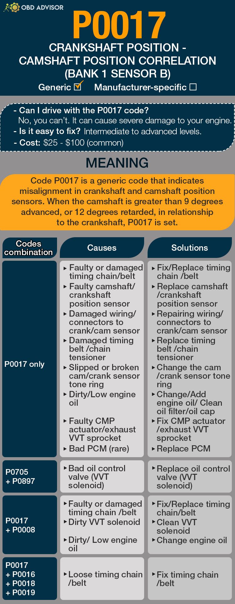
P0017 Causes Identification: Quick View
The P0017 code can occur either solely or in combinations with other related codes.
Refer to the table below to identify the root causes and solutions of P0017 and its related codes.
| Codes combination | Causes | Solutions |
|---|---|---|
| P0017 only | Faulty or damaged timing chain/belt Faulty camshaft/crankshaft position sensor Damaged wiring/connectors to crank/cam sensor Damaged timing belt/chain tensioner Slipped or broken cam/crank sensor tone ring Dirty/Low engine oil Faulty CMP actuator/exhaust VVT sprocket Bad PCM (rare) | Fix/Replace timing chain/belt Replace camshaft/crankshaft position sensor Repairing wiring/connectors to crank/cam sensor Replace timing belt/chain tensioner Change the cam/crank sensor tone ring Change/Add engine oil/Clean oil filter/oil cap Fix CMP actuator/exhaust VVT sprocket Replace PCM |
| P0017 + P0016 | Bad oil control valve (VVT solenoid) | Replace oil control valve (VVT solenoid) |
| P0017 + P0008 | Faulty or damaged timing chain/belt Dirty VVT solenoid Dirty/Low engine oil | Fix/Replace timing chain/belt Clean VVT solenoid Change engine oil |
| P0017 + P0014 | Dirty/Low engine oil Faulty camshaft position sensor Bad oil control valve (VVT solenoid) | Change engine oil Replace camshaft position sensor Replace oil control valve (VVT solenoid) |
| P0017 + P0016 + P0018 + P0019 | Loose timing chain/belt | Fix timing chain/belt |
Note: The causes for each code combination are the most common ones. There can be some uncommon issues hidden under those codes
P0017: Causes, Symptoms, And How To Fix
Regardless of the causes, the common symptoms of P0017 include:
- Check engine light on.
- Increased fuel consumption.
- Reduced engine performance.
- Engine noise and misfires (severe condition).
- Rough accelerations.
- Hard start engine problems.
Read further to identify the causes (from the most to least common) of P0017 with their relevant repairs.
Causes #1: Faulty or damaged timing chain /belt
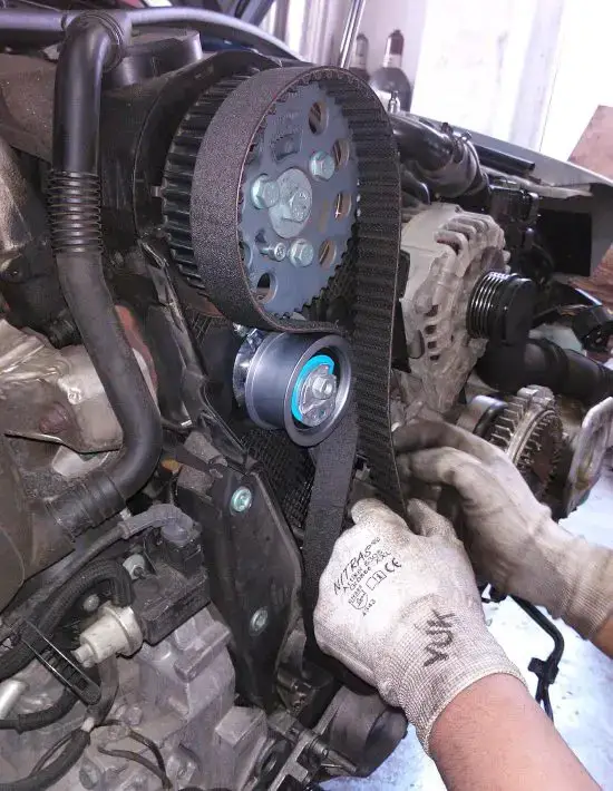
The most common cause of the P0017 code is a faulty timing chain/belt.
In this situation, the timing chain/belt affects the engine timing, causing the P0017 code to pop up.
Other related codes may sometimes show, including P0016, P0018, and P0019.
In this case, replacing the defective timing chain/belt is the best option.
You can check this video about how to change the car timing belt from the Scotty.
Causes #2: Faulty camshaft/crankshaft position sensor
Damage in the camshaft/crankshaft sensor is another possible cause of the P0017 code.
The unique symptoms you’re likely to notice in this particular cause include:
- Inconsistent sensor signals.
- Engine stalling.
- Car surging.
- “Limp mode” on, causing gear shifting problems.
Replacing the damaged camshaft/crankshaft position sensor solves this problem. This process requires an expensive scan tool to relearn the sensors (which I highly doubt that you have one.) Therefore, I suggest you bring your car to a mechanic to handle it.
Causes #3: Damaged wiring/connectors to crank/cam sensor
A damaged wiring/connector to the crank/cam sensor leads to a failing cam/crank sensor. In return, it causes intermittent problems, which the PCM detects, thus throwing the P0017 code. The symptoms for this cause are the same as for a faulty crank/cam sensor.
In some cases, a damaged crank/cam sensor wiring can also result in a combination of the P0017 and P0014 code errors.
So, it is worth inspecting the wiring connections and ensuring there are no damaged or burnt wires. If any, replace them, and you will see the code error disappearing.
Watch this video to know how to change the crankshaft/camshaft sensor connector
(by Kamal Akeel.)
Causes #4: Bad oil control valve (VVT solenoid)

A bad oil control valve (VVT solenoid) alters retarding and advancing of the valve timing as needed. In return, the engine develops oil flow problems which lead to the P0017 code manifesting. Also, the engine exhibits performance problems such as poor acceleration and rough running.
Nevertheless, the P0017 code error will sometimes appear in combination with P0014 or P0016.
In this case, replacing the bad oil control valve (VVT solenoid) is the best action you should take to do away with P0017.
Watch this video to learn how to diagnose the oil control valve.
Causes #5: Damaged timing belt/chain tensioner
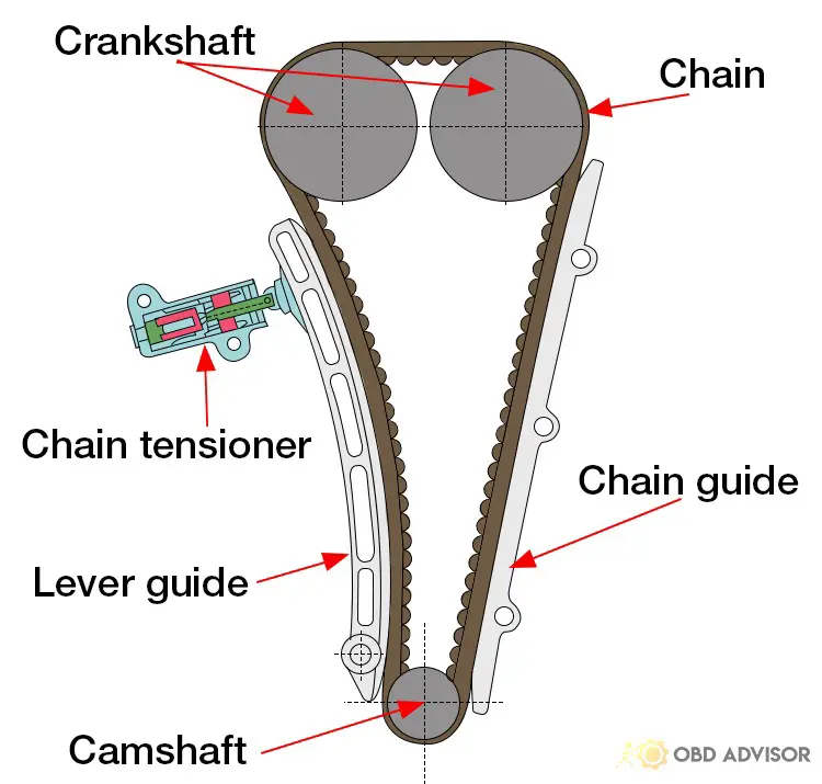
Anything going wrong with the timing belt/chain tensioner affects the timing belt. As a result, the cam and crank connection is interrupted, causing the pistons and valves to fail, thus, triggering the P0017 code. The symptoms of this issue are similar to those of a damaged timing belt/chain.
Apart from the common symptoms, the P0017 code may sometimes show in combination with the P0008 code.
The best way to solve this problem is to replace the timing belt/chain tensioner.
Causes #6: Slipped or broken cam/crank sensor tone ring
Slipped or broken cam/crank sensor tone ring interrupts the magnetic sensor from taking correct readings. As a result, the ECU indicates an inaccurate crank/cam position, thus triggering the P0017 code.
In this situation, changing the cam/crank sensor tone ring is the best solution. The process is simple as you can do it without special tools. However, you can call for mechanic assistance if you’re uncomfortable doing it yourself.
Causes #7: Dirty/ Low engine oil
The debris in an engine oil clogs the cam/crank, thus turning off the engine timing. Also, a low-quality engine oil fails to lubricate the engine parts properly. As a result, engine overheating occurs as well as breaking the rods which also turns off the engine timing.
Besides triggering the P0017 code, it can as well cause a combination of the P0017 with P0008 or P0014 codes.
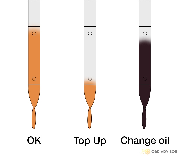
If this is the case, pouring down the engine oil and replacing it with a pure one is advisable. Also, you should develop a schedule in which you will be changing the engine oil without letting it overstay.
Before changing or adding the oil, it is advisable to clean the oil filter/oil cap. And if the oil filter/oil cap goes wrong, change it.
Watch video: How to change oil by yourself for any car in just 5 minutes by 1A Auto.
Causes #8: Faulty CMP/VVT actuator/exhaust VVT sprocket
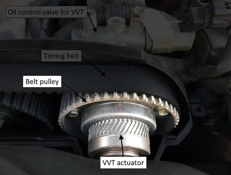
but the best option is to replace it.
Causes #9: Bad PCM (rare)
If you still see the P0017 code after solving all other causes, then check the PCM. Remember, the PCM is the main engine computer that ensures everything happening in the engine is perfect.
So, a bad PCM can trigger various trouble codes, although it rarely occurs. It can cause the P0017 code to pop up only or together with P0016.
If PCM is the problem, you should visit a mechanic shop for a replacement.
How Much Does It Cost To Fix The Code P0017?
You can fix most causes of the P0017 code by yourself with a few bucks. For instance, a new cam/crank position sensor can cost about $25-$100.
If you don’t feel comfortable replacing the parts, then a qualified mechanic comes in handy. The cost of hiring the mechanic can vary based on personal rates, but you can expect to pay between $95 and $200.
The Estimated Repair Cost Of P0017
| Solutions | Cost |
|---|---|
| Replacing the faulty timing chain / belt | DIY: $20 – $150 Mechanic: $95 – $200 |
| Replacing faulty or damaged camshaft / crankshaft position sensor | DIY: $20 -$100 Mechanic: $95 – $200 |
| Replacing damaged wiring / connectors to crank / cam sensor | DIY: $15 – $50 Mechanic: $100 – $250 |
| Replacing bad oil control valve (VVT solenoid) | DIY: $20 – $150 Mechanic: $210 – $250 |
| Replacing damaged timing belt / chain tensioner | DIY: $20 – $200 Mechanic: $500 – $2000 |
| Replacing slipped or broken cam / crank sensor tone ring | DIY: $20 – $100 Mechanic: $95 – $200 |
| Changing dirty / Add engine oil | DIY: $20 – $70 Mechanic: $40 – $120 |
| Replacing faulty CMP actuator / exhaust VVT sprocket | DIY: Not recommended Mechanic: $450 – $1630 |
| Replacing bad PCM | DIY: Not recommended Mechanic: $1000 – $3000 |
Note: The data provided in this table is dated June 2022. The exact cost of each solution can vary depending on various factors such as mechanic rates, vehicle models, etc.
You Ask, I Answer
I hope this article helps you understand why you see the P0017 code error. If so, now you can identify the causes of the code and find a quick solution that saves you time and money.
However, if you still have any disturbing questions about the P0017 code, don’t hesitate to comment in the comment box. For sure, I will respond as soon as I see it.
Similarly, you can comment and share your story if you had the P0017 code before. That way, you educate others who can apply your trick and solve these trouble codes.
See ya!
Read more: The 9 Best OBD2 Scanners for 2024: The Only Review You Need
P112F BMW Explained: Symptoms, Causes, and Solutions
P112F BMW Explained: Symptoms, Causes, and Solutions
When it comes to diagnosing and resolving issues with BMW vehicles, one troublesome code that frequently arises is P112F. This fault code pertains to the “Manifold Absolute Pressure To Throttle Angle Too High Bank 1“. Understanding its symptoms, potential causes, and possible solutions is crucial for effective troubleshooting.
Let’s dive into the details and equip ourselves with the knowledge needed to address the P112F code in BMW vehicles.
P112F BMW: A Quick Overview
Look at the summary for the BMW P112F code below!
- Definition: Manifold Absolute Pressure To Throttle Angle Too High Bank 1
- Severity: Medium
- DIY Skill Level: Intermediate
- Continue To Drive?: No
- Estimated Repair Cost: $50 – $500
What Does The P112F BMW Code Mean?
The P112F BMW is a diagnostic trouble code (DTC) that indicates a problem with the manifold absolute pressure (MAP) sensor. The MAP sensor is used to monitor engine load by sampling the depression in the inlet manifold. When the throttle valve is opened, the inlet manifold pressure decreases. The MAP sensor sends a signal to the Digital Motor Electronics (DME), which uses this signal to calculate the amount of fuel to inject into the engine.
When the P112F code gets triggered in a BMW, it signifies an inconsistency between the indicated intake manifold pressure and the calculated mass airflow, a value derived from the throttle-valve angle. In simpler terms, there is a discrepancy between the expected engine load and the actual measured values.
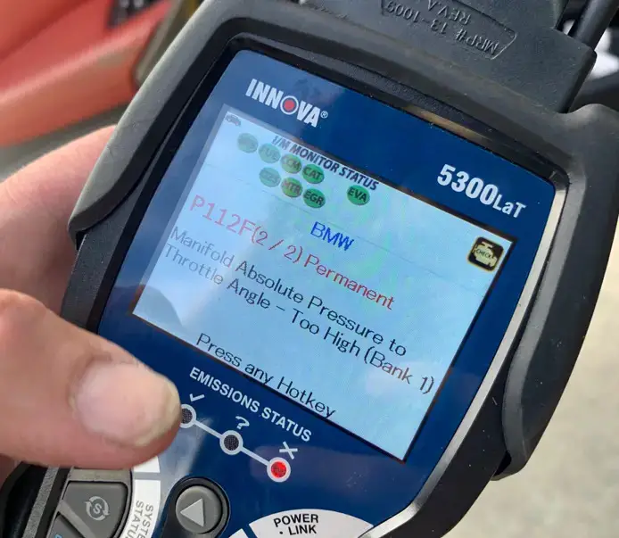
(Credit: f30.bimmerpost.com)
Here are some of the BMW models (but not limited to) usually have the P112F code: 3 Series (E90, E92, E93), 5 Series (F10, F11, N55), 7 Series (F01, F02), X3 (E83, F25), X5 (E70, F15), X6 (E71, F16).
There are a few accompanying codes that can go along with the P112F code in BMWs. These codes include: 28A0, 2D2E, P0300, P0171, P0172, etc.
How Severe Is The P1449 Code In BMW?
The P112F BMW DTC is considered a moderate severity code. This means that it can cause drivability problems, but it is not likely to cause any major damage to the engine in the short term.
However, it is still not advisable to continue driving with the P112F code. Driving with this code could eventually harm the engine. If you have the P112F code in your BMW, it is best to have it diagnosed and repaired as soon as possible. The mechanic will be able to determine the cause of the code and recommend the necessary repairs.
What Are The Signs Of The P1449 BMW Code?
Several symptoms may manifest when encountering the P112F code in a BMW vehicle. Common symptoms include:
- Check Engine Light (CEL)/Malfunction Indicator Lamp (MIL) illuminated
- Reduced engine power or loss of acceleration
- Rough idle or stalling
- Poor fuel efficiency
- Engine misfires or hesitation
- Shaking or shuddering
What Causes The P1449 Code in BMW Vehicles?
The P112F code in BMW vehicles can have various underlying causes, including:
- Wiring or electrical connection problems
- Intake manifold leaks or vacuum hose issues
- Malfunctioning MAP sensor
- Faulty throttle valve or throttle position sensor
- DME requires updates or goes defective
How to Fix And Diagnose The P112F BMW Code?
In this section, we will discuss the essential tools and parts required for the fixes. I will also provide a step-by-step guide to diagnose and repair the P112F BMW code and the rough estimates for the main repair tasks involved.
Essential Tools And Parts
In order to effectively identify and clear the C1109 code in Nissan vehicle, you will require the subsequent tools and components:
- Diagnostic scanner
- Multimeter
- Wiring and connectors
- Throttle position sensor
- Manifold absolute pressure sensor
- Vacuum hoses
Step-by-Step Procedure
1. Retrieve fault codes
Connect a diagnostic scan tool to the vehicle’s OBD-II port and retrieve any additional accompanying fault codes.
2. Inspect wiring and connectors
- Inspect the wiring harness and connectors associated with the intake pipe vacuum sensor and throttle body for any signs of damage, corrosion, or loose connections.
- Repair if necessary
3. Check for vacuum leaks
- Check the fuel vapor lines for vacuum leaks.
- Look for cracked or disconnected hoses, loose fittings, or damaged connectors.
- Fix it if the problem is detected.
4. Test the MAP sensor and throttle position sensor
- Use the multimeter to test the MAP sensor and throttle position sensor.
- The sensor readings should be within the specified range.
- If the sensor readings are not within the specified range, then replace the faulty sensor.
5. Replace the intake manifold gasket
If the sensors are within the specified range, then replace the intake manifold gasket.
6. Clear the code and test drive
- After fixing the issues, use the OBD-II scanner to clear the BMW P112F code and other trouble codes.
- Then, take the car for a test drive to check if it’s working properly again.
Read more: BMW Fault Codes: FREE Comprehensive OBD1 And OBD2 Codes List
DIY Repair Level And Estimated Costs
Diagnosing and repairing code P112F BMW requires intermediate to advanced automotive repair knowledge and experience. While some steps, such as fixing the wiring issue or vacuum leak repair, can be done by DIY enthusiasts, other tasks may require professional assistance.
The estimated cost of repairs can vary depending on the specific vehicle model, labor rates, and the need for replacement parts. Here is a table listing estimated costs:
| Repair Task | Estimated Cost |
| Wiring repair or replacement | $100 to $300 |
| Vacuum leak detection and repair | $50 to $200 |
| MAP sensor replacement | $100 to $300 |
| Throttle position sensor replacement | $100 to $300 |
| Intake manifold gasket replacement | $200 to $500 |
It is important to note that these costs are approximate and may vary significantly based on various factors, including location and dealership or independent repair shop rates. If unsure or uncomfortable with the repair process, it is recommended to seek the assistance of a qualified mechanic or automotive professional.
Final Thoughts
Ready to tackle the P112F code in your BMW? Armed with the knowledge you’ve gained, you can confidently diagnose and resolve this issue. Don’t keep this valuable information to yourself – share it with fellow BMW enthusiasts who may be facing similar challenges.
If you have any questions or success stories, we’re here to listen in the comments section below. Keep your BMW running smoothly and stay tuned for more expert automotive guides. Drive with confidence!
If you’re interested in exploring the BMW code list or other car brand OBD2 code lists, check out our OBD2 code list generator.
Reference Sources
- Professional Auto Repair, What Is Engine Misfiring? Professional Auto Repair Blog
- Delphi Auto Parts, Making Sense of Your Sensors: MAP Sensor. Delphi Auto Parts Resource Center
P1101 Chevy Cruze – Intake Air Flow System Performance
P1101 Chevy Cruze – Intake Air Flow System Performance
One of the most common diagnostic trouble codes (DTC) Chevrolet Cruze users get is the P1101. The trouble code is expected because of the unreliable nature of the PCV (Positive Crankcase Ventilation) system that Chevrolet uses for most of its vehicles. This code and a few more will still reoccur even after replacing the whole PCV system.
There is a lot of misinformation on how this system works. Therefore, I’m going to go through a basic but clear overview of how the system works. Below is an outline of how the gas flows in a Gen 1 Chevy Cruze 1.4L Turbo PCV system.
The PCV system was created to help with the engine’s ventilation to have better efficiency and fuel economy from the engine. When the motor runs, some of the exhaust gas comes through the piston rings since there is no perfect seal, but most of it goes out through the car’s tailpipe.
The gas that comes through the piston ring enters the crankcase. This creates a positive pressure which has to be evacuated. The crankcase hosts an oil separator in the valve cover. The oil separator absorbs the oil vapor from the gas and redirects it back to the engine. The rest of the gas is directed through a chamber in the valve cover into the cylinder head and then enters the intake manifold, as shown.
There is one check valve at the entry of the intake manifold. This check valve is opened under vacuum with a PCV pressure control diaphragm to allow the gas in. The PCV pressure control diaphragm regulates the amount of vacuum produced by the intake manifold when the engine is under vacuum conditions on the crankcase (the ideal vacuum is 11-18 inches of water.)
The PCV pressure control diaphragm is shown below. A lot of people refer to it as the PCV valve or the PCV vacuum regulator diaphragm.
The PCV pressure control diaphragm is prone to failure. In most cases, this is the part you will have to fix to get rid of the P1101 code and similar ones depending on the problem’s length and severity.
Once the gas passes the first check valve, it flows through a corrugated hose that leads it into the second check valve at the turbo inlet, exiting it into the turbo inlet.
The P1101 code is mostly attributed to your PCV system’s condition, cleanliness, connections and wiring, the shape of the diaphragm, and sometimes the throttle body’s cleanliness. Various car parts will eventually develop carbon build-up and house deposits over a long period of use. This dirt may sometimes lead to the occurrence of the P1101 code.
The P1101 Definition
Definition: Intake Air Flow System Performance
In some other vehicles, the P1101 code is stored when the PCM detects a problem with the Mass Air Flow Sensor System (MAF). The PCM usually detects the problem when it runs its self-diagnostic test called the Key-On Engine Running (KOER) test. The problem is registered if the MAF voltage is lower or greater than the one set by the manufacturer.
What The P1101 Chevy Cruze Trouble Code means
The P1101 Chevy Cruze code is stored when the PCM detects a problem with the Intake Air Flow System’s performance. The problem is registered if the Intake Air Flow System’s performance is lower or greater than the one set by the manufacturer.
When you see this code, the issue lies within the realm of the Intake Air Flow System. This includes the PCV system, intake manifold, check valves, connectors, wiring, and any element associated with airflow along its vicinity.
Other codes that may be related to the P1101 code in Chevrolet Cruze vehicles (depending on the length and severity of the problem) are:
1. P0171 – Fuel Trim System Lean
2. P0106 – Manifold Absolute Pressure (MAP) Sensor Performance
3. P0507 – Idle Air Control – RPM higher than expected
Some Of The Symptoms Associated With The P1101 Code Are:
1. Rough idling
Due to the increased idle speed (measured in RPM – Revolutions Per Minute) of the engine. Idle speed is the rotational speed an engine runs when it is idling (the vehicle isn’t moving, but the engine is still running.) This number will vary depending on the car. In Chevy Cruze vehicles, the number ranges from 600-800 rpm depending on the engine cylinders and transmission mode.
2. Reduction in fuel economy – this will be apparent with an increase in the liters per 100km you use. The lower the number of liters stated, the better the fuel economy.
3. Engine running roughly – you will probably notice this when you start experiencing some shaking and bouncing sensation in the car, followed by odd sounds and irregular RPM.
4. Smoke from the tailpipe – smoke out of the tailpipe is associated with several causes such as oil leakage and condensation. The smoke may appear white or blue.
5. Hissing noise in the engine bay – this will imply that there may be a leak in the engine bay (punctured hose/broken connections) or a ruptured PCV pressure control diaphragm.
Causes Of The P1101 Trouble Code In Chevy Cruze Vehicles:
1. Broken or blocked PCV system hose – The blocked hose may cause the oil to be pushed up into the combustion chamber, causing the oil to burn inside the engine and out the exhaust pipe.
2. Check valves may be blocked/clogged. Pressure change in the PCV system or dirt accumulation in the check valves will prevent efficient gas flow. The result will be a low fuel economy due to the gas and oil mixture difference.
3. Air leakage before and after the Intake Air Flow System. This may be leakage along the corrugated hose connecting the turbo and the intake manifold.
4. The PCV pressure control diaphragm may have busted/ruptured. A faulty PCV pressure control diaphragm will affect the pressure difference in the PCV system resulting in a hissing sound.
5. Air filters may be blocked. Dirty air filters may prevent sensors from getting correct readings, therefore, resulting in reading errors.
How Serious Is The P1101 Code On Chevy Cruze?
The P1101 code is mostly not an indicator of a significant problem in your Chevy Cruze. However, it would cause internal problems in your engine if left unchecked for a prolonged period. Also, depending on the severity of the problem, it will result in rough driving, terrible fuel consumption, and power loss.
Moreover, the repair cost for the problem is relatively cheap at around $50 -$60 (applies when you are replacing the PCV regulator system by yourself – which is most of the time).
As a rule of thumb, always make sure you take every warning sign seriously, especially when you don’t know the problem. Early diagnosis and fixes will save you a lot of money down the road and maybe your life too.
Also, make sure to always do regular maintenance on your Chevrolet Cruze. Just because the check engine light isn’t on, it doesn’t mean that your car is running optimally.
How To Diagnose And Fix The P1101 Code Quickly On Any Chevy Cruze
Before you pop the hood and take a look inside, you will need an OBD-II scanner.
These are the step-by-step procedures you should follow:
1. Use the OBD-II scanner to detect all the trouble codes stored in the car system.
2. Remove the PCV system cosmetic cover. Start the engine and let it run while the car is idle. Place a finger on the opening of the PCV pressure control diaphragm if you notice a hissing sound from it. If the hissing sound stops, you may have found your problem. If that is the case, all you have to do is replace the entire PCV cover since the diaphragm is fixed to it. However, it is advisable to keep diagnosing more problems to see if there is a more significant underlying issue, i.e., faulty PCV check valves.
3. Turn the engine off and locate the corrugated hose connected to the PCV check valve on the intake manifold. The hose is brittle; it may break if not carefully handled. Disconnect the hose from the base. Use a torch to look inside the pathway from which the hose has been disconnected.
4. You may notice an orange or pink like a nipple at the back of the pathway. That is the check valve. If it is not visible, use cotton swabs and rubbing alcohol to clean the region. Check again. If the check valve is not visible, this may be the problem that you were looking for. A replacement part (for the entire intake manifold from a certified seller) and further analysis from a certified mechanic may be required.
5. The next step is to check the PCV hose connected to the two check valves. Without disconnecting the other side, blow air into the hose; it should blow freely. The next step is to suck air back from the hose, after which it should block the airflow. It will need to be replaced if it doesn’t do any of the above. A hissing sound will be present if the hose is leaking while the engine is running.
6. Fix the leaks, if any, and re-run the scanner test to see whether the code is still there. If you followed all of these procedures, your problem should be fixed.
7. If the replacement unit doesn’t fix the problem, you will have to test the PCM to determine if it is terrible. A lousy PCM will have to be replaced, but this would require a qualified professional’s extensive work.
Tips To Help You Avoid Getting The P1101 Code In The Future
1. Regular cleaning and maintenance. Most car troubles can be fixed by a regular cleaning habit and a short, frequent visit to the mechanic.
2. Check for vacuum leaks regularly.
Read more: P1345 Chevy: Crankshaft position- camshaft position correlation
Frequently Asked Questions
How to replace the intake manifold?
The process is simple and straight forward. Please read this article to learn how to do it.
Can I fix the P1101 trouble code by cleaning the PCV?
Sometimes, yes. Carbon build-up and depositions tend to clog pathways and restrict airflow. A regular cleaning schedule and maintenance check may help fix the problem. However, you should make sure to check for any underlying issues even if the problem disappears.
How long can I drive my Chevy Cruze with the P1101 code?
From a statistic standpoint, you would have to reach 50000 – 70000 miles before replacing any of these parts. However, this will depend on the car model, year of make, and usage.
Is fixing the problem worth it? Should I get a better car instead?
You may be tempted to get rid of your vehicle mainly because the problem is likely to occur time and time again. However, the cost of repairing the car is more economical than what you will get by selling it. The critical parts of the vehicle are quite reliable, hence, worth the keep.
Should I buy any generic replacement parts?
No. As mentioned earlier, even the most certified replacement parts will eventually fail. It is advisable to get the most reliable one of them all for a longer life span, in which case you will need the ones from General Motors themselves.
Read More: Bad MAP Sensor Symptoms and How To Troubleshoot
B1352 Ford Code: Ignition Troubles Unveiled And Resolved
You’re out and about in your Ford, enjoying the ride, when suddenly, the Check Engine Light springs to life on your dashboard. That’s when you reach for your trusty OBD scanner, revealing the culprit: the B1352 Ford code.
Don’t worry, though – in this article, we’ll decode this secret language and help you understand what the B1352 code is all about. Whether you’re a curious driver or a DIY enthusiast, get ready to unravel the mystery behind your car’s messages and learn how to tackle the B1352 code.
B1352 Ford: A Quick Overview
Below is a summary of the B1352 Ford Code. Check it out!
- Definition: Ignition Key-In Circuit Failure
- Severity: Low
- DIY Skill Level: Intermediate
- Continue To Drive?: Yes
- Estimated Repair Cost: $20 – $250
What Does The B1352 Code Mean On Ford?
When you see fault code B1352, it means the car’s control module (BCM) noticed a problem with the ignition key circuit. This happens when you put in the key, and one of the critical wires isn’t working as it should. You might like to know, this often affects the wires that provide power to the door chimes through the ignition switch.
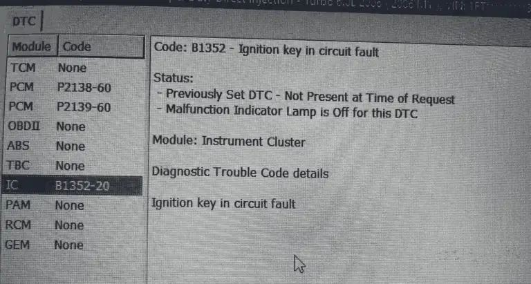
(Credit: Powerstroke.org)
Please note that the B1352 fault code is specific to certain manufacturers, appearing exclusively in Ford and Jaguar vehicles. This code doesn’t apply to all types of cars, so it’s limited to these particular brands.
Additionally, it’s essential to be aware of similar fault codes that might be recorded and could assist in identifying the issue. Codes such as B2961 and B2965 are among the codes to look for. These codes can provide further insights into the problem at hand.
How Severe Is The B1352 Ford Code?
B1352 fault code is typically a minor issue. Sometimes, the vehicle runs fine with the code, but it might also lead to a no-start condition. If the engine doesn’t crank, fixing the code quickly is best to get the vehicle running. Otherwise, addressing the problem whenever possible is a good idea to prevent potential complications.
What Are The Signs Of The B1352 Code On Ford Vehicles?
The symptoms of the B1352 Ford code may include the following:
- Check Engine Light on
- Engine cranking but not starting
- Car not starting at all
Read more: P1131 Ford: Symptoms, Causes, and How to Fix
What Causes The B1352 Ford Code?
The B1352 Ford code can be caused by the following:
- Defective door chime component
- Wiring or connection issues
- Malfunctioning ignition switch
- Bad PCM or BCM (rarely)
How To Diagnose And Fix The B1352 Ford Code
When faced with the B1352 Ford code, addressing the issue promptly is crucial for maintaining the functionality of your vehicle’s ignition system and security features. The following parts will show you essential stuff for your fixing process as well as a step-by-step guide to address the problem.
Essential Tools And Parts
- Replacement door chime component
- Wiring harness or connectors
- Ignition switch assembly
- Replacement keys (if required)
- Replacement PCM or BCM
- Obd-II scanner
- Multimeter
- Trim removal tools
- Socket and wrench set
Step-by-step Procedure
Step 1: Inspect the door chime component
Check for any signs of damage or malfunction in the door chime system. If necessary, replace the faulty component to ensure proper functionality.
Step 2: Check wiring and connections
Carefully inspect the wiring and connections related to the ignition key circuit, including those associated with the door-open switches and the ignition switch. Repair or replace any damaged wires or connectors.
Step 3: Examine the ignition switch
Inspect the ignition switch for any signs of wear, damage, or irregular operation. If the switch is problematic, consider replacing it to restore proper functionality.
Step 4: Diagnose the PCM and BCM
The PCM and BCM are integral to the vehicle’s operation and security systems. If other solutions do not resolve the issue, a comprehensive diagnostic scan of these modules may be necessary. Seek professional help to diagnose and address any potential problems with these modules.
Step 5: Clear the trouble codes
After identifying and resolving the underlying issues, it’s essential to clear the B1352 trouble code from the vehicle’s memory. This can typically be done using a diagnostic tool or by disconnecting the vehicle’s battery for a short period. Clearing the code ensures that the issue has been successfully addressed.
Read more: Complete List Of Ford OBD2 Codes for FREE Download
Estimated Costs For B1352 Code In Ford Vehicles
The cost of replacement parts for addressing the B1352 Ford code can vary based on factors such as the specific vehicle model, brand, and parts availability. If you are not confident in fixing the problem yourself, just find a skilled Ford mechanic to do it for you flawlessly.
Here’s a rough estimate of the cost for the components that might be involved in fixing the issue:
| Repair Task | Estimated Cost Range |
| Door chime component replacement | $20 to $50 |
| Ignition switch assembly replacement | $50 – $150 |
| Key replacement | $50 – $250 |
| PCM or BCM replacement/repair | $200- $1000 |
B1352 Ford Infographic
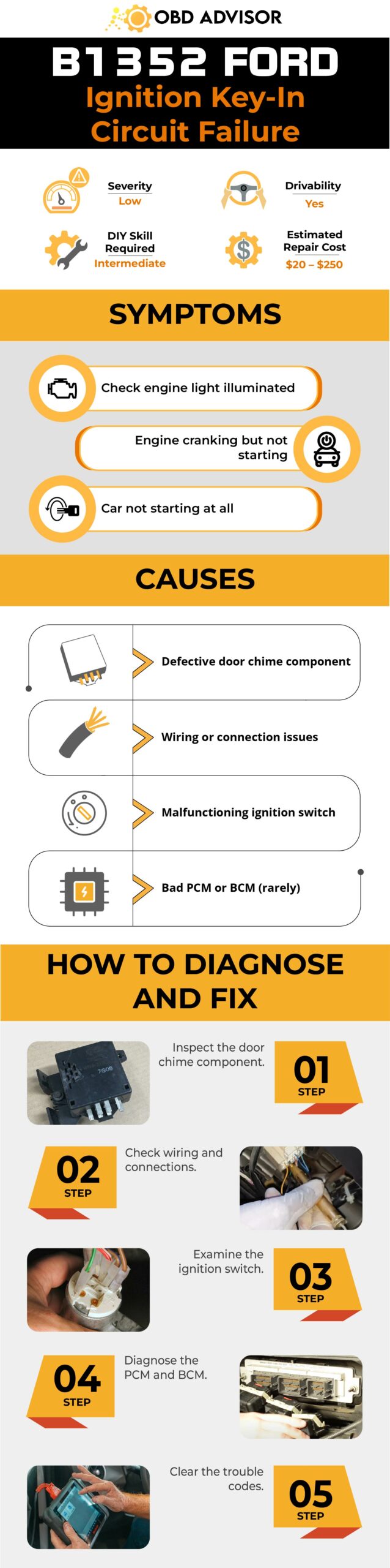
Final Thoughts
In the world of modern vehicle diagnostics, understanding and addressing specific trouble codes like the B1352 Ford code is crucial. By recognizing its significance and potential causes, you’re better equipped to navigate the path toward effective solutions.
If this article has been helpful, consider sharing it with fellow car enthusiasts. Feel free to leave your comments below, sharing your experiences or questions related to the B1352 code. Safe driving and smooth troubleshooting!
References Sources
TroubleCodes.net, B1352 OBD Trouble Code.
P1326 KIA Code: What KIA Drivers Need to Know
P1326 KIA Code: What KIA Drivers Need to Know
For KIA vehicle owners, encountering an unfamiliar error code like P1326 can be a source of confusion. Fear not, I’m going to shed light on its significance and implications.
In this article, I’ll break down what this code means, why it pops up, and what you can do about it. From understanding its potential impact on your vehicle’s performance to learning about effective solutions and preventive measures, I’ve got you covered.
Whether you’re a hands-on car enthusiast or a concerned KIA owner, we provide you with the insights needed to address the P1326 code with confidence.
Let’s dive in!
P1326 KIA: A Quick Overview
Go through the P1326 KIA code summary outlined below!
- Definition: Knock Sensor Detection System
- Severity: High
- DIY Skill Level: Advance
- Continue To Drive?: No
- Estimated Repair Cost: $100 – $400
What Does The P1326 KIA Code Mean?
The P1326 error code is associated with the Knock Sensor Detection System (KSDS) in certain Kia models. This code serves as an early warning system, detecting vibrations that indicate potential excessive wear in the connecting rod bearings of the engine.
When this code appears, the vehicle is placed in Limp Home Mode, which limits acceleration and restricts engine RPMs to approximately 1800-2000 RPM. The purpose of Limp Home Mode is to minimize further damage to the engine and prevent potential engine failure. Prompt action is crucial to address the underlying problem and avoid severe consequences.

(Credit: kia-forums.com)
The code P1326 is commonly set in many different KIA models, such as Optima, Sorento, Soul, Sportage, etc. According to Technical Service Bulletin (TSB) PI1803W/X, Kia dealers are instructed to perform specific procedures for certain models (2011-2014 Kia Optima, 2011-2013 Kia Sportage, 2012-2014 Kia Sorento) affected by the P1326 error code. Even if your Kia model is not listed or no longer under warranty, it is still recommended to take your car to a Kia dealer for a check-up and seek their advice.
How Severe Is The P1326 Code In KIA?
The P1326 error code in KIA vehicles has a high severity level. In theory, when a car experiences the P1326 error code, it may go into limp mode, where it is still technically driveable.
However, it is advisable not to continue driving your car in this state. Limp mode is a safety feature that limits the vehicle’s performance to prevent further damage. It is strongly advised to avoid driving the vehicle in limp mode and instead seek professional assistance to diagnose and address the problem promptly.
What Are The Signs Of The P1326 KIA Code?
The P1326 error code in KIA vehicles is accompanied by a range of noticeable symptoms:
- Check Engine Light (CEL) blinking
- Reduced engine power or acceleration
- Rough idling
- Engine stalling or difficulty starting
- Limp mode activated
- Knocking sound
What Causes The P1326 Code in KIA Vehicles?
Various underlying causes can trigger the P1326 error code in KIA vehicles. Some common causes for this code are:
- Faulty knock sensor
- Wiring issues
- Excessive wear in connecting rod bearings
- Engine mechanical failures (seized engine or rod knock)
- Faulty ECM (Need to update or replace)
Keep in mind that these are possible reasons, and it’s crucial to go through a detailed diagnostic procedure to pinpoint the actual issue in your specific vehicle accurately.
Read more: P1777 Nissan Code: A Practical Repair Guide
What To Do When Encountering The P1326 In Your KIA?
When encountering the P1326 error code in a KIA vehicle, it is important to take appropriate actions to address the issue effectively. In most cases, this code’s presence indicates a potential problem with the engine, which typically requires professional inspection and may involve updating or replacing the engine. Therefore, it is crucial not to drive the vehicle and immediately take it to a KIA dealer for a thorough inspection.
Attempting to clear the code yourself is not recommended, as the dealer will need to see the CEL blinking to accept addressing the issue. According to a post by Joel Strawn on Optimaforums.com, he shared his experience as follows: “I recently encountered this code and cleared it to drive home. However, when I contacted the dealer, they informed me that they would not take any action unless the MIL was flashing and the previous code was stored in the ECU. Eventually, I managed to get the light to come back on, and now they have agreed to honor the warranty for my 2016 Sorento, despite it having 113,000 miles on it. Now, I will wait and see how long it takes for the repairs to be completed.“
Why Choosing The KIA Dealer Over DIY?
It is important to understand that the faulty engine associated with the P1326 code is not something you can handle on your own. Take your car to a KIA dealer to assess if an engine update or replacement is necessary. They have the expertise and technical knowledge to diagnose the problem accurately and recommend the appropriate course of action.
KIA services are known for their excellent customer support and satisfaction. In most cases, car owners have reported receiving a new engine, albeit with additional fees for minor components or services. Therefore, it is reassuring to rely on KIA services to address the issue effectively.
If it turns out that the engine isn’t causing the issue, it might be due to problems with sensors or wiring. In this case, you’re in luck, as fixing these sensors or wiring issues usually costs around $100 to $400. This is much more affordable than having to replace the whole engine, which could cost a lot more.
Final Thoughts
So, there you have it—a glimpse of the P1326 error code in KIA vehicles. Armed with this insight, you have a better understanding of this trouble code and draw up a plan to get your KIA back on track properly.
If this article is helpful, don’t hold back—share your thoughts with fellow car enthusiasts and KIA owners. Keep the conversation going by leaving a comment below.
Here’s to smoother rides and empowered driving experiences ahead!
If you have any other codes you want to learn about, check out our OBD2 Code Lookup Tool! Get fast answers for those trouble codes. Try it now for smoother drives and peace of mind.
Reference Sources
- Technical Service Bulletin, ENGINE REPLACEMENT INSTRUCTIONS FOR DTC P1326 (PI1803W/X)
- Carotech Automotive, Can a Seized Engine Be Fixed?
- MotorTrend, What Is Rod Knock?
P1260 Ford Code: Vehicle Theft Detection?
P1260 Ford Code: Vehicle Theft Detection?
Attention, Ford owners! If you’re encountering the P1260 code on your vehicle, you’ve come to the right place.
This article provides a comprehensive overview of the P1260 Ford code. From its meaning and severity to symptoms, causes, and repair solutions, we’ve got you covered.
So, let’s get started!
P1260 Ford: A Brief Summary
Here’s a quick summary of the P1260 in Ford vehicles to provide you with essential information!
- Definition: Theft Detected, Vehicle Immobilized
- Severity: Medium
- DIY Skill Level: Intermediate
- Continue To Drive?: Yes
- Estimated Repair Cost: $100 – $500
What Is The P1260 Error In Ford Vehicles?
The P1260 code in Ford vehicles is related to the Passive Anti-Theft System (PATS). It indicates a “theft condition,” which occurs when the PATS detects either an incorrect signal or no signal at all from the chipped key. The purpose of the PATS is to prevent the unauthorized starting of the engine by immobilizing it when an incorrect key is used.
Several components are involved in triggering this code. When you insert the chipped key into the ignition, it transmits a unique code to the PATS transceiver module. This code is then sent to the instrument cluster (IC), which verifies its authenticity. If the key is determined to be valid, a signal is sent to the powertrain control module (PCM), allowing the engine to start.
However, if the IC receives an incorrect or no signal from the chipped key, the P1260 code is triggered, and the engine is disabled, preventing it from starting. It’s important to note that this code can also occur if a new instrument panel cluster (IPC), IC, or PCM is installed without proper programming, even if the vehicle is not equipped with PATS.
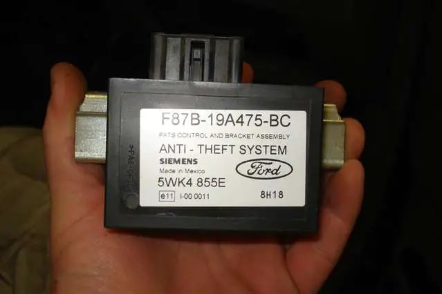
(Image credit: Explorer Forum)
The P1260 code is commonly found in various Ford models such as the F150, Mustang, Focus, Escape, Expedition, Explorer, and Fusion. If you experience a theft condition in your Ford vehicle equipped with PATS, this code may appear. It serves as an indicator to investigate the PATS system for any other related diagnostic trouble codes (DTCs) that may provide additional information about the issue.
How Serious Is The P1260 Ford Code?
The P1260 code in a Ford vehicle carries a moderate severity level. While you can still drive with this code present, it’s best to keep it to a minimum and address the issue promptly.
Sometimes the engine may engage after a short time, allowing you to continue your journey. However, there is a chance that the engine may not start at all.
So, it’s important to take action as soon as you can to restore the normal functioning of the vehicle’s anti-theft system and ensure reliable engine startup. By dealing with the code promptly, you can avoid potential inconveniences and unexpected situations on the road.
Signs Of The P1260 Ford Code
When the P1260 code is present in a Ford vehicle, it can cause several noticeable symptoms.
- Engine startup failure
- Engine immobilization
- Anti-theft light illuminated
Read more: Ford Dashboard Symbols and Meaning
Understanding Why The P1260 Ford Code Occurs
The P1260 code in Ford vehicles can be triggered by various underlying causes.
- Use of an incorrect key
- Malfunctioning key chip (transponder)
- Previous theft condition
- Issues with the wiring integrity between the transceiver and PATS module
- Malfunctioning transceiver module
- Internal concerns with the PATS or PCM module
- Incorrect programming of the PCM, IC, or IPC
Read more: Complete List Of Ford OBD2 Codes for FREE Download
Steps To Diagnose And Resolve The P1260 Ford Code
This section starts with a quick solution for the P1260 error code. Then, we’ll cover the tools, step-by-step troubleshooting, DIY repair level, and estimated costs. Let’s get started!
Quick Solution: Driving Cycle Clearing Method
Start the engine and drive the vehicle for two “driving cycles.” A driving cycle consists of starting the engine, driving the vehicle for at least 15 minutes, and then shutting it down. Repeat this process once more, completing a total of two driving cycles.
After completing the two driving cycles, start the engine for the third time. If the issue is successfully resolved, the P1260 code should clear itself.
If the quick solution does not resolve the issue, you can proceed with the following detailed steps.
Essential Tools And Parts
To diagnose and repair the P1260 code, you will need the following tools and parts:
- OBD-II scanner
- Basic hand tools: Screwdrivers, pliers, etc.
- Multimeter
- Replacement parts: Key, wiring harness, transceiver module, etc.
Your Step-by-Step Guide
- Retrieve codes using a compatible diagnostic tool. Connect the tool to the OBD-II port and access the PATS module to get the codes indicating PATS-related problems.
- Analyze retrieved codes and troubleshoot PATS issues. Review the codes obtained from the PATS module and use them to identify specific PATS-related problems. Perform necessary troubleshooting steps, such as checking wiring connections, inspecting components, or replacing faulty parts, based on the analysis of the codes.
- Ensure proper key usage. Verify the correct key and try a second key, if available, to rule out a faulty key.
- Reset the P1260 code after resolving PATS issues. Keep the key in the “on” position for about two minutes or until the theft light stops flashing. Attempt to start the vehicle and check if the system resets.
- Check the steering column shroud for tampering. Inspect for damage and ensure the transceiver module behind the shroud is securely in place.
- Look for aftermarket remote start systems. If present, have them inspected or removed by a professional, as they can interfere with the PATS system.
- Ensure proper programming if a new PCM was installed. Reprogram keys to synchronize with the new PCM if needed. Seek assistance from a locksmith or professional experienced in PATS reprogramming.
- If the issue persists, visit a dealer or shop with a compatible scanner to perform advanced diagnostics and troubleshooting on the PATS system.
DIY Repair Level And Estimated Costs
When it comes to repairing the P1260 code related to the PATS system, the level of DIY repair can vary depending on the specific cause and the individual’s expertise. It is essential to assess your own skills and comfort level with automotive repairs before attempting to fix PATS-related issues on your own. If you are unsure or have limited experience, it is recommended to seek assistance from an expert or mechanic who specializes in automotive security systems.
Here is a breakdown of estimated costs for some of the main repair tasks associated with the P1260 code and the PATS system. Please note that these costs are approximate and can vary based on factors such as location and specific vehicle requirements.
| Repair Task | Estimated Cost Range |
| Wiring Harness Repair | $30 to $200 or more |
| Key Replacement | $50 to $300 |
| PATS Module Replacement | $100 to $200 |
It’s important to consider these costs as a general guideline and be aware that actual expenses may differ. Before making any decisions, it’s advisable to research local prices and consult with professionals or authorized service centers for accurate estimates tailored to your specific situation.
P1260 Ford Infographic
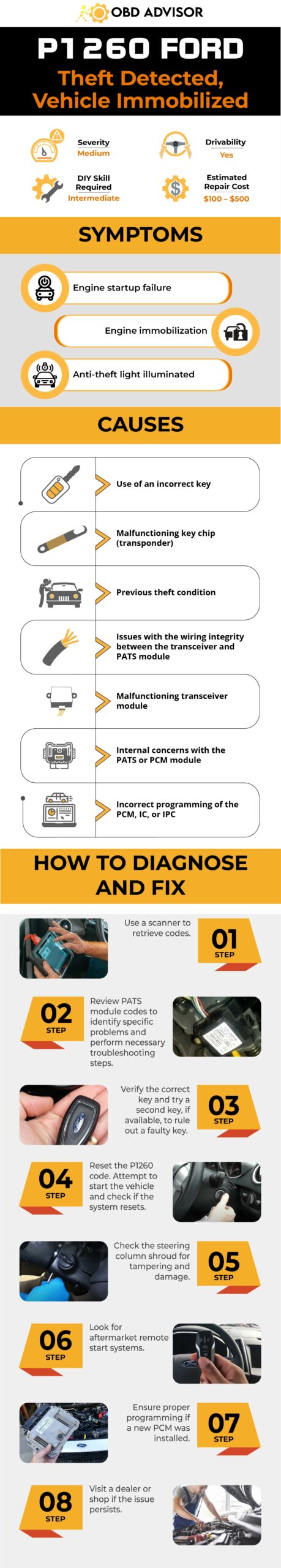
Wrapping Up
Dealing with the P1260 Ford code can be a bit tricky, but we’re here to help you out. If you follow our instructions and have the right tools and parts, you have a good chance of fixing the issue.
However, it’s important to remember that if you’re unsure or lack experience, seeking professional assistance is always a wise decision. Don’t hesitate to reach out to an expert or mechanic for accurate diagnosis and guidance.
If you found this information helpful, feel free to share it with others who may benefit, and don’t forget to leave your comments and questions below. Safe travels!
Reference Sources
- Sportsmobile Forum,How to clear P1260 error – Theft Detected – Engine Disabled.
- Trouble Codes, P1260 – Theft Detected Vehicle Immobilized.
- JustAnswer, P1260 – Theft Detected, Vehicle Immobilized – Is There a Fix?.
- Fixya, Code P1260, what does it mean and how to fix it.
- Craig D, 2021, 2012 Ford Fusion – MotoLogic.
- McGill University, 2007 PCED On Board Diagnostics – SECTION 4: Powertrain.
P1605 Toyota Code: Engine Rough Idling Solutions
P1605 Toyota Code: Engine Rough Idling Solutions
Welcome to our informative guide on P1605 Toyota, a diagnostic trouble code that can affect the performance and reliability of your Toyota vehicle.
If you’ve encountered this code, it’s important not to panic. In this article, we’ll explore P1605 Toyota in-depth, covering its meaning, severity, symptoms, causes, diagnosis, and repair steps.
As a seasoned mechanic with years of experience, I aim to share my expertise and help you navigate through this issue effectively.
So, let’s dive in and solve the P1605 Toyota together.
P1605 Toyota: A Quick Overview
Here’s a quick overview of the P1605 for Toyota. Check it out!
- Definition: Engine Rough Idling
- Severity: Medium
- DIY Skill Level: Advanced
- Continue To Drive?: No
- Estimated Repair Cost: $200 – $500
Understanding The Meaning Of P1605 Toyota – Engine Rough Idling
The P1605 diagnostic trouble code is triggered when the engine speed of a Toyota vehicle drops below the set speed. Specifically, this code is stored when, after 5 seconds or more elapse following engine startup, the engine speed decreases to 400 rpm or less, as detected by the vehicle’s onboard computer (ECM) using a one-trip detection logic.
To fully comprehend the implications of P1605 Toyota, it’s essential to understand the systems and components involved. This code is typically associated with the engine control and SFI (Sequential Fuel Injection) systems. These systems work together to regulate the engine’s performance, fuel injection timing, and various other parameters to ensure smooth operation.
When the engine speed drops below the set speed, it indicates an irregularity in the engine’s idle control or a potential malfunction within the components linked to idle stability.
Commonly affected models include the Corolla (especially years 2012 and 2015), Highlander, Tundra, Camry (especially years 2012, 2013, and 2014), RAV4, Tacoma, Vitz, Hilux, Land Cruiser, Prado, 4Runner, Belta, Yaris, and Land Cruiser.
It’s worth noting that the P1605 code is often associated with related codes, such as P1603 and P1604, which further aid in diagnosing the underlying issue.
Read more: Complete Toyota OBD1/OBD2 Codes List [FREE DOWNLOAD]
Special Note About P1605 Toyota Code
In some specific Toyota models, the P1605 code can refer to a Knock Control CPU malfunction, indicating a problem with the engine’s knock control system. However, it’s important to note that this article specifically focuses on the P1605 code pertaining to Engine Rough Idling. The information provided here is intended for diagnosing and resolving engine rough idling issues associated with the P1605 code.
If your Toyota model is affected by the Knock Control CPU malfunction, it is recommended to consult a professional mechanic or authorized Toyota service center for an accurate diagnosis and appropriate resolution, which may involve checking the Engine Control Module (ECM) for faults or malfunctions and repairing or replacing it if necessary.
How Serious Is The P1605 Toyota Code?
When it comes to the severity of the P1605 Toyota code, it is generally considered to have a moderate level of severity. While it may not pose an immediate safety risk, it is crucial not to ignore or neglect this code.
Driving with the P1605 code present can lead to various issues, including rough idling, decreased engine performance, and potential stalling. These symptoms can impact the overall drivability and reliability of your Toyota vehicle.
To ensure the longevity and optimal performance of your vehicle, it is advisable to address the P1605 code promptly. Continuing to drive without addressing the underlying cause can potentially lead to further damage to engine components or other related systems.
Read more: Toyota Dashboard Symbols and Meanings (FULL list, Free Download)
Common Symptoms Of P1605 Toyota
The P1605 Toyota code can manifest in various symptoms, indicating an issue with the engine speed or idle control. Common symptoms include:
- Check engine light illuminated
- Rough idle
- Slow acceleration
- Engine vibration leading to engine shutdown
- Engine shutdown without vibration
- Engine starts with accelerator pedal depressed
- Rough idling after engine startup
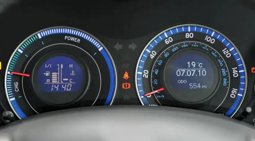
(Image credit: Toyota Owners Club Forum)
Exploring The Causes Of P1605 Toyota
The P1605 Toyota code can have various underlying causes that trigger the engine speed drop. To help you easily follow the list, the causes are categorized as follows:
| System/Component | Causes |
| Intake System | Air leak in the intake system |
| Emission Control System | Brake booster assembly |
| Purge VSV | |
| Sensor and Sensor Circuit | Power supply circuit |
| Engine coolant temperature sensor | |
| Mass air flow meter subassembly | |
| Fuel System | Fuel pump control circuit |
| Fuel pump | |
| Fuel line | |
| PCV valve and hose | |
| Engine Control System | Ignition system |
| Camshaft timing oil control valve assembly | |
| Knock control sensor | |
| Other Systems and Components | Wire harness or connector |
| Thermostat | |
| Park/Neutral Position switch assembly | |
| Air Conditioning system | |
| Electrical load signal system | |
| Power Steering system | |
| Charging system | |
| Automatic Transaxle system | |
| Immobilizer system | |
| ECM |
How To Accurately Diagnose And Repair P1605 Toyota Code?
In this section, we will cover the essential tools and parts required, provide a step-by-step procedure for diagnosing and fixing the code, and discuss the DIY repair level and estimated costs.
Diagnostic Tools And Essential Parts
To diagnose and repair the P1605 Toyota code, you may need the following tools and parts:
- Diagnostic scanner
- Multimeter
- Vacuum gauge
- Smoke machine
- Intake gaskets
- Sensor replacement parts
- Ignition components
- Fuel system components
Step-by-Step Guide
Diagnosing and fixing the P1605 Toyota code involves two cases based on the engine speed decrease. Follow the steps below for each case:
Case 1: Engine Speed Decreased Slowly
Step 1: Inspect ignition system
Inspect the ignition system components, including spark plugs, power supply circuit, and ignition coil assembly. Look for any faults or malfunctions. Repair or replace if required.
Step 2: Perform air fuel ratio check
- Inspect the intake system for air leaks. Check the connections and brake booster assembly. Repair any leaks found.
- Test the air-fuel ratio related sensors, such as the mass air flow meter, air-fuel ratio sensor, thermostat sensor, and engine coolant temperature sensor. Repair or replace any malfunctioning sensors indicating richness or leanness beyond normal limits.
- Verify the fuel supply system, including the fuel pump control circuit, purge VSV system, fuel lines, and ECM. Repair or replace any damaged components.
If the vehicle still exhibits abnormal behavior, proceed to the next steps.
Step 3: Check intake air volume
- Check the intake air volume to ensure it is sufficient. Inspect the air passage for obstructions and excessive valve overlap in the camshaft timing oil control valve assembly. Repair or replace faulty components if necessary.
- Clean the intake manifold and throttle body if required.
- Check the vacuum system for leaks and repair any detected issues.
Step 4: Verify ignition timing
Verify that the ignition timing is operating properly. Adjust it if necessary to ensure correct timing.
Case 2: Engine Speed Decreased Rapidly
Step 1: Check electrical system
- Inspect the ignition and injection system for any electrical system malfunctions.
- Look for signs of power interruption or temporary power cuts.
- Examine the power supply circuit to the fuel injector and ignition coil assemblies.
- Repair or replace any faulty components in the electrical system.
Step 2: Verify external load
- Examine external components that may be causing an increased load on the engine, such as the power steering or air conditioning system.
- Note any malfunctions or abnormalities in these external parts.
Step 3: Address external part malfunctions
If any external part malfunctions are identified, repair or replace the faulty components. Ensure proper functioning of external systems that can impact engine load.
DIY Repair Level And Estimated Costs
The repair procedure for the P1605 Toyota code is classified as advanced. It involves checking and inspecting multiple components within the engine system, requiring a good understanding of engine systems, diagnostic tools, and troubleshooting techniques.
If you are unsure or uncomfortable with the procedure, it is highly recommended to seek assistance from an experienced mechanic or automotive professional who can accurately diagnose and resolve the issue.
Estimated costs for main repair tasks are as follows:
| Repair Task | Estimated Cost |
| Wiring repairs | $50 – $150 |
| Vacuum system leak repair | $50 – $150 |
| Air-fuel ratio sensor replacement | $50 – $200 |
| Mass air flow meter replacement | $100 – $300 |
| Thermostat sensor replacement | $50 – $150 |
| Engine coolant temperature sensor replacement | $50 – $150 |
| Ignition component replacement | $100 – $300 |
| Fuel system component replacement | $100 – $500 |
Remember, these are estimated costs and can vary based on various factors such as location, vehicle model, and labor rates. It is advisable to consult with a professional for accurate cost estimates.
P1605 Toyota Infographic
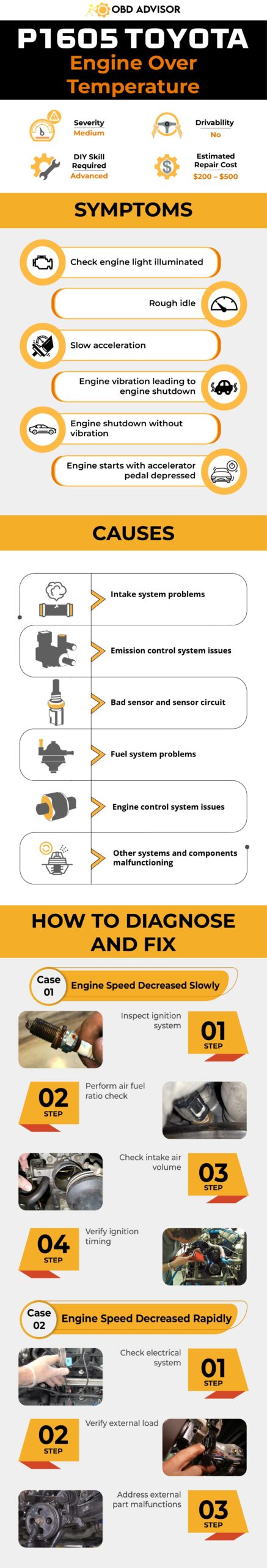
Wrapping Up
Before we wrap up our discussion on the P1605 Toyota code, let’s take a moment to applaud your commitment to understanding, diagnosing, and fixing the issue. It’s no easy task, but with the right tools, knowledge, and a dash of persistence, you’re well on your way to getting your Toyota back in top shape.
Remember to approach the process step-by-step, examining the air-fuel ratio, intake system, sensors, ignition components, and fuel system. If you ever feel stuck or unsure, don’t hesitate to ask a trusted mechanic for help.
Keep up the great work, and we’re here to support you every step of the way! Share your thoughts or questions below – we’d love to hear from you.
Reference Sources
MotoLogic, 2014 Toyota RAV4 P1603, P1605 Repair Manual
P1614 Nissan Code: Causes And Solutions Of NATS Issues
P1614 Nissan Code: Causes And Solutions Of NATS Issues
Hello, fellow Nissan enthusiasts! Are you stumped by the P1614 code?
It can be a real head-scratcher but don’t worry – as an experienced mechanic and lover of all things Nissan, I’m here to help.
In this blog post, we’ll take a closer look at the P1614 Nissan code and what it means for your vehicle. We’ll cover everything from the symptoms to the solutions, so grab a cup of coffee and let’s dive in!
P1614 Nissan: A Quick Overview
Below is a summary of the P1614 Nissan code. Check it out!
- Definition: Chain of IMMU-KEY
- Severity: Medium
- DIY Skill Level: Intermediate
- Continue To Drive?: No
- Estimated Repair Cost: $100 – $500
What Does The P1614 Code Mean On Nissan?
The P1614 trouble code on Nissan vehicles is a signal of a communication issue between the key and the engine immobilizer in the Nissan Anti-Theft System (NATS). Specifically, this code indicates a chain of IMMU-KEY errors, as explained by Nissan in a technical document used for advanced diagnostics that “IMMU cannot receive key ID & Dongle unit is malfunctioning (IF FITTED).“
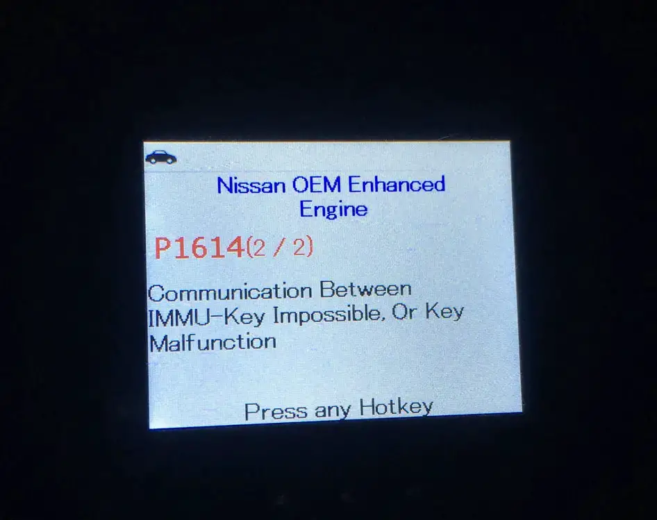
The NATS or Nissan Vehicle Immobilizer System (NVIS) is an integrated anti-theft system designed to prevent the unauthorized starting of the engine. This system works through the cooperation between the key, engine control module (ECM), and immobilizer control unit (IMMU). The IMMU is responsible for validating the key and sending a signal to the ECM to allow the engine to start. If the IMMU detects an issue with the key or the signal, it will set the P1614 code. Other codes related to the Nissan anti-theft system, such as P1610 (Lock Mode), P1615 (Difference of Key), and P1612 (Chain of ECM-IMMU), can also be triggered alongside the P1614 code.
Is the P1614 Nissan Code Serious?
The P1614 code in Nissan vehicles is a moderately severe issue that should be addressed as soon as possible. While it may not have immediate consequences, neglecting the issue could lead to potential problems down the line.
Regarding driving with the P1614 code, it is not recommended. This is because the code is often related to the vehicle’s immobilizer system, which could prevent the car from starting or operating properly. Attempting to drive the vehicle with this code active could cause further damage, resulting in costly repairs.
What Are The Warning Signs of the P1614 Nissan Code?
Here are some warning signs that you may encounter if the P1614 code is triggered:
- Car starting issues such as engine cranking but not starting, engine starting, and then stalling. This is because the immobilizer system is preventing the engine from starting without a properly registered key.
- Immobilizer warning lights
- Illuminated check engine light
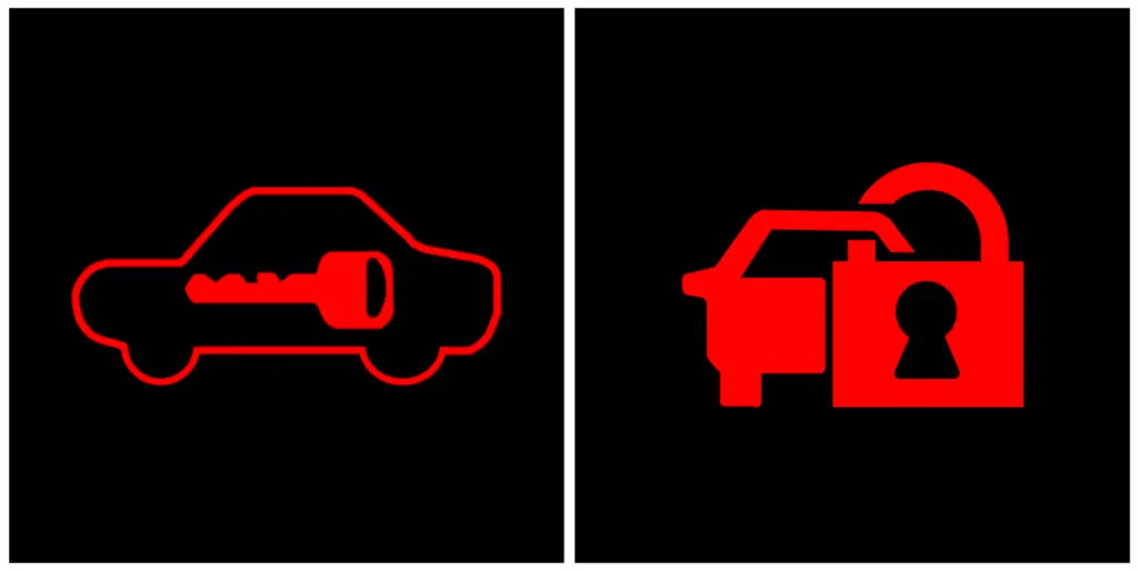
What Causes the P1614 Nissan Code?
There are several possible causes of the P1614 code on Nissan vehicles:
- Damaged, not programmed, improperly registered NATS ignition key
- Dead or low battery in the key fob
- Failed NATS (especially NATS antenna)
- Faulty IMMU or BCM
- Faulty ECM (in rare cases)
How To Diagnose and Fix The P1614 Nissan Code?
If your Nissan is displaying the P1614 code, it’s crucial to address the issue promptly to ensure the proper functioning of your vehicle’s immobilizer system. Fortunately, there are several steps you can take to diagnose and fix the problem, as below. Let’s explore!
Tip: If you see the P1614 error code along with the P1610 code, it’s important to escape from the lock mode. So how to do it? First, turn the key to the “ON” position and wait for the security light to turn off. Then, turn the key to the “OFF” position. Next, repeat this process for a total of three cycles.
Essential Tools and Parts
- Diagnostic scanner
- Car key programmer
- Nissan key fob battery
- Key fob transponder chip
- NATS antenna
Step-by-step Procedure
Step 1: Use a diagnostic scanner to retrieve any trouble codes that may be present. This can help identify any related issues that may be contributing to the P1614 code.
Step 2: Check that you are using the correct key for your Nissan. Make sure it is not damaged or worn out. Sometimes you might find a damaged transponder chip inside the key. If you have a spare key, try using it to determine if the error code still appears.
Note: I always recommend testing the key using a car key programmer/tester to be sure. Sometimes, I’ve found that a faulty ignition switch coil can cause the engine not to start and trigger the P1614 code. In these cases, the key test tool may detect the issue. If the ignition switch coil is found to be faulty, I replace it and test again to see if the problem is resolved.
Step 3: Check the condition of the key fob’s battery. If it’s weak or dead, communication issues between the key and the IMMU might occur. Replace the battery if necessary.
Step 4: Reset the immobilizer system by disconnecting the battery for several minutes, then reconnecting it.
Step 5: Inspect the NATS antenna operation. Replace it if necessary by following the steps in the service manual.
Step 6: If the above steps do not resolve the issue, reprogramming the key to the vehicle’s IMMU system may be necessary. To ensure proper reprogramming, it’s best to seek the help of a qualified automotive locksmith or a Nissan dealership as they have the necessary expertise and equipment.
Step 7: If the issue still persists, there may be a problem with the IMMU system itself. As dealing with this system is a complex task, it is advisable to leave it to your nearest Nissan dealership or a certified mechanic with experience in Nissan vehicles. If the issue is determined to be with the BCM, it may need to be reprogrammed.
Estimated Repair Costs for P1614 Code in Nissan Vehicles
While DIYers can do some of the steps outlined above with some automotive experience, it’s important to recognize when a repair is beyond your skill level and seek assistance from a qualified professional. In particular, tasks such as replacing the NATS antenna or reprogramming the key or BCM require specialized equipment and knowledge and can be costly if done incorrectly.
The estimated repair costs for these steps can vary widely, as shown in the table below. It’s important to be prepared for some variation in repair costs, depending on the specific task and where you have it done.
| Repair Task | Estimated Cost |
| Key fob battery replacement | $5-$20 |
| NATS antenna replacement | $200-$500 |
| Key reprogramming | $50-$150 |
| BCM reprogramming | $200-$500 |
P1614 Nissan Infographic
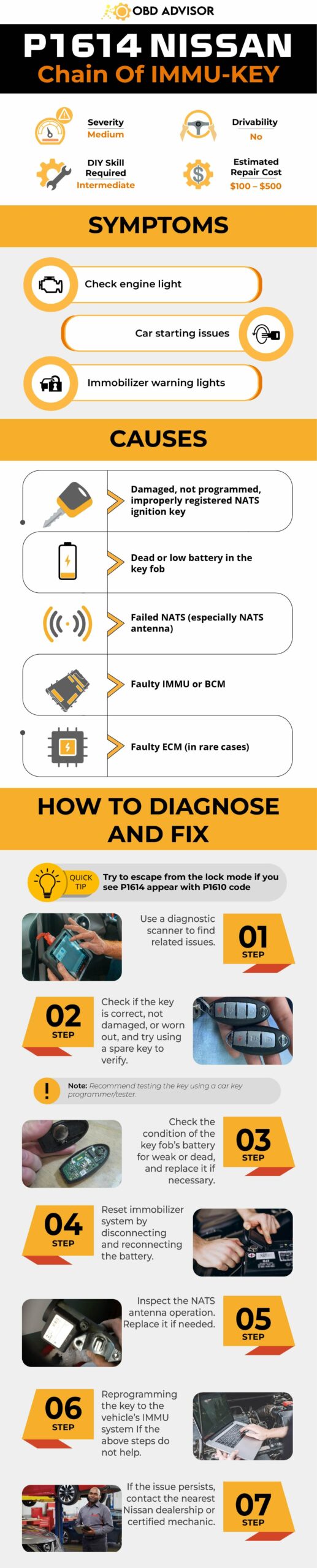
Final Thoughts
We hope this article has provided valuable insights into the P1614 Nissan code. Remember, working with the immobilizer system can be complex. Therefore, if you’re not confident in automotive repairs, it’s always best to seek assistance from a professional to avoid causing further damage. Additionally, always follow the manufacturer’s instructions and safety protocols when working on your vehicle.
If you have any questions or comments, feel free to leave them below. And if you found this article helpful, please share it with your fellow Nissan enthusiasts. Safe driving!
References Sources
- Nissan Manual for Advanced Diagnostics
- Nissan North America (2005), Technical Service Bulletin: Campaign – ECM reprogramming for engine misfire diagnostic trouble codes (DTC P0300-P0306).
P0016: Crankshaft Position – Camshaft Position Correlation (Bank 1 Sensor A)
P0016: Crankshaft Position – Camshaft Position Correlation (Bank 1 Sensor A)
Your check engine light turns on, throwing the P0016 code? Well, that’s an alert, signaling troubles in your car engine timing. But, what next?
Let’s take a brief look at the information below.
- P0016 Definition: Crankshaft Position – Camshaft Position Correlation (Bank 1 Sensor A).
- Code Type: Generic – P0016 indicates the same problem whether you’re having a Chevy, Dodge, or Ford, etc.
- Can I drive with the P0016 code? No, keeping driving can cause more damage to the engine.
- Easy to fix? DIY to advanced levels.
- Cost: $30 – $150 (common)
Due to its severity, most people get confused and frightened when they see the P0016 code. Stay calm, I will tackle this error code in-depth, including its causes, diagnosis, symptoms, and quick solutions in this article.
Let’s dive in for more details!
What Does The P0016 Code Mean?
P0016 code stands for Crankshaft Position – Camshaft Position Correlation (Bank 1 Sensor A). This indicates that the engine timing is having problems resulting from the misalignment in the crankshaft and camshaft positions.
- Bank 1: Means that the problem is on the engine side containing cylinder 1.
- Sensor A: Indicates that the issue is affecting the intake camshaft side.
Crankshaft Vs. Camshaft
The crankshaft and camshaft are connected with a timing chain located at the end of the engine.
- Camshaft: control the valves, which allow the air-fuel mixture to enter the combustion chamber and release the burnt exhaust gas.
- Crankshaft: Harness the engine’s torque to rotate the camshaft.
These two shafts must have perfect timing for optimum control of the combustion. If the correlation is off, it leads to power loss, engine overheating, misfire, etc.
Engine Timing
To prevent the correlation from going off, the engine timing must be controlled with the help of various parts:
- Timing belt/chain.
- VVT sprocket.
- Timing belt tensioner.
- Oil control valves.
- Camshafts and crankshafts solenoid.
- Camshafts and crankshafts.
In case any of the above parts goes wrong, it leads to the P0016 code popping up.
Other related trouble codes of P0016 include P0017, P0008, P0014, P0009, and P0019.
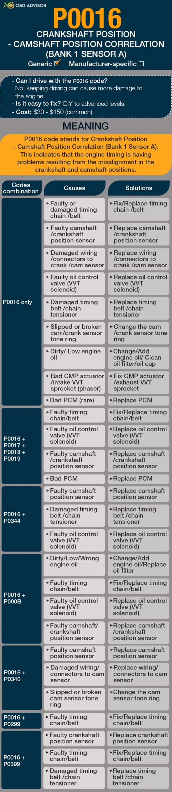
P0016 Causes Identification: Quick View
There are various causes of the P0016 DTC. Usually, a faulty camshaft/crankshaft position sensor is the main one.
In most cases, you may see the P0016 only, but sometimes, it may occur in combination with other related codes. Check the table below to understand those specific combinations and their specific causes.
| Codes Combination | Causes | Solutions |
|---|---|---|
| P0016 only | Faulty or damaged timing chain /belt Faulty camshaft/crankshaft position sensor Damaged wiring/ connectors to crank /cam sensor Faulty oil control valve (VVT solenoid) Damaged timing belt /chain tensioner Slipped or broken cam/crank sensor tone ring Dirty/ Low engine oil Bad CMP actuator/intake VVT sprocket (phaser) Bad PCM (rare) | Fix/Replace timing chain /belt Replace camshaft/crankshaft position sensor Replace wiring/ connectors to crank /cam sensor Replace oil control valve (VVT solenoid) Replace timing belt /chain tensioner Change the cam/crank sensor tone ring Change/Add engine oil/ Clean oil filter/oil cap Fix CMP actuator/exhaust VVT sprocket Replace PCM |
| P0016 + P0017 + P0018 + P0019 | Faulty timing chain/belt Faulty oil control valve (VVT solenoid) Faulty camshaft/crankshaft position sensor Bad PCM | Fix/Replace timing chain/belt Replace oil control valve (VVT solenoid) Replace camshaft/crankshaft position sensor Replace PCM |
| P0016 + P0344 | Faulty camshaft position sensor Damaged timing belt /chain tensioner Faulty oil control valve (VVT solenoid) | Replace camshaft position sensor Replace timing belt /chain tensioner Replace oil control valve (VVT solenoid) |
| P0016 + P000B | Dirty/Low/Wrong engine oil Faulty timing chain/belt Faulty oil control valve (VVT solenoid) Faulty camshaft/crankshaft position sensor | Change/Add engine oil/Replace oil filter Fix/Replace timing chain/belt Replace oil control valve (VVT solenoid) Replace camshaft/crankshaft position sensor |
| P0016 + P0340 | Faulty camshaft position sensor Damaged wiring/ connectors to cam sensor Slipped or broken cam sensor tone ring | Replace camshaft position sensor Replace wiring/ connectors to cam sensor Change the cam sensor tone ring |
| P0016 + P0299 | Faulty timing chain/belt | Fix/Replace timing chain/belt |
| P0016 + P0399 | Faulty crankshaft position sensor Faulty timing chain/belt Damaged timing belt /chain tensioner | Replace crankshaft position sensor Fix/Replace timing chain/belt Replace timing belt /chain tensioner |
P0016: Causes, Symptoms, And How To Fix
Although the causes of P0016 may show varying symptoms, here are the most common ones that you should look out for.
- Check engine light on
- Poor car engine performance
- High fuel consumption
- Engine hard start
- Rattling sounds from the engine
The onset of these signs needs quick action. So, keep reading to learn more about the causes and what to do if you encounter one.
Cause #1: Faulty Timing Chain/Belt
The timing belt/chain helps in synchronizing the crankshaft and the camshaft timing.
For some reason, the timing chain/belt may skip a few teeth, putting the cam and crank out of sync.
Faulty timing chain/belt symptoms:
- Loss of power when the car is cruising (Timing chain/belt skipped one tooth).
- Knocking sounds from the engine (Timing chain/belt skipped two teeth).
- Can’t start, no pressure when doing a compression test (Timing chain/belt skipped three teeth).
- P0016 may appear alone or come along with P0299, P0399, P000B, P0017, P0018, or P0019.
If this is your case, replacing the faulty timing chain/belt will solve the problem. Having that job done is not complex because no special mechanic experience is needed.
Cause #2: Faulty Camshaft/Crankshaft Position Sensor
The camshaft/crankshaft position sensors are responsible for monitoring the cam and crank position.
When one of these sensors get faulty, it conveys inaccurate data, leading to mismatched ignition timing and fuel delivery. The PCM sets up the P0016 code to signal this problem.
Faulty camshaft/crankshaft position sensor symptoms:
- Engine vibrations and misfire
- Gear shifting problems
- Engine stalling
- Rough idling
To solve this problem, you need to replace the camshaft/crankshaft position sensor. Bear in mind that you should choose the OEM parts for the best result.
Cause #3: Damaged Wiring/Connectors To Crank/Cam Sensor
The wiring/connector linking to the crank/cam sensor can be burnt, unplugged, or shorted. As a result, the functions of the sensor and other engine timing parts are compromised, triggering P0016. Note that the DTC may appear as P0016 only or as P0016+P0344.
Damaged wiring/connectors to crank/cam sensor symptoms:
- Ignition problems
- Poor idling
- Failure in tachometer
- Engine misfiring
If the wires are unplugged, locate and plug them in to fix the issue. However, you should replace the wiring/connectors to the crank/cam sensor if they are shorted, burnt or their insulation is damaged.
Cause #4: Faulty Oil Control Valve (VVT Solenoid)
Oil control valve’s function is to alter the camshaft rotation, giving the engine better performance at different RPMs. This component is only available if your engine has the variable valve technology (VVT.)
If a faulty oil control valve is the culprit, either the car has poor gas mileage at low RPM or lack of power at WOT.
Besides, the P0016 may show alone or in combination with P000B, P0017, P0018, P0019, or P0344.
Replacing the oil control valve (VVT solenoid) should fix the problem. This process is not difficult and you can do that right in your garage.
Cause #5: Damaged Timing Belt/Chain Tensioner
Over time, the timing belt/chain material wears out and gets overstretched, causing it to fail.
For that reason, a timing chain/belt tensioner is used to keep the timing belt/chain more tightened.

If the timing chain/belt tensioner gets damaged, the timing chain/belt becomes loose. This will cause engine timing problems, which the PCM will detect and set up P0016 to send signals of the issue.
Similarly, this cause can trigger a combination of the P0016 code with P0399 or P0344.
In this case, you need to replace the timing belt/chain tensioner.
Cause #6: Slipped Or Broken Cam/Crank Sensor Tone Ring
Due to the crank rotation impact, the sensor tone ring may get loosened, damaged, or fail to shear the key aligning them. Sometimes, the DTC can occur as P0016 only or as P0016 + P0340.
If your cam/crank sensor tone ring is the culprit, replacing it is the best option to go for eradiating the code.
Cause #7: Dirty/Low/Wrong Engine Oil
Dirty engine oil is a common cause of faulty oil control valves. This happens when the debris builds up, thus blocking the valves.
Similarly, low/wrong engine oil can also affect the engine timing. If the oil has a wrong viscosity, the camshaft phaser fails to work right.
Either way, dirty/low/wrong engine oil affects the engine timing badly, which triggers the P0016 and sometimes P0016+P000B.
If this happens, flush the engine oil and ensure that you use compatible engine oil to avoid the same mistake.
Cause #8: Bad CMP Actuator/Exhaust VVT Sprocket
Most vehicles use the CMP actuators/exhaust VVT sprocket to change the cam position and advance or retard the valve timing. If it goes bad, it will cause the crankshaft and camshaft to misalign.
Since the PCM controls the VVT solenoids that apply oil pressure on the actuator, it will detect the change and set up the P0016 code. In this case, a replacement of the CMP actuator/exhaust VVT sprocket is needed to solve the P0016 code error.
Cause #9: Bad PCM (Rare)
Once every possible cause of P0016 DTC is checked out, a bad PCM remains the only culprit. Similarly, this issue can trigger a combination of P0016 with P0017, P0018, and P0019.
The problem occurs once the PCM fails to control the engine ignition and spark, though it is rare. However, if it happens, the PCM is a complicated part that requires you to have a qualified mechanic to fix it. The mechanic can decide either to reprogram the PCM or replace it, depending on the severity of the problem.
How Much Does It Cost To Fix The Code P0016?
The cost of fixing the P0016 code depends on whether you are doing it yourself or using mechanic services. DIY will cost you a few dollars. For example, replacing a camshaft/crankshaft position sensor costs $25-$100.
The mechanic services are usually charged depending on the working hours, costing about $95 – $200. However, the cost of hiring a mechanic will vary, considering factors such as mechanic rates, car model, your location, etc.
The Estimated Repair Cost Of P0016
| Solutions | Repair cost |
|---|---|
| Replacing the faulty timing chain/belt | DIY: $20- $150 Mechanic: $95- $200 |
| Replacing faulty or damaged camshaft/crankshaft position sensor | DIY: $20- $100 Mechanic: $95- $200 |
| Replacing damaged wiring/ connectors to crank/cam sensor | DIY: $15- $50 Mechanic: $100- $250 |
| Replacing bad oil control valve (VVT solenoid) | DIY: $20- $150 Mechanic: $210- $250 |
| Replacing damaged timing belt/chain tensioner | DIY: $20- $200 Mechanic: $500- $2,000 |
| Replacing slipped or broken cam/crank sensor tone ring | DIY: $20-$100 Mechanic: $95- $200 |
| Changing dirty/Low engine oil | DIY: $20- $70 Mechanic: $40- $120 |
| Replacing faulty CMP actuator/exhaust VVT sprocket | DIY: Not recommended Mechanic: $450 to $1630 |
| Replacing bad PCM | DIY: Not recommended Mechanic: $1,000 to $3,000 |
Note: The data in this table was collected in June 2022. The actual price depends on many factors, such as your car’s make and year, mechanic’s rate, etc.
You Ask, I Answer
Hopefully, this guide helps you understand why you see the P0016 code displaying on a scanner tool.
I’m willing to answer any questions you have related to this code. Keep the question coming in the comment box below.
Also, you can share your experience if you had the P0016 code before, including what you did to fix it.
Safe driving!
Read more: The 9 Best OBD2 Scanners for 2024: The Only Review You Need
P1399 Honda – Random Cylinder Misfire Detected
P1399 Honda – Random Cylinder Misfire Detected
Introduction To P1399 Honda OBD2
P1399 is a manufacturer-specific code, not a generic one. You will find it in any Honda vehicles – including Honda Accord, Honda CRV, Honda Odyssey, Honda Civic, etc. It shows up whenever there is a random misfire in the engine.
Just locate the vehicle’s OBD2 system to begin the diagnostic process, and you will readily detect this error code.
There are possible steps to follow to correct this issue. Check the provided step-by-step guide in this post for a better understanding.
Code P1399 Honda Definition And Meaning (Technical Description)
P1399 Honda Definition:
Random Cylinder Misfire Detected
Meaning of P1399 on Honda cars
P1399 signifies a random cylinder misfire in your Honda. You are likely to see it if your car’s crankshaft fluctuates in speed. This OBD2 code can easily be picked up by a Crankshaft Positioning (CKP) sensor. The CKP sensor then passes the error to the Engine Control Module (ECM) from where the issue is confirmed.
Symptoms Of P1399 On Honda
A vehicle experiencing engine misfire most often gives you one or more warning signs. Some of these signs could be visible; others are only felt. As a result, you need to be keen enough to spot all these telltale signs before the issue worsens. The symptoms of P1399 are:
- Check Engine light turns on (This is also known as a malfunction indicator lamp)
- A hard start experience
- Engine hesitation issues
- Lack or loss of engine power
Causes Of P1399 On Honda
There are two leading causes of the P1399 Honda error code. These include a:
- Valve clearance not in the normal range
- Clogged exhaust gas recirculation (EGR) Passages
How Serious Is The P1399 Code For Your Honda?
Under any circumstance, never try to continue driving. This advice is especially true if you still don’t know the cause or extent of the damage. Otherwise, the issue might be worsened, making it more costly to repair. Correct the problem as soon as you spot the first symptom. It will save you from all unwanted stress and disappointment.
How To Diagnose And Fix The Code P1399 On Your Honda?
Tools Needed
You need two crucial tools for the process. First is an OBD2 scanner, which will help you know if you are experiencing P1399. Second is a multimeter to test the vehicle’s electrical components.
Procedure To Diagnose And Fix the Code
Step 1: Prepare Your Tools:
Gather your OBD2 scanner and multimeter to ensure that they work well.
Step 2: Retrieve The Error Codes:
Use your OBD2 scanner to retrieve the codes causing your engine to misfire. Most often, you will find P1399 alongside codes like P0301, P0302, P0303, and P0300. Don’t be surprised since all these are misfiring codes. Always try solving these other codes to see if the situation becomes any different.
Step 3: Scan Electrical Components:
Cylinder misfire is, at times, attributed to computer or wiring problems. Use your multimeter to see if the vehicle’s electrical components are in a good state. Correct any fault you find. Otherwise, move to the next step.
Step 4: Check Ignition Coils:
Test your ignition coils to see if one or more are causing the misfire. Do this by unplugging one at a time while the engine is left on idle. Keenly observe the sound produced by the engine when you unplug each. A faulty coil won’t make any changes in engine sound when unplugged. Pull it out to see if it is cracked or damaged in any way. You’ll have to replace or adjust all faulty coils.
Step 5: Check Oxygen Sensors:
A bad oxygen sensor always throws off the fuel-combustion system. It causes an imbalance in fuel to air ratio. It also allows too much fuel into the engine, reducing the vehicle’s gas mileage, which causes the engine to misfire, one of the probable causes of P1399 in Honda vehicles. Check to see if it is in a good state. You must check and correct any faults found.
Step 6: Check Your Valve Clearance:
A blocked or clogged valve clearance can cause the error. At times, the valves become too tight or too loose, making them close and open irregularly. Make the necessary adjustments to ensure enough space for valve expansion when the valves heat up. Tighten or loosen then a bit.
Step 7: Check Your Exhaust Gas Recirculation:
Is your EGR clogged? If yes, then this could be the cause or one of the causes of the P1399 error. Unclog it for a smooth flow of exhaust gasses within the system.
If these solutions fail, then you will have to go deeper into your engine. You might have to look at components like the vehicle’s piston rings and valves. Seek professional advice if the issue is unresolved. It might be more in-depth and more technical than you think. Consider hiring a qualified automotive technician in such situations to make the work more comfortable since they have the right tools and expertise for such challenging tasks.
Tips To Avoid P1399 In The Future
The best solution is to service the vehicle frequently. You can do this on your own or hire a professional technician to ensure that the engine is always operating at optimum levels. Form a habit of continuously checking and replacing faulty parts such as ignition coils and spark plugs. Keep checking your clearance valves to ensure that they are not too tight or loose. Adjust each of them as is required. You should also ensure that your EGR passage remains unclogged. Kindly note that you must adjust the valves every 50,000 miles. All in all, be keen while driving your vehicle. Try not to dismiss warning signs such as when the Check Engine light turns on.
Read More: 8 Best OBD2 Scanners for Honda 2024 [Comparison & Review]
U0415 Code: Understanding, Diagnosing, And Fixing
U0415 Code: Understanding, Diagnosing, And Fixing
You’re facing the U0415 code on your car’s diagnostic display? Don’t let it overwhelm you – The U0415 code is a common diagnostic trouble code that relates to the Anti-Lock Brake System Control Module in vehicles.
Understanding the meaning, symptoms, causes, and repair procedures associated with the U0415 code is essential for maintaining safe driving conditions. In this article, I will present all of them and offer insights into DIY repairs and estimated costs.
Let’s dive in!
U0415 Code: A Quick Overview
Check the U0415 code summary provided below!
- Definition: Invalid Data Received From Anti-Lock Brake System (ABS) Control
- Severity: Medium
- DIY Skill Level: Intermediate
- Continue To Drive?: No
- Estimated Repair Cost: $50 – $500
What Does The U0415 Code Mean?
The U0415 code is a generic diagnostic trouble code (DTC) that represents “Invalid Data Received from Anti-Lock Brake System (ABS) Control Module.” It is triggered when the vehicle’s Powertrain Control Module (PCM) detects an irregular or erroneous signal from the ABS control module.
The ABS control module is responsible for monitoring the rotational speed of each wheel and ensuring optimal braking performance. It receives input from individual wheel speed sensors, which measure the rotational speed of each wheel. The module compares the rotational speed of each wheel many times per second.
In normal conditions, the wheels should rotate at the same speed, especially when the brakes are applied. However, if the wheels do not slow down at the same rate, such as when some wheels are on the road surface and others are off, the ABS control module will release the braking force on the wheels that are off the road surface to maintain steering control of the vehicle.
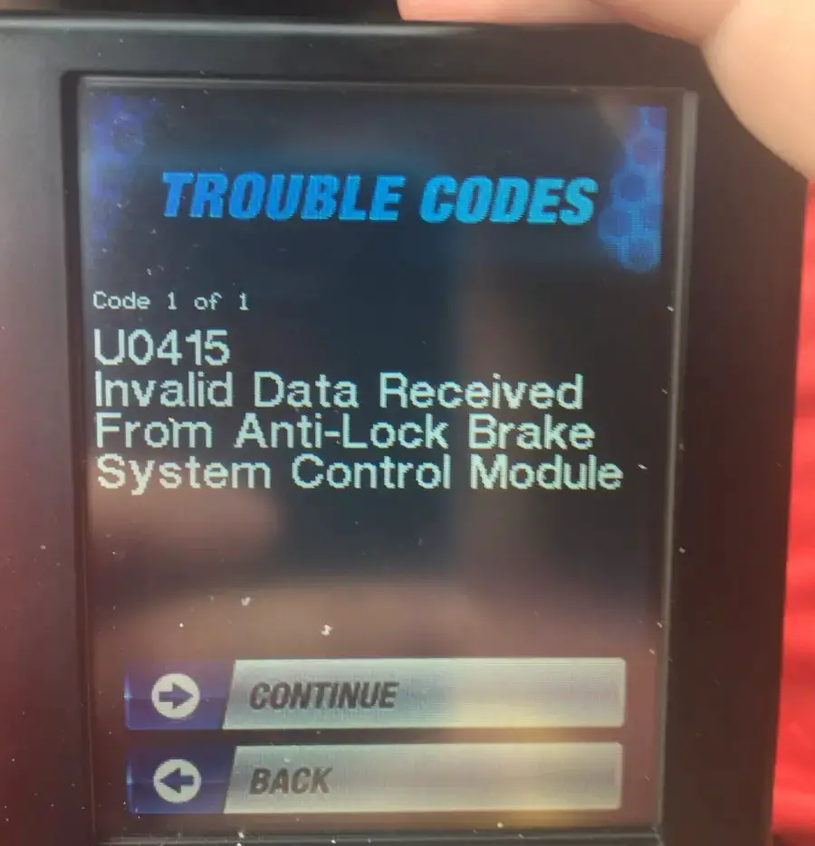
The PCM requires valid data from the ABS system via the wheel speed sensors to control the brake system effectively. If the PCM detects implausible or invalid data from the ABS, it will set the U0415 code and illuminate a warning light. In most cases, the ABS system will be disabled until the fault is corrected.
There may be additional codes related to individual wheel speed sensors, including C0544, C0031, C0045, etc. These codes can help pinpoint specific sensor issues.
While the U0415 code can occur in various vehicles, it is more commonly associated with brands such as Chevrolet, Ford, Dodge (Dart), Mazda, Honda, Jeep, Toyota, GM, Chrysler, and others. Please note that the specific definitions can vary slightly between different brands.
How Severe Is The U0415 Code?
The severity level of the U0415 code is moderate. While it does not pose an immediate safety risk, it can affect the proper functioning of the vehicle’s anti-lock brake system. The ABS system is crucial for maintaining control and stability during braking, especially in emergency situations or on slippery surfaces.
It is not recommended to continue driving with the U0415 code illuminated. When this code is present, the ABS system may be disabled, increasing the risk of wheel lock-up and potential loss of control during braking. It is advisable to have the vehicle inspected and repaired by a qualified technician as soon as possible to restore the ABS functionality and ensure safe driving conditions.
What Are The Symptoms Of The U0415 Code?
When the U0415 code is present, the following symptoms may be observed:
- Check engine light (MIL) ON
- ABS warning light illuminated
- Loss of ABS functionality
- Possible decrease in braking performance
What Are The Causes Of The U0415 Code?
The U0415 code can be caused by various factors, including:
- Wiring or connector issues in the ABS system
- Damaged or faulty ABS control module
- Malfunctioning wheel speed sensors
- Defective ABS pump or valve body
- Faulty PCM (rarely)
It is important to note that these are general causes, and a proper diagnosis is necessary to determine the exact source of the U0415 code in a specific vehicle.
Read more: P1777 Nissan Code: A Practical Repair Guide
How To Diagnose And Fix The U0415 Code In Your Vehicles?
When encountering the U0415 code, a comprehensive diagnostic and repair process can assist in resolving the problem. Here, we provide an outline of the necessary tools and components, a step-by-step guide, and an evaluation of the feasibility of DIY repair:
Essential Tools and Parts
To diagnose and repair the U0415 code, the following tools and parts may be required:
- OBD-II scanner/code reader
- Multimeter
- Wheel speed sensor(s)
- ABS control module (if necessary)
- Wiring repair kit
- Electrical connectors and terminals
- Basic hand tools (wrenches, sockets, etc.)
Step-by-Step Procedure
- Connect an OBD-II scanner/code reader and retrieve the U0415 code and any others.
- Inspect the ABS control module wiring and connectors for any visible damage or loose connections. Repair the issues, if any.
- Test the wheel speed sensors using a multimeter to check for proper resistance and signal output.
- If a faulty wheel speed sensor is identified, replace the sensor as necessary.
- If no issues are found with the wiring or sensors, further diagnosis of the ABS control module may be required.
- Consult the vehicle’s service manual to locate and remove the ABS control module.
- Install a new ABS control module, ensuring all connectors are properly connected. (It is highly recommended to locate a proficient mechanic for the execution of this type of task.)
- Clear the U0415 code with the OBD-II scanner/code reader and test the ABS system for proper functionality.
Note: Consulting your vehicle’s repair manual or seeking expert help is crucial if you have uncertainties about any step in the procedure. Furthermore, ensure to reset any trouble codes post-repairs and engage in a test drive to confirm the resolution of the problem.
Read more: C1109 Nissan Code: ABS Voltage Trouble Exposed
DIY Repair Level And Estimated Costs
The repair procedure for the U0415 code can vary in complexity. Basic tasks such as inspecting wiring and connectors, as well as replacing wheel speed sensors, can be tackled by DIY enthusiasts with intermediate mechanical skills. However, diagnosing and replacing the ABS control module may require advanced knowledge and specialized tools.
Estimated costs for repairs related to the U0415 code can vary widely depending on the specific vehicle and components involved. Here is a table outlining approximate costs:
| Repair Task | Estimated Cost |
| Wheel speed sensor replacement | $50 – $100 |
| ABS control module replacement | $200 – $500 |
| Wiring repair | $50 – $150 |
| Professional diagnosis | $100 – $200 |
Keep in mind that these are rough estimates, and actual costs may differ. Additionally, if unsure or uncomfortable with the repair process, it is recommended to seek assistance from a qualified mechanic to ensure proper diagnosis and repair of the U0415 code.
U0415 Infographic
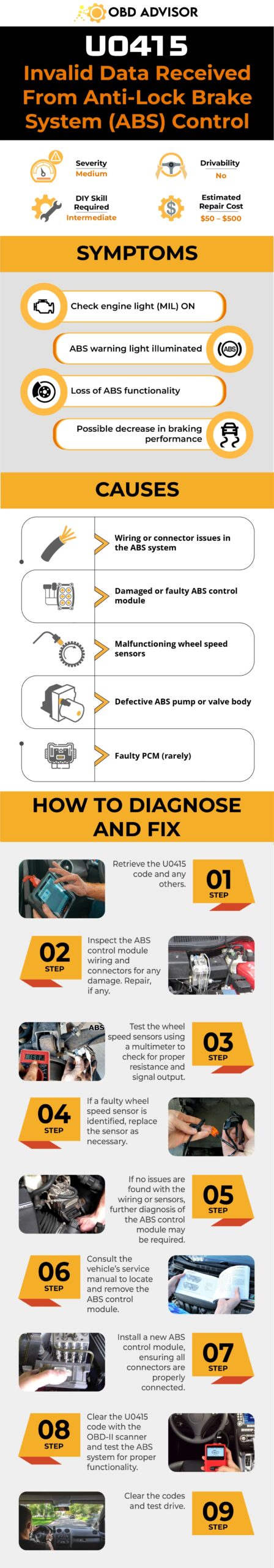
Final Thoughts
And that’s a wrap on understanding the U0415 code! Dealing with car issues might seem tricky, but armed with the right info and tools, you can handle it.
Got questions or stories about this code? Share them in the comments – let’s chat! If this guide helped you, pass it on to pals who love tinkering with cars. Until next time, happy fixing and safe driving!
Learn more about other codes by using our OBD lookup tool!
Reference Sources
- MyCarDoesWhat.org, Anti-lock braking system
- J.D. Power, What is a front-wheel speed sensor?
C1109 Nissan Code: ABS Voltage Trouble Exposed
C1109 Nissan Code: ABS Voltage Trouble Exposed
You’ve come across the C1109 code in your Nissan? Don’t you worry! Prepare to gain insights, solutions, and expert guidance for addressing this unique situation.
In this article, we’ll explore the intricacies of the C1109 code, diving into its effects on your vehicle’s performance. From understanding symptoms to conducting diagnostics, we’ll walk you through each stage, keeping you informed and empowered throughout the process.
C1109 Nissan Code: A Quick Overview
Take a look at the summary of the Nissan C1109 code provided below!
- Definition: Battery Voltage [Abnormal]
- Severity: Medium
- DIY Skill Level: Intermediate
- Continue To Drive?: No
- Estimated Repair Cost: $50 – $300
What Does The C1109 Nissan Code Mean?
The C1109 code in Nissan vehicles points to an issue labeled as “Battery Voltage [Abnormal]” within the Anti-lock Braking System (ABS) actuator and electric unit control (ECU) unit. This alert activates when the voltage being delivered to the ABS system goes outside the standard operational range. Specifically, it triggers when the voltage drops below 10 volts (indicating low ignition voltage) or rises above 16 volts (indicating high ignition voltage).
(Credit: altimaforums.net)
The ABS system in a vehicle is a crucial safety feature that prevents wheel lock-up during heavy braking, enhancing control and stability. The C1109 code alerts the vehicle’s onboard diagnostics system that there is an issue with the battery voltage affecting the ABS control unit. This can lead to compromised performance of the ABS system and potentially impact the vehicle’s braking performance.
The C1109 code can be found in various Nissan models when battery voltage irregularities occur. Some of the Nissan models that are known to experience the C1109 code include Altima, Maxima, Sentra, Rogue, Murano, 370Z, etc.
How Severe Is The C1109 Code On Nissan?
The C1109 code’s severity in Nissan vehicles can vary from moderate to potentially hazardous. Continuing to drive with the C1109 code illuminated could jeopardize braking performance and compromise vehicle stability. It’s strongly advised to avoid driving with this code active.
Get professional inspection and repair are recommended to ensure the ABS functions correctly, maintaining optimal control and safety while driving.
What Are The Signs Of The C1109 Code On Nissan Vehicles?
When the C1109 code surfaces in Nissan vehicles, it comes accompanied by noticeable symptoms that can’t be ignored. Being focused on the signs is crucial for timely diagnosis and resolution. Some of the common symptoms associated with the C1109 code include:
- Illuminated ABS warning light
- Unusual brake pedal feel (sponginess or increased resistance)
- Decreased effectiveness of the ABS system during braking
- Irregularities in vehicle stability during abrupt stops
Read more: P1715 Nissan Code Solved: Tips For Dealing With Transmission Issues
What Are The Causes Of The C1109 Nissan Code?
The underlying triggers behind the C1109 code in Nissan vehicles can be attributed to various components and systems within the vehicle. Understanding these potential causes is key to effectively addressing the issue:
- Faulty harnesses or connectors in the ABS system
- Malfunctioning ABS actuator and ECU
- Blown fuse
- Defective ignition power supply system
- Battery-related issues
How To Diagnose And Fix The C1109 Code On Nissan?
When dealing with the C1109 code, a systematic diagnosis and repair approach can effectively address the issue. Below is a comprehensive breakdown of the process, including essential tools and parts, a detailed step-by-step guide, and a DIY repair assessment:
Essential Tools And Parts
In order to effectively identify and rectify the C1109 code in Nissan vehicle, you will require the subsequent tools and components:
- OBD-II scanner
- Digital multimeter
- Wiring and connectors
- Basic hand tools
- Replacement ABS unit (if required)
- Wiring diagrams
Step-by-Step Procedure
- Code retrieval and initial check
- Use the OBD-II scanner to retrieve the C1109 code and associated freeze frame data.
- Inspect the ABS warning light for illumination.
- Check if there are any noticeable issues with braking performance.
- Visual inspection
- Examine the wiring harnesses and connectors connected to the ABS unit for signs of damage, corrosion, or loose connections.
- Pay special attention to any visible wear on the wiring insulation.
- Replace or repair if necessary.
- Battery voltage test
- With the vehicle’s engine running, use the multimeter to measure the battery voltage.
- Check for voltage fluctuations during engine operation, noting any irregularities.
- Inspect the battery for indications of loose terminals, insufficient voltage, or other anomalies.
- If any components fail, proceed to repair or substitute them accordingly.
- ABS actuator and control unit test
- Disconnect the ABS unit’s electrical connector.
- Use the multimeter to check the resistance and continuity of the connector pins, comparing the readings with manufacturer specifications.
- If the ABS unit or control unit is faulty, consider replacing it with a new or tested one.
- Clearing the code and test drive
- Once repairs are made, use the OBD-II scanner to clear the C1109 code and any associated trouble codes.
- Take the vehicle for a test drive to verify that the ABS system operates correctly and that the code does not return.
Note:
- Ensure proper safety measures are taken, such as disconnecting the vehicle’s battery before working on electrical components.
- Refer to the vehicle’s repair manual and wiring diagrams for accurate information.
Read more: P1217 Nissan Code: Engine Cooling Insights
DIY Repair Level And Estimated Costs
This procedure demands intermediate mechanical skills. While simple tasks like inspecting connectors are feasible for DIY enthusiasts, handling complex electrical components may require professional assistance. Prioritize accuracy and safety. If uncertain, consult a mechanic for a thorough diagnosis and repair.
Take a look at the estimated cost table we have provided for various necessary tasks.
| Repair Task | Estimated Cost |
| Wiring and Connector Repair | $50 – $150 |
| Replacement ABS unit (if required) | $200 – $500 |
This is just a rough estimate. Remember, costs can vary based on factors like location and specific tools chosen. Always gather accurate pricing information before proceeding with repairs.
C1109 Nissan Infographic

Final Thoughts
Having explored this comprehensive article on the C1109 Nissan code, you now have a good insight into this code’s symptoms, causes, and repair procedures. This newfound knowledge empowers you to enhance your vehicle’s performance with confidence.
Share this newfound knowledge with fellow Nissan enthusiasts and join the conversation with your comments and questions below.
Safe drive!
Reference Sources
- NiRogue, Nissan Rogue Service Manual.
- ALLDATAdiy, 2009 Nissan-Datsun Altima V6-3.5L.
Dodge, Chrysler, and Jeep OBD1 Codes and OBD2 Codes [Full PDF Free Download]
Dodge, Chrysler, and Jeep OBD1 Codes and OBD2 Codes [Full PDF Free Download]
Does the illuminating check engine light to your old Dodge, Chrysler, or Jeep leave you crutching your head wondering what the problem might be? Would you like to know how to read OBD1 codes for these models?
If you would like to add a few skills to your sleeves, then you’re in the right place. You could also be curious about how to perform this task, I assure you, you’ll not be disappointed!
In this post, you will learn how to troubleshoot faulty vehicle components for Dodge, Chrysler, and Jeep OBD1 models. You’ll read through the techniques to pulling error codes and eliminating them after the repair is made.
Let’s dig into it!
Dodge, Chrysler, and Jeep OBD1 Codes List
Free Download: Dodge, Chrysler, and Jeep OBD1 Codes List PDF
Note: Use the search box in the table below to quickly find the specific code you’re looking for.
For Domestic Vehicles Codes List
| Code | Definition |
|---|---|
| Code 88 | Display used for start or test(will only be seen using a DRB2 scanner) |
| Code 11 | Crankshaft signal or ignition signal, no reference signal during cranking |
| Code 12 | Memory to controller has been cleared within 50-100 engine starts |
| Code 13 | MAP sensor vacuum, no change from start to run or output voltage does not equal throttle position |
| Code 14 | MAP voltage too high or too low |
| Code 15 | Vehicle speed sensor, no signal detected |
| Code 16 | Loss of battery voltage sense |
| Code 17 | Low engine temperature, possible thermostat fault |
| Code 21 | Oxygen sensor signal, neither rich or lean detected or O2 shorted to voltage |
| Code 21 | Knock sensor circuit(starting in 89) |
| Code 22 | Coolant temp sensor voltage low/high |
| Code 23 | Air charge temp sensor voltage high/low detected |
| Code 24 | Throttle position sensor voltage high/low |
| Code 25 | Automatic idle speed motor driver circuit, short or open detected |
| Code 26 | Injectors 1,2,3 peak current not reached, problem in injector control circuits cylinder 1 and/or 2. |
| Code 27 | Injector control circuit does not respond to control signal, problem in injector control circuits 3 and/or 4 |
| Code 31 | Purge solenoid circuit, open or short detected |
| Code 32 | EGR solenoid circuit, open or short detected |
| Code 33 | A/C clutch relay circuit, open or short detected |
| Code 34 | Speed control servo solenoid, open or short detected |
| Code 35 | Radiator fan control relay circuit, open or short detected |
| Code 36 | Wastegate solenoid, open or short detected |
| Code 37 | Baro read solenoid |
| Code 37 | PTU solenoid circuit(starting in 89) |
| Code 41 | Charging system circuit not responding to control signal, alternator field circuit not switching properly |
| Code 42 | Fuel pump or auto shutdown (ASD) relay voltage sensed at controller |
| Code 42 | Z1 voltage sense |
| Code 43 | Ignition control circuit not responding |
| Code 44 | Battery temperature voltage circuit problem |
| Code 45 | Turbo boost limit exceeded-map sensor detects overboost |
| Code 46 | Battery voltage too high..overcharging |
| Code 47 | Battery voltage too low…battery voltage low or charging output low |
| Code 51 | Air/fuel at limit |
| Code 51 | Lean exhaust indication, O2 voltage latched below .450 volts |
| Code 52 | Rich exhaust indication, O2 voltage latched above .450 volts |
| Code 53 | Internal controller failure (normal code on a re-calibrated controller) |
| Code 54 | Fuel sync signal not detected during cranking |
| Code 55 | End of message |
| Code 61 | Baro read solenoid, open or short detected |
| Code 62 | EMR mileage not stored |
| Code 63 | EEPROM write denied |
| Code 64 | Flex fuel sensor signal out of range |
| Code 64 | VNT solenoid #1 circuit |
| Code 65 | Manifold tuning valve, open or short detected |
| Code 65 | VNT solenoid #2 circuit |
| Code 66 | No CCD messages |
| Code 67 | VNT “A” side failure |
| Code 76 | Ballast bypass relay, open or short detected |
| Code 77 | Speed control relay, open or short detected |
For Import Vehicles Codes List
| Code | Definition |
|---|---|
| Code 1 | Oxygen sensor |
| Code 2 | Crank engine sensor |
| Code 3 | Air flow sensor |
| Code 4 | Barometric pressure sensor |
| Code 5 | Throttle position sensor |
| Code 6 | Motor position sensor |
| Code 7 | Engine coolant temperature sensor |
| Code 8 | No.1 cylinder TDC sensor |
| Code 12 | Air flow sensor |
| Code 13 | Air temperature sensor |
| Code 14 | Throttle position sensor |
| Code 15 | SC motor position sensor |
| Code 21 | Engine coolant temperature sensor |
| Code 22 | Crank angle sensor |
| Code 23 | No.1 cylinder TDC sensor |
| Code 24 | Vehicle speed sensor |
| Code 25 | Barometric pressure sensor |
| Code 31 | Knock sensor |
| Code 32 | Manifold pressure sensor |
| Code 36 | Ignition timing adjustment signal |
| Code 39 | Oxygen sensor |
| Code 41 | Injector |
| Code 42 | Fuel pump |
| Code 43 | EGR |
| Code 44 | Ignition coil |
| Code 52 | Ignition coil |
| Code 53 | Ignition coil |
| Code 55 | IAC valve position sensor |
| Code 59 | Heated oxygen sensor |
| Code 61 | Transaxle control unit cable |
| Code 62 | Warm up control valve position sensor |
Dodge, Chrysler OBD2 Codes List [Free Download]
Free Download: Full Dodge, Chrysler OBD2 Codes List PDF
Our user-friendly code list is divided into four parts: P, U, B, and C, which helps you easily find the codes you need for engine, network, body control, and chassis issues.
Note: Use the search box in the table below to quickly find the specific code you’re looking for.
Powertrain (P) Codes List
| Code | Definition |
|---|---|
| P0030 | HO2S Heater Control Circuit Bank 1 Sensor 1 |
| P0031 | HO2S Heater Circuit Low Voltage Bank 1 Sensor 1 |
| P0032 | HO2S Heater Circuit High Voltage Bank 1 Sensor 1 |
| P0036 | HO2S Heater Control Circuit Bank 1 Sensor 2 |
| P0037 | HO2S Heater Circuit Low Voltage Bank 1 Sensor 2 |
| P0038 | HO2S Heater Circuit High Voltage Bank 1 Sensor 2 |
| P0050 | HO2S Heater Circuit Bank 2 Sensor 1 |
| P0051 | HO2S Heater Circuit Low Voltage Bank 2 Sensor 1 |
| P0052 | HO2S Heater Circuit High Voltage Bank 2 Sensor 1 |
| P0056 | HO2S Heater Circuit Bank 2 Sensor 2 |
| P0057 | HO2S Heater Circuit Low Voltage Bank 2 Sensor 2 |
| P0058 | HO2S Heater Circuit High Voltage Bank 2 Sensor 2 |
| P0100 | MAF Sensor Ckt. Insufficient Activity |
| P0101 | Mass Air Flow (MAF) Sensor Performance |
| P0102 | Mass Air Flow (MAF) Sensor Circuit Low Frequency |
| P0103 | Mass Air Flow (MAF) Sensor Circuit High Frequency |
| P0104 | Mass Air Flow Circuit Intermittent |
| P0105 | MAP Sensor Circuit Insufficient Activity |
| P0106 | Manifold Absolute Pressure (MAP) System Performance |
| P0107 | Manifold Absolute Pressure (MAP) Sensor Circuit Low Voltage |
| P0108 | Manifold Absolute Pressure (MAP) Sensor Circuit High Voltage |
| P0109 | Manifold Absolute Pressure Circuit Intermittent |
| P0110 | Intake Air Temperature (IAT) Sensor Circuit |
| P0111 | Intake Air Temperature (IAT) Sensor Performance |
| P0112 | Intake Air Temperature (IAT) Sensor Circuit Low Voltage |
| P0113 | Intake Air Temperature (IAT) Sensor Circuit High Voltage |
| P0114 | Intake Air Temperature Circuit Intermittent |
| P0115 | Engine Coolant Temperature (ECT) Sensor Circuit |
| P0116 | Engine Coolant Temperature (ECT) Sensor Performance |
| P0117 | Engine Coolant Temperature (ECT) Sensor Circuit Low Voltage |
| P0118 | Engine Coolant Temperature (ECT) Sensor Circuit High Voltage |
| P0119 | Engine Coolant Temperature Circuit Intermittent |
| P0120 | Throttle Position System Performance |
| P0121 | Throttle Position Sensor Circuit Insufficient Activity |
| P0122 | Throttle Position (TP) Sensor Circuit Low Voltage |
| P0123 | Throttle Position (TP) Sensor Circuit High Voltage |
| P0124 | Throttle Position Sensor 1 Circuit Intermittent |
| P0125 | Engine Coolant Temperature (ECT) Insufficient for Closed Loop Fuel Control |
| P0126 | Insufficient Engine Coolant Temperature for Stable Operation |
| P0128 | Coolant Thermostat |
| P0130 | HO2S Circuit Closed Loop (CL) Performance Bank 1 Sensor 1 |
| P0131 | HO2S Circuit Low Voltage Bank 1 Sensor 1 |
| P0132 | HO2S Circuit High Voltage Bank 1 Sensor 1 |
| P0133 | HO2S Slow Response Bank 1 Sensor 1 |
| P0134 | HO2S Circuit Insufficient Activity Bank 1 Sensor 1 |
| P0135 | HO2S Heater Performance Bank 1 Sensor 1 |
| P0136 | HO2S Circuit Bank 1 Sensor 2 |
| P0137 | HO2S Circuit Low Voltage Bank 1 Sensor 2 |
| P0138 | HO2S Circuit High Voltage Bank 1 Sensor 2 |
| P0139 | HO2S Slow Response Bank 1 Sensor 2 |
| P0140 | HO2S Circuit Insufficient Activity Bank 1 Sensor 2 |
| P0141 | HO2S Heater Performance Bank 1 Sensor 2 |
| P0142 | HO2S Circuit Bank 1 Sensor 3 |
| P0143 | HO2S Circuit Low Voltage Bank 1 Sensor 3 |
| P0144 | HO2S Circuit High Voltage Bank 1 Sensor 3 |
| P0145 | HO2S Circuit Bank 1 Sensor 2 Slow Response |
| P0146 | HO2S Circuit Insufficient Activity Bank 1 Sensor 3 |
| P0147 | HO2S Heater Performance Bank 1 Sensor 3 |
| P0150 | HO2S Circuit Closed Loop (CL) Performance Bank 2 Sensor 1 |
| P0150 | HO2S Circuit Bank 2 Sensor 1 |
| P0151 | HO2S Circuit Low Voltage Bank 2 Sensor 1 |
| P0152 | HO2S Circuit High Voltage Bank 2 Sensor 1 |
| P0153 | HO2S Slow Response Bank 2 Sensor 1 |
| P0154 | HO2S Circuit Insufficient Activity Bank 2 Sensor 1 |
| P0155 | HO2S Heater Performance Bank 2 Sensor 1 |
| P0156 | HO2S Circuit Bank 2 Sensor 2 |
| P0157 | HO2S Circuit Low Voltage Bank 2 Sensor 2 |
| P0158 | HO2S Circuit High Voltage Bank 2 Sensor 2 |
| P0159 | HO2S Slow Response Bank 2 Sensor 2 |
| P0160 | HO2S Circuit Insufficient Activity Bank 2 Sensor 2 |
| P0161 | HO2S Heater Performance Bank 2 Sensor 2 |
| P0162 | HO2S Circuit Bank 2 Sensor 3 |
| P0163 | HO2S Circuit Bank 2 Sensor 3 Low Voltage |
| P0164 | HO2S Circuit Bank 2 Sensor 3 High Voltage |
| P0165 | HO2S Circuit Bank 2 Sensor 3 Slow Response |
| P0166 | HO2S Circuit Bank 2 Sensor 3 No Activity Detected |
| P0167 | HO2S Heater Circuit Bank 2 Sensor 3 |
| P0169 | Fuel Composition Sensor |
| P0170 | Fuel Trim Bank 1 |
| P0171 | Fuel Trim System Lean Bank 1 |
| P0172 | Fuel Trim System Rich Bank 1 |
| P0173 | Fuel Trim Bank 2 |
| P0174 | Fuel Trim System Lean Bank 2 |
| P0175 | Fuel Trim System Rich Bank 2 |
| P0176 | Fuel Composition Sensor Circuit |
| P0177 | Fuel Composition Sensor Circuit Performance |
| P0178 | Fuel Composition Sensor Circuit Low Voltage |
| P0179 | Fuel Composition Sensor Circuit High Voltage |
| P0180 | Fuel Temperature Sensor 1 Circuit |
| P0181 | Fuel Temp. Sensor 1 Circuit Performance |
| P0182 | Fuel Temperature Sensor Circuit Low Voltage |
| P0183 | Fuel Temperature Sensor Circuit High Voltage |
| P0184 | Fuel Temperature Sensor 1 Circuit Intermittent |
| P0185 | Fuel Temperature Sensor 2 Circuit |
| P0186 | Fuel Temp. Sensor 2 Circuit Performance |
| P0187 | Fuel Temperature Sensor 2 Circuit Low Voltage |
| P0188 | Fuel Temperature Sensor 2 Circuit High Voltage |
| P0189 | Fuel Temperature Sensor 2 Circuit Intermittent |
| P0190 | Fuel Rail Pressure Sensor Circuit |
| P0191 | Fuel Rail Pressure Sensor Circuit Performance |
| P0192 | Fuel Rail Pressure Sensor Circuit Low Voltage |
| P0193 | Fuel Rail Pressure Sensor Circuit High Voltage |
| P0194 | Fuel Rail Pressure Sensor Circuit Intermittent |
| P0195 | Engine Oil Temperature Sensor |
| P0196 | Engine Oil Temperature Sensor Performance |
| P0197 | Engine Oil Temperature Sensor Low Voltage |
| P0198 | Engine Oil Temperature Sensor High Voltage |
| P0199 | Engine Oil Temperature Sensor Intermittent |
| P0200 | Injector Control Circuit |
| P0201 | Injector 1 Control Circuit |
| P0202 | Injector 2 Control Circuit |
| P0203 | Injector 3 Control Circuit |
| P0204 | Injector 4 Control Circuit |
| P0205 | Injector 5 Control Circuit |
| P0206 | Injector 6 Control Circuit |
| P0207 | Injector 7 Control Circuit |
| P0208 | Injector 8 Control Circuit |
| P0209 | Injector 9 Control Circuit |
| P0210 | Injector 10 Control Circuit |
| P0211 | Injector 11 Control Circuit |
| P0212 | Injector 12 Control Circuit |
| P0213 | Cold Start Injector 1 |
| P0214 | Cold Start Injector 2 |
| P0215 | Engine Shutoff Control Circuit |
| P0216 | Injection Timing Control Circuit |
| P0217 | Engine Overtemp Condition |
| P0218 | Transmission Fluid Overtemperature |
| P0219 | Engine Overspeed Condition |
| P0220 | APP Sensor 2 Circuit |
| P0221 | APP (Throttle Position) Sensor 2 Circuit Performance |
| P0222 | APP (Throttle Position) Sensor 2 Circuit Low Voltage |
| P0223 | APP (Throttle Position) Sensor 2 Circuit High Voltage |
| P0224 | Throttle Position Sensor 2 Intermittent |
| P0225 | APP Sensor 3 Circuit |
| P0226 | APP Sensor 3 Circuit Performance |
| P0227 | APP Sensor 3 Circuit Low Voltage |
| P0228 | APP Sensor 3 Circuit High Voltage |
| P0229 | Throttle Position Sensor 3 Intermittent |
| P0230 | Fuel Pump Relay Control Circuit |
| P0231 | Fuel Pump Feedback Circuit Low Voltage |
| P0232 | Fuel Pump Feedback Circuit High Voltage |
| P0233 | Fuel Pump Secondary Circuit Intermittent |
| P0234 | TC Engine Overboost Condition |
| P0235 | Turbocharger Boost Sensor 1 Circuit |
| P0236 | TC Boost System |
| P0237 | TC Boost Sensor Circuit Low Voltage |
| P0238 | TC Boost Sensor Circuit High Voltage |
| P0239 | Turbocharger Boost Sensor 2 Circuit |
| P0240 | Turbocharger Boost Sensor 2 Performance |
| P0241 | Turbocharger Boost Sensor 2 Circuit Low Voltage |
| P0242 | Turbocharger Boost Sensor 2 Circuit High Voltage |
| P0243 | Turbocharger Wastegate Solenoid 1 |
| P0244 | Turbocharger Wastegate Solenoid 1 Performance |
| P0245 | Turbocharger Wastegate Solenoid 1 Low Voltage |
| P0246 | Turbocharger Wastegate Solenoid 1 High Voltage |
| P0247 | Turbocharger Wastegate Solenoid 2 |
| P0248 | Turbocharger Wastegate Solenoid 2 Performance |
| P0249 | Turbocharger Wastegate Solenoid 2 Low Voltage |
| P0250 | Turbocharger Wastegate Solenoid 2 High Voltage |
| P0251 | Injection Pump Fuel Metering Control “A” Malfunction (Cam/Rotor/Injector) |
| P0252 | Injection Pump Fuel Metering Control “A” Range/Performance (Cam/Rotor/Injector) |
| P0253 | Injection Pump Fuel Metering Control “A” Low (Cam/Rotor/Injector) |
| P0254 | Injection Pump Fuel Metering Control “A” High (Cam/Rotor/Injector) |
| P0255 | Injection Pump Fuel Metering Control “A” Intermittent (Cam/Rotor/Injector) |
| P0256 | Injection Pump Fuel Metering Control “B” Malfunction (Cam/Rotor/Injector) |
| P0257 | Injection Pump Fuel Metering Control “B” Range/Performance (Cam/Rotor/Injector) |
| P0258 | Injection Pump Fuel Metering Control “B” Low (Cam/Rotor/Injector) |
| P0259 | Injection Pump Fuel Metering Control “B” High (Cam/Rotor/Injector) |
| P0260 | Injection Pump Fuel Metering Control “B” Intermittent (Cam/Rotor/Injector) |
| P0261 | Cylinder 1 Injector Circuit Low |
| P0262 | Cylinder 1 Injector Circuit High |
| P0263 | Cylinder 1 Contribution/Balance Fault |
| P0264 | Cylinder 2 Injector Circuit Low |
| P0265 | Cylinder 2 Injector Circuit High |
| P0266 | Cylinder 2 Contribution/Balance Fault |
| P0267 | Cylinder 3 Injector Circuit Low |
| P0268 | Cylinder 3 Injector Circuit High |
| P0269 | Cylinder 3 Contribution/Balance Fault |
| P0270 | Cylinder 4 Injector Circuit Low |
| P0271 | Cylinder 4 Injector Circuit High |
| P0272 | Cylinder 4 Contribution/Balance Fault |
| P0273 | Cylinder 5 Injector Circuit Low |
| P0274 | Cylinder 5 Injector Circuit High |
| P0275 | Cylinder 5 Contribution/Balance Fault |
| P0276 | Cylinder 6 Injector Circuit Low |
| P0277 | Cylinder 6 Injector Circuit High |
| P0278 | Cylinder 6 Contribution/Balance Fault |
| P0279 | Cylinder 7 Injector Circuit Low |
| P0280 | Cylinder 7 Injector Circuit High |
| P0281 | Cylinder 7 Contribution/Balance Fault |
| P0282 | Cylinder 8 Injector Circuit Low |
| P0283 | Cylinder 8 Injector Circuit High |
| P0284 | Cylinder 8 Contribution/Balance Fault |
| P0285 | Cylinder 9 Injector Circuit Low |
| P0286 | Cylinder 9 Injector Circuit High |
| P0287 | Cylinder 9 Contribution/Balance Fault |
| P0288 | Cylinder 10 Injector Circuit Low |
| P0289 | Cylinder 10 Injector Circuit High |
| P0290 | Cylinder 10 Contribution/Balance Fault |
| P0291 | Cylinder 11 Injector Circuit Low |
| P0292 | Cylinder 11 Injector Circuit High |
| P0293 | Cylinder 11 Contribution/Balance Fault |
| P0294 | Cylinder 12 Injector Circuit Low |
| P0295 | Cylinder 12 Injector Circuit High |
| P0296 | Cylinder 12 Contribution/Range Fault |
| P0300 | Engine Misfire Detected |
| P0301 | Cylinder 1 Misfire Detected |
| P0302 | Cylinder 2 Misfire Detected |
| P0303 | Cylinder 3 Misfire Detected |
| P0304 | Cylinder 4 Misfire Detected |
| P0305 | Cylinder 5 Misfire Detected |
| P0306 | Cylinder 6 Misfire Detected |
| P0307 | Cylinder 7 Misfire Detected |
| P0308 | Cylinder 8 Misfire Detected |
| P0309 | Cylinder 9 Misfire Detected |
| P0311 | Cylinder 11 Misfire Detected |
| P0312 | Cylinder 12 Misfire Detected |
| P0313 | Misfire Detected With Low Fuel Level |
| P0318 | Rough Road Sensor Circuit |
| P0320 | Ignition/Distributor Engine Speed Input Circuit Malfunction |
| P0321 | Ignition/Distributor Engine Speed Input Circuit Range/Performance |
| P0322 | IC Module 4X Reference CKT No Frequency |
| P0323 | Ignition/Distributor Engine Speed Input Circuit Intermittent |
| P0324 | Knock Sensor (KS) Module Performance |
| P0325 | PCM Knock Sensor Circuit |
| P0326 | Knock Sensor CKT Excessive Spark Retard |
| P0327 | Knock Sensor Circuit Low Voltage |
| P0328 | Knock Sensor 1 Circuit High Input (Bank 1 or Single Sensor) |
| P0329 | Knock Sensor 1 Circuit Intermittent (Bank 1 or Single Sensor) |
| P0330 | Knock Sensor (KS) Circuit Bank 2 |
| P0331 | Knock Sensor 2 Circuit Range/Performance (Bank 2) |
| P0332 | Knock Sensor 2 Circuit Low Input (Bank 2) |
| P0333 | Knock Sensor 2 Circuit High Input (Bank 2) |
| P0334 | Knock Sensor 2 Circuit Intermittent (Bank 2) |
| P0335 | CKP Sensor A Circuit Performance |
| P0336 | Crankshaft Position (CKP) Sensor A Performance |
| P0337 | Crankshaft Position (CKP) Sensor Circuit Low Duty Cycle |
| P0338 | Crankshaft Position (CKP) Sensor Circuit High Duty Cycle |
| P0339 | Crankshaft Position (CKP) Sensor Circuit Intermittent |
| P0340 | Camshaft Position (CMP) Sensor Circuit |
| P0341 | Camshaft Position (CMP) Sensor Performance |
| P0342 | Camshaft Position Sensor Circuit Low Input |
| P0343 | Camshaft Position Sensor Circuit High Input |
| P0344 | Camshaft Position Sensor Circuit Intermittent |
| P0350 | Ignition Coil Primary/Secondary Circuit Malfunction |
| P0351 | Ignition Coil 1 Control Circuit |
| P0352 | Ignition Coil 2 Control Circuit |
| P0353 | Ignition Coil 3 Control Circuit |
| P0354 | Ignition Coil 4 Control Circuit |
| P0355 | Ignition Coil 5 Control Circuit |
| P0356 | Ignition Coil 6 Control Circuit |
| P0357 | Ignition Coil 7 Control Circuit |
| P0358 | Ignition Coil 8 Control Circuit |
| P0359 | Ignition Coil I Primary/Secondary Circuit Malfunction |
| P0360 | Ignition Coil J Primary/Secondary Circuit Malfunction |
| P0361 | Ignition Coil K Primary/Secondary Circuit Malfunction |
| P0362 | Ignition Coil L Primary/Secondary Circuit Malfunction |
| P0370 | Timing Reference High Resolution Signal A Malfunction |
| P0371 | IC 24X Reference CKT Too Many Pulses |
| P0372 | IC 24X Reference Circuit Missing Pulses |
| P0373 | Timing Reference High Resolution Signal A Intermittent/Erratic Pulses |
| P0374 | Timing Reference High Resolution Signal A No Pulses |
| P0375 | Timing Reference High Resolution Signal B Malfunction |
| P0376 | Timing Reference High Resolution Signal B Too Many Pulses |
| P0377 | Timing Reference High Resolution Signal B Too Few Pulses |
| P0378 | Timing Reference High Resolution Signal B Intermittent/Erratic Pulses |
| P0379 | Timing Reference High Resolution Signal B No Pulses |
| P0380 | Glow Plug/Heater Circuit “A” Malfunction |
| P0381 | Glow Plug/Heater Indicator Circuit Malfunction |
| P0382 | Exhaust Gas Recirculation Flow Malfunction |
| P0385 | Crankshaft Position (CKP) Sensor B Circuit |
| P0386 | Crankshaft Position (CKP) Sensor B Performance |
| P0387 | Crankshaft Position Sensor B Circuit Low Input |
| P0388 | Crankshaft Position Sensor B Circuit High Input |
| P0389 | Crankshaft Position Sensor B Circuit Intermittent |
| P0400 | Exhaust Gas Recirculation Flow Malfunction |
| P0401 | Exhaust Gas Recirculation (EGR) Flow Insufficient |
| P0402 | Exhaust Gas Recirculation Flow Excessive Detected |
| P0403 | Exhaust Gas Recirculation (EGR) Solenoid Control Circuit |
| P0404 | Exhaust Gas Recirculation (EGR) Open Position Performance |
| P0405 | Exhaust Gas Recirculation (EGR) Position Sensor Circuit Low Voltage |
| P0406 | Exhaust Gas Recirculation Sensor A Circuit High |
| P0407 | Exhaust Gas Recirculation Sensor B Circuit Low |
| P0408 | Exhaust Gas Recirculation Sensor B Circuit High |
| P0410 | Secondary Air Injection (AIR) System |
| P0411 | Secondary Air Injection (AIR) System |
| P0412 | Secondary Air Injection (AIR) Solenoid Relay Control Circuit Bank 1 |
| P0413 | Secondary Air Injection System Switching Valve A Circuit Open |
| P0414 | Secondary Air Injection System Switching Valve A Circuit Shorted |
| P0415 | Secondary Air Injection System Switching Valve B Circuit Malfunction |
| P0416 | Secondary Air Injection System Switching Valve B Circuit Open |
| P0417 | Secondary Air Injection System Switching Valve B Circuit Shorted |
| P0418 | Secondary Air Injection (AIR) Pump Relay Control Circuit Bank 1 |
| P0419 | Secondary Air Injection (AIR) Pump Relay Control Circuit Bank 2 |
| P0420 | Catalyst System Low Efficiency |
| P0421 | Warm Up Catalyst Efficiency Below Threshold (Bank 1) |
| P0422 | Catalyst System Low Efficiency Bank 1 |
| P0423 | Heated Catalyst Efficiency Below Threshold (Bank 1) |
| P0424 | Heated Catalyst Temperature Below Threshold (Bank 1) |
| P0430 | Catalyst System Low Efficiency Bank 2 |
| P0431 | Warm Up Catalyst Efficiency Below Threshold (Bank 2) |
| P0432 | Catalyst System Low Efficiency Bank 2 |
| P0433 | Heated Catalyst Efficiency Below Threshold (Bank 2) |
| P0434 | Heated Catalyst Temperature Below Threshold (Bank 2) |
| P0440 | Evaporative Emission (EVAP) System |
| P0441 | Evaporative Emission Control System Incorrect Purge Flow |
| P0442 | Evaporative Emission (EVAP) System Small Leak Detected |
| P0443 | EVAP Purge Solenoid Valve 1 Control CKT |
| P0444 | Evaporative Emission Control System Purge Control Valve Circuit Open |
| P0445 | Evaporative Emission Control System Purge Control Valve Circuit Shorted |
| P0446 | EVAP Vent Solenoid Valve Control System |
| P0447 | Evaporative Emission Control System Vent Control Circuit Open |
| P0448 | Evaporative Emission Control System Vent Control Circuit Shorted |
| P0449 | Evaporative Emission (EVAP) Vent Solenoid Control Circuit |
| P0450 | Fuel Tank Pressure Sensor Circuit |
| P0451 | Evaporative Emission Control System Pressure Sensor Range/Performance |
| P0452 | Fuel Tank Pressure Sensor Circuit Low Voltage |
| P0453 | Fuel Tank Pressure Sensor Circuit High Voltage |
| P0454 | Evaporative Emission Control System Pressure Sensor Intermittent |
| P0455 | Evaporative Emission (EVAP) System Leak Detected |
| P0460 | Fuel Level Sensor Circuit |
| P0461 | Fuel Level Sensor Performance |
| P0462 | Fuel Level Sensor Circuit Low Voltage |
| P0463 | Fuel Level Sensor Circuit High Voltage |
| P0464 | Fuel Level Sensor Circuit Intermittent |
| P0465 | Purge Flow Sensor Circuit Malfunction |
| P0466 | Purge Flow Sensor Circuit Range/Performance |
| P0467 | Purge Flow Sensor Circuit Low Input |
| P0468 | Purge Flow Sensor Circuit High Input |
| P0469 | Purge Flow Sensor Circuit Intermittent |
| P0470 | Exhaust Pressure Sensor Malfunction |
| P0471 | Exhaust Pressure Sensor Range/Performance |
| P0472 | Exhaust Pressure Sensor Low |
| P0473 | Exhaust Pressure Sensor High |
| P0474 | Exhaust Pressure Sensor Intermittent |
| P0475 | Exhaust Pressure Control Valve Malfunction |
| P0476 | Exhaust Pressure Control Valve Range/Performance |
| P0477 | Exhaust Pressure Control Valve Low |
| P0478 | Exhaust Pressure Control Valve High |
| P0479 | Exhaust Pressure Control Valve Intermittent |
| P0480 | Cooling Fan Relay 1 Control Circuit |
| P0481 | Cooling Fan Relay 2 Control Circuit |
| P0482 | Cooling Fan 3 Control Circuit Malfunction |
| P0483 | Cooling Fan Rationality Check Malfunction |
| P0484 | Cooling Fan Circuit Over Current |
| P0485 | Cooling Fan Power/Ground Circuit Malfunction |
| P0496 | Evaporative Emission (EVAP) System Flow During Non-Purge |
| P0500 | Vehicle Speed Sensor (VSS) Circuit |
| P0501 | Vehicle Speed Sensor Range/Performance |
| P0502 | Vehicle Speed Sensor (VSS) Circuit Low Input |
| P0503 | Vehicle Speed Sensor (VSS) Circuit Intermittent |
| P0505 | Idle Control System Malfunction |
| P0506 | Idle Speed Low |
| P0507 | Idle Speed High |
| P0510 | Closed Throttle Position Switch Malfunction |
| P0512 | Start Switch Circuit |
| P0520 | Engine Oil Pressure Sensor/Switch Circuit Malfunction |
| P0521 | Engine Oil Pressure Sensor/Switch Circuit Range/Performance |
| P0522 | Engine Oil Pressure Sensor/Switch Circuit Low Voltage |
| P0523 | Engine Oil Pressure Sensor/Switch Circuit High Voltage |
| P0530 | A/C Refrigerant Pressure Sensor Circuit Malfunction |
| P0531 | A/C Refrigerant Pressure Sensor Circuit Range/Performance |
| P0532 | Air Conditioning (A/C) Refrigerant Pressure Sensor Circuit Low Voltage |
| P0533 | Air Conditioning (A/C) Refrigerant Pressure Sensor Circuit High Voltage |
| P0534 | Air Conditioner Refrigerant Charge Loss |
| P0550 | Power Steering Pressure (PSP) Switch Circuit |
| P0551 | Power Steering Pressure Sensor Circuit Range/Performance |
| P0552 | Power Steering Pressure Sensor Circuit Low Input |
| P0553 | Power Steering Pressure Sensor Circuit High Input |
| P0554 | Power Steering Pressure Sensor Circuit Intermittent |
| P0560 | System Voltage |
| P0561 | System Voltage Unstable |
| P0562 | System Voltage Low |
| P0563 | System Voltage High |
| P0565 | Cruise Control On Signal Malfunction |
| P0566 | Cruise Control Off Signal Malfunction |
| P0567 | Cruise Control Resume Signal Malfunction |
| P0568 | Cruise Control Set Signal Malfunction |
| P0569 | Cruise Control Coast Signal Malfunction |
| P0570 | Cruise Control Accel Signal Malfunction |
| P0571 | Cruise Control Brake Switch Circuit |
| P0573 | Cruise Control/Brake Switch A Circuit High |
| P0574 | Vehicle Speed Too High – Cruise Control Disabled |
| P0575 | Cruise Control Related Malfunction |
| P0576 | Cruise Control Related Malfunction |
| P0576 | Cruise Control Related Malfunction |
| P0578 | Cruise Control Related Malfunction |
| P0579 | Cruise Control Related Malfunction |
| P0580 | Cruise Control Related Malfunction |
| P0600 | Serial Communication Link Malfunction |
| P0601 | Control Module Read Only Memory (ROM) |
| P0602 | Control Module Not Programmed |
| P0603 | Control Module Long Term Memory Reset |
| P0604 | Control Module Random Access Memory (RAM) |
| P0605 | Control Module Programming Read Only Memory (ROM) |
| P0606 | Control Module Internal Performance |
| P0607 | ECU Malfunction |
| P0608 | Control Module VSS Output “A” Malfunction |
| P0609 | Control Module VSS Output “B” Malfunction |
| P0610 | Control Module Vehicle Options Incorrect |
| P0615 | Starter Relay Control Circuit |
| P0616 | Starter Relay Control Circuit Low Voltage |
| P0617 | Starter Relay Control Circuit High Voltage |
| P0620 | Generator Control Circuit Malfunction |
| P0621 | Generator L-Terminal Circuit |
| P0622 | Generator F-Terminal Circuit |
| P0625 | Generator F-Terminal Circuit Low Voltage |
| P0626 | Generator F-Terminal Circuit High Voltage |
| P0628 | Fuel Pump Relay Control Circuit Low Voltage |
| P0629 | Fuel Pump Relay Control Circuit High Voltage |
| P0638 | Throttle Actuator Control (TAC) Command Performance |
| P0645 | Air Conditioning (A/C) Clutch Relay Control Circuit |
| P0646 | Air Conditioning (A/C) Clutch Relay Control Circuit |
| P0647 | Air Conditioning (A/C) Clutch Relay Control Circuit |
| P0650 | Malfunction Indicator Lamp (MIL) Control Circuit |
| P0654 | Engine RPM Output Circuit Malfunction |
| P0655 | Engine Hot Lamp Output Control Circuit Malfucntion |
| P0656 | Fuel Level Output Circuit Malfunction |
| P0660 | Intake Manifold Tuning (IMT) Valve Solenoid Control Circuit |
| P0661 | Intake Manifold Tuning (IMT) Valve Solenoid Control Circuit Low Voltage |
| P0662 | Intake Manifold Tuning (IMT) Valve Solenoid Control Circuit High Voltage |
| P0691 | Cooling Fan Relay Control Circuit Low Voltage |
| P0693 | Cooling Fan Relay Control Circuit Low Voltage |
| P0692 | Cooling Fan Relay Control Circuit High Voltage |
| P0694 | Cooling Fan Relay Control Circuit High Voltage |
| P0700 | Transmission Control System Malfunction |
| P0701 | Transmission Control System Range/Performance |
| P0702 | Transmission Control System Electrical |
| P0703 | Brake Switch Circuit Malfunction |
| P0704 | Clutch Switch Input Circuit Malfunction |
| P0705 | Trans Range Switch Circuit |
| P0706 | Trans Range Switch Performance |
| P0707 | Transmission Range Sensor Circuit Low Input |
| P0708 | Transmission Range Sensor Circuit High Input |
| P0709 | Transmission Range Sensor Circuit Intermittent |
| P0710 | Transmission Fluid Temperature Sensor Circuit Malfunction |
| P0711 | TFT Sensor Circuit Range/Performance |
| P0712 | Transmission Fluid Temperature (TFT) Sensor Circuit Low Input |
| P0713 | Transmission Fluid Temperature (TFT) Sensor Circuit High Input |
| P0714 | Transmission Fluid Temperature Sensor Circuit Intermittent |
| P0715 | Input/Turbine Speed Sensor Circuit Malfunction |
| P0716 | Input Speed Sensor Circuit Intermittent |
| P0717 | Input Speed Sensor Circuit Low Input |
| P0718 | Input/Turbine Speed Sensor Circuit Intermittent |
| P0719 | Brake Switch Circuit Low Input |
| P0720 | Output Speed Sensor Circuit Malfunction |
| P0721 | Output Speed Sensor Range/Performance |
| P0722 | Output Speed Sensor Circuit Low Input |
| P0723 | Output Speed Sensor Intermittent |
| P0724 | Brake Switch Circuit High Input |
| P0725 | Engine Speed Input Circuit |
| P0726 | Engine Speed Input Circuit Range/Performance |
| P0727 | Engine Speed Circuit No Signal |
| P0728 | Engine Speed Input Circuit Intermittent |
| P0730 | Incorrect Gear Ratio |
| P0731 | Incorrect 1st Gear Ratio |
| P0732 | Incorrect 2nd Gear Ratio |
| P0733 | Incorrect 3rd Gear Ratio |
| P0734 | Incorrect 4th Gear Ratio |
| P0735 | Gear 5 Incorrect ratio |
| P0736 | Reverse incorrect gear ratio |
| P0740 | TCC Enable Solenoid Circuit Electrical |
| P0741 | TCC System Stuck Off |
| P0742 | TCC System Stuck On |
| P0743 | TCC Enable Solenoid Circuit Electrical |
| P0744 | Torque Converter Clutch Circuit Intermittent |
| P0745 | Pressure Control Solenoid Malfunction |
| P0746 | Pressure Control Solenoid Performance or Stuck Off |
| P0747 | Pressure Control Solenoid Stuck On |
| P0748 | Pressure Control Solenoid Circuit Electrical |
| P0749 | Pressure Control Solenoid Intermittent |
| P0750 | Shift Solenoid A Malfunction |
| P0751 | 1-2 Shift Solenoid Valve Performance – No First or Fourth Gear |
| P0752 | 1-2 Shift Solenoid Valve Performance – No Second or Third Gear |
| P0753 | 1-2 Shift Solenoid Circuit Electrical |
| P0754 | Shift Solenoid A Intermittent |
| P0755 | Shift Solenoid B Malfunction |
| P0756 | 2-3 Shift Solenoid Valve Performance – No First or Second Gear |
| P0757 | 2-3 Shift Solenoid Valve Performance – No Third or Fourth Gear |
| P0758 | 2-3 Shift Solenoid Circuit Electrical |
| P0759 | Shift Solenoid B Intermittent |
| P0760 | Shift Solenoid C Malfunction |
| P0761 | Shift Solenoid C Performance or Stuck Off |
| P0762 | Shift Solenoid C Stuck On |
| P0763 | Shift Solenoid C Electrical |
| P0764 | Shift Solenoid C Intermittent |
| P0765 | Shift Solenoid D Malfunction |
| P0766 | Shift Solenoid D Performance or Stuck Off |
| P0767 | Shift Solenoid D Stuck On |
| P0768 | Shift Solenoid D Electrical |
| P0769 | Shift Solenoid D Intermittent |
| P0770 | Shift Solenoid E Malfunction |
| P0771 | Shift Solenoid E Performance or Stuck Off |
| P0772 | Shift Solenoid E Stuck On |
| P0773 | Shift Solenoid E Electrical |
| P0774 | Shift Solenoid E Intermittent |
| P0780 | Shift Malfunction |
| P0781 | 1-2 Shift Malfunction |
| P0782 | 2-3 Shift Malfunction |
| P0783 | 3-4 Shift Malfunction |
| P0784 | 4-5 Shift Malfunction |
| P0785 | 3-2 Shift Solenoid Circuit Electrical |
| P0786 | Shift/Timing Solenoid Range/Performance |
| P0787 | Shift/Timing Solenoid Low |
| P0788 | Shift/Timing Solenoid High |
| P0789 | Shift/Timing Solenoid Intermittent |
| P0790 | Normal/Performance Switch Circuit Malfunction |
| P0801 | Reverse Inhibit Control Circuit Malfunction |
| P0803 | 1-4 Upshift (Skip Shift) Solenoid Control Circuit Malfunction |
| P0804 | 1-4 Upshift (Skip Shift) Lamp Control Circuit Malfunction |
| P0850 | Park/Neutral Position (PNP) Switch Circuit |
| P0856 | Powertrain Indicated Traction Control Malfunction |
| P1031 | HO2S Heater Current Monitor Control Circuit Banks 1 and 2 Sensor 1 |
| P1032 | HO2S Heater Warm Up Control Circuit Banks 1 and 2 Sensor 1 |
| P1105 | Secondary Vacuum Sensor Circuit |
| P1106 | Manifold Absolute Pressure (MAP) Sensor Circuit Intermittent High Voltage |
| P1107 | Manifold Absolute Pressure (MAP) Sensor Circuit Intermitten |
| P1108 | BARO to MAP Sensor Comparison Too High |
| P1109 | Secondary Port Throttle System |
| P1111 | Intake Air Temperature (IAT) Sensor Circuit Intermittent High Voltage |
| P1112 | Intake Air Temperature (IAT) Sensor Circuit Intermittent Low Voltage |
| P1113 | Intake Resonance Switchover Solenoid Control Circuit |
| P1114 | Engine Coolant Temperature (ECT) Sensor Circuit Intermittent Low Voltage |
| P1115 | Engine Coolant Temperature (ECT) Sensor Circuit Intermittent High Voltage |
| P1116 | ECT Signal Unstable or Intermittent |
| P1117 | Engine Coolant Temp. Signal Out-Of-Range Low |
| P1118 | Engine Coolant Temp. Signal Out-Of-Range High |
| P1119 | ECT Signal Out-Of-Range With TFT Sensor |
| P1120 | Throttle Position (TP) Sensor 1 Circuit |
| P1121 | Throttle Position (TP) Sensor Circuit Intermittent High Voltage |
| P1122 | Throttle Position (TP) Sensor Circuit Intermittent Low Voltage |
| P1125 | APP System |
| P1130 | HO2S Circuit Low Variance Bank 1 Sensor 1 |
| P1131 | HO2S Circuit Low Variance Bank 1 Sensor 2 |
| P1132 | HO2S Circuit Low Variance Bank 2 Sensor 1 |
| P1133 | HO2S Insufficient Switching Bank 1 Sensor 1 |
| P1134 | HO2S Transition Time Ratio Bank 1 Sensor 1 |
| P1135 | HO2S Lean Mean Bank 1 Sensor 1 |
| P1136 | HO2S Rich Mean Bank 1 Sensor 1 |
| P1137 | HO2S Bank 1 Sensor 2 Lean System or Low Voltage |
| P1138 | HO2S Bank 1 Sensor 2 Rich or High Voltage |
| P1139 | HO2S Insuff. Switching Bank 1 Sensor 2 |
| P1140 | HO2S Transition Time Ratio Bank 1 Sensor 2 |
| P1141 | HO2S Heater Control Circuit Bank 1 Sensor 2 |
| P1143 | HO2S Bank 1 Sensor 3 Lean System or Low Voltage |
| P1144 | HO2S Bank 1 Sensor 3 Rich or High Voltage |
| P1145 | HO2S Cross Counts Bank 1 Sensor 3 |
| P1153 | HO2S Insufficient Switching Bank 2 Sensor 1 |
| P1154 | HO2S Transition Time Ratio Bank 2 Sensor 1 |
| P1155 | HO2S Lean Mean Bank 2 Sensor 1 |
| P1156 | HO2S Rich Mean Bank 2 Sensor 1 |
| P1157 | HO2S Bank 2 Sensor 2 Lean System or Low Voltage |
| P1158 | HO2S Bank 2 Sensor 2 Rich or High Voltage |
| P1159 | HO2S Cross Counts Bank 2 Sensor 2 |
| P1161 | HO2S Heater Control Circuit Bank 2 Sensor 2 |
| P1163 | HO2S Bank 2 Sensor 3 Lean System or Low Voltage |
| P1164 | HO2S Bank 2 Sensor 3 Rich or High Voltage |
| P1165 | HO2S Cross Counts Bank 2 Sensor 3 |
| P1170 | Bank to Bank Fuel TrimOffset |
| P1171 | Fuel System Lean During Acceleration |
| P1172 | Fuel Transfer Pump Flow Insufficient |
| P1185 | Engine Oil Temperature Circuit |
| P1186 | EOT Circuit Performance |
| P1187 | EOT Sensor Ckt. Low Voltage |
| P1188 | EOT Sensor Ckt. High Voltage |
| P1189 | Engine Oil Pressure (EOP) Switch Circuit |
| P1190 | Engine Vacuum Leak |
| P1191 | Intake Air Duct Air Leak |
| P1200 | Injector Control Circuit |
| P1201 | (Alt. Fuel) Gas Mass Sensor Circuit Range/Performance |
| P1202 | (Alt. Fuel) Gas Mass Sensor Circuit Low Frequency |
| P1203 | (Alt. Fuel) Gas Mass Sensor Circuit High Frequency |
| P1211 | Mass Air Flow Circuit Intermittent High |
| P1212 | Mass Air Flow Circuit Intermittent Low |
| P1214 | Injection Pump Timing Offset |
| P1215 | Ground Fault Detection Indicated |
| P1216 | Fuel Solenoid Response Time Too Short |
| P1217 | Fuel Solenoid Response Time Too Long |
| P1218 | Injection Pump Calibration Circuit |
| P1219 | Throttle Position Sensor Reference Voltage |
| P1220 | Throttle Position (TP) Sensor 2 Circuit |
| P1221 | Fuel Pump Secondary Circuit Low |
| P1222 | Injector Control Circuit Intermittent |
| P1225 | Injector Circuit Cylinder 2 Intermittent |
| P1228 | Injector Circuit Cylinder 3 Intermittent |
| P1231 | Injector Circuit Cylinder 4 Intermittent |
| P1234 | Injector Circuit Cylinder 5 Intermittent |
| P1237 | Injector Circuit Cylinder 6 Intermittent |
| P1240 | Injector Circuit Cylinder 7 Intermittent |
| P1243 | Injector Circuit Cylinder 8 Intermittent |
| P1245 | Intake Plenum Switchover Valve |
| P1250 | Early Fuel Evaporation Heater Circuit |
| P1257 | Supercharger System Overboost |
| P1258 | Engine Coolant Overtemperature – Protection Mode Active |
| P1260 | Last Test Failed Failed SCC ENTER:More Info. |
| P1270 | Accelerator Pedal Position Sensor A/D Converter Error |
| P1271 | Accelerator Pedal Position (APP) Sensor 1-2 Correlation |
| P1272 | Accelerator Pedal Position Sensor 2 |
| P1273 | “Accelerator Pedal Position Sensor 1 |
| P1274 | Injectors Wired Incorrectly |
| P1275 | Accelerator Pedal Position (APP) Sensor 1 Circuit |
| P1276 | Accelerator Pedal Position Sensor 1 Circuit Performance |
| P1277 | Accelerator Pedal Position Sensor 1 Circuit Low Voltage |
| P1278 | Accelerator Pedal Position Sensor 1 Circuit High Voltage |
| P1280 | Accelerator Pedal Position (APP) Sensor 2 Circuit |
| P1281 | Accelerator Pedal Position Sensor 2 Circuit Performance |
| P1282 | Accelerator Pedal Position Sensor 2 Circuit Low Voltage |
| P1283 | Accelerator Pedal Position Sensor 2 Circuit High Voltage |
| P1285 | Accelerator Pedal Position Sensor 3 Circuit |
| P1286 | Accelerator Pedal Position Sensor 3 Circuit Performance |
| P1287 | Accelerator Pedal Position Sensor 3 Circuit Low Voltage |
| P1288 | Accelerator Pedal Position Sensor 3 Circuit High Voltage |
| P1300 | Ignitor Circuit |
| P1305 | Ignition Coil 2 Primary Feedback Circuit |
| P1310 | Ignition Coil 3 Primary Feedback Circuit |
| P1315 | Ignition Coil 4 Primary Feedback Circuit |
| P1320 | IC 4X Reference Circuit Intermittent |
| P1321 | Electronic Ignition System Fault Line |
| P1322 | EI System or Ignition Control Extra or Missing |
| P1323 | IC 24X Reference Circuit Low Frequency |
| P1324 | Crank RPM Too Low |
| P1335 | CKP Circuit |
| P1336 | Crankshaft Position (CKP) System Variation Not Learned |
| P1345 | Crankshaft Position (CKP)-Camshaft Position (CMP) Correlation |
| P1346 | Intake Camshaft Position [CMP] Sensor System Performance |
| P1350 | Ignition Control System |
| P1351 | Ignition Coil Control Circuit High Voltage |
| P1352 | IC Output High/Pulse Detected when GND_Cyl. 2 |
| P1353 | IC Output High/Pulse Detected when GND_Cyl. 3 |
| P1354 | IC Output High/Pulse Detected when GND_Cyl. 4 |
| P1355 | IC Output High/Pulse Detected when GND_Cyl. 5 |
| P1356 | IC Output High/Pulse Detected when GND_Cyl. 6 |
| P1357 | IC Output High/Pulse Detected when GND_Cyl. 7 |
| P1358 | IC Output High/Pulse Detected when GND_Cyl. 8 |
| P1359 | Ignition Coil Group 1 Control Circuit |
| P1360 | Ignition Coil Group 2 Control Circuit |
| P1361 | Ignition Coil Control Circuit Low Voltage |
| P1362 | IC Cylinder 2 Not Toggling After Enable |
| P1363 | IC Cylinder 3 Not Toggling After Enable |
| P1364 | IC Cylinder 4 Not Toggling After Enable |
| P1365 | IC Cylinder 5 Not Toggling After Enable |
| P1366 | IC Cylinder 6 Not Toggling After Enable |
| P1367 | IC Cylinder 7 Not Toggling After Enable |
| P1368 | IC Cylinder 8 Not Toggling After Enable |
| P1370 | IC 4X Reference Circuit Too Many Pulses |
| P1371 | IC 4X Reference Circuit Too Few Pulses |
| P1372 | Crankshaft Position (CKP) Sensor A-B Correlation |
| P1374 | 3X Reference Circuit |
| P1375 | IC 24X Reference Circuit High Voltage |
| P1376 | Ignition Ground Circuit |
| P1377 | IC Cam Pulse To 4X Reference Pulse |
| P1380 | Misfire Detected – Rough Road Data Not Available |
| P1381 | Misfire Detected – No Communication with Brake Control Module |
| P1390 | Wheel Speed Sensor 1 – G – Sensor Circuit |
| P1391 | Wheel Speed Sensor 1 – G – Sensor Circuit Performance |
| P1392 | Wheel Speed Sensor 1 – G – Sensor Circuit Low Voltage |
| P1393 | Wheel Speed Sensor 1 – G – Sensor Circuit High Voltage |
| P1394 | Wheel Speed Sensor 1 – G – Sensor Circuit Intermittent |
| P1395 | Wheel Speed Sensor 2 – G – Sensor Circuit |
| P1396 | Wheel Speed Sensor 2 – G – Sensor Circuit Performance |
| P1397 | Wheel Speed Sensor 2 – G – Sensor Circuit Low Voltage |
| P1398 | Wheel Speed Sensor 2 – G – Sensor Circuit High Voltage |
| P1399 | Wheel Speed Sensor 2 – G – Sensor Circuit Intermittent |
| P1403 | Exhaust Gas Recirculation System Valve 1 |
| P1404 | Exhaust Gas Recirculation (EGR) Closed Position Performance |
| P1405 | Exhaust Gas Recirculation System Valve 3 |
| P1406 | EGR Valve Pintle Position Circuit |
| P1407 | EGR Air Intrusion in Exhaust Supply to EGR Valve |
| P1408 | Intake Manifold Pressure Sensor Circuit |
| P1409 | EGR Vacuum System Leak |
| P1410 | Fuel Tank Pressure System |
| P1415 | Secondary Air Injection (AIR) System Bank 1 |
| P1416 | Secondary Air Injection (AIR) System Bank 2 |
| P1418 | Secondary Air Injection System Relay A Control Circuit High |
| P1420 | Intake Air Low Pressure Switch Circuit Low Voltage |
| P1421 | Intake Air Low Pressure Switch Circuit High Voltage |
| P1423 | Intake Air High Pressure Switch Circuit High Voltage |
| P1431 | Fuel Level Sensor 2 Circuit Performance |
| P1432 | Fuel Level Sensor 2 Circuit Low Voltage |
| P1433 | Fuel Level Sensor 2 Circuit High Voltage |
| P1441 | Evaporative Emission (EVAP) System Flow During Non-Purge |
| P1442 | EVAP Vacuum Sw. High Voltage During Ign. On |
| P1450 | Barometric Pressure Sensor Circuit |
| P1451 | Barometric Press. Sensor Performance |
| P1460 | Cooling Fan Control System |
| P1460 | Misfire Detected With Low Fuel Level |
| P1480 | Cooling Fan 1 Control Circuit High |
| P1483 | Engine Cooling System Performance |
| P1500 | Starter Signal Circuit |
| P1501 | Theft Deterrent System |
| P1501 | Vehicle Speed Sensor Circuit Intermittent |
| P1502 | Theft Deterrent Fuel Enable Signal Not Received |
| P1503 | Theft Deterrent Fuel Enable Signal Not Correct |
| P1504 | Vehicle Speed Output Circuit |
| P1508 | Idle Speed Low – Idle Air Control (IAC) System Not Responding |
| P1509 | Idle Speed High – Idle Air Control (IAC) System Not Responding |
| P1510 | Throttle Control System Performance – Throttle Limitation Active |
| P1511 | Throttle Control System – Backup System Performance |
| P1514 | Airflow to TP Sensor Correlation High |
| P1515 | Electronic Throttle System Throttle Position |
| P1516 | Throttle Actuator Control (TAC) Module Throttle Actuator Position Performance |
| P1517 | Electronic Throttle Module |
| P1518 | Electronic Throttle Module to PCM Communication |
| P1519 | Throttle Actuator Control (TAC) Module Internal Circuit |
| P1520 | Transmission Range Switch Circuit |
| P1521 | Transmission Engaged at High Throttle Angle |
| P1522 | Park/Neutral to Drive/Reverse at High RPM |
| P1523 | Throttle Closed Position Performance |
| P1524 | Throttle Closed Position Performance |
| P1525 | Throttle Body ServiceRequired |
| P1526 | Minimum Throttle Position Not Learned |
| P1527 | Transmission Range to Pressure Switch Correlation |
| P1528 | Governor |
| P1529 | Heated Windshield Request Problem |
| P1530 | Throttle Actuator Control (TAC) Module Internal Circuit |
| P1531 | A/C Low Side Temperature Sensor Fault |
| P1532 | A/C Evaporator Temp. Sens. Ckt. Low Voltage |
| P1533 | A/C Evaporator Temp. Sens. Ckt. High Voltage |
| P1534 | A/C High Side Temp. Sensor Low Voltage |
| P1535 | A/C High Side Temperature Sensor Circuit |
| P1536 | Engine Coolant Overtemperature – Air Conditioning (A/C) Disabled |
| P1537 | A/C Request Circuit Low Voltage |
| P1538 | A/C Request Circuit High Voltage |
| P1539 | A/C Clutch Status Circuit High Voltage |
| P1540 | Air Conditioning (A/C) Refrigerant Overpressure – Air Conditioning (A/C) Disabled |
| P1541 | A/C High Side Over Temperature |
| P1542 | A/C System High Pressure High Temperature |
| P1543 | A/C System Performance |
| P1544 | A/C Refrigerant Condition Very Low |
| P1545 | Air Conditioning (A/C) Clutch Relay Control Circuit |
| P1546 | A/C Clutch Status Circuit Low Voltage |
| P1547 | A/C System Performance Degraded |
| P1548 | A/C Recirculation Circuit |
| P1551 | Throttle Valve Rest Position Not Reached During Learn |
| P1554 | Cruise Control Feedback Circuit |
| P1555 | Electronic Variable Orifice Output |
| P1558 | Cruise Control Servo Indicates Low |
| P1559 | Cruise Control Power Management Mode |
| P1560 | Transaxle Not in Drive – Cruise Control Disabled |
| P1561 | Cruise Vent Solenoid |
| P1562 | Cruise Vacuum Solenoid |
| P1563 | Cruise Vehicle Speed/Set Speed Difference Too High |
| P1564 | Vehicle Acceleration Too High – Cruise Control Disabled |
| P1565 | Cruise Servo Position Sensor |
| P1566 | Engine RPM Too High – Cruise Control Disabled |
| P1567 | Active Banking Control Active – Cruise Control Disabled |
| P1568 | Cruise Servo Stroke Greater than Commanded in Cruise |
| P1569 | Cruise Servo Stroke High While not in Cruise |
| P1570 | Traction Control Active – Cruise Control Disabled |
| P1571 | Traction Control Torque Request Circuit |
| P1572 | ASR Active Circuit Low Too Long |
| P1573 | PCM/EBTCM Serial Data Circuit |
| P1574 | Stoplamp Switch Circuit |
| P1575 | Extended Travel Brake Switch Circuit |
| P1576 | BBV Sensor Ckt. High Voltage |
| P1577 | BBV Sensor Ckt. Low Voltage |
| P1578 | BBV Sensor Ckt. Low Vacuum |
| P1579 | P/N to D/R at High Throttle Angle – Power Reduction Mode Active |
| P1580 | Cruise Move Circuit Low Voltage |
| P1581 | Cruise Move Circuit High Voltage |
| P1582 | Cruise Direction Circuit Low Voltage |
| P1583 | Cruise Direction CircuitHigh Voltage |
| P1584 | Cruise Control Disabled |
| P1585 | Cruise Control Inhibit Output Circuit |
| P1586 | Cruise Control Brake Switch 2 Circuit |
| P1587 | Cruise Control Clutch Control Circuit Low |
| P1588 | Cruise Control Clutch Control Circuit High |
| P1599 | Engine Stall or Near Stall Detected |
| P1600 | TCM Internal Watchdog Operation |
| P1601 | Serial Comm. Problem With Device 1 |
| P1602 | Knock Sensor (KS) Module Performance |
| P1603 | Loss of SDM Serial Data |
| P1604 | Loss of IPC Serial Data |
| P1605 | Loss of HVAC Serial Data |
| P1606 | Serial Communication Problem With Device 6 |
| P1607 | Serial Communication Problem With Device 7 |
| P1608 | Serial Communication Problem With Device 8 |
| P1609 | Loss Of TCS Serial Data |
| P1610 | Loss of PZM Serial Data |
| P1611 | Loss of CVRTD Serial Data |
| P1612 | Loss of IPM Serial Data |
| P1613 | Loss of DIM Serial Data |
| P1614 | Loss of RIM Serial Data |
| P1615 | Loss of VTD Serial Data |
| P1617 | Engine Oil Level Switch Circuit |
| P1619 | Engine Oil Life Monitor Reset Circuit |
| P1620 | Low Coolant Circuit |
| P1621 | Control Module Long Term Memory Performance |
| P1622 | Cylinder Select |
| P1623 | Transmission Temp Pull-Up Resistor |
| P1624 | Customer Snapshot Requested – Data Available |
| P1625 | TCM System Reset |
| P1626 | Theft Deterrent Fuel Enable Signal Not Received |
| P1627 | A/D Performance |
| P1628 | ECT Pull-Up Resistor |
| P1629 | Theft Deterrent System – Cranking Signal |
| P1630 | Theft Deterrent Learn Mode Active |
| P1631 | Theft Deterrent Start Enable Signal Not Correct |
| P1632 | Theft Deterrent Fuel Disable Signal Received |
| P1633 | Ignition 0 Switch Circuit |
| P1634 | Ignition 1 Switch Circuit |
| P1635 | 5 Volt Reference Circuit |
| P1636 | PCM Stack Overrun |
| P1637 | Generator L-Terminal Circuit |
| P1638 | Generator F-Terminal Circuit |
| P1639 | 5 Volt Reference 2 Circuit |
| P1640 | Driver-1-Input High Voltage |
| P1641 | Malfunction Indicator Lamp (MIL) Control Circuit |
| P1642 | Vehicle Speed Output Circuit |
| P1643 | Engine Speed Output Circuit |
| P1644 | Traction Control Delivered Torque Output Circuit |
| P1645 | Evaporative Emission (EVAP) Vent Solenoid Contorl Circuit |
| P1646 | Evaporative Emission (EVAP) Vent Solenoid Control Circuit |
| P1647 | Driver 1 Line 7 |
| P1650 | Control Module Output B Circuit |
| P1651 | Fan 1 Relay Control Circuit |
| P1652 | Powertrain Induced Chassis Pitch Output Circuit |
| P1653 | Oil Level Lamp Control Circuit |
| P1654 | Cruise Control Inhibit Output Circuit |
| P1655 | EVAP Purge Solenoid Control Circuit |
| P1656 | Driver 2 Line 6 |
| P1657 | 1-4 Upshift Solenoid Control Circuit |
| P1658 | Starter Enable Relay Control Circuit |
| P1660 | Cooling Fan Control Circuits |
| P1661 | MIL Control Circuit |
| P1662 | Cruise Lamp Control Circuit |
| P1663 | Oil Life Lamp Control Circuit |
| P1664 | 1-4 Upshift Lamp Control Circuit |
| P1665 | Driver 3 Line 5 |
| P1666 | Driver 3 Line 6 |
| P1667 | Reverse Inhibit Solenoid Control Circuit |
| P1669 | ABS Unit Expected |
| P1670 | Driver 4 |
| P1671 | Driver 4 Line 1 |
| P1672 | Low Engine Oil Level Lamp Control Circuit |
| P1673 | Engine Hot Lamp Control Circuit |
| P1674 | Tachometer Control Circuit |
| P1675 | EVAP Vent Solenoid Control Circuit |
| P1676 | Driver 4 Line 6 |
| P1677 | Driver 4 Line 7 |
| P1680 | Driver 5 |
| P1681 | Driver 5 Line 1 |
| P1682 | Driver 5 Line 2 |
| P1683 | Driver 5 Line 3 |
| P1684 | Driver 5 Line 4 |
| P1685 | Driver 5 Line 5 |
| P1686 | Driver 5 Line 6 |
| P1687 | Driver 5 Line 7 |
| P1689 | Delivered Torque Circuit Fault |
| P1690 | ECM Loop Overrun |
| P1691 | Coolant Gage Circuit Low Voltage |
| P1692 | Coolant Gage Circuit High Voltage |
| P1693 | Tachometer Circuit Low Voltage |
| P1694 | Tachometer Circuit High Voltage |
| P1695 | Remote Keyless Entry Circuit Low |
| P1696 | Remote Keyless Entry Voltage High |
| P1700 | Transmission Control Module (TCM) Requested MIL Illumination |
| P1701 | Trans. MIL Request Circuit |
| P1705 | P/N Signal Output Circuit |
| P1740 | Torque Reduction Signal Circuit |
| P1743 | TP Signal from ECM |
| P1760 | TCM Supply Voltage Interrupted |
| P1779 | Engine Torque Delivered to TCM Signal |
| P1780 | Park/Neutral Position [PNP] Switch Circuit |
| P1781 | Engine Torque Signal Circuit |
| P1790 | Transmission Control Module Checksum |
| P1791 | Transmission Control Module Loop |
| P1791 | Throttle/Pedal Position Signal (2000+) |
| P1792 | Transmission Control Module Reprogrammable Memory |
| P1792 | ECM to TCM Engine Coolant Signal |
| P1793 | Transmission Control Module Stack Overrun |
| P1793 | Wheel Speed Signal (2000+) |
| P1795 | CAN Bus – Throttle Body Position |
| P1800 | TCM Power Relay Control Circuit |
| P1801 | Performance Selector Switch Failure |
| P1804 | Ground Control Relay |
| P1810 | TFP Valve Position Switch Circuit |
| P1811 | Maximum Adapt and Long Shift |
| P1812 | Transmission Over Temperature Condition |
| P1813 | Torque Control |
| P1814 | Torque Converter Overstressed |
| P1815 | Transmission Range Switch – Start In Wrong Range |
| P1816 | TFP Valve Position Sw. – Park/Neu. With Drive Ratio |
| P1817 | TFP Valve Position Sw. – Reverse With Drive Ratio |
| P1818 | TFP Valve Position Sw. – Drive Without Drive Ratio |
| P1819 | Internal Mode Switch – No Start\Wrong Range |
| P1820 | Internal Mode Switch Circuit A Low |
| P1822 | Internal Mode Switch Circuit B High |
| P1823 | Internal Mode Switch Circuit P Low |
| P1825 | Internal Mode Switch – Invalid Range |
| P1826 | Internal Mode Switch Circuit C – High |
| P1831 | Pressure Control (PC) Solenoid Power Circuit – Low Voltage |
| P1832 | Pressure Control (PC)/Shift Lock Solenoid Control Circuit High Voltage |
| P1833 | A/T Solenoids Power Circuit – Low Voltage |
| P1834 | Torque Converter Clutch (TCC)/Shift Solenoid (SS) Control Circuit High Voltage |
| P1835 | Kick-Down Switch Circuit |
| P1836 | Kick-Down Switch Failed Open |
| P1837 | Kick-Down Switch Failed Short |
| P1842 | 1-2 Shift Solenoid Circuit Low Voltage |
| P1843 | 1-2 Shift Solenoid Circuit High Voltage |
| P1844 | Torque Reduction Signal Circuit Desired By TCM |
| P1845 | 2-3 Shift Solenoid Circuit Low Voltage |
| P1847 | 2-3 Shift Solenoid Circuit High Voltage |
| P1850 | Brake Band Apply Solenoid Circuit |
| P1851 | Brake Band Apply Solenoid Performance |
| P1852 | Brake Band Apply SolenoidLow Voltage |
| P1853 | Brake Band Apply Solenoid High Voltage |
| P1860 | TCC PWM Solenoid Circuit Electrical |
| P1864 | Torque Converter Clutch Circuit |
| P1865 | 4-5 Shift Solenoid (SS) Valve Control Circuit High Voltage |
| P1866 | Torque Converter Clutch (TCC) Pulse Width Modulation (PWM) Solenoid Control Circuit Low Voltage |
| P1867 | Torque Converter Clutch (TCC) Pulse Width Modulation (PWM) Solenoid Control Circuit High Voltage |
| P1868 | Transmission Fluid Life |
| P1870 | Transmission Component Slipping |
| P1871 | Undefined Gear Ratio |
| P1873 | TCC Stator Temp. Switch Circuit Low |
| P1874 | TCC Stator Temp. Switch Circuit High |
| P1875 | 4WD Low Switch Circuit Electrical |
| P1884 | TCC Enable/Shift Light Circuit |
| P1886 | Shift Timing Solenoid |
| P1887 | TCC Release Switch Circuit |
| P1890 | ECM Data Input Circuit |
| P1890 | Throttle Position Signal Input |
| P1891 | Throttle Position Sensor PWM Signal Low |
| P1892 | Throttle Position Sensor PWM Signal High |
| P1893 | Engine Torque Signal Low Voltage |
| P1894 | Engine Torque Signal High Voltage |
Network (U) Codes List
| Code | Definition |
|---|---|
| U0000 | ISO/SAE Reserved |
| U0001 | U0001 High Speed CAN Communication Bus |
| U0002 | U0002 High Speed CAN Communication Bus Performance |
| U0009 | U0009 High Speed CAN Communication Bus (-) shorted to Bus (+) |
| U000A – U000F | ISO/SAE Reserved |
| U0010 | U0010 Medium Speed CAN Communication Bus |
| U0011 | U0011 Medium Speed CAN Communication Bus Performance |
| U0013 | U0013 Medium Speed CAN Communication Bus (+) Low |
| U0014 | U0014 Medium Speed CAN Communication Bus (+) High |
| U0016 | U0016 Medium Speed CAN Communication Bus (-) Low |
| U0017 | U0017 Medium Speed CAN Communication Bus (-) High |
| U0018 | U0018 Medium Speed CAN Communication Bus (-) shorted to Bus (+) |
| U0019 | U0019 Low Speed CAN Communication Bus |
| U001A – U001F | ISO/SAE Reserved |
| U0020 | U0020 Low Speed CAN Communication Bus Performance |
| U0021 | U0021 Low Speed CAN Communication Bus (+) Open |
| U0022 | U0022 Low Speed CAN Communication Bus (+) Low |
| U0023 | U0023 Low Speed CAN Communication Bus (+) High |
| U0024 | U0024 Low Speed CAN Communication Bus (-) Open |
| U0025 | U0025 Low Speed CAN Communication Bus (-) Low |
| U0026 | U0026 Low Speed CAN Communication Bus (-) High |
| U0027 | U0027 Low Speed CAN Communication Bus (-) shorted to Bus (+) |
| U002A – U002F | ISO/SAE Reserved |
| U0037 | Vehicle Communication Bus B |
| U003A – U005F | ISO/SAE Reserved |
| U0064 | Vehicle Communication Bus E |
| U0065 | Vehicle Communication Bus E Performance |
| U006A – U00FF | ISO/SAE Reserved |
| U0100 | Lost Communication With ECM/PCM “A” |
| U0101 | Lost Communication with Transmission Control Module (TCM) |
| U0102 | Lost Communication with Transfer Case Control Module (TCCM) |
| U0103 | Lost Communication with Gear Shift Control (GSC) Module |
| U0104 | Lost Communication with Cruise Control Module (CCM) |
| U0106 | Lost Communication with Glow Plug Control Module (GPCM) |
| U0109 | Lost Communication with Fuel Pump Control Module (FPCM) |
| U010A | Lost Communication With Exhaust Gas Recirculation Control Module A |
| U010B | Lost Communication With Exhaust Gas Recirculation Control Module B |
| U010C | Lost Communication With Turbocharger / Supercharger Control Module A |
| U010D | Lost Communication With Turbocharger / Supercharger Control Module B |
| U010E | Lost Communication With Reductant Control Module |
| U0110 | Lost Communication with Drive Motor Control Module (DMCM) |
| U0114 | Lost Communication with Four-Wheel Drive Clutch Control Module |
| U0116 | Lost Communication with Coolant Temperature Control Module |
| U0119 | Lost Communication with Fuel Cell Control Module |
| U011A | Lost Communication With Exhaust Gas Sensor Module |
| U011C | Lost Communication With Rocker Arm Control Module B |
| U011E – U011F | ISO/SAE Reserved |
| U0121 | Lost Communication With Anti-Lock Brake System (ABS) Control Module |
| U0125 | Lost Communication With Multi-Axis Acceleration Sensor (MAS) Module |
| U0126 | Lost Communication With Steering Angle Sensor (SAS) Module |
| U0127 | Lost Communication with Tire Pressure Monitor Module |
| U0128 | Lost Communication with Park Brake Control Module (PBCM) |
| U0129 | Lost Communication with Brake System Control Module (BSCM) |
| U012A – U012F | ISO/SAE Reserved |
| U0131 | Lost Communication with Power Steering Control Module |
| U0132 | Lost Communication with Ride Level Control Module |
| U0137 | Lost Communication with Trailer Brake Control Module |
| U0139 | Lost Communication with Suspension Control Module “B” |
| U013A – U013F | ISO/SAE Reserved |
| U0140 | Lost Communication With Body Control Module |
| U0141 | Lost Communication With Body Control Module “A” |
| U0143 | Lost Communication With Body Control Module “C” |
| U0145 | Lost Communication With Body Control Module “E” |
| U0146 | Lost Communication With Gateway “A” |
| U0147 | Lost Communication With Gateway “B” |
| U014A – U014F | ISO/SAE Reserved |
| U0151 | Lost Communication with Restraints Control (RCM) Module |
| U0152 | Lost Communication with Side Restraints Control Module (Left) |
| U0153 | Lost Communication with Side Restraints Control Module (Right) |
| U0154 | Lost Communication with Restraints Occupant Sensing Control Module |
| U0155 | Lost Communication with Instrument Panel Control (IPC) Module |
| U0157 | Lost Communication With Information Center B |
| U0159 | Lost Communication With Park Assist Control Module A |
| U015A – U015F | ISO/SAE Reserved |
| U0161 | Lost Communication With Compass Module |
| U0164 | Lost Communication With HVAC Control Module |
| U0167 | Lost Communication With Vehicle Immobilizer Control Module |
| U0168 | Lost Communication With Vehicle Security Control Module |
| U0169 | Lost Communication With Sunroof Control Module |
| U016B – U016F | ISO/SAE Reserved |
| U0170 | Lost Communication With Restraints System Sensor A |
| U0171 | Lost Communication With Restraints System Sensor B |
| U0172 | Lost Communication With Restraints System Sensor C |
| U0173 | Lost Communication With Restraints System Sensor D |
| U0174 | Lost Communication With Restraints System Sensor E |
| U0175 | Lost Communication With Restraints System Sensor F |
| U0176 | Lost Communication With Restraints System Sensor G |
| U0177 | Lost Communication With Restraints System Sensor H |
| U0178 | Lost Communication With Restraints System Sensor I |
| U0179 | Lost Communication With Restraints System Sensor J |
| U017A | Lost Communication With Restraints System Sensor K |
| U017B | Lost Communication With Restraints System Sensor L |
| U017C | Lost Communication With Restraints System Sensor M |
| U017D | Lost Communication With Restraints System Sensor N |
| U017E | Lost Communication With Seat Belt Pretensioner Module A |
| U0181 | Lost Communication With Dynamic Headlight Leveling Control Module |
| U0182 | Lost Communication With Lighting Control Module – Front |
| U0184 | Lost Communication With Radio |
| U0185 | Lost Communication With Antenna Control Module |
| U0186 | Lost Communication With AMP Unit A |
| U0187 | Lost Communication With Digital Disc Player/Changer Module A |
| U0188 | Lost Communication With Digital Disc Player/Changer Module B |
| U0189 | Lost Communication With Digital Disc Player/Changer Module C |
| U018A – U018F | ISO/SAE Reserved |
| U0190 | Lost Communication With Digital Disc Player/Changer Module D |
| U0191 | Lost Communication With Television |
| U0196 | Lost Communication With Rear Seat Entertainment Control Module |
| U0197 | Lost Communication With Telephone Control Module |
| U0199 | Lost Communication With Door Control Module A |
| U019A – U01FF | ISO/SAE Reserved |
| U0200 | Lost Communication With Door Control Module B |
| U0201 | Lost Communication With Door Control Module C |
| U0202 | Lost Communication With Door Control Module D |
| U0203 | Lost Communication With Door Control Module E |
| U0204 | Lost Communication With Door Control Module F |
| U0205 | Lost Communication With Door Control Module G |
| U0206 | Lost Communication With Folding Top Control Module |
| U0208 | Lost Communication With Seat Control Module A |
| U0209 | Lost Communication With Seat Control Module B |
| U020A – U020F | ISO/SAE Reserved |
| U0210 | Lost Communication With Seat Control Module C |
| U0211 | Lost Communication With Seat Control Module D |
| U0212 | Lost Communication With Steering Column Control Module |
| U0213 | Lost Communication With Mirror Control Module |
| U0219 | Lost Communication With Door Switch E |
| U021A – U021F | ISO/SAE Reserved |
| U0220 | Lost Communication With Door Switch F |
| U0221 | Lost Communication With Door Switch G |
| U0223 | Lost Communication With Door Window Motor B |
| U0224 | Lost Communication With Door Window Motor C |
| U0225 | Lost Communication With Door Window Motor D |
| U0226 | Lost Communication With Door Window Motor E |
| U0227 | Lost Communication With Door Window Motor F |
| U0228 | Lost Communication With Door Window Motor G |
| U0229 | Lost Communication With Heated Steering Wheel Module |
| U022A – U022F | ISO/SAE Reserved |
| U0230 | Lost Communication With Rear Gate Module |
| U0231 | Lost Communication With Rain Sensing Module |
| U0232 | Lost Communication With Obstacle Detection Control Module – Left |
| U0234 | Lost Communication With Convenience Recall Module |
| U0236 | Lost Communication With Column Lock Module |
| U0239 | Lost Communication With Entrapment Control Module A |
| U023D | Lost Communication With Cruise Control Front Distance Range Sensor Left |
| U023E | Lost Communication With Cruise Control Front Distance Range Sensor Right |
| ISO/S | ISO/SAE Reserved |
| U0240 | Lost Communication With Entrapment Control Module B |
| U0241 | Lost Communication With Headlamp Control Module A |
| U0246 | Lost Communication With Seat Control Module E |
| U0247 | Lost Communication With Seat Control Module F |
| U0249 | Lost Communication With Entertainment Control Module Rear B |
| U024B – U024F | ISO/SAE Reserved |
| U0250 | Lost Communication With Impact Classification System Module |
| U0259 | Lost Communication With Special Purpose Vehicle Control Module A |
| U025A | Lost Communication With Special Purpose Vehicle Control Module B |
| U025C | Lost Communication With Special Purpose Vehicle Contro Module D |
| U025D | Lost Communication With Front Controls Interface Module “B” |
| U025E – U025F | ISO/SAE Reserved |
| U0261 | Lost Communication With Seat Control Switch Module B |
| U0262 | Lost Communication With AMP Unit B |
| U0264 | Lost Communication With Camera Module Rear |
| U0265 – U0285 | ISO/SAE Reserved |
| U0286 | Lost Communication With Radiator Anti Tamper Device |
| U0288 | Lost Communication With DC to AC Converter Control Module A |
| U0289 | Lost Communication With DC to AC Converter Control Module B |
| U028A – U0290 | ISO/SAE Reserved |
| U0293 | Lost Communication With Hybrid Powertrain Control Module |
| U0295 | Lost Communication With AC to AC Converter Control Module |
| U0296 | Lost Communication With AC to DC Converter Control ModuleA |
| U0297 | Lost Communication With AC to DC Converter Control ModuleB |
| U029B | Lost Communication with Drive Motor Control Module C |
| U029C | Lost Communication with Drive Motor Control Module D |
| U029D | Lost Communication With NOX Sensor A |
| U029E | Lost Communication With NOX Sensor B |
| U029F – U02FF | ISO/SAE Reserved |
| U0300 | Internal Control Module Software Incompatibility |
| U0308 | Software Incompatibility With Throttle Actuator Control Module |
| U0309 | Software Incompatibility With Alternative Fuel Control Module |
| U030A – U030F | ISO/SAE Reserved |
| U0310 | Software Incompatibility With Fuel Pump Control Module |
| U0311 | Software Incompatibility With Drive Motor Control Module (DMCM) |
| U0313 | Software Incompatibility With Battery Energy Control Module B |
| U0314 | Software Incompatibility With Four-Wheel Drive Clutch Control Module |
| U0316 | Software Incompatibility With Vehicle Dynamics Control Module |
| U0318 | Software Incompatibility With Brake System Control Module |
| U0319 | Software Incompatibility With Steering Effort Control Module |
| U031A – U031F | ISO/SAE Reserved |
| U0324 | Software Incompatibility With HVAC Control Module |
| U0325 | Software Incompatibility With Auxiliary Heater Control Module |
| U0328 | Software Incompatibility With Steering Angle Sensor Module |
| U0329 | Software Incompatibility With Steering Column Control Module |
| U032A – U032F | ISO/SAE Reserved |
| U0330 | Software Incompatibility With Tire Pressure Monitor Module |
| U0332 | Software Incompatibility With Multi-axis Acceleration Sensor Module |
| U0333 | Software Incompatibility With Gear Shift Control Module “B” |
| U0334 | Software Incompatibility With Radio |
| U0335 | Software Incompatibility With Hybrid Battery Pack Sensor Module |
| U0337 – U03FF | ISO/SAE Reserved |
| U0401 | Invalid Data Received From ECM/PCM “A” |
| U0402 | Invalid Data Received From Transmission Control Module (TCM) |
| U0403 | Invalid Data Received From Transfer Case Control Module |
| U0404 | Invalid Data Received From Gear Shift Control Module “A” |
| U0405 | Invalid Data Received From Cruise Control Module |
| U0408 | Invalid Data Received From Throttle Actuator Control Module |
| U040A | Invalid Data Received From Air Conditioning (A/C) Control Module |
| U040B | Invalid Data Received From Exhaust Gas Recirculation Control Module “A” |
| U040D | Invalid Data Received From Turbocharger/Supercharger Control Module “A |
| U040E | Invalid Data Received From Turbocharger/Supercharger Control Module “B” |
| U040F | Invalid Data Received From Reductant Control Module |
| U0412 | Invalid Data Received From Battery Energy Control Module “A” |
| U0414 | Invalid Data Received From Four-Wheel Drive Clutch Control Module |
| U0415 | Invalid Data Received From Anti-Lock Brake System (ABS) Control Module |
| U0416 | Invalid Data Received From Vehicle Dynamics Control Module |
| U0418 | Invalid Data Received From Brake System Control Module |
| U041A | U041A ISO/SAE Reserved |
| U041B | Invalid Data Received From Exhaust Gas Sensor Module |
| U041C | Invalid Data Received From Rocker Arm Control Module “A” |
| U041D | Invalid Data Received From Rocker Arm Control Module “B” |
| U041F | U041F ISO/SAE Reserved |
| U0420 | Invalid Data Received From Power Steering Control Module |
| U0421 | Invalid Data Received From Suspension Control Module “A” |
| U0422 | Invalid Data Received From Body Control Module (BCM) |
| U0423 | Invalid Data Received From Instrument Panel Cluster Control |
| U0424 | Invalid Data Received From HVAC Control Module |
| U0425 | Invalid Data Received From Auxiliary Heater Control Module |
| U0428 | Invalid Data Received From Steering Angle Sensor Module |
| U0429 | Invalid Data Received From Steering Column Control Module |
| U042A – U042F | ISO/SAE Reserved |
| U0430 | Invalid Data Received From Tire Pressure Monitor Module |
| U0431 | Invalid Data Received From Body Control Module (BCM) “A” |
| U0432 | Invalid Data Received From Multi-axis Acceleration Sensor Module |
| U0434 | Invalid Data Received From Active Roll Control Module |
| U0436 | Invalid Data Received From Differential Control Module Front |
| U0438 | Invalid Data Received From Trailer Brake Control Module |
| U043B | Invalid Data Received From Cruise Control Front Distance Range Sensor |
| U043C | Invalid Data Received From Cruise Control Front Distance Range Sensor |
| U043D – U0440 | ISO/SAE Reserved |
| U0441 | Invalid Data Received From Emissions Critical Control Information |
| U0445 | Invalid Data Received From Body Control Module (BCM) “D” |
| U0447 | Invalid Data Received From Gateway “A” |
| U0448 | Invalid Data Received From Gateway “B” |
| U0449 | Invalid Data Received From Gateway “C” |
| U044B – U0450 | ISO/SAE Reserved |
| U0452 | Invalid Data Received From Restraints Control Module |
| U0453 | Invalid Data Received From Side Restraints Control Module Left |
| U0454 | Invalid Data Received From Side Restraints Control Module |
| U0457 | Invalid Data Received From Information Center “A” |
| U0459 | Invalid Data Received From Head Up Display |
| U045A | Invalid Data Received From Parking Assist Control Module “A” |
| U0461 | Invalid Data Received From Audible Alert Control Module |
| U0463 | Invalid Data Received From Navigation Display Module |
| U0464 | Invalid Data Received From Navigation Control Module |
| U0465 | Invalid Data Received From PTO Control Module |
| U0468 | Invalid Data Received From Fuel Cell Control Module |
| U046A | Invalid Data Received From Sunroof Control Module |
| U046C – U0470 | ISO/SAE Reserved |
| U0471 | Invalid Data Received From “Restraints System Sensor A” |
| U0472 | Invalid Data Received From “Restraints System Sensor B” |
| U0473 | Invalid Data Received From “Restraints System Sensor C” |
| U0474 | Invalid Data Received From “Restraints System Sensor D” |
| U0475 | Invalid Data Received From “Restraints System Sensor E” |
| U0476 | Invalid Data Received From “Restraints System Sensor F” |
| U0477 | Invalid Data Received From “Restraints System Sensor G” |
| U0478 | Invalid Data Received From “Restraints System Sensor H” |
| U0479 | Invalid Data Received From “Restraints System Sensor I” |
| U047A | Invalid Data Received From “Restraints System Sensor J” |
| U047B | Invalid Data Received From “Restraints System Sensor K” |
| U047C | Invalid Data Received From “Restraints System Sensor L” |
| U047D | Invalid Data Received From “Restraints System Sensor M” |
| U047E | Invalid Data Received From “Restraints System Sensor N” |
| U047F | Invalid Data Received From Seatbelt Pretensioner Module “A” |
| U0481 | Invalid Data Received From Automatic Lighting Control Module |
| U0482 | Invalid Data Received From Headlamp Leveling Control Module |
| U0484 | Invalid Data Received From Lighting Control Module Rear “A” |
| U0485 | Invalid Data Received From Radio |
| U0486 | Invalid Data Received From Antenna Control Module |
| U0487 | Invalid Data Received From AMP Unit “A” |
| U0488 | Invalid Data Received From Digital Disc Player/Changer Module A |
| U0489 | Invalid Data Received From Digital Disc Player/Changer Module B |
| U048A | Invalid Data Received From Digital Disc Player/Changer Module C |
| U048B – U0490 | ISO/SAE Reserved |
| U0491 | Invalid Data Received From Digital Disc Player/Changer Module D |
| U0492 | Invalid Data Received From Television |
| U0493 | Invalid Data Received From Personal Computer |
| U0494 | Invalid Data Received From “Digital Audio Control Module A” |
| U0495 | Invalid Data Received From “Digital Audio Control Module B” |
| U0496 | Invalid Data Received From Subscription Entertainment Receiver Module |
| U0497 | Invalid Data Received From Entertainment Control Module Rear A |
| U0498 | Invalid Data Received From Telephone Control Module |
| U049B – U0500 | ISO/SAE Reserved |
| U0502 | Invalid Data Received From “Door Control Module C” |
| U0503 | Invalid Data Received From “Door Control Module D” |
| U0504 | Invalid Data Received From “Door Control Module E” |
| U0505 | Invalid Data Received From “Door Control Module F” |
| U0507 | Invalid Data Received From Folding Top Control Module |
| U0508 | Invalid Data Received From Moveable Roof Control Module |
| U050A | Invalid Data Received From “Seat Control Module B” |
| U050B – U0510 | ISO/SAE Reserved |
| U0511 | Invalid Data Received From “Seat Control Module C” |
| U0512 | Invalid Data Received From “Seat Control Module D” |
| U0516 | Invalid Data Received From “Door Switch A” |
| U0517 | Invalid Data Received From “Door Switch B” |
| U0518 | Invalid Data Received From “Door Switch C” |
| U0519 | Invalid Data Received From “Door Switch D” |
| U051A | Invalid Data Received From “Door Switch E” |
| U051B – U0520 | ISO/SAE Reserved |
| U0521 | Invalid Data Received From “Door Switch F” |
| U0522 | Invalid Data Received From “Door Switch G” |
| U0523 | Invalid Data Received From “Door Window Motor A” |
| U0524 | Invalid Data Received From “Door Window Motor B” |
| U0525 | Invalid Data Received From “Door Window Motor C” |
| U0526 | Invalid Data Received From “Door Window Motor D” |
| U0527 | Invalid Data Received From “Door Window Motor E” |
| U0528 | Invalid Data Received From “Door Window Motor F” |
| U0529 | Invalid Data Received From “Door Window Motor G” |
| U052A | Invalid Data Received From Heated Steering Wheel Module |
| U052B – U0530 | ISO/SAE Reserved |
| U0531 | Invalid Data Received From Rear Gate Module |
| U0532 | Invalid Data Received From Rain Sensing Module |
| U0535 | Invalid Data Received From Convenience Recall Module |
| U0536 | Invalid Data Received From Lateral Acceleration Sensor Module |
| U0537 | Invalid Data Received From Column Lock Module |
| U0538 | Invalid Data Received From “Digital Audio Control Module C” |
| U0539 | Invalid Data Received From “Digital Audio Control Module D” |
| U053A | Invalid Data Received From Entrapment Control Module “A” |
| U053C | Invalid Data Received From Image Processing Module “B” |
| U053D | Invalid Data Received From Image Processing Module “C” |
| U053E – U0540 | ISO/SAE Reserved |
| U0541 | Invalid Data Received From Entrapment Control Module “B” |
| U0543 | Invalid Data Received From Headlamp Control Module “B” |
| U0544 | Invalid Data Received From Parking Assist Control Module “B” |
| U0545 | Invalid Data Received From Running Board Control Module |
| U0546 | Invalid Data Received From Entertainment Control Module Front |
| U0547 | Invalid Data Received From “Seat Control Module E” |
| U0548 | Invalid Data Received From “Seat Control Module F” |
| U0549 | Invalid Data Received From Remote Accessory Module |
| U054A | Invalid Data Received From Entertainment Control Module Rear B |
| U054B | Invalid Data Received From Interior Lighting Control Module |
| U054C – U0550 | ISO/SAE Reserved |
| U0551 | Invalid Data Received From Impact Classification System Module |
| U0552 | Invalid Data Received From Running Board Control Module “B” |
| U0553 | Invalid Data Received From Lighting Control Module Rear “B” |
| U0555 | Invalid Data Received From Remote Start Module |
| U055A | Invalid Data Received From Special Purpose Vehicle Control Module (VCM) “A” |
| U055B | Invalid Data Received From Special Purpose Vehicle Control Module (VCM) “B” |
| U055C | Invalid Data Received From Special Purpose Vehicle Control Module (VCM) “C” |
| U055D | Invalid Data Received From Special Purpose Vehicle Control Module (VCM) “D” |
| U055E | Invalid Data Received From Front Controls Interface Module “B” |
| U0562 | Invalid Data Received From Seat Control Switch Module “B” |
| U0563 | Invalid Data Received From AMP Unit “B” |
| U0565 | Invalid Data Received From Camera Module Rear |
| U0566 – U0586 | ISO/SAE Reserved |
| U0587 | Invalid Data Received From With Radiator Anti Tamper Device |
| U0588 | Invalid Data Received From Transmission Fluid Pump Module |
| U0589 | Invalid Data Received From DC to AC Converter Control Module A |
| U058A | Invalid Data Received From DC to AC Converter Control Module B |
| U058B – U0591 | ISO/SAE Reserved |
| U0592 | Invalid Data Received From Gear Shift Control Module “B” |
| U0593 | Invalid Data Received From Drive Motor Control Module (DMCM) “B” |
| U0594 | Invalid Data Received From Hybrid Powertrain Control Module |
| U0595 | Invalid Data Received From Powertrain Control Monitor Module |
| U0596 | Invalid Data Received From AC to AC Converter Control Module |
| U0597 | Invalid Data Received From AC to DC Converter Control Module A |
| U0598 | Invalid Data Received From AC to DC Converter Control Module B |
| U0599 | Invalid Data Received From DC to DC Converter Control Module A |
| U059A | Invalid Data Received From DC to DC Converter Control Module B |
| U059B | Invalid Data Received From Hybrid Battery Pack Sensor Module |
| U059C | Invalid Data Received From Drive Motor Control Module (DMCM) “C” |
| U059D | Invalid Data Received From Drive Motor Control Module (DMCM) “D” |
| U059E | Invalid Data Received From NOX Sensor “A” |
| U059F | Invalid Data Received From NOX Sensor “B” |
| U05A0 – U0600 | ISO/SAE Reserved |
| U3005 | Retained Accessory Power |
| U300B | Ignition Input Accessory/On/Start |
| U300F | Ignition Input Accessory |
| U3010 | Ignition Input Start |
| U3012 – U3100 | ISO/SAE Reserved |
| U1003 | ESP CAN C Bus Performance |
| U1004 | CAN C BUS Transmit Performance |
| U1008 | LIN 1 Bus |
| U1009 | Lin 2 Bus |
| U103A | CAN-AT (Audio And Telematics) BUS |
| U103C | KIN Communication |
| U1040 | Lost Communication With Body Control Module (BCM) |
| U1045 | Lin 3 Bus |
| U1102 | Lost Communication With Left Headlamp Leveling Control Module |
| U1103 | Lost Communication With Right Headlamp Leveling Control Module |
| U1104 | CAN C BUS CRC Performance |
| U1105 | CAN B Signal Missing |
| U1106 | CAN C Signal Missing |
| U1107 | ECU In Single-Wire Mode |
| U1108 | Additional CAN B ECU Detected |
| U1109 | Lost Communication With LIN Steering Wheel Controls |
| U110A | Lost Communication With SCM (SAS) |
| U110B | Lost Engine Coolant Message |
| U110C | Lost Fuel Level Message |
| U110D | Lost Communication With Security Siren |
| U110E | Lost Ambient Temperature Message |
| U110F | Lost Fuel Volume Message |
| U1110 | Lost Vehicle Speed Message |
| U1113 | Lost A/C Pressure Message |
| U1118 | Lost Engine Variant Message |
| U1119 | Lost IPM (FCM/TIPM/BCM) Variant Message |
| U1120 | Lost Wheel Distance Message |
| U112D | Lost Communication With EVIC Steering Wheel Switches |
| U113B | Lost Communication With Switch Bank Module |
| U113C | Lost Wheel Speed Messages |
| U113D | Lost Communication With Master Power Window Switch |
| U113E | Lost Communication With Intelligent Battery Sensor |
| U113F | Lost Communication With Active Exhaust Valve 1 |
| U1140 | Lost Communication With Active Exhaust Valve 2 |
| U1141 | Lost ESP Torque Request Message |
| U1143 | Lost Communication With Power Sliding Door Module-Left |
| U1144 | Lost Communication With Power Sliding Door Module-Right |
| U1145 | Lost Communication With Keyless Go Security Module |
| U1146 | Lost Communication With External Memory |
| U1147 | Additional CAN Interior Bus ECU Detected |
| U1148 | Additional CAN C Bus ECU Detected |
| U1149 | Lost Communication With Multifunction Switch |
| U114C | Lost Communication With PRNDL Display |
| U1158 | Lost Communication With Satellite Video Receiver (SDARV) |
| U1175 | Lost Ignition Status Message |
| U1186 | Lost Communication With Adaptive Cruise Control Module |
| U1190 | Lost Communication With Humidity Sensor |
| U1191 | Lost Communication With Upper Switch Bank |
| U1193 | Lost Communication With Driver Side Blind Spot Sensor |
| U1194 | Lost Communication With Passenger Side Blind Spot Sensor |
| U1197 | Security Seed Response Not Received From ECM/PCM |
| U119E | Lost Communication W/Left-Pedestrian Protection Satellite Acceleration Sensor |
| U119F | Lost Communication W/Right Pedestrian Protection Satellite Acceleration Sensor |
| U11A0 | Lost Communication W/Center-Pedestrian Protection Satellite Acceleration Sensor |
| U11A2 | Lost Communication With Passive Entry Module (PEM) |
| U11AD | Lost Communication W/Left Side Satellite Impact Sensor 4 |
| U11B0 | Lost Communication W/Right Side Satellite Impact Sensor 4 |
| U11B8 | Lost Communication With Integrated Center Stack (ICS) |
| U11B9 | Lost Communication With RF Hub |
| U11BC | Lost Brake Switch Message |
| U11C2 | Lost Transmission Message |
| U11C3 | ESM Lost Communication With TCM On D-PT CAN |
| U11DE | Lost Speed Control Message |
| U11E3 | TCM Lost Communication With ESM On DPT CAN |
| U11E4 | CAN Communication Messages Missing |
| U11EA | Lost Communication With Left B Pillar Impact Acceleration Sensor |
| U11EB | Lost Communication With Left C Pillar Impact Acceleration Sensor |
| U11ED | Lost Communication With Right B Pillar Impact Acceleration Sensor |
| U11EE | Lost Communication With Right C Pillar Impact Acceleration Sensor |
| U11F0 | Lost Communication With Left Impact Pressure Sensor |
| U11F1 | Lost Communication With Right Impact Pressure Sensor |
| U11F9 | Engine Did Not Respond To ACC Torque Request |
| U120C | LOST BRAKE BOOSTER SIGNAL |
| U1213 | Lost Communication With Left Door Track Impact Acceleration Sensor |
| U1214 | Lost Communication With Right Door Track Impact Acceleration Sensor |
| U1215 | Lost Communication With Forward Facing Camera |
| U1216 | Lost Communication With DASM |
| U1267 | No Valid Data From ESM On CAN-C Or CAN-DPT |
| U1400 | Implausible TPS Signal Received |
| U1401 | Implausible Engine Speed Signal Received |
| U1402 | Implausible Engine Temperature Signal Received |
| U1403 | Implausible Fuel Level Signal Received |
| U1404 | Implausible Static Engine Torque Signal Received |
| U1405 | Implausible Minimum Engine Torque Signal Received |
| U1406 | Implausible Maximum Engine Torque Signal Received |
| U1407 | Implausible Engine Torque Request Signal Received |
| U1408 | Implausible Brake Signal Received |
| U1409 | Implausible Left Front Wheel Speed Signal Received |
| U140A | Implausible Right Front Wheel Speed Signal Received |
| U140B | Implausible Left Rear Wheel Speed Signal Received |
| U140C | Implausible Right Rear Wheel Speed Signal Received |
| U140D | Implausible Wheel Speed Signals Received |
| U140E | Implausible Vehicle Configuration Data Received |
| U140F | Implausible Engine Variant Data |
| U1410 | Implausible IPM (FCM/TIPM/BCM) Variant Data |
| U1411 | Implausible Fuel Volume Signal Received |
| U1412 | Implausible Vehicle Speed Signal Received |
| U1413 | Implausible Odometer Signal Received |
| U1414 | Implausible/Missing ECU Network Configuration Data |
| U1415 | Implausible/Missing Vehicle Configuration Data |
| U1416 | Implausible Security Siren Signal Received |
| U1417 | Implausible Left Wheel Distance Signal Received |
| U1418 | Implausible Right Wheel Distance Signal Received |
| U1420 | Implausible Electronic Gear Select Signal Received |
| U1424 | Implausible Engine Torque Signal Received |
| U1425 | Implausible Pedal Position Signal Received |
| U1426 | Implausible TCC Slip Request Signal Received |
| U1427 | Implausible Data Received From Telematics Gateway |
| U1428 | Received Engine Torque Request Signal Stuck |
| U1429 | Received Engine Torque Signal Stuck |
| U142A | Implausible PRNDL Signal Received |
| U142B | Implausible Data Received From Exhaust Valve 1 |
| U142C | Implausible Data Received From Exhaust Valve 2 |
| U1431 | Implausible Data Received From Cruise Control Module |
| U1438 | ABS Module-Implausible Vehicle Configuration Received |
| U1440 | Implausible Transfer Case Ratio High Received |
| U1446 | Implausible Heated Steering Wheel Temperature Message Received (CCN) |
| U1447 | Implausible Data Received From SCM |
| U1449 | Implausible ERS Message Received |
| U1454 | Implausible Data Received From The Gated Park Switch |
| U145D | Implausible Data Received From TCM On D-PT |
| U145E | Implausible Police Configuration |
| U1501 | Implausible Message Data Length Received From ECM/PCM |
| U1502 | Implausible Message Data Length Received From TCM |
| U1503 | Implausible Message Data Length Received From TIPM |
| U1504 | Implausible Message Data Length Received From Steering Angle Sensor |
| U1505 | Implausible Message Data Length Received From FDCM |
| U1507 | Implausible Engine Temperature Message Data Length Received |
| U1508 | Implausible Message Data Length Received From ESM |
| U1509 | Implausible Engine Variant Message Data Length Received |
| U150A | Implausible IPM (FCM/TIPM/BCM) Variant Message Data Length Received |
| U1512 | Implausible Message Data Length Received From SCM |
| U1600 | ECU Application Software Mismatch |
| U1601 | ECU Application Software Code 1 Missing Or Corrupted |
| U1606 | PCM Application Software Data 1 Missing Or Corrupted |
| U1607 | PCM Application Software Data 2 Missing Or Corrupted |
| U160B | PCM Boot Software 1 Missing Or Corrupted |
| U160E | ECU Hardware Internal – Boot |
Body (B) Codes List
| Code | Definition |
|---|---|
| B0000 | ISO/SAE Reserved |
| B0001 | Driver Frontal Stage 1 Deployment Control (Subfault) |
| B0002 | Driver Frontal Stage 2 Deployment Control (Subfault) |
| B0006 – B000F | ISO/SAE Reserved |
| B0010 | Passenger Frontal Stage 1 Deployment Control (Subfault) |
| B0011 | Passenger Frontal Stage 2 Deployment Control (Subfault) |
| B0014 – B0027 | ISO/SAE Reserved |
| B0028 | Right Side Airbag Deployment Control (Subfault) |
| B0029 | Right Curtain Deployment Control 1 (Subfault) |
| B002A | Right Curtain Deployment Control 2 (Subfault) |
| B002B – B0047 | ISO/SAE Reserved |
| B0048 | Third Row Right Side Airbag Deployment Control (Subfault) |
| B0049 | Third Row Right Frontal Stage 1 Deployment Control (Subfault) |
| B004A | Third Row Right Frontal Stage 2 Deployment Control (Subfault) |
| B004B | Third Row Right Frontal Stage 3 Deployment Control (Subfault) |
| B004C – B004F | ISO/SAE Reserved |
| B0054 | Second Row Center Seatbelt Sensor (Subfault) |
| B0055 | Second Row Right Seatbelt Sensor (Subfault) |
| B0056 | Third Row Left Seatbelt Sensor (Subfault) |
| B005A – B006F | ISO/SAE Reserved |
| B0073 | Second Row Left Seatbelt Pretensioner Deployment Control (Subfault) |
| B0075 | Second Row Right Seatbelt Pretensioner Deployment Control (Subfault) |
| B0076 | Third Row Left Seatbelt Pretensioner Deployment Control (Subfault) |
| B007A | Passenger Seatbelt Pretensioner “B” Deployment Control (Subfault) |
| B007B | Second Row Left Seatbelt Pretensioner “B” Deployment Control (Subfault) |
| B007C | Second Row Right Seatbelt Pretensioner “B” Deployment Control (Subfault) |
| B007D | Second Row Center Seatbelt Pretensioner “B” Deployment Control (Subfault) |
| B0089 – B008F | ISO/SAE Reserved |
| B0090 | Left Frontal Restraints Sensor (Subfault) |
| B0091 | Left Side Restraints Sensor 1 (Subfault) |
| B0092 | Left Side Restraints Sensor 2 (Subfault) |
| B0093 | Left Side Restraints Sensor 3 (Subfault) |
| B009B | Left Side Restraints Sensor 5 (Subfault) |
| B009C | Left Side Restraints Sensor 6 (Subfault) |
| B009E | Right Side Restraints Sensor 5 (Subfault) |
| B00A1 | Occupant Position System (Subfault) |
| B00A2 – B00AF | ISO/SAE Reserved |
| B00B0 | Driver Seat Occupant Classification Sensor “A” (Subfault) |
| B00B1 | Driver Seat Occupant Classification Sensor “B” (Subfault) |
| B00B2 | Driver Seat Occupant Classification Sensor “C” (Subfault) |
| B00B3 | Driver Seat Occupant Classification Sensor “D” (Subfault) |
| B00B4 | Driver Seat Occupant Classification Sensor “E” (Subfault) |
| B00B6 | Driver Seat Recline Position Restraints Sensor (Subfault) |
| B00B7 | Driver Seat Occupant Position Sensor “A” (Subfault) |
| B00B8 | Driver Seat Occupant Position Sensor “B” (Subfault) |
| B00B9 | Driver Seat Occupant Position Sensor “C” (Subfault) |
| B00BA | Driver Seat Occupant Position Sensor “D” (Subfault) |
| B00BB | Driver Seat Occupant Position Sensor “E” (Subfault) |
| B00BC – B00BF | ISO/SAE Reserved |
| B00C0 | Passenger Seat Occupant Classification Sensor “A” (Subfault) |
| B00C1 | Passenger Seat Occupant Classification Sensor “B” (Subfault) |
| B00C2 | Passenger Seat Occupant Classification Sensor “C” (Subfault) |
| B00C3 | Passenger Seat Occupant Classification Sensor “D” (Subfault) |
| B00C4 | Passenger Seat Occupant Classification Sensor “E” (Subfault) |
| B00C6 | Passenger Seat Recline Position Restraints Sensor (Subfault) |
| B00C7 | Passenger Seat Occupant Position Sensor “A” (Subfault) |
| B00C8 | Passenger Seat Occupant Position Sensor “B” (Subfault) |
| B00C9 | Passenger Seat Occupant Position Sensor “C” (Subfault) |
| B00CA | Passenger Seat Occupant Position Sensor “D” (Subfault) |
| B00CB | Passenger Seat Occupant Position Sensor “E” (Subfault) |
| B00CC – B00CF | ISO/SAE Reserved |
| B00D0 | Driver Seatbelt Indicator (Subfault) |
| B00D1 | Passenger Seatbelt Indicator (Subfault) |
| B00D7 – B00DE | ISO/SAE Reserved |
| B00E0 | Third Row Left Seatbelt Pretensioner “B” Deployment Control (Subfault) |
| B00E1 | Third Row Right Seatbelt Pretensioner “B” Deployment Control (Subfault) |
| B00E2 | Third Row Center Seatbelt Pretensioner “B” Deployment Control (Subfault) |
| B00E3 | Second Row Left Seatbelt Pretensioner “C” Deployment Control (Subfault) |
| B00E4 | Second Row Right Seatbelt Pretensioner “C” Deployment Control (Subfault) |
| B00E5 | Second Row Center Seatbelt Pretensioner “C” Deployment Control (Subfault) |
| B00E6 | Third Row Right Seatbelt Pretensioner “C” Deployment Control (Subfault) |
| B00E7 | Third Row Left Seatbelt Pretensioner “C” Deployment Control (Subfault) |
| B00E8 | Third Row Center Seatbelt Pretensioner “C” Deployment Control (Subfault) |
| B00E9 – B3000 | ISO/SAE Reserved |
| B1000 | A/C Switch Request Input Circuit/Performance |
| B1001 | A/C Switch Request Input Circuit Low |
| B1003 | Panel Mode Switch Request Input Circuit/Performance |
| B1006 | BI-Level Mode Switch Request Input Circuit/Performance |
| B1009 | Recirculation Switch Request Input Circuit/Performance |
| B100C | Floor Mode Switch Request Input Circuit/Performance |
| B100F | Mix Switch Request Input Circuit/Performance |
| B1012 | Defrost Switch Request Input Circuit/Performance |
| B1015 | Rear Defrost Switch Request Input Circuit/Performance |
| B1016 | Rear Defrost Switch Request Input Circuit Low |
| B101E | Power On/Off Switch Request Input Circuit/Performance |
| B1021 | Blower Speed Up Switch Request Input Circuit/Performance |
| B1024 | Blower Speed Down Switch Request Input Circuit/Performance |
| B1028 | Rear Blower Control Request Input Circuit Low |
| B1029 | Rear Blower Control Request Input High |
| B102E | Rear Blend Request Input Circuit Low |
| B102F | Rear Blend Request Input Circuit High |
| B1031 | Evaporator Temperature Sensor Circuit Low |
| B1032 | Evaporator Temperature Sensor Circuit High |
| B1034 | Infrared Temperature Sensor Input Circuit Low |
| B1035 | Infrared Temperature Sensor Input Circuit High |
| B1037 | Auto Switch Request Input Circuit Performance |
| B103A | Rear Mode Door Control Circuit/Performance |
| B103D | Rear Mode Door Control Circuit Open |
| B103E | Rear Mode Door Travel Range Too Small |
| B103F | Rear Mode Door Travel Range Too Large |
| B1040 | Panel Mode Door 1 Control Circuit/Performance |
| B1041 | Panel Mode Door 1 Control Circuit Low |
| B1042 | Panel Mode Door 1 Control Circuit High |
| B1043 | Panel Mode Door 1 Control Circuit Open |
| B1044 | Panel Mode Door 1 Travel Range Too Small |
| B1045 | Panel Mode Door 1 Travel Range Too Large |
| B1047 | Floor/Defrost Mode Door Control Circuit Low |
| B1048 | Floor/Defrost Mode Door Control Circuit High |
| B1049 | Floor/Defrost Mode Door Control Circuit Open |
| B104A | Floor/Defrost Mode Door Travel Range Too Small |
| B104B | Floor/Defrost Mode Door Travel Range Too Large |
| B104C | Blend Door Control Circuit/Performance |
| B104D | Blend Door Control Circuit Low |
| B104E | Blend Door Control Circuit High |
| B104F | Blend Door Control Circuit Open |
| B1050 | Blend Door Travel Range Too Small |
| B1051 | Blend Door Travel Range Too Large |
| B1052 | Rear Blend Door Control Circuit/Performance |
| B1055 | Rear Blend Door Control Circuit Open |
| B1056 | Rear Blend Door Travel Range Too Small |
| B1057 | Rear Blend Door Travel Range Too Large |
| B1058 | Recirculation Door Control Circuit/Performance |
| B1059 | Recirculation Door Control Circuit Low |
| B105A | Recirculation Door Control Circuit High |
| B105B | Recirculation Door Control Circuit Open |
| B105C | Recirculation Door Travel Range Too Small |
| B105D | Recirculation Door Travel Range Too Large |
| B105F | Climate Control Motor(s) Common 1 Control Circuit Low |
| B1060 | Climate Control Motor(s) Common 1 Control Circuit High |
| B1061 | Climate Control Motor(s) Common 1 Control Circuit Open |
| B106B | Rear Defrost Control Circuit Low |
| B106C | Rear Defrost Control Circuit High |
| B106D | Rear Defrost Control Circuit Open |
| B1078 | Rear Blower Control Circuit Open |
| B1079 | Climate Control Cool Down Test Excessive Time |
| B1084 | Left Heated Seat Switch Input Circuit Performance |
| B1087 | Right Heated Seat Switch Input Circuit Performance |
| B1092 | Front Left Seat Heater Control Circuit Low |
| B1094 | Front Left Seat Heater Control Circuit Open |
| B1096 | Front Right Seat Heater Control Circuit Low |
| B1098 | Front Right Seat Heater Control Circuit Open |
| B10A2 | Left Blend Door 1 Control Circuit/Performance |
| B10A5 | Left Blend Door Control Circuit Open |
| B10A6 | Left Blend Door Travel Too Small |
| B10A7 | Left Blend Door Travel Too Large |
| B10A8 | Left Blend Door Actuator Performance |
| B10AC | Right Blend Door Control Circuit Open |
| B10AD | Right Blend Door Travel Too Small |
| B10AE | Right Blend Door Travel Too Large |
| B10AF | Right Blend Door Actuator Performance |
| B10B2 | A/C Cool Down Test Performance |
| B10B4 | Cabin Heater 1 Control Circuit Low |
| B10B5 | Cabin Heater 1 Control Circuit High |
| B10B6 | Cabin Heater 1 Control Circuit Open |
| B10B8 | Cabin Heater 2 Control Circuit Low |
| B10B9 | Cabin Heater 2 Control Circuit High |
| B10BA | Cabin Heater 2 Control Circuit Open |
| B10BB | Left Heated Seat Switch Input Circuit Stuck |
| B10BC | Right Heated Seat Switch Input Circuit Stuck |
| B10BE | Condenser Fan Control Circuit Low |
| B10BF | Condenser Fan Control Circuit High |
| B10C0 | Condenser Fan Control Circuit Open |
| B10E9 | Blower Motor Control Circuit Low |
| B10EA | Blower Motor Control Circuit High |
| B10EC | Blower Motor Control Circuit Overcurrent |
| B10ED | Rear Defrost Control Circuit Overcurrent |
| B10EE | Condenser Fan Control Circuit Overcurrent |
| B1138 | Cabin Heater 3 Control Circuit Low |
| B1139 | Cabin Heater 3 Control Circuit High |
| B113D | Rear Mode Request Low |
| B113E | Rear Mode Request High |
| B113F | Rear Power On/Off Switch Performance |
| B1140 | Rear Power Lock Out Switch Performance |
| B1141 | Climate Sync Switch Performance |
| B1142 | Mode Up Switch Performance |
| B1143 | Mode Down Switch Performance |
| B1144 | Rear Mode Up Switch Performance |
| B1145 | Rear Mode Down Switch Performance |
| B1146 | Rear Blower Up Switch Performance |
| B1147 | Rear Blower Down Switch Performance |
| B114C | Left Rear Heated Seat Switch Stuck |
| B1151 | Right Rear Heated Seat Switch Stuck |
| B1153 | Left Rear Heated Seat Switch Supply Voltage Circuit Low |
| B1154 | Left Rear Heated Seat Switch Supply Voltage Circuit High |
| B1156 | Right Rear Heated Seat Switch Supply Voltage Circuit Low |
| B1157 | Right Rear Heated Seat Switch Supply Voltage Circuit High |
| B11C3 | Front Mode Door 1 Travel Range Too Small |
| B11C4 | Front Mode Door 1 Travel Range Too Large |
| B11C9 | Right Temperature Door Travel Too Small |
| B11CA | Right Temperature Door Travel Too Large |
| B11CC | Main/Left Temperature Door Travel Too Small |
| B11CD | Main/Left Temperature Door Travel Too Large |
| B11CF | Rear Temperature Door Travel Range Too Small |
| B11D0 | Rear Temperature Door Travel Range Too Large |
| B11D3 | A/C Cooldown Test Performance – Compressor Not Engaged |
| B11D5 | A/C Cool Down Test Performance – EVAP Temp Sensor Error |
| B11E7 | HVAC Switch Bank Disconnected |
| B11ED | Rear Blower Control Circuit Overcurrent |
| B1200 | Airbag Warning Indicator Circuit Low |
| B1201 | Airbag Warning Indicator Circuit High |
| B1204 | Passenger Airbag Indicator Circuit Low |
| B1205 | Passenger Airbag Indicator Circuit High |
| B1206 | Passenger Airbag Indicator Circuit Open |
| B123F | Menu Switch Stuck |
| B1263 | Compass Magnetic Field Performance |
| B1267 | Left Rear Heated Seat Lo Indicator Control Circuit Low |
| B1268 | Left Rear Heated Seat Lo Indicator Control Circuit High |
| B126B | Right Rear Heated Seat Lo Indicator Control Circuit Low |
| B126C | Right Rear Heated Seat Lo Indicator Control Circuit High |
| B126F | Left Heated Seat Hi Indicator Control Circuit Low |
| B1270 | Left Rear Heated Seat Hi Indicator Control Circuit High |
| B1273 | Right Rear Heated Seat Hi Indicator Control Circuit Low |
| B1274 | Right Rear Heated Seat Hi Indicator Control Circuit High |
| B127A | Compass Performace |
| B1285 | Park Assist Disable Switch Performance |
| B1286 | Compass / Temp Button Performance |
| B1287 | Reset Switch Performance |
| B1288 | Trip / Toggle Switch Performance |
| B129A | Driver Blind Spot Sensor – Incompatible Version |
| B129B | Passenger Blind Spot Sensor – Incompatible Version |
| B129C | Economy Mode Switch Stuck |
| B1401 | Front Left Audio Speaker Output Circuit Low |
| B1402 | Front Left Audio Speaker Output Circuit High |
| B1403 | Front Left Audio Speaker Output Circuit Open |
| B1405 | Front Right Audio Speaker Output Circuit Low |
| B1406 | Front Right Audio Speaker Output Circuit High |
| B1407 | Front Right Audio Speaker Output Circuit Open |
| B1409 | Rear Left Audio Speaker Output Circuit Low – Base |
| B140A | Rear Left Audio Speaker Output Circuit High – Base |
| B140B | Rear Left Audio Speaker Output Circuit Open – Base |
| B140D | Rear Right Audio Speaker Output Circuit Low – Base |
| B140E | Rear Right Audio Speaker Output Circuit High – Base |
| B140F | Rear Right Audio Speaker Output Circuit Open – Base |
| B1421 | Audio CD Read Error/Inoperable Disc |
| B1422 | Audio DVD Read Error/Inoperable Disc |
| B1423 | VES DVD Read Error/Inoperable Disc |
| B1424 | Improper DVD-Wrong Region |
| B1427 | Remote Radio Switch Input Circuit High |
| B1428 | Remote Radio Switch Input Circuit Stuck |
| B1429 | Radio Display High Temperature |
| B142A | Radio Unit High Temperature |
| B142B | VES Unit High Temperature |
| B142D | Audio Antenna Not Connected |
| B142E | GPS Antenna Not Connected |
| B142F | Satellite Radio Antenna Not Connected |
| B1430 | (2.5)-Satellite Radio Antenna Internal Performance |
| B1431 | Bluetooth Antenna Internal Performance |
| B143A | Microphone 1 Circuit Performance |
| B143B | Microphone 1 Circuit Low |
| B143C | Microphone 1 Circuit High |
| B143D | Microphone 2 Circuit Performance |
| B143E | Microphone 2 Circuit Low |
| B143F | Microphone 2 Circuit High |
| B1440 | VES Power Input Button Stuck |
| B1441 | VES Eject Input Button Stuck |
| B1442 | VES Menu Input Button Stuck |
| B1446 | VES Stop Input Button Stuck |
| B1448 | VES Enter Input Button Stuck |
| B1460 | Channel 1 Audio Speaker Output Circuit Performance |
| B1461 | Channel 1 Audio Speaker Output Circuit Low |
| B1462 | Channel 1 Audio Speaker Output Circuit High |
| B1463 | Channel 1 Audio Speaker Output Circuit Open |
| B1464 | Channel 1 Audio Speaker Output Circuit Shorted Together |
| B1465 | Channel 2 Audio Speaker Output Circuit Performance |
| B1466 | Channel 2 Audio Speaker Output Circuit Low |
| B1467 | Channel 2 Audio Speaker Output Circuit High |
| B1468 | Channel 2 Audio Speaker Output Circuit Open |
| B1469 | Channel 2 Audio Speaker Output Circuit Shorted Together |
| B146A | Channel 3 Audio Speaker Output Circuit Performance |
| B146B | Channel 3 Audio Speaker Output Circuit Low |
| B146C | Channel 3 Audio Speaker Output Circuit High |
| B146D | Channel 3 Audio Speaker Output Circuit Open |
| B146E | Channel 3 Audio Speaker Output Circuit Shorted Together |
| B146F | Channel 4 Audio Speaker Output Circuit Performance |
| B1470 | Channel 4 Audio Speaker Output Circuit Low |
| B1471 | Channel 4 Audio Speaker Output Circuit High |
| B1472 | Channel 4 Audio Speaker Output Circuit Open |
| B1473 | Channel 4 Audio Speaker Output Circuit Shorted Together |
| B1474 | Channel 5 Audio Speaker Output Circuit Performance |
| B1475 | Channel 5 Audio Speaker Output Circuit Low |
| B1476 | Channel 5 Audio Speaker Output Circuit High |
| B1477 | Channel 5 Audio Speaker Output Circuit Open |
| B1478 | Channel 5 Audio Speaker Output Circuit Shorted Together |
| B1479 | Channel 6 Audio Speaker Output Circuit Performance |
| B147A | Channel 6 Audio Speaker Output Circuit Low |
| B147B | Channel 6 Audio Speaker Output Circuit High |
| B147C | Channel 6 Audio Speaker Output Circuit Open |
| B147D | Channel 6 Audio Speaker Output Circuit Shorted Together |
| B147E | Channel 7 Audio Speaker Output Circuit Performance |
| B147F | Channel 7 Audio Speaker Output Circuit Low |
| B1480 | Channel 7 Audio Speaker Output Circuit High |
| B1481 | Channel 7 Audio Speaker Output Circuit Open |
| B1482 | Channel 7 Audio Speaker Output Circuit Shorted Together |
| B1483 | Channel 8 Audio Speaker Output Circuit Performance |
| B1484 | Channel 8 Audio Speaker Output Circuit Low |
| B1485 | Channel 8 Audio Speaker Output Circuit High |
| B1486 | Channel 8 Audio Speaker Output Circuit Open |
| B1487 | Channel 8 Audio Speaker Output Circuit Shorted Together |
| B1488 | Cabin EQ Mismatch Performance |
| B1492 | General Microphone Performance |
| B14B7 | Microphone 1 Circuit Open |
| B14B8 | Microphone 2 Circuit Open |
| B14B9 | Channel 9 Audio Speaker Output Circuit Performance |
| B14BA | Channel 9 Audio Speaker Output Circuit Low |
| B14BB | Channel 9 Audio Speaker Output Circuit High |
| B14BC | Channel 9 Audio Speaker Output Circuit Open |
| B14BD | Channel 9 Audio Speaker Output Circuit Shorted Together |
| B14BE | Channel 10 Audio Speaker Output Circuit Performance |
| B14BF | Channel 10 Audio Speaker Output Circuit Low |
| B14C0 | Channel 10 Audio Speaker Output Circuit High |
| B14C1 | Channel 10 Audio Speaker Output Circuit Open |
| B14C2 | Channel 10 Audio Speaker Output Circuit Shorted Together |
| B14C3 | Channel 11 Audio Speaker Output Circuit Performance |
| B14C4 | Channel 11 Audio Speaker Output Circuit Low |
| B14C5 | Channel 11 Audio Speaker Output Circuit High |
| B14C6 | Channel 11 Audio Speaker Output Circuit Open |
| B14C7 | Channel 11 Audio Speaker Output Circuit Shorted Together |
| B14CE | VES Brightness Up Input Button Stuck |
| B14CF | VES Brightness Down Input Button Stuck |
| B14DF | DVD Player Region Configure Mismatch |
| B14E0 | Channel 1 Video Continuity |
| B1502 | Steering Wheel Control Down Switch Performance |
| B1503 | Steering Wheel Control Right Switch Performance |
| B1504 | Left Steering Wheel Control Switch Circuit |
| B1539 | Satellite Video Antenna Performance (Not Connected) |
| B153F | VES/DVD Play Input Button Stuck |
| B1540 | VES/DVD Pause Input Button Stuck |
| B1541 | VES/DVD Rewind Input Button Stuck |
| B1542 | VES/DVD FFW Input Button Stuck |
| B1543 | VES/DVD Next Input Button Stuck |
| B1544 | VES/DVD Prev Input Button Stuck |
| B1545 | VES/DVD Remote Lock Input Button Stuck |
| B1546 | VES/DVD Headphone Mute Input Button Stuck |
| B156B | Satellite Radio Antenna Circuit |
| B156D | Low Voltage Differential Signal LVDS Video Cable |
| B156F | WiFi Antenna |
| B1570 | USB Communication |
| B1571 | Low Voltage Differential Signal (LVDS) Video Cable – Passenger |
| B1572 | CD/DVD Read Error – Inoperable Disc |
| B157B | Satellite Region Mismatch – US/Canada |
| B157C | Satellite Region Mismatch – Rest Of World |
| B157E | Touch Screen Locked |
| B1600 | Left Solar Sensor Circuit/Performance |
| B1601 | Left Solar Sensor Circuit Low |
| B1602 | Left Solar Sensor Circuit High |
| B1604 | Right Solar Sensor Circuit Low |
| B1605 | Right Solar Sensor Circuit High |
| B1607 | Headlamp Switch Input Circuit Low |
| B1608 | Headlamp Switch Input Circuit High |
| B160A | Panel Dimmer Input Circuit Low |
| B160B | Panel Dimmer Input Circuit High |
| B160F | Twilight/Ambient Light Sensor 1 Input Circuit/Performance |
| B1610 | Ambient Light Sensor 1 Input Circuit Low |
| B1611 | Ambient Light Sensor 1 Input Circuit High |
| B1612 | Panel Illumination Control |
| B1613 | Panel Illumination Control Circuit Low |
| B1614 | Panel Illumination Control Circuit High |
| B1615 | Panel Illumination Control Circuit Open |
| B161A | Courtesy/Dome Lamp Control Circuit |
| B161B | Courtesy/Dome Lamp Control Circuit Low |
| B161E | Reading Lamp Control Circuit |
| B161F | Reading Lamp Control Circuit Low |
| B162B | Left Low Beam Control Circuit Low |
| B162C | Left Low Beam Control Circuit High |
| B162F | Right Low Beam Control Circuit Low |
| B1630 | Right Low Beam Control Circuit High |
| B1633 | Left Hi Beam Control Circuit Low |
| B1634 | Left Hi Beam Control Circuit High |
| B1637 | Right Hi Beam Control Circuit Low |
| B1638 | Right Hi Beam Control Circuit High |
| B163B | Front Left Turn Lamp Control Circuit Low |
| B163C | Front Left Turn Lamp Control Circuit High |
| B163F | Front Right Turn Lamp Control Circuit Low |
| B1640 | Front Right Turn Lamp Control Circuit High |
| B1643 | Rear Left Turn Lamp Control Circuit Low |
| B1644 | Rear Left Turn Lamp Control Circuit High |
| B1647 | Rear Right Turn Lamp Control Circuit Low |
| B1648 | Rear Right Turn Lamp Control Circuit High |
| B164B | Driver Mirror Signal Lamp Control Circuit Low |
| B164F | Passenger Mirror Signal Lamp Control Circuit Low |
| B1659 | Front Fog Lamp Control Circuit Low |
| B165C | Park Lamp Control Circuit Low |
| B165D | Park Lamp Control Circuit High |
| B1660 | Front Fog Lamp Control Circuit High |
| B1661 | Front Fog Lamp Control Circuit Open |
| B1663 | Rear Fog Lamp Control Circuit Low |
| B1664 | Rear Fog Lamp Control Circuit High |
| B1667 | Reverse Lamp Control Circuit Low |
| B1668 | Reverse Lamp Control Circuit High |
| B1669 | Reverse Lamp Control Circuit Open |
| B166B | Left Trailer Tow Lamp Control Circuit Low |
| B166C | Left Trailer Tow Lamp Control Circuit High |
| B166F | Right Trailer Tow Lamp Control Circuit Low |
| B1670 | Right Trailer Tow Lamp Control Circuit High |
| B1673 | Driver Courtesy Lamp Control Circuit Low |
| B1674 | Driver Courtesy Lamp Control Circuit High |
| B1677 | Passenger Courtesy Lamp Control Circuit Low |
| B1678 | Passenger Courtesy Lamp Control Circuit High |
| B167D | Front Headlamp Leveling Sensor Circuit Performance |
| B1681 | Rear Headlamp Leveling Sensor Circuit Performance |
| B1684 | Left Headlamp Leveling Motor Control |
| B1685 | Left Headlamp Leveling Motor Control Circuit Performance |
| B1689 | Right Headlamp Leveling Motor Control |
| B168A | Right Headlamp Leveling Motor Control Circuit Performance |
| B168F | Front Fog Lamp Switch Circuit Stuck |
| B1693 | Accessory Dimming Control Circuit Low |
| B1694 | Accessory Dimming Control Circuit High |
| B16A4 | Passenger Window Switch Backlighting Circuit Low |
| B16A5 | Passenger Window Switch Backlighting Circuit High |
| B16A7 | High Beam Camera Alignment Performance – Left |
| B16A8 | High Beam Camera Alignment Performance – Right |
| B16A9 | High Beam Camera Alignment Performance – Top |
| B16AA | High Beam Camera Alignment Performance – Bottom |
| B16AB | Trunk Lamp Control Circuit |
| B16B1 | Left Stop Lamp Control Circuit High |
| B16B5 | Right Stop Lamp Control Circuit High |
| B16F8 | Front Left Fog Lamp Control Circuit Low |
| B16F9 | Front Left Fog Lamp Control Circuit High |
| B16FC | Front Right Fog Lamp Control Circuit Low |
| B16FD | Front Right Fog Lamp Control Circuit High |
| B1782 | Headlamp Leveling Switch Stuck |
| B1788 | Headlamp Leveling Motor Control Circuit Low |
| B1789 | Headlamp Leveling Motor Control Circuit High |
| B178E | Headlamp Switch Input Circuit |
| B178F | Turn Switch Input Circuit |
| B17AE | Rear Left Trailer Turn Lamp Control Circuit Low |
| B17B2 | Rear Right Trailer Turn Lamp Control Circuit Low |
| B17B8 | Left Stop Lamp Control Circuit Overcurrent |
| B17B9 | Right Stop Lamp Control Circuit Overcurrent |
| B17BF | Left Sidemarker Lamp Control Circuit Overcurrent |
| B17C4 | Right Sidemarker Lamp Control Circuit Overcurrent |
| B17CF | Emergency Flashing Lamp Request 1 Circuit High |
| B17D2 | Emergency Flashing Lamp Request 2 Circuit High |
| B17D4 | Headlamp Status Output Circuit Low |
| B17D5 | Headlamp Status Output Circuit High |
| B17E3 | Turn Signal Switch Performance |
| B17E5 | Right Rear Window Lockout Indicator Circuit Low |
| B17E6 | Right Rear Window Lockout Indicator Circuit High |
| B17E9 | Left Rear Window Lockout Indicator Circuit Low |
| B17EA | Left Rear Window Lockout Indicator Circuit High |
| B17F3 | Auto High Beam System Aim |
| B17FB | Auto High Beam Camera View Blocked |
| B1801 | Driver (Left) Door Lock/Unlock Switch Circuit Low |
| B1803 | Driver Door Lock/Unlock Switch Circuit Stuck Lock |
| B1804 | Driver Door Lock/Unlock Switch Input Stuck Unlock |
| B1806 | Passenger Door Lock/Unlock Switch Circuit Stuck Low |
| B1808 | Passenger Door Lock/Unlock Switch Circuit Stuck Lock |
| B1809 | Passenger Door Lock/Unlock Switch Input Stuck Lock |
| B181E | Hood Ajar Input Circuit Performance |
| B1820 | Hood Ajar Input Circuit High |
| B1825 | Trunk Release Switch Input Circuit/Performance |
| B1840 | Sunroof Open Switch Input Circuit – Performance |
| B1843 | Sunroof Close Switch Circuit – Performance |
| B1846 | Sunroof Vent Switch Circuit – Performance |
| B1849 | Sunroof Motor Control Circuit – Performance – Stalled |
| B1854 | Driver Window Control Circuit Low |
| B1856 | Driver Window Control Circuit Open |
| B1858 | Driver Window Position Sensor Power Supply Low |
| B185D | Passenger Window Switch Stuck |
| B185F | Passenger Window Control Circuit Low |
| B1861 | Passenger Window Control Circuit Open |
| B1863 | Passenger Window Position Sensor Power Supply Low |
| B186D | Trunk Release Switch Stuck |
| B186F | All Door Secondary Lock Control Circuit Low |
| B1870 | All Door Secondary Lock Control Circuit High |
| B1883 | Power Liftgate Position Sensor 1 Circuit Performance |
| B1888 | Power Liftgate Pinch Sensor 1 Circuit Low |
| B1889 | Power Liftgate Pinch Sensor 1 Circuit High |
| B188D | Power Liftgate Control Circuit 1 Low |
| B188E | Power Liftgate Control Circuit 1 High |
| B188F | Power Liftgate Control Circuit 1 Open |
| B1891 | Power Liftgate Control Circuit 2 Low |
| B1892 | Power Liftgate Control Circuit 2 High |
| B1893 | Power Liftgate Control Circuit 2 Open |
| B18B5 | Master Switch – Front Left Window Switch Stuck |
| B18B6 | Master Switch – Front Right Window Switch Stuck |
| B18B7 | Master Switch – Rear Left Window Switch Stuck |
| B18B8 | Master Switch – Rear Right Window Switch Stuck |
| B18BB | Window Control Circuit Low |
| B18DE | Power Liftgate Handle Switch Circuit Low |
| B18E0 | Power Liftgate Handle Switch Stuck |
| B18E3 | Power Liftgate Front Zone Switch Circuit Low |
| B18E4 | Power Liftgate Front Zone Switch Circuit High |
| B18E5 | Power Liftgate Front Zone Switch Stuck |
| B1927 | Left Rear Window Control Circuit Low |
| B1928 | Left Rear Window Control Circuit High |
| B1929 | Left Rear Window Control Circuit Open |
| B192B | Right Rear Window Control Circuit Low |
| B192C | Right Rear Window Control Circuit High |
| B192D | Right Rear Window Control Circuit Open |
| B1934 | Driver Door Lock/Unlock Switch Circuit Stuck |
| B1935 | Passenger Door Lock/Unlock Switch Circuit Stuck |
| B193B | Left Power Sliding Door Switch Circuit Low |
| B193C | Left Power Sliding Door Switch Circuit High |
| B193F | Right Power Sliding Door Switch Circuit Low |
| B1940 | Right Power Sliding Door Switch Circuit High |
| B1942 | Power Liftgate Position Sensor 2 Circuit Performance |
| B1947 | Power Liftgate Pinch Sensor 2 Circuit Low |
| B1948 | Power Liftgate Pinch Sensor 2 Circuit High |
| B194B | Power Liftgate Rear Zone Switch Circuit Low |
| B194C | Power Liftgate Rear Zone Switch Circuit High |
| B194D | Power Liftgate Rear Zone Switch Stuck |
| B194F | Power Liftgate Temperature Sensor Circuit Performance |
| B1952 | Power Liftgate Drive Motor – Incorrect Direction |
| B1953 | Power Liftgate Latch Cinch Overcurrent |
| B1954 | Power Liftgate Latch Cinch – Excessive Time |
| B1955 | Power Liftgate Latch Release Overcurrent |
| B1956 | Power Liftgate Latch Release – Excessive Time |
| B1958 | Power Liftgate Drive Clutch Control Circuit Low |
| B1959 | Power Liftgate Drive Clutch Control Circuit High |
| B1961 | Power Liftgate Chime Control Circuit High |
| B1963 | Power Liftgate Strut Performance |
| B1965 | Power Liftgate Sensor Supply Circuit Low |
| B1966 | Power Liftgate Sensor Supply High |
| B1967 | Power Liftgate Open Direction Overcurrent |
| B1968 | Power Liftgate Open Direction – Excessive Time |
| B1969 | Power Liftgate Open Direction Excessive Position Sensor Counts |
| B196A | Power Liftgate Close Direction Overcurrent |
| B196B | Power Liftgate Close Direction – Excessive Time |
| B196C | Power Liftgate Close Direction Excessive Position Sensor Counts |
| B196D | Power Liftgate Open Direction – Full Open Switch Performance |
| B196E | Power Liftgate Close Direction – Full Open Switch Performance |
| B196F | Power Liftgate Open Direction – Ratchet Primary Switch Performance |
| B1970 | Power Liftgate Close Direction – Ratchet Primary Switch Performance |
| B1971 | Power Liftgate Latch Cinch – Ratchet Primary Switch Performance |
| B1972 | Power Liftgate Latch Release – Ratchet Primary Switch Performance |
| B1973 | Power Liftgate Open Direction – Ratchet Secondary Switch Performance |
| B1974 | Power Liftgate Close Direction – Ratchet Secondary Switch Performance |
| B1975 | Power Liftgate Latch Cinch – Ratchet Secondary Switch Performance |
| B1976 | Power Liftgate Latch Release – Ratchet Secondary Switch Performance |
| B1977 | Power Liftgate Open Direction – Sector Switch Performance |
| B1978 | Power Liftgate Close Direction – Sector Switch Performance |
| B1979 | Power Liftgate Latch Cinch – Sector Switch Performance |
| B197A | Power Liftgate Latch Release – Sector Switch Performance |
| B1980 | Power Liftgate Latch Control 1 Circuit Low |
| B1981 | Power Liftgate Latch Control 1 Circuit High |
| B1982 | Power Liftgate Latch Control 1 Circuit Open |
| B1984 | Power Liftgate Latch Control 2 Circuit Low |
| B1985 | Power Liftgate Latch Control 2 Circuit High |
| B1986 | Power Liftgate Latch Control 2 Circuit Open |
| B1987 | Left Power Sliding Door Switch Stuck |
| B1988 | Right Power Sliding Door Switch Stuck |
| B198A | All Door Secondary Unlock Control Circuit Low |
| B198B | All Door Secondary Unlock Control Circuit High |
| B198E | Left Power Sliding Door Sensor Supply Circuit Low |
| B198F | Left Power Sliding Door Sensor Supply Circuit High |
| B1991 | Right Power Sliding Door Sensor Supply Circuit Low |
| B1992 | Right Power Sliding Door Sensor Supply Circuit High |
| B1994 | Left Power Sliding Door Position Sensor 1 Circuit Performance |
| B1998 | Left Power Sliding Door Position Sensor 2 Circuit Performance |
| B199C | Right Power Sliding Door Position Sensor 1 Circuit Performance |
| B19A0 | Right Power Sliding Door Position Sensor 2 Circuit Performance |
| B19A4 | Left Power Sliding Door Control Circuit 1 Low |
| B19A5 | Left Power Sliding Door Control Circuit 1 High |
| B19A6 | Left Power Sliding Door Control Circuit 1 Open |
| B19A8 | Left Power Sliding Door Control Circuit 2 Low |
| B19A9 | Left Power Sliding Door Control Circuit 2 High |
| B19AA | Left Power Sliding Door Control Circuit 2 Open |
| B19AC | Right Power Sliding Door Control Circuit 1 Low |
| B19AD | Right Power Sliding Door Control Circuit 1 High |
| B19AE | Right Power Sliding Door Control Circuit 1 Open |
| B19B0 | Right Power Sliding Door Control Circuit 2 Low |
| B19B1 | Right Power Sliding Door Control Circuit 2 High |
| B19B2 | Right Power Sliding Door Control Circuit 2 Open |
| B19B4 | Driver Door Ajar Output Circuit Low |
| B19B5 | Driver Door Ajar Output Circuit High |
| B19B7 | Left Power Sliding Door Drive Clutch Control Circuit Low |
| B19B8 | Left Power Sliding Door Drive Clutch Control Circuit High |
| B19BA | Left Power Sliding Door Drive Motor – Incorrect Direction |
| B19BC | Right Power Sliding Door Drive Clutch Control Circuit Low |
| B19BD | Right Power Sliding Door Drive Clutch Control Circuit High |
| B19BF | Right Power Sliding Door Drive Motor – Incorrect Direction |
| B19C0 | Left Power Sliding Door Open Direction Overcurrent |
| B19C1 | Left Power Sliding Door Drive Open Direction – Excessive Time |
| B19C2 | Left Power Sliding Door Drive Open Direction – Excessive Position Count |
| B19C3 | Left Power Sliding Door Close Direction Overcurrent |
| B19C4 | Left Power Sliding Door Drive Close Direction – Excessive Time |
| B19C5 | Left Power Sliding Door Drive Close Direction – Excessive Position Count |
| B19CD | Left Power Sliding Door Close Direction – Pawl Switch Performance |
| B19CE | Right Power Sliding Door Open Direction Overcurrent |
| B19CF | Right Power Sliding Door Drive Open Direction Excessive Time |
| B19D0 | Right Power Sliding Door Drive Open Direction – Excessive Position Count |
| B19D1 | Right Power Sliding Door Close Direction Overcurrent |
| B19D2 | Right Power Sliding Door Drive Close Direction – Excessive Time |
| B19D3 | Right Power Sliding Door Drive Close Direction – Excessive Position Count |
| B19DB | Right Power Sliding Door Close Direction – Pawl Switch Performance |
| B19DE | Left Sliding Door Handle Switch Circuit Low |
| B19E0 | Left Sliding Door Handle Switch Circuit Stuck |
| B19E3 | Right Sliding Door Handle Switch Circuit Low |
| B19E5 | Right Sliding Door Handle Switch Circuit Stuck |
| B19E7 | Left Power Sliding Door Latch Control 1 Circuit Low |
| B19E8 | Left Power Sliding Door Latch Control 1 Circuit High |
| B19E9 | Left Power Sliding Door Latch Control 1 Circuit Open |
| B19EB | Left Power Sliding Door Latch Control 2 Circuit Low |
| B19EC | Left Power Sliding Door Latch Control 2 Circuit High |
| B19ED | Left Power Sliding Door Latch Control 2 Circuit Open |
| B19EF | Right Power Sliding Door Latch Control 1 Circuit Low |
| B19F0 | Right Power Sliding Door Latch Control 1 Circuit High |
| B19F1 | Right Power Sliding Door Latch Control 1 Circuit Open |
| B19F3 | Right Power Sliding Door Latch Control 2 Circuit Low |
| B19F4 | Right Power Sliding Door Latch Control 2 Circuit High |
| B19F5 | Right Power Sliding Door Latch Control 2 Circuit Open |
| B19F7 | Left Rear Window Switch Circuit Low |
| B19F9 | Left Rear Window Switch Circuit Stuck |
| B19FB | Right Rear Window Switch Circuit Low |
| B19FD | Right Rear Window Switch Circuit Stuck |
| B1A08 | RKE Fob 1 Performance |
| B1A09 | RKE Fob 2 Performance |
| B1A0A | RKE Fob 3 Performance |
| B1A0B | RKE Fob 4 Performance |
| B1A0C | RKE Fob 5 Performance |
| B1A0D | RKE Fob 6 Performance |
| B1A0E | RKE Fob 7 Performance |
| B1A0F | RKE Fob 8 Performance |
| B1A10 | RKE Fob 1 Battery Low |
| B1A11 | RKE Fob 2 Battery Low |
| B1A12 | RKE Fob 3 Battery Low |
| B1A13 | RKE Fob 4 Battery Low |
| B1A14 | RKE Fob 5 Battery Low |
| B1A15 | RKE Fob 6 Battery Low |
| B1A16 | RKE Fob 7 Battery Low |
| B1A17 | RKE Fob 8 Battery Low |
| B1A20 | Pre-Arm Timeout |
| B1A24 | Key Not Programmed |
| B1A25 | Invalid Key |
| B1A26 | Maximum Number Of Keys Programmed |
| B1A27 | Skreem Programming Performance |
| B1A28 | ECM Mismatch With Skim |
| B1A29 | Skim Basestation Mismatch |
| B1A32 | Universal Garage Door Switch 1 Stuck |
| B1A35 | Unidentified Key Communication Error |
| B1A37 | Security Transmitter Sensor Circuit Low |
| B1A38 | Security Transmitter Sensor Circuit High |
| B1A3A | Security Receiver Sensor Circuit Low |
| B1A3B | Security Receiver Sensor Circuit High |
| B1A3C | Internal Siren Battery |
| B1A3D | Siren Battery Tamper / Loss Of Power Supply |
| B1A3E | Siren / ITM Mismatch |
| B1A3F | ITM Arming Sequence Performance |
| B1A41 | Security Transmitter Sensor Circuit Open |
| B1A42 | Security Transmitter Sensor Circuit Shorted Together |
| B1A43 | Security Transmitter Sensor Return Circuit Low |
| B1A44 | Security Receiver Sensor Circuit Open |
| B1A45 | Security Receiver Sensor Circuit Shorted Together |
| B1A46 | Security Receiver Sensor Return Circuit Low |
| B1A47 | Security Transmitter/Receiver Sensor Return Circuit High |
| B1A5B | Panic Alarm Mute Request Circuit High |
| B1A5D | Panic Alarm Activation Output Circuit Low |
| B1A5E | Panic Alarm Activation Status Circuit High |
| B1A67 | Steering Column Lock Module Bolt Control Performance |
| B1A68 | Steering Column Lock Module Bolt Control Low |
| B1A6B | Steering Column Lock Module Not Initialized |
| B1A6C | Secret-Key-Mismatch |
| B1A77 | Remote Start Antenna Circuit Low |
| B1A79 | Remote Start Antenna Circuit Open Or Not Connected |
| B1A7F | Electronic Steering Column Lock Communication Performance (Type 1) |
| B1A80 | Electronic Steering Column Lock Communication Performance |
| B1A81 | Electronic Steering Column Lock Module Not Personalized |
| B1A87 | ESCL Unlock Control – Circuit Short To Ground Or Open |
| B1A89 | ELV/ESCL Configuration Mismatch |
| B1A8A | Multi-Module VIN Handshake Failure |
| B1B00 | Driver Airbag Squib 1 Circuit Low |
| B1B01 | Driver Airbag Squib 1 Circuit High |
| B1B02 | Driver Airbag Squib 1 Circuit Open |
| B1B03 | Driver Airbag Squib 1 Circuit Shorted Together |
| B1B04 | Driver Airbag Squib 2 Circuit Low |
| B1B05 | Driver Airbag Squib 2 Circuit High |
| B1B06 | Driver Airbag Squib 2 Circuit Open |
| B1B07 | Driver Airbag Squib 2 Circuit Shorted Together |
| B1B08 | Passenger Airbag Squib 1 Circuit Low |
| B1B09 | Passenger Airbag Squib 1 Circuit High |
| B1B0A | Passenger Airbag Squib 1 Circuit Open |
| B1B0B | Passenger Airbag Squib 1 Circuit Shorted Together |
| B1B0C | Passenger Airbag Squib 2 Circuit Low |
| B1B0D | Passenger Airbag Squib 2 Circuit High |
| B1B0E | Passenger Airbag Squib 2 Circuit Open |
| B1B0F | Passenger Airbag Squib 2 Circuit Shorted Together |
| B1B10 | Driver Knee Bolster Squib Circuit Low |
| B1B11 | Driver Knee Bolster Squib Circuit High |
| B1B12 | Driver Knee Bolster Squib Circuit Open |
| B1B13 | Driver Knee Bolster Squib Circuit Shorted Together |
| B1B18 | Left Side Curtain Squib 1 Circuit Low |
| B1B19 | Left Side Curtain Squib 1 Circuit High |
| B1B1A | Left Side Curtain Squib 1 Circuit Open |
| B1B1B | Left Side Curtain Squib 1 Circuit Shorted Together |
| B1B20 | Right Side Curtain Squib 1 Circuit Low |
| B1B21 | Right Side Curtain Squib 1 Circuit High |
| B1B22 | Right Side Curtain Squib 1 Circuit Open |
| B1B23 | Right Side Curtain Squib 1 Circuit Shorted Together |
| B1B50 | 1st Row Driver Seatbelt Sensor Circuit Low |
| B1B51 | 1st Row Driver Seatbelt Sensor Circuit High |
| B1B53 | 1st Row Driver Seatbelt Sensor Circuit Shorted Together |
| B1B54 | 1st Row Passenger Seat Belt Sensor |
| B1B55 | 1st Row Passenger Seat Belt Sensor Circuit High |
| B1B56 | 1st Row Passenger Seatbelt Sensor Circuit Open |
| B1B57 | 1st Row Passenger Seat Belt Sensor Circuit Shorted Together |
| B1B70 | Up-Front Left Satellite Acceleration Sensor Internal |
| B1B71 | Up-Front Right Satellite Acceleration Sensor Internal |
| B1B72 | Left Side Satellite Acceleration Sensor 1 Internal |
| B1B73 | Left Side Satellite Acceleration Sensor 2 Internal |
| B1B74 | Left Side Satellite Acceleration Sensor 3 Internal |
| B1B75 | Right Side Satellite Acceleration Sensor 1 Internal |
| B1B76 | Right Side Satellite Acceleration Sensor 2 Internal |
| B1B77 | Right Side Satellite Acceleration Sensor 3 Internal |
| B1B8C | Driver Seat Track Position Sensor Circuit Performance |
| B1B8D | Driver Seat Track Position Sensor Circuit Low |
| B1B8E | Driver Seat Track Position Sensor Circuit High |
| B1B8F | Driver Seat Track Position Sensor Circuit Open |
| B1B91 | Driver Seat Track Position Sensor Configuration Mismatch |
| B1B92 | Passenger Seat Track Position Sensor Circuit Performance |
| B1B93 | Passenger Seat Track Position Sensor Circuit Low |
| B1B94 | Passenger Seat Track Position Sensor Circuit High |
| B1B95 | Passenger Seat Track Position Sensor Circuit Open |
| B1B97 | Passenger Seat Track Position Sensor Configuration Mismatch |
| B1BA5 | Airbag Squib Configuration Mismatch |
| B1BA7 | Occupant Classification System Verification Required |
| B1BA8 | OCM System Out Of Calibration/Not Calibrated |
| B1BB9 | Airbag Squib Circuit Coupling |
| B1BC7 | Deployment Data Record Full |
| B1BD0 | Roll Over Internal |
| B1BD3 | Non Regular Operation Flag |
| B1C12 | Driver Active Headrest Control Circuit Low |
| B1C13 | Driver Active Headrest Control Circuit High |
| B1C14 | Driver Active Headrest Control Circuit Open |
| B1C16 | Driver Active Headrest Control Circuit Mismatch |
| B1C18 | Passenger Active Headrest Control Circuit Low |
| B1C19 | Passenger Active Headrest Control Circuit High |
| B1C1A | Passenger Active Headrest Control Circuit Open |
| B1C27 | Left Side Seat Thorax Squib 1 Low |
| B1C28 | Left Side Seat Thorax Squib 1 High |
| B1C29 | Left Side Seat Thorax Squib 1 Open |
| B1C2A | Left Side Seat Thorax Squib 1 Shorted Together |
| B1C2B | Right Side Seat Thorax Squib 1 Low |
| B1C2C | Right Side Seat Thorax Squib 1 High |
| B1C2D | Right Side Seat Thorax Squib 1 Open |
| B1C2E | Right Side Seat Thorax Squib 1 Shorted Together |
| B1C38 | 1st Row Driver Retractor Tensioner Circuit Low |
| B1C39 | 1st Row Driver Retractor Tensioner Circuit High |
| B1C3A | 1st Row Driver Retractor Tensioner Circuit Open |
| B1C3B | 1st Row Driver Retractor Tensioner Circuit Shorted Together |
| B1C47 | 1st Row Passenger Retractor Tensioner Circuit Low |
| B1C48 | 1st Row Passenger Retractor Tensioner Circuit High |
| B1C49 | 1st Row Passenger Retractor Tensioner Circuit Open |
| B1C4A | 1st Row Passenger Retractor Tensioner Circuit Shorted Together |
| B1C4C | 1st Row Passenger Seat Belt Buckle Pretensioner Circuit Low |
| B1C4D | 1st Row Passenger Seat Belt Buckle Pretensioner Circuit High |
| B1C4E | 1st Row Passenger Seat Belt Buckle Pretensioner Circuit Open |
| B1C4F | 1st Row Passenger Seat Belt Buckle Pretensioner Circuit Shorted Together |
| B1CC1 | Deployment Notification Output Circuit Low |
| B1CC2 | Deployment Notification Output Circuit High |
| B1CDB | Passenger Occupant Detector Circuit Low |
| B1CDC | Passenger Occupant Detector Circuit High |
| B1CDD | Passenger Occupant Detector Circuit Open |
| B1D04 | Mirror Adjust Switch Input – Stuck |
| B1D07 | Mirror Adjust Switch Input Circuit Stuck |
| B1D09 | Driver Mirror Position Sensor Power Supply Circuit Low |
| B1D0C | Driver Mirror Vertical Position Sensor Input Circuit Low |
| B1D0D | Driver Mirror Vertical Position Sensor Input Circuit High |
| B1D0F | Driver Mirror Horizontal Position Sensor Input Circuit Low |
| B1D10 | Driver Mirror Horizontal Position Sensor Input Circuit High |
| B1D12 | Passenger Mirror Position Sensor Power Supply Circuit Low |
| B1D15 | Passenger Mirror Vertical Position Sensor Input Circuit Low |
| B1D16 | Passenger Mirror Vertical Position Sensor Input Circuit High |
| B1D18 | Passenger Mirror Horizontal Position Sensor Input Circuit Low |
| B1D19 | Passenger Mirror Horizontal Position Sensor Input Circuit High |
| B1D1F | Driver Mirror Vertical Motor Control Circuit Low |
| B1D23 | Driver Mirror Horizontal Motor Control Circuit Low |
| B1D2B | Passenger Mirror Vertical Motor Control Circuit Low |
| B1D2F | Passenger Mirror Horizontal Motor Control Circuit Low |
| B1D33 | Driver Mirror Heater Control Circuit Low |
| B1D34 | Driver Mirror Heater Control Circuit High |
| B1D37 | Passenger Mirror Heater Control Circuit Low |
| B1D38 | Passenger Mirror Heater Control Circuit High |
| B1D4D | Memory Switch Input Circuit Stuck |
| B1D4F | Adjustable Pedal Inhibit Circuit Low |
| B1D5B | Adjustable Pedal Switch Circuit Performance |
| B1D67 | Adjustable Pedal Control Circuit Performance |
| B1D7B | Seat Horizontal Motor Control Circuit Performance |
| B1D7F | Seat Front Vertical Motor Control Circuit Performance |
| B1D83 | Seat Rear Vertical Motor Control Circuit Performance |
| B1D87 | Seat Backrest Motor Control – Circuit Performance |
| B1D93 | Steering Column Telescope Motor Control Circuit Performance |
| B1D97 | Steering Column Tilt Motor Control Circuit Performance |
| B1D9C | Steering Column Tilt Switch |
| B1DF2 | Mirror Fold Switch Stuck |
| B1E24 | 3rd Row Seat Mode Select Switch Circuit Low |
| B1E25 | 3rd Row Seat Mode Select Switch Circuit High |
| B1E28 | 3rd Row Seat Normal – Stow Switch Circuit Low |
| B1E29 | 3rd Row Seat Normal – Stow Switch Circuit High |
| B1E2A | 3rd Row Seat Normal Switch Stuck |
| B1E2B | 3rd Row Seat Stow Switch Stuck |
| B1E2E | 3rd Row Seat Left Backrest Switch Circuit Low |
| B1E2F | 3rd Row Seat Left Backrest Switch Circuit High |
| B1E30 | 3rd Row Seat Left Backrest Switch Stuck Forward |
| B1E31 | 3rd Row Seat Left Backrest Switch Stuck Rearward |
| B1E34 | 3rd Row Seat Right Backrest Switch Circuit Low |
| B1E35 | 3rd Row Seat Right Backrest Switch Circuit High |
| B1E36 | 3rd Row Seat Right Backrest Switch Stuck Forward |
| B1E37 | 3rd Row Seat Right Backrest Switch Stuck Rearward |
| B1E3D | 3rd Row Seat Fold – Tailgate Switch Circuit Low |
| B1E3E | 3rd Row Seat Fold – Tailgate Switch Circuit High |
| B1E3F | 3rd Row Seat Fold Switch Stuck |
| B1E40 | 3rd Row Seat Tailgate Switch Stuck |
| B1E41 | 3rd Row Seat Left Backrest Control Circuit Performance |
| B1E44 | 3rd Row Seat Left Backrest Position Sensor Circuit Low |
| B1E45 | 3rd Row Seat Left Backrest Position Sensor Circuit High |
| B1E46 | 3rd Row Seat Right Backrest Control Circuit Performance |
| B1E49 | 3rd Row Seat Right Backrest Position Sensor Circuit Low |
| B1E4A | 3rd Row Seat Right Backrest Position Sensor Circuit High |
| B1E4B | 3rd Row Seat Left Stow – Tailgate Control Circuit Performance |
| B1E4D | 3rd Row Seat Left Stow – Tailgate Position Sensor Performance |
| B1E4E | 3rd Row Seat Left Stow – Tailgate Position Sensor Circuit Low |
| B1E4F | 3rd Row Seat Left Stow – Tailgate Position Sensor Circuit High |
| B1E50 | 3rd Row Seat Right Stow – Tailgate Control Circuit Performance |
| B1E52 | 3rd Row Seat Right Stow – Tailgate Position Sensor Performance |
| B1E53 | 3rd Row Seat Right Stow – Tailgate Position Sensor Circuit Low |
| B1E54 | 3rd Row Seat Right Stow – Tailgate Position Sensor Circuit High |
| B1E5F | 3rd Row Seat Left Latch Switch Circuit Performance |
| B1E60 | 3rd Row Seat Right Latch Switch Circuit Performance |
| B1E61 | 3rd Row Seat Folded Position Stop Not Learned |
| B1E62 | 3rd Row Seat Stowed Position Stop Not Learned |
| B1E63 | 3rd Row Seat Latched Position Stop Not Learned |
| B1E64 | Left Mirror Select Switch Stuck |
| B1E65 | Right Mirror Select Switch Stuck |
| B1E67 | Mirror Fold Control Circuit Low |
| B1E68 | Mirror Fold Control Circuit High |
| B1E6B | Passenger Mirror Fold Control Circuit Low |
| B1E6C | Passenger Mirror Fold Control Circuit High |
| B1E95 | Right Folding Seat Not Latched |
| B1E96 | Left Folding Seat Not Latched |
| B1EB6 | Left Seat Recliner Calibration Incomplete |
| B1EB7 | Right Seat Recliner Calibration Incomplete |
| B1EFB | 3rd Row Headrest Control Circuit High |
| B1EFC | 3rd Row Headrest Control Circuit Low |
| B1EFD | Headrest Release Button Stuck |
| B2100 | Ignition Run/Start Input Circuit Performance |
| B2101 | Ignition Run/Start Input Low |
| B2102 | Ignition Run/Start Input High |
| B2104 | Ignition Run/Start Control Circuit Low |
| B2105 | Ignition Run/Start 1 Control Circuit High |
| B210A | System Voltage Low |
| B210B | System Voltage High |
| B210C | Battery Voltage Input |
| B210D | Battery Voltage Low |
| B210E | Battery Voltage High |
| B2112 | 5-Volt Supply Circuit Low |
| B2113 | 5-Volt Supply Circuit High |
| B211E | Ignition Run/ACC/Pad Control Circuit Low |
| B211F | Ignition Run/ ACC /Pad Control Circuit High |
| B2122 | Ignition Run Control 1 Circuit Low |
| B2123 | Ignition Run Control 1 Circuit High |
| B2126 | Sensor Supply Voltage Low |
| B2127 | Sensor Supply Voltage High |
| B212C | Ignition Run/Start Input Circuit Open |
| B212D | Ignition Run Only Input Circuit Open |
| B212F | Ignition Run/ ACC Control Circuit Low |
| B2133 | Ignition Run/Start (Remote Start) Control Circuit Low |
| B2134 | Ignition Run/Start (Remote Start) Control Circuit High |
| B213B | Ignition Run (Remote Start) Control Circuit Low |
| B213C | Ignition Run (Remote Start) Control Circuit High |
| B213F | Ignition Start (Remote Start) Control Circuit Low |
| B2140 | Ignition Start (Remote Start) Control Circuit High |
| B2142 | Ignition Off Draw (IOD) Fuse Not Present |
| B2148 | Ignition Run Control 2 Circuit Low |
| B2181 | Heated Seat Module Power Supply Low |
| B2182 | Heated Seat Module Power Supply High |
| B2184 | Ignition Unlock Run/Start Control Circuit Low |
| B2185 | Ignition Unlock/Run/Start Control Circuit High |
| B2188 | Ignition Start Control Circuit Low |
| B2193 | Intelligent Battery Sensor Internal |
| B219A | Ignition Unlock Run/Start Control Circuit Overcurrent |
| B219F | Ignition Off Draw (IOD) Fuse Blown |
| B21A1 | ECU Reset/Recovery Occurred |
| B21FB | Ignition Fobik Removal Inhibit Unlock |
| B21FC | Ignition Fobik Removal Inhibit Lock |
| B2204 | ECU Configuration Mismatch |
| B2205 | Original VIN Missing/Mismatch |
| B2206 | Current VIN Missing/Mismatch |
| B2207 | Occupant Restraint Controller Internal 1 |
| B2208 | Occupant Restraint Controller Internal 2 |
| B220B | Occupant Restraint Controller Firing Stored Energy |
| B2211 | Rain Sensor Module Initialization Performance |
| B2212 | Occupant Classification Module Internal |
| B2213 | Cabin Compartment Node/Cluster Internal |
| B2214 | (HVAC) Climate Control Internal |
| B2215 | FCM Internal (Totally Integrated Power Module) |
| B2216 | Central Gateway Internal |
| B2217 | EVIC/EOM/CMTC Internal |
| B221A | (HSM) Heated Seat Module Internal |
| B221D | Rain Sensor Module (RSM) Internal |
| B221E | Radio Internal |
| B221F | Amplifier Internal |
| B2223 | (HFM) Hands Free Phone Internal |
| B2224 | Skreem Internal |
| B2225 | (SCM) Steering Column Module Internal |
| B2227 | Sunroof ECU Internal |
| B2229 | SKREEM Internal – Skim Immobilizer |
| B222A | Vehicle Line Mismatch |
| B222B | Vehicle Entertainment System Internal |
| B222C | Vehicle Configuration Not Programmed |
| B222D | ECU Unable To Configure/Configuration Not Learned |
| B222E | Flash Checksum Performance |
| B222F | Flash Write Performance |
| B2232 | (PTS) Parktronics Internal |
| B223A | Auto High Beam ECU Internal |
| B223B | Vehicle Configuration Mismatch |
| B223C | Intrusion Transceiver Module Internal |
| B224E | Power Liftgate Module Internal |
| B2254 | Column Lock Module Internal |
| B2255 | Occupant Restraint Controller Rollover Feature Disabled |
| B225C | Compass Module Internal |
| B225D | Door Module Front Left Internal |
| B225E | Door Module Front Right Internal |
| B2260 | Folding Seat Module Internal |
| B2267 | Interior Rear View Mirror Module Internal |
| B226F | Left Power Sliding Door Module Internal |
| B2271 | Left Rear Door Module Internal |
| B2272 | Right Rear Door Module Internal |
| B2273 | Power Sliding Door Module Identification Circuit |
| B2274 | Left Rear Door Module Identification Circuit |
| B2283 | Auto Headlamp Leveling Module (AHLM) Internal |
| B2286 | Calibration Not Learned/Lost Calibration |
| B2287 | Satellite Video Receiver Internal |
| B2290 | Adaptive Front Lighting System Internal |
| B2298 | Rain Sensor Over Temperature |
| B2299 | Rear Camera Module Internal |
| B229B | Passive Entry Module (PEM) Internal |
| B22A2 | Adaptive Front Lighting System Not Programmed |
| B22A3 | Adaptive Front Lighting System Not Initialized |
| B22A4 | Adaptive Front Lighting System Not Calibrated |
| B22A5 | Electronic Pedestrian Protection Module (EPPM) DTC Present |
| B22A6 | Electronic Pedestrian Protection Module (EPPM) Internal 1 |
| B22A7 | Electronic Pedestrian Protection Module (EPPM) Internal 2 |
| B22A8 | Electronic Pedestrian Protection Module Firing Stored Energy |
| B22A9 | ECU Internal Performance |
| B2300 | Wiper Mode Switch Input Circuit Performance |
| B2301 | Wiper Mode Switch Input Circuit Low |
| B2302 | Wiper Mode Switch Input Circuit High |
| B2304 | Wiper Park Switch Input Circuit Low (Stuck Low) |
| B2305 | Wiper Park Switch Input Circuit High (Stuck High) |
| B2307 | Washer Switch Input Circuit Low |
| B230D | Rear Wiper Park Switch Input Circuit Low (Stuck Low) |
| B230E | Rear Wiper Park Switch Input Circuit High (Stuck High) |
| B2313 | Wiper ON/OFF Control Circuit Low |
| B2314 | Wiper ON/OFF Control Circuit High |
| B2317 | Wiper Hi/Low Control Circuit Low |
| B2318 | Wiper Hi/Low Control Circuit High |
| B231F | Front/Rear Washer Motor Control Circuit Low |
| B2320 | Front/Rear Washer Motor Control Circuit High |
| B2323 | Headlamp Washer Motor Control Circuit Low |
| B2324 | Headlamp Washer Motor Control Circuit High |
| B2325 | Headlamp Washer Motor Control Circuit Open |
| B2329 | Rain Sensor Optical Path 1 Performance |
| B232A | Rain Sensor Optical Path 2 Performance |
| B232B | Rain Sensor Optical Path 3 Performance |
| B232C | Rain Sensor Optical Path 4 Performance |
| B232E | Rear Washer Switch – Stuck |
| B2336 | Horn Control Circuit Low |
| B2337 | Horn Control Circuit High |
| B2338 | Horn Control Circuit Open |
| B2339 | Horn Switch Stuck |
| B2346 | Wiper Motor Low Speed Control Circuit Low |
| B2347 | Wiper Motor Low Speed Control Circuit High |
| B234A | Wiper Motor High Speed Control Circuit Low |
| B234B | Wiper Motor High Speed Control Circuit High |
| B235A | ECU In Plant Mode Active |
| B2367 | Window Washer Motor 1 Control Circuit |
| B2368 | Window Washer Motor 1 Control Circuit Low |
| B2369 | Window Washer Motor 1 Control Circuit High |
| B236A | Window Washer Motor 1 Control Circuit Open |
| B2371 | Horn Control Circuit Overcurrent |
| B2372 | High Beam Switch Circuit |
| B2374 | Washer Switch Input Circuit |
| B2375 | Mist Switch Input Circuit |
| B2376 | Rear Wiper Switch Input Circuit |
| B2377 | Rear Washer Switch Input Circuit |
| B2378 | Flash To Pass Switch Circuit |
| B237C | Data Communication Radio Input Circuit High |
| B237F | Horn Mute Request Circuit High |
| B2381 | Driver Seat Belt Output Circuit Low |
| B2382 | Driver Seat Belt Output Circuit High |
| B2384 | Horn Switch Output Circuit Low |
| B2385 | Horn Switch Output Circuit High |
| B238E | HI Beam Switch Circuit Low |
| B2390 | Mist Switch Circuit Low |
| B2394 | Flash To Pass / Optical Horn Switch Circuit Stuck |
| B23AA | Implausible Data Received From Rain Sensor |
| B2500 | Left Power Sliding Door Latch Cinch Overcurrent |
| B2501 | Left Power Sliding Door Latch Cinch Excessive Time |
| B2502 | Left Power Sliding Door Latch Release Overcurrent |
| B2503 | Left Power Sliding Door Latch Release Excessive Time – DMLR |
| B2504 | Left Power Sliding Door Latch Cinch Ratchet Primary Switch Performance |
| B2505 | Left Power Sliding Door Latch Release Ratchet Primary Switch Performance |
| B2506 | Left Power Sliding Door Latch Cinch Sector Switch Performance |
| B2507 | Left Power Sliding Door Latch Release Sector Switch Performance |
| B2508 | Left Power Sliding Door Latch Cinch Pawl Switch Performance |
| B2509 | Left Power Sliding Door Latch Release Pawl Switch Performance |
| B250A | Right Power Sliding Door Latch Cinch Overcurrent |
| B250B | Right Power Sliding Door Latch Cinch Excessive Time |
| B250C | Right Power Sliding Door Latch Release Overcurrent |
| B250D | Right Power Sliding Door Latch Release Excessive Time |
| B250E | Right Power Sliding Door Latch Cinch Ratchet Primary Switch Performance |
| B250F | Right Power Sliding Door Latch Release Ratchet Primary Switch Performance |
| B2510 | Right Power Sliding Door Latch Cinch Sector Switch Performance |
| B2511 | Right Power Sliding Door Latch Release Sector Switch Performance |
| B2512 | Right Power Sliding Door Latch Cinch Pawl Switch Performance |
| B2513 | Right Power Sliding Door Latch Release Pawl Switch Performance |
| B2562 | Power Sliding Door Switch Circuit Low |
| B2563 | Power Sliding Door Switch Circuit High |
| B2577 | Passenger Window Not Calibrated / Lost Calibration |
| B2578 | Driver Window Not Calibrated / Lost Calibration |
| B2580 | Driver Window Position Sensor(S) No Signal |
| B2581 | Passenger Window Position Sensor(s) No Signal |
| B2598 | Door Module Front Left |
| B2599 | Door Module Front Right |
| B259A | Front Left Door Handle Sense |
| B259B | Front Right Door Handle Sense |
| B259E | Trunk/Liftgate Door Handle Lock Sense |
| B25A3 | Front Left Door Handle Sensor |
| B25A4 | Front Right Door Handle Sensor |
| B25A7 | Trunk/Liftgate Handle Sensor |
| B25A9 | Front Driver Door Handle Sense |
| B25AA | Front Passenger Door Handle Sense |
| B25AB | Liftgate Unlock Control Circuit Low |
| B25AC | Door Module Front Left – Window Not Calibrated/Lost Calibration |
| B25AD | Door Module Front Right – Window Not Calibrated/Lost Calibration |
| B25AE | Liftgate Unlock Control Circuit High |
| B2713 | Flex Mat Sensor Performance |
| B2714 | Flex Mat Sensor Mismatch |
| B271F | Frontal Impact Output Circuit High |
| B2720 | Frontal Impact Output Circuit Low |
| B2722 | ORC Unlocked All Deployment Disabled |
| B273F | Airbag Signal Test Failed |
| B2746 | Left Side Satellite Pressure Sensor 4 Internal |
| B2749 | Right Side Satellite Pressure Sensor 4 Internal |
| B275B | Airbag Telltale |
| B275C | Passenger Airbag 3rd Squib Circuit Low |
| B275D | Passenger Airbag 3rd Squib Circuit High |
| B275E | Passenger Airbag 3rd Squib Circuit Open |
| B275F | Passenger Airbag 3rd Squib Circuit Shorted Together |
| B2760 | Impact Pressure Sensor Left-Right Correlation |
| B2761 | Left B Pillar Impact Acceleration Sensor |
| B2762 | Left C Pillar Impact Acceleration Sensor |
| B2764 | Right B Pillar Impact Acceleration Sensor |
| B2765 | Right C Pillar Impact Acceleration Sensor |
| B2767 | Left Impact Pressure Sensor |
| B2768 | Right Impact Pressure Sensor |
| B276A | EPPM Squib Configuration Mismatch |
| B2776 | Left Door Track Impact Acceleration Sensor |
| B2777 | Right Door Track Impact Acceleration Sensor |
| B280B | Ntsc Video Input |
| B2817 | Headlamp Leveling Sensor Supply Circuit Low |
| B2818 | Headlamp Leveling Sensor Supply Circuit High |
| B2830 | DRIVER BLIND SPOT WARNING INDICATOR CONTROL-CIRCUIT SHORT TO BATTERY OR OPEN |
| B2846 | Driver Blind Spot Warning Light Control Circuit Low |
| B2847 | Driver Blind Spot Warning Indicator Control Circuit High |
| B2849 | Passenger Blind Spot Warning Light Control Circuit Low |
| B284A | Passenger Blind Spot Warning Indicator Control Circuit High |
| B2854 | Implausible Data Received From AHBM |
| B285C | Left Rear Led Turn Lamp Control Circuit Low |
| B285D | Right Rear Led Turn Lamp Control Circuit Low |
Chassis (C) Codes List
| Code | Definition |
|---|---|
| C0010 | C0010 Left Front Inlet Control (Subfault) |
| C0011 | Left Front Outlet Control (Subfault) |
| C0012 | Left Front Hydraulic Release Too Long (Subfault) |
| C0013 – C0017 | ISO/SAE Reserved |
| C0018 | Left Rear Inlet Control (Subfault) |
| C0019 | Left Rear Outlet Control (Subfault) |
| C001A | Left Rear Hydraulic Release Too Long (Subfault) |
| C001B | ISO/SAE Reserved |
| C001C | Right Rear Inlet Control (Subfault) |
| C001D | Right Rear Outlet Control (Subfault) |
| C001E | Right Rear Hydraulic Release Too Long (Subfault) |
| C001F | ISO/SAE Reserved |
| C0020 | Anti-lock Braking System (ABS) Pump Motor Control (Subfault) |
| C0023 | Stop Lamp Control (Subfault) |
| C0024 – C002F | ISO/SAE Reserved |
| C0031 | Left Front Wheel Speed Sensor (Subfault) |
| C0034 | Right Front Wheel Speed Sensor (Subfault) |
| C0037 | Left Rear Wheel Speed Sensor (Subfault) |
| C003A | Right Rear Wheel Speed Sensor (Subfault) |
| C003C | Rear Tone Wheel (Subfault) |
| C003D | Rear Wheel Speed Sensor (Subfault) |
| C003E | Rear Wheel Speed Sensor Supply (Subfault) |
| C003F | ISO/SAE Reserved |
| C0040 | Brake Pedal Switch “A” (Subfault) |
| C0043 | Brake Pedal Position (BPP) Sensor “Circuit B” (Subfault) |
| C0048 | Brake Booster Travel Sensor (Subfault) |
| C0049 | Brake Fluid (Subfault) |
| C004A | Brake Lining Wear Sensor (Subfault) |
| C004B – C004F | ISO/SAE Reserved |
| C0051 | Steering Wheel Position Sensor (Subfault) |
| C0054 | Steering Wheel Position Sensor “Signal C” (Subfault) |
| C0056 – C0060 | ISO/SAE Reserved |
| C0061 | Lateral Acceleration Sensor (Subfault) |
| C0062 | Longitudinal Acceleration Sensor (Subfault) |
| C0063 | Yaw Rate Sensor (Subfault) |
| C0064 | Roll Rate Sensor |
| C0066 – C0068 | ISO/SAE Reserved |
| C0069 | Yaw Rate/Longitude Sensors (Subfault) |
| C006C | Stability System |
| C006D – C006F | ISO/SAE Reserved |
| C0079 | Variable Effort Steering (Subfault) |
| C007A – C007F | ISO/SAE Reserved |
| C0083 | Tire Pressure Monitor Malfunction Indicator (Subfault) |
| C0084 | Traction Active Indicator (Subfault) |
| C0086 | Vehicle Dynamics Indicator (Subfault) |
| C0087 – C0088 | ISO/SAE Reserved |
| C0089 | Traction Control System (TCS) Disable Switch (Subfault) |
| C008A | Traction Control System (TCS) Mode Control (Subfault) |
| C008B – C3000 | ISO/SAE Reserved |
| C1002 | Brake Switch Stuck High |
| C1007 | Brake Fluid Level Circuit Low |
| C1008 | Brake Fluid Level Circuit High |
| C1009 | Brake Fluid Level Low |
| C100A | Left Front Wheel Speed Sensor Circuit |
| C1011 | Left Front Wheel Speed Sensor Signal Erratic Performance |
| C1014 | Left Front Wheel Speed Comparative Performance |
| C1015 | Right Front Wheel Speed Sensor Circuit |
| C1017 | Right Front Wheel Speed Sensor Circuit Low |
| C1018 | Right Front Wheel Speed Sensor Circuit High |
| C101C | Right Front Wheel Speed Sensor Signal Erratic Performance |
| C101F | Right Front Wheel Speed Comparative Performance |
| C1020 | Left Rear Wheel Speed Sensor Circuit |
| C1027 | Left Rear Wheel Speed Sensor Signal Erratic Performance |
| C102A | Left Rear Wheel Speed Comparative Performance |
| C102B | Right Rear Wheel Speed Sensor Circuit |
| C1032 | Rear Wheel Speed Sensor Signal Erratic Performance (Ebc125) |
| C1035 | Rear Wheel Speed Comparative Performance |
| C1036 | Rear Wheel Speed Sensor Circuit |
| C103D | Rear Wheel Speed Sensor Signal Erratic Performance |
| C1040 | Rear Wheel Speed Comparative Performance |
| C1041 | Left Front Tone Wheel Performance |
| C1042 | Right Front Tone Wheel Performance |
| C1043 | Left Rear Tone Wheel Performance |
| C1044 | Right Rear Tone Wheel Performance |
| C1046 | Left Front Wheel Pressure Phase Monitoring |
| C1047 | Right Front Wheel Pressure Phase Monitoring |
| C1048 | Left Rear Wheel Pressure Phase Monitoring |
| C1049 | Right Rear Wheel Pressure Phase Monitoring |
| C104C | Left Front Inlet Valve Control Circuit Low |
| C1050 | Right Front Inlet Valve Control Circuit Low |
| C105C | Rear Inlet Valve Control Circuit Low |
| C1060 | Left Front Outlet Valve Control Circuit Low |
| C1064 | Right Front Outlet Valve Control Circuit Low |
| C1070 | Rear Outlet Valve Control Circuit Low |
| C1073 | Abs Pump Motor Control Circuit |
| C1078 | Tire-Revolutions-Range-Performance |
| C1079 | Tone Wheel Teeth Count Range Performance |
| C107B | Wheel Speed Comparative Performance |
| C107C | Brake Pedal Switch 1/2 Stuck |
| C1086 | ABS System Control Too Long |
| C1088 | Brake Lamp Switch Output Circuit Low |
| C1089 | Brake Lamp Switch Output Circuit High |
| C1090 | ABS Brake Lamp Control Circuit Low |
| C1091 | ABS Brake Lamp Control Circuit High |
| C1210 | G Sensor Input Circuit Performance |
| C1217 | XBW Rule Violation 11 |
| C1219 | Steering Angle Sensor Erratic Performance |
| C121A | Steering Angle Sensor Not Initialized |
| C121C | Torque Request Signal Denied |
| C121D | Brake Pressure Sensor Circuit |
| C121E | Brake Pressure Sensor Comparative Performance |
| C1231 | Drive Test: Steering Angle Sensor |
| C1232 | Drive Test: Pressure Sensor |
| C1234 | Drive Test: Sensor Cluster Installation |
| C1235 | Drive Test: Test Active |
| C1238 | Drive Test: Unsuccessful |
| C1239 | Emission Rolls Test Active |
| C123A | ESP System Sensors Calibration |
| C123B | Excessive Dump Fault |
| C123C | Dynamics Sensor Mounting/Installation Performance |
| C123F | Steering Angle Sensor Comparative Performance |
| C1240 | Steering Angle Sensor Angle Overtravel Performance |
| C1241 | Steering Angle Sensor Velocity Performance |
| C1242 | G Sensor Input Signal Performance |
| C1243 | G Sensor Not Initialized |
| C124B | XBW Rule Violation |
| C124C | ACC Disabled Due To ESP |
| C124F | ESP Request Denied From ACC |
| C125E | ACC Sensor Adjustment Required |
| C1266 | ACC Sensor Blinded |
| C1268 | XBW Rule Violation 02 |
| C1269 | XBW Rule Violation 03 |
| C126A | XBW Rule Violation 04 |
| C126B | XBW Rule Violation 05 |
| C126C | XBW Rule Violation 06 |
| C126D | XBW Rule Violation |
| C126E | XBW Rule Violation 08 |
| C126F | XBW Rule Violation 09 |
| C1270 | XBW Rule Violation 10 |
| C1277 | ACC Disable Due To TCM |
| C127A | ESP Did Not Respond To Deceleration Request |
| C1401 | Transfer Case Range Select Switch Circuit Low |
| C1402 | Transfer Case Range Select Switch Circuit High |
| C1403 | Transfer Case Range Position Sensor Performance |
| C1404 | Transfer Case Range Position Sensor Circuit Low |
| C1405 | Transfer Case Range Position Sensor Circuit High |
| C1407 | Transfer Case Brake Control Circuit Low |
| C1408 | Transfer Case Brake Control Circuit High |
| C140A | Transfer Case Motor – Performance |
| C140B | Transfer Case Motor Control Circuit Low |
| C140C | Transfer Case Motor Control Circuit High |
| C140E | Transfer Case Motor Blocked |
| C1438 | Transfer Case Differential Clutch Worn |
| C1444 | Transfer Case Motor Overuse |
| C1456 | AWD-Clutch-Power-Control-Circuit-LO |
| C1457 | AWD-Clutch-Power-Control-Circuit-HI |
| C145D | AWD-Clutch-Power-Return-Control-Ciruit Open |
| C145F | AWD System Temporarily Disabled – Overtemperature |
| C1464 | Front Axle Disconnect Control Circuit Low |
| C1465 | Front Axle Disconnect Control Circuit High |
| C1476 | Transfer Case Clutch Position Out Of Range |
| C1477 | Transfer-Case-Clutch-Over-Temperature |
| C147A | Transfer Case Temperature Sensor – High |
| C147B | Front Axle Disconnect Sensor Circuit Performance |
| C147C | Front Axle Disconnect Power Circuit – Low |
| C147D | Front Axle Disconnect Power Supply Circuit High |
| C1480 | Transfer Case Range Digital Position Sensor – Performance |
| C14A3 | XBW Rule Violation |
| C14A4 | Sensor Adjustment Required |
| C14A5 | Sensor Blinded |
| C1501 | Tire Pressure Sensor 1 Internal |
| C1502 | Tire Pressure Sensor 2 Internal |
| C1503 | Tire Pressure Sensor 3 Internal |
| C1504 | Tire Pressure Sensor 4 Internal |
| C151C | Tire Pressure Sensors Missing |
| C151D | Tire Pressure Sensor Location Undetermined |
| C1570 | Duplicate Tire Pressure Sensor Ids |
| C157A | Front Axle Level Sensor Circuit Performance |
| C157B | Front Axle Level Sensor Circuit Low |
| C157C | Front Axle Level Sensor Circuit High |
| C157D | Front Axle Level Sensor Circuit Performance |
| C157E | Rear Axle Level Sensor Circuit Low |
| C157F | Rear Axle Level Sensor Circuit High |
| C1580 | Left/Right Side Tire Pressure Sensor Location Undetermined |
| C1581 | Front/Rear Tire Pressure Sensor Location Undetermined |
| C1597 | TPM System Deactivated-Winter Mode |
| C15A4 | Power Steering Assist Inhibited – Vehicle Speed Too High |
| C15C1 | EPS Mechanical Performance |
| C15D6 | Run Flat Tire Pressure Below Threshold |
| C15D8 | Mismatch Tire Size |
| C15DB | EPS Disabled |
| C2100 | Battery-Voltage-Low |
| C2101 | Battery Voltage-High |
| C2102 | System Voltage Low |
| C2103 | System Voltage High |
| C2105 | ABS Valve Supply Voltage Circuit Low |
| C2111 | Sensor Supply 1 Voltage Circuit – Low |
| C2112 | Sensor Supply 1 Voltage Circuit-High |
| C2114 | Dynamics Sensor Supply Voltage Low |
| C2115 | Dynamics Sensor Supply Voltage High |
| C2116 | Abs Pump Motor Supply Low Voltage |
| C211B | Ignition Run/Start Input |
| C211C | Ignition Run/Start Input Circuit Low |
| C211D | Ignition Run/Start Input Circuit High |
| C2128 | ECU Reset/Recovery Occured |
| C2200 | Anti-Lock Brake Module Internal |
| C2201 | FDCM-DTCM-Internal |
| C2202 | Original VIN Mismatch / Missing |
| C2204 | Dynamics Sensor Internal |
| C2205 | Steering Angle Sensor Internal |
| C2206 | Vehicle Configuration Mismatch |
| C2209 | Tire Pressure Monitor Internal |
| C220B | ABS ACC Not Calibrated |
| C220C | Active Suspension Module Internal |
| C220D | Electrical Powered Hydraulic Steering Module Internal |
| C2210 | ECU Overtemperature |
| C2212 | ECU In – Plant Mode Active |
| C2217 | Electric Power Steering Module Internal |
| C2219 | ECU Unable To Configure/Configuration Not Learned |
| C221C | ECU Flash Required |
| C221F | ECU Not Initialized |
| C2223 | ECU Configuration Mismatch |
| C2225 | PCM Disabled ECU |
| C2226 | TCM Disabled ECU |
| C2227 | ABS Disabled ECU |
| C230A | Neutral Indicator Control Circuit Low |
| C230B | Neutral Indicator Control Circuit High |
| C2312 | TRAC/ESP Off Switch Stuck |
| C2315 | ACC Disable Due To PCM Fault |
Jeep OBD2 Codes List [Free Download]
Free Download: Full Jeep OBD2 Codes List PDF
This code list is divided into 4 parts: Powertrain, Network, Body, and Chassis.
Note: Use the search box in the table below to quickly find the specific code you’re looking for.
Powertrain (P) Codes List
| Code | Definition |
|---|---|
| P0016 | Crankshaft/camshaft Timing Misalignment |
| P0031 | O2 Sensor 1/1 Heater Circuit Low |
| P0032 | O2 Sensor 1/1 Heater Circuit High |
| P0037 | O2 Sensor 1/2 Heater Circuit Low |
| P0038 | O2 Sensor 1/2 Heater Circuit High |
| P0051 | O2 Sensor 2/1 Heater Circuit Low |
| P0052 | O2 Sensor 2/1 Heater Circuit High |
| P0057 | O2 Sensor 2/2 Heater Circuit Low |
| P0058 | O2 Sensor 2/2 Heater Circuit High |
| P0071 | Ambient Air Temperature Sensor Performance |
| P0072 | Ambient Air Temperature Sensor Circuit Low |
| P0073 | Ambient Air Temperature Sensor Circuit High |
| P0107 | Manifold Absolute Pressure Sensor Circuit Low |
| P0108 | Manifold Absolute Pressure Sensor Circuit High |
| P0111 | Intake Air Temperature Sensor Rationality |
| P0112 | Intake Air Temperature Sensor Circuit Low |
| P0113 | Intake Air Temperature Sensor Circuit High |
| P0116 | Engine Coolant Temperature Sensor Performance |
| P0117 | Engine Coolant Temperature Sensor Circuit Low |
| P0118 | Engine Coolant Temperature Sensor Circuit High |
| P0121 | Throttle Position Sensor 1 Performance |
| P0122 | Tps/apps Circuit Low |
| P0122 | Throttle Position Sensor 1 Circuit Low |
| P0123 | Tps/app Circuit High |
| P0123 | Throttle Position Sensor 1 Circuit High |
| P0124 | Tps/app Intermittent |
| P0125 | Insufficient Coolant Temperature For Closed-loop Fuel Control |
| P0128 | Thermostat Rationality |
| P0129 | Barometric Pressure Out-of-range Low |
| P0131 | O2 Sensor 1/1 Circuit Low |
| P0132 | O2 Sensor 1/1 Circuit High |
| P0133 | O2 Sensor 1/1 Slow Response |
| P0135 | O2 Sensor 1/1 Heater Performance |
| P0137 | O2 Sensor 1/2 Circuit Low |
| P0138 | O2 Sensor 1/2 Circuit High |
| P0139 | O2 Sensor 1/2 Slow Response |
| P013A | O2 Sensor 1/2 Slow Response (Rich To Lean) |
| P013C | O2 Sensor 2/2 Slow Response (Rich To Lean) |
| P0141 | O2 Sensor 1/2 Heater Performance |
| P0151 | O2 Sensor 2/1 Circuit Low |
| P0152 | O2 Sensor 2/1 Circuit High |
| P0153 | O2 Sensor 2/1 Slow Response |
| P0155 | O2 Sensor 2/1 Heater Performance |
| P0157 | O2 Sensor 2/2 Circuit Low |
| P0158 | O2 Sensor 2/2 Circuit High |
| P0159 | O2 Sensor 2/2 Slow Response |
| P0161 | O2 Sensor 2/2 Heater Performance |
| P0171 | Fuel System 1/1 Lean |
| P0172 | Fuel System 1/1 Rich |
| P0174 | Fuel System 2/1 Lean |
| P0175 | Fuel System 2/1 Rich |
| P0201 | Fuel Injector 1 Circuit |
| P0202 | Fuel Injector 2 Circuit |
| P0203 | Fuel Injector 3 Circuit |
| P0204 | Fuel Injector 4 Circuit |
| P0205 | Fuel Injector 5 Circuit |
| P0206 | Fuel Injector 6 Circuit |
| P0218 | High Temperature Operation Activated |
| P0221 | Throttle Position Sensor 2 Performance |
| P0222 | Throttle Position Sensor 2 Circuit Low |
| P0223 | Throttle Position Sensor 2 Circuit High |
| P0300 | Multiple Cylinder Misfire |
| P0301 | Cylinder 1 Misfire |
| P0302 | Cylinder 2 Misfire |
| P0303 | Cylinder 3 Misfire |
| P0304 | Cylinder 4 Misfire |
| P0305 | Cylinder 5 Misfire |
| P0306 | Cylinder 6 Misfire |
| P0315 | No Crank Sensor Learned |
| P0325 | Knock Sensor 1 Circuit |
| P0335 | Crankshaft Position Sensor Circuit |
| P0339 | Crankshaft Position Sensor Intermittent |
| P0340 | Camshaft Position Sensor Circuit |
| P0344 | Camshaft Position Sensor Intermittent |
| P0401 | Egr System Performance |
| P0403 | Egr Solenoid Circuit |
| P0404 | Egr Position Sensor Rationality Open |
| P0405 | Egr Position Sensor Circuit Low |
| P0406 | Egr Position Sensor Circuit High |
| P0420 | Catalyst Efficiency (bank 1) |
| P0430 | Catalyst Efficiency (bank 2) |
| P0440 | General Evap System Failure |
| P0441 | Evap Purge System Performance |
| P0443 | Evap Purge Solenoid Circuit |
| P0452 | Evap Pressure Switch Stuck Closed |
| P0455 | Evap Purge System Large Leak |
| P0456 | Evap Purge System Small Leak |
| P0457 | Loose Fuel Cap |
| P0461 | Fuel Level Sensor 1 Performance |
| P0462 | Fuel Level Sensor 1 Circuit Low |
| P0463 | Fuel Level Sensor 1 Circuit High |
| P0480 | Cooling Fan 1 Control Circuit |
| P0481 | Cooling Fan 2 Control Circuit |
| P0501 | Vehicle Speed Sensor 1 Performance |
| P0503 | Vehicle Speed Sensor 1 Erratic |
| P0506 | Idle Speed Performance Lower Than Expected |
| P0507 | Idle Speed Performance Higher Than Expected |
| P050B | Cold Start Ignition Timing Performance |
| P050D | Cold Start Rough Idle |
| P0513 | Invalid Skim Key |
| P0522 | Engine Oil Pressure Too Low |
| P0532 | A/c Pressure Sensor Circuit Low |
| P0533 | A/c Pressure Sensor Circuit High |
| P0562 | Battery Voltage Low |
| P0562 | Battery Voltage Low |
| P0563 | Battery Voltage High |
| P0571 | Brake Switch 1 Performance |
| P0572 | Brake Switch 1 Stuck On |
| P0573 | Brake Switch 1 Stuck Off |
| P0579 | Speed Control Switch 1 Performance |
| P0580 | Speed Control Switch 1 Circuit Low |
| P0581 | Speed Control Switch 1 Circuit High |
| P0585 | Speed Control Switch 1/2 Correlation |
| P0591 | Speed Control Switch 2 Performance |
| P0592 | Speed Control Switch 2 Circuit Low |
| P0593 | Speed Control Switch 2 Circuit High |
| P0600 | Serial Communication Link |
| P0601 | Internal Memory Checksum Invalid |
| P0602 | Control Module Programming Error/not Programmed |
| P0602 | Control Module Programming Error/not Programmed |
| P0604 | Internal Control Module Ram |
| P0605 | Internal Control Module Rom |
| P0606 | Internal Ecm Processor |
| P060B | Etc A/d Ground Performance |
| P060D | Etc Level 2 App Performance |
| P060E | Etc Level 2 Tps Performance |
| P060F | Etc Level 2 Ect Performance |
| P0613 | Internal Transmission Processor |
| P061A | Etc Level 2 Torque Performance |
| P061C | Etc Level 2 Rpm Performance |
| P0622 | Generator Field Control Circuit |
| P0627 | Fuel Pump Control Circuit |
| P062C | Etc Level 2 Mph Performance |
| P0630 | Vin Not Programmed In Pcm |
| P0632 | Odometer Not Programmed In Pcm |
| P0633 | Skim Secret Key Not Stored In Pcm |
| P063A | Generator Voltage Sense Circuit |
| P0642 | Sensor Reference Voltage 1 Circuit Low |
| P0643 | Sensor Reference Voltage 1 Circuit High |
| P0645 | A/c Clutch Control Circuit |
| P0652 | Sensor Reference Voltage 2 Circuit Low |
| P0653 | Sensor Reference Voltage 2 Circuit High |
| P0685 | Auto Shutdown Control Circuit |
| P0688 | Auto Shutdown Sense Circuit Low |
| P0691 | Cooling Fan 1 Control Circuit Low |
| P0692 | Cooling Fan 1 Control Circuit High |
| P0693 | Cooling Fan 2 Control Circuit Low |
| P0694 | Cooling Fan 2 Control Circuit High |
| P0700 | Transmission Control System (mil Request) |
| P0703 | Brake Switch 2 Performance |
| P0706 | Transmission Range Sensor Rationality |
| P0711 | Transmission Temperature Sensor Performance |
| P0712 | Transmission Temperature Sensor Low |
| P0713 | Transmission Temperature Sensor High |
| P0714 | Transmission Temperature Sensor Intermittent |
| P0716 | Input Speed Sensor 1 Circuit Performance |
| P0721 | Output Speed Sensor Circuit Performance |
| P0726 | Engine Speed Input Circuit Range/performance |
| P0731 | Gear Ratio Error In 1st |
| P0732 | Gear Ratio Error In 2nd |
| P0733 | Gear Ratio Error In 3rd |
| P0734 | Gear Ratio Error In 4th |
| P0736 | Gear Ratio Error In Reverse |
| P0740 | Tcc Out Of Range |
| P0750 | Lr Solenoid Circuit |
| P0755 | 2/4 Solenoid Circuit |
| P0760 | Od Solenoid Circuit |
| P0765 | Ud Solenoid Circuit |
| P0841 | Lr Pressure Switch Rationality |
| P0845 | 2/4 Hydraulic Pressure Test |
| P0846 | 2/4 Pressure Switch Rationality |
| P0850 | Park/neutral Switch Performance |
| P0853 | Overdrive/tow Switch Input Circuit Stuck |
| P0868 | Line Pressure Low |
| P0869 | Line Pressure High |
| P0870 | Od Hydraulic Pressure Test |
| P0871 | Od Pressure Switch Rationality |
| P0882 | Tcm Power Input Low |
| P0883 | Tcm Power Input High |
| P0884 | Power Up At Speed |
| P0888 | Transmission Relay Always Off |
| P0890 | Switched Battery |
| P0891 | Transmission Relay Always On |
| P0897 | Transmission Fluid Deteriorated |
| P0933 | Line Pressure Sensor Circuit Performance |
| P0934 | Line Pressure Sensor Circuit Low |
| P0935 | Line Pressure Sensor Circuit High |
| P0944 | Loss Of Hydraulic Pump Prime |
| P0992 | 2/4/od Hydraulic Pressure Test |
| P1115 | General Temperature Rationality |
| P1128 | Closed Loop Fueling Not Achieved (Bank 1) |
| P1129 | Closed Loop Fueling Not Achieved (Bank 2) |
| P1273 | A/c Clutch Control Circuit 2 High (tipm) |
| P1275 | A/c Clutch Control Circuit 2 Overcurrent (tipm) |
| P128B | Tcm Power Control Circuit 2 Low (Tipm) |
| P128C | Tcm Power Control Circuit 2 High (Tipm) |
| P128D | Tcm Power Control Circuit 2 Open (Tipm) |
| P128E | Tcm Power Control Circuit 2 Overcurrent (Tipm) |
| P129C | Inverter Control Circuit High (tipm) |
| P129E | Inverter Control Circuit Overcurrent (tipm) |
| P1404 | Egr Position Sensor Rationality Closed |
| P1501 | Vehicle Speed Sensor 1/2 Correlation (Drive Wheels) |
| P1502 | Vehicle Speed Sensor 1/2 Correlation (Non Drive Wheels) |
| P1572 | Brake Pedal Stuck On |
| P1573 | Brake Pedal Stuck Off |
| P1593 | Speed Control Switch 1/2 Stuck |
| P1602 | Pcm Not Programmed |
| P1607 | Pcm Internal Shutdown Timer Rationality Too Slow |
| P1618 | Sensor Reference Voltage 1 Circuit Erratic |
| P1628 | Sensor Reference Voltage 2 Circuit Erratic |
| P1684 | Battery Was Disconnected |
| P1696 | Eeprom Memory Write Denied/invalid |
| P1697 | Emr (sri) Mileage Not Stored |
| P1713 | Restricted Manual Valve In T2 Range |
| P1745 | Transmission Line Pressure Too High For Too Long |
| P1775 | Solenoid Switch Valve Latched In Tcc Position |
| P1776 | Solenoid Switch Valve Latched In Lr Position |
| P1790 | Fault Immediately After Shift |
| P1794 | Speed Sensor Ground Error |
| P1797 | Manual Shift Overheat |
| P1897 | Level 1 Rpm Bus Unlock |
| P2072 | Electronic Throttle Control System (Ice Blockage) |
| P2096 | Downstream Fuel Trim System 1 Lean |
| P2097 | Downstream Fuel Trim System 1 Rich |
| P2098 | Downstream Fuel Trim System 2 Lean |
| P2099 | Downstream Fuel Trim System 2 Rich |
| P2100 | Electronic Throttle Control Motor Circuit |
| P2101 | Electronic Throttle Control Motor Performance |
| P2107 | Electronic Throttle Control Module Processor |
| P2110 | Electronic Throttle Control (Forced Limited Rpm) |
| P2111 | Electronic Throttle Control (Unable To Close) |
| P2112 | Electronic Throttle Control (Unable To Open) |
| P2115 | Accelerator Pedal Position Sensor 1 Minimum Stop Performance |
| P2116 | Accelerator Pedal Position Sensor 2 Minimum Stop Performance |
| P2118 | Electronic Throttle Control Motor Current Performance |
| P2122 | Accelerator Pedal Position Sensor 1 Circuit Low |
| P2123 | Accelerator Pedal Position Sensor 1 Circuit High |
| P2127 | Accelerator Pedal Position Sensor 2 Circuit Low |
| P2128 | Accelerator Pedal Position Sensor 2 Circuit High |
| P2135 | Throttle Position Sensor 1/2 Correlation |
| P2138 | Accelerator Pedal Position Sensor 1/2 Correlation |
| P2161 | Vehicle Speed Sensor 2 Erratic |
| P2166 | Accelerator Pedal Position Sensor 1 Maximum Stop Performance |
| P2167 | Accelerator Pedal Position Sensor 2 Maximum Stop Performance |
| P2172 | High Airflow / Vacuum Leak Detected (instantaneous Accumulation) |
| P2173 | High Airflow / Vacuum Leak Detected (slow Accumulation) |
| P2174 | Low Airflow / Restriction Detected (instantaneous Accumulation) |
| P2175 | Low Airflow / Restriction Detected (slow Accumulation) |
| P2181 | Cooling System Performance |
| P2271 | O2 Sensor 1/2 Signal Stuck Rich |
| P2273 | O2 Sensor 2/2 Signal Stuck Rich |
| P2299 | Brake Pedal Position / Accelerator Pedal Position Incompatible |
| P2302 | Ignition Coil 1 Secondary Circuit- Insufficient Ionization |
| P2305 | Ignition Coil 2 Secondary Circuit- Insufficient Ionization |
| P2308 | Ignition Coil 3 Secondary Circuit- Insufficient Ionization |
| P2503 | Charging System Output Low |
| P2504 | Charging System Output High |
| P2610 | Pcm Internal Shutdown Timer Rationality Too Fast |
Network (U) Codes List
| Code | Definition |
|---|---|
| U0001 | Can C Bus |
| U0001 | Can C Bus |
| U0001 | Can C Bus Circuit |
| U0002 | Can C Bus Off Performance |
| U0010 | Can Interior Bus |
| U0010 | Can Interior Bus |
| U0011 | Can Interior Bus Off Performance |
| U0019 | Can Interior Bus(+)/(-) Circuit |
| U0020 | Can Interior Bus Off Performance |
| U0100 | Lost Communication With Ecm/pcm |
| U0100 | Lost Communication With Ecm/pcm |
| U0100 | Lost Communication With Ecm/pcm |
| U0100 | Lost Communication With Ecm/pcm |
| U0101 | Lost Communication With Tcm |
| U0101 | Lost Communication With Tcm |
| U0101 | Lost Communication With Tcm |
| U0114 | Lost Communication With Final Drive Control Module |
| U0114 | Lost Communication With Final Drive Control Module |
| U0121 | Lost Communication With Abs |
| U0121 | Lost Communication With Anti-lock Brake Module |
| U0121 | Lost Communication With Anti-lock Brake System (abs) Control Module |
| U0121 | Lost Communication With Anti-lock Brake Module |
| U0121 | Lost Communication With Anti-lock Brake Module |
| U0121 | Lost Communication With Anti-lock Brake Module |
| U0126 | Lost Communication With Sas Can C (steering Angle Sensor) |
| U0141 | Lost Communication With Fcm |
| U0141 | Lost Communication With Front Control Module (tipm) |
| U0141 | Lost Communication With Front Control Module |
| U0141 | Lost Communication With Front Control Module |
| U0141 | Lost Communication With Front Control Module (tipm) |
| U0141 | Lost Communication With Front Control Module (tipm) |
| U0141 | Lost Communication With Front Control Module |
| U0146 | Lost Communication With Central Gateway |
| U0151 | Lost Communication With Occupant Restraint Controller (orc) |
| U0151 | Lost Communication With Occupant Restraint Controller |
| U0151 | Lost Communication With Occupant Restraint Controller (orc) |
| U0151 | Lost Communication With Occupant Restraint Controller |
| U0154 | Lost Communication With Occupant Classification Module |
| U0154 | Lost Communication With Occupant Classification Module |
| U0154 | Lost Communication With Occupant Classification Module |
| U0154 | Lost Communication With Occupant Classification Module |
| U0155 | Lost Communication With Cluster/ccn |
| U0155 | Lost Communication With Cluster/ccn (skreem) |
| U0155 | Lost Communication With Cluster/ccn |
| U0155 | Lost Communication With Cluster/ccn |
| U0155 | Lost Communication With Cluster/ccn |
| U0161 | Lost Communication With Compass Module |
| U0164 | Lost Communication With Hvac Control Module |
| U0164 | Lost Communication With Hvac Control Module |
| U0167 | Lost Communication With Intrusion Transceiver Control Module |
| U0167 | Lost Communication With Intrusion Transceiver Control Module |
| U0168 | Lost Communication With Vehicle Security Control Module (skreem-wcm) |
| U0168 | Lost Communication With Vehicle Security Control Module (skreem/wcm) |
| U0168 | Lost Communication With Vehicle Security Control Module (skreem/wcm) |
| U0168 | Lost Communication With Vehicle Security Control Module (skreem/wcm) |
| U0170 | Lost Communication W/up-front Left Satellite Acceleration Sensor |
| U0171 | Lost Communication W/up-front Right Satellite Acceleration Sensor |
| U0172 | Lost Communication W/left Side Satellite Acceleration Sensor 1 |
| U0175 | Communication W/right Side Satellite Acceleration Sensor 1 |
| U0184 | Lost Communication With Radio |
| U0184 | Lost Communication With Radio |
| U0184 | Lost Communication With Radio |
| U0184 | Lost Communication With Radio |
| U0184 | Lost Communication With Radio |
| U0186 | Lost Communication With Audio Amplifier |
| U0186 | Lost Communication With Audio Amplifier |
| U0186 | Lost Communication With Audio Amplifier |
| U0186 | Lost Communication With Audio Amplifier |
| U0193 | Lost Communication With Traffic Information Receiver Module |
| U0195 | Lost Communication With Sdars |
| U0195 | Lost Communication With Sdar |
| U0197 | Lost Communication With Hands Free Phone Module |
| U0197 | Lost Communication With Hands Free Module |
| U0199 | Lost Communication With Drivers Door Module |
| U0200 | Lost Communication With Passenger Door Module |
| U0415 | Implausible Data Received From Abs |
| U0447 | Implausible Data Received From Central |
| U1008 | Lin 1 Bus |
| U1008 | Lin 1 Bus |
| U110A | Lost Communication With Scm |
| U110C | Lost Fuel Level Message |
| U110D | Lost Communication With Security Siren |
| U110E | Lost Ambient Temperature Message |
| U110F | Lost Fuel Volume Message |
| U1110 | Lost Vehicle Speed Message |
| U1113 | Lost A/c Pressure Message |
| U1120 | Lost Wheel Distance Message |
| U113B | Lost Communication With Switch Bank Module |
| U1149 | Lost Communication With Multifunction |
| U1159 | Lost Communication With Asbs |
| U1169 | Lost Communication With Intrusion Sensor 1 |
| U1170 | Lost Communication With Intrusion Sensor 2 |
| U1179 | Lost Communication With Intrusion Sensor 3 |
| U1403 | Implausible Fuel Level Signal Received |
| U1411 | Implausible Fuel Volume Signal Received |
| U1412 | Implausible Vehicle Speed Signal Received |
| U1414 | Implausible/missing Ecu Network Configuration Data |
| U1415 | Implausible/missing Vehicle Configuration Data |
| U1416 | Implausible Security Siren Signal Received |
| U1417 | Implausible Left Wheel Distance Signal Received |
| U1418 | Implausible Right Wheel Distance Signal |
| U1419 | Implausible Data Received From Ocs Sensor 3 (Left Front) |
| U141A | Implausible Data Received From Ocs Sensor 2 (Right Front) |
| U141B | Implausible Data Received From Ocs Sensor 4 (Left Rear) |
| U141C | Implausible Data Received From Ocs Sensor 1 (Right Rear) |
Body (B) Codes List
| Code | Definition |
|---|---|
| B1402 | Front left audio speaker output circuit high |
| B1403 | Front left audio speaker output circuit open |
| B1405 | Front right audio speaker output circuit low |
| B1406 | Front right audio speaker output circuit high |
| B1407 | Front right audio speaker output circuit open |
| B1409 | Rear left audio speaker output circuit low |
| B140A | Rear left audio speaker output circuit high |
| B140B | Rear left audio speaker output circuit open |
| B140D | Rear right audio speaker output circuit low |
| B140E | Rear right audio speaker output circuit high |
| B140F | Rear right audio speaker output circuit open |
| B1420 | Audio cassette error/inoperable cassette |
| B1421 | Audio cd read error/inoperable disc |
| B1422 | Audio dvd read error/inoperable disc |
| B1423 | Ves dvd read error/inoperable disc |
| B1424 | Improper dvd-wrong region |
| B1429 | Radio display high temperature |
| B142A | Radio unit high temperature |
| B142C | Ves video screen disconnected |
| B142D | Audio antenna not connected |
| B142E | Gps antenna not connected |
| B142F | Satellite radio antenna not connected |
| B1430 | Satellite radio antenna internal performance |
| B1460 | Channel 1 audio speaker output circuit performance |
| B1461 | Channel 1 audio speaker output circuit low |
| B1462 | Channel 1 audio speaker output circuit high |
| B1463 | Channel 1 audio speaker output circuit open |
| B1464 | Channel 1 audio speaker output circuit shorted together |
| B1465 | Channel 2 audio speaker output circuit performance |
| B1466 | Channel 2 audio speaker output circuit low |
| B1467 | Channel 2 audio speaker output circuit high |
| B1468 | Channel 2 audio speaker output circuit open |
| B1469 | Channel 2 audio speaker output circuit shorted together |
| B146A | Channel 3 audio speaker output circuit performance |
| B146B | Channel 3 audio speaker output circuit low |
| B146C | Channel 3 audio speaker output circuit high |
| B146D | Channel 3 audio speaker output circuit open |
| B146E | Channel 3 audio speaker output circuit shorted together |
| B146F | Channel 4 audio speaker output circuit performance |
| B1470 | Channel 4 audio speaker output circuit low |
| B1471 | Channel 4 audio speaker output circuit high |
| B1472 | Channel 4 audio speaker output circuit open |
| B1473 | Channel 4 audio speaker output circuit shorted together |
| B1474 | Channel 5 audio speaker output circuit performance |
| B1475 | Channel 5 audio speaker output circuit low |
| B1476 | Channel 5 audio speaker output circuit high |
| B1477 | Channel 5 audio speaker output circuit open |
| B1478 | Channel 5 audio speaker output circuit shorted together |
| B1479 | Channel 6 audio speaker output circuit performance |
| B147A | Channel 6 audio speaker output circuit low |
| B147B | Channel 6 audio speaker output circuit high |
| B147C | Channel 6 audio speaker output circuit open |
| B147D | Channel 6 audio speaker output circuit shorted together |
| B1613 | Panel illumination control circuit low |
| B1615 | Panel illumination control circuit open |
| B161A | Courtesy/dome lamp control circuit |
| B161E | Reading lamp control circuit |
| B162B | Left low beam control circuit low |
| B162C | Lt low beam control ckt hi |
| B162F | Right low beam control circuit low |
| B1630 | Right low beam control circuit high |
| B1633 | Left hi beam control circuit low |
| B1634 | Left hi beam control circuit high |
| B1637 | Right hi beam control circuit low |
| B1638 | Right hi beam control circuit high |
| B163B | Front left turn control circuit low |
| B163C | Front left turn control circuit high |
| B163F | Front right turn control circuit low |
| B1640 | Front right turn control circuit high |
| B1643 | Rear left turn control circuit low |
| B1644 | Rear left turn control circuit high |
| B1644 | Right stop lamp control circuit high |
| B1647 | Rear right turn control circuit low |
| B1648 | Rear right turn control circuit high |
| B1663 | Rear fog lamp control circuit low |
| B1664 | Rear fog lamp control circuit high |
| B166B | Left trailer tow lamp control circuit low |
| B166C | Left trailer tow lamp control circuit high |
| B166F | Right trailer tow lamp control circuit low |
| B1670 | Right trailer tow lamp control circuit high |
| B16B1 | Left stop lamp control circuit high |
| B16F8 | Front left fog lamp control circuit low |
| B16F9 | Front left fog lamp control circuit high |
| B16FC | Front right fog lamp control circuit low |
| B16FD | Front right fog lamp control circuit high |
| B17B8 | Left stop lamp control circuit overcurrent |
| B17B9 | Right stop lamp control circuit overcurrent |
| B17BA | Headlamp leveling motor control circuit overcurrent |
| B17BF | Left sidemarker lamp control circuit overcurrent |
| B17C4 | Right sidemarker lamp control circuit overcurrent |
| B1801 | Driver door lock/unlock switch circuit low (cluster) |
| B1806 | Passenger door lock/unlock switch circuit low (tipm) |
| B1934 | Driver door lock/unlock switch circuit stuck (cluster) |
| B1935 | Passenger door lock/unlock switch circuit stuck (tipm) |
| B1A08 | Rke fob 1 performance |
| B1A09 | Rke fob 2 performance |
| B1A0A | Rke fob 3 performance |
| B1A0B | Rke fob 4 performance |
| B1A0C | Rke fob 5 performance |
| B1A0D | Rke fob 6 performance |
| B1A0E | Rke fob 7 performance |
| B1A0F | Rke fob 8 performance |
| B1A10 | Rke fob 1 battery low |
| B1A11 | Rke fob 2 battery low |
| B1A12 | Rke fob 3 battery low |
| B1A13 | Rke fob 4 battery low |
| B1A14 | Rke fob 5 battery low |
| B1A15 | Rke fob 6 battery low |
| B1A16 | Rke fob 7 battery low |
| B1A17 | Rke fob 8 battery low |
| B1A20 | Pre-arm timeout |
| B1A23 | Rke receiver performance |
| B1A24 | Key not programmed |
| B1A25 | Invalid key |
| B1A26 | Maximum number of keys programmed |
| B1A27 | Skreem programming performance |
| B1A28 | Ecm mismatch with skim |
| B1A29 | Skim basestation mismatch |
| B1A3C | Internal siren battery |
| B1A3D | Siren battery / loss of power supply |
| B1A3E | Siren/itm mismatch |
| B1A3F | Itm arming sequence performance |
| B1A48 | Intrusion sensor 1 internal |
| B1A5F | Intrusion sensor 2 internal |
| B1A6D | Intrusion sensor 3 internal |
| B1B00 | Driver airbag squib 1 circuit low |
| B1B01 | Driver airbag squib 1 circuit high |
| B1B02 | Driver airbag squib 1 circuit open |
| B1B03 | Driver airbag squib 1 circuit shorted together |
| B1B04 | Driver airbag squib 2 circuit low |
| B1B05 | Driver airbag squib 2 circuit high |
| B1B06 | Driver airbag squib 2 circuit open |
| B1B07 | Driver airbag squib 2 circuit shorted together |
| B1B08 | Passenger airbag squib 1 circuit low |
| B1B09 | Passenger airbag squib 1 circuit high |
| B1B0A | Passenger airbag squib 1 circuit open |
| B1B0B | Passenger airbag squib 1 circuit shorted together |
| B1B0C | Passenger airbag squib 2 circuit low |
| B1B0D | Passenger airbag squib 2 circuit high |
| B1B0E | Passenger airbag squib 2 circuit open |
| B1B0F | Passenger airbag squib 2 circuits shorted together |
| B1B54 | 1st row passenger seat belt sensor circuit low |
| B1B55 | 1 st row passenger seat belt sensor circuit high |
| B1B56 | 1 st row passenger seat belt sensor circuit open |
| B1B70 | Up-front left satellite acceleration sensor internal |
| B1B71 | Up-front right satellite acceleration sensor internal |
| B1B72 | Left side satellite acceleration sensor 1 internal |
| B1B75 | Right side satellite acceleration sensor 1 internal |
| B1B78 | Passenger seat weight sensor 3 (left front performance) |
| B1B79 | Passenger seat weight sensor 3 (left front input circuit low) |
| B1B7A | Passenger seat weight sensor 3 (left front input circuit high) |
| B1B7D | Passenger seat weight sensor 2 (right front performance) |
| B1B7E | Passenger seat weight sensor 2 (right front input circuit low) |
| B1B7F | Passenger seat weight sensor 2 (right front input circuit high) |
| B1B82 | Passenger seat weight sensor 4 (left rear performance) |
| B1B83 | Passenger seat weight sensor 4 (left rear input circuit low) |
| B1B84 | Passenger seat weight sensor 4 (left rear input circuit high) |
| B1B87 | Passenger seat weight sensor 1 (right rear performance) |
| B1B88 | Passenger seat weight sensor 1 (right rear input circuit low) |
| B1B89 | Passenger seat weight sensor 1 (right rear input circuit high) |
| B1B8D | Driver seat track position sensor circuit low |
| B1B8E | Driver seat track position sensor circuit high |
| B1B8F | Driver seat track position sensor circuit open |
| B1B93 | Passenger seat track position sensor circuit low |
| B1B94 | Passenger seat track position sensor circuit high |
| B1B95 | Passenger seat track position sensor circuit open |
| B1BA5 | Airbag squib configuration mismatch |
| B1BA6 | Occupant classification undetermined |
| B1BA7 | Occupant classification system verification required |
| B1BA8 | Ocm system out of calibration/not calibrated |
| B1BAA | Occupant classification module configuration mismatch |
| B1BBA | Passenger seat weight sensor supply circuit |
| B1BBB | Passenger seat weight sensor inputs shorted together |
| B1BBC | Ocs negative system weight |
| B1BBD | Ocm current configuration table unprogrammed |
| B1BC7 | Deployment data record full |
| B1C27 | Left side seat thorax squib 1 low |
| B1C28 | Left side seat thorax squib 1 high |
| B1C29 | Left side seat thorax squib 1 open |
| B1C2A | Left side seat thorax squib 1 shorted together |
| B1C2B | Right side seat thorax squib 1 low |
| B1C2C | Right side seat thorax squib 1 high |
| B1C2D | Right side seat thorax squib 1 open |
| B1C2E | Right side seat thorax squib 1 shorted together |
| B1C38 | 1st row driver retractor pretensioner circuit low |
| B1C39 | 1st row driver retractor pretensioner circuit high |
| B1C3A | 1st row driver retractor pretensioner circuit open |
| B1C3B | 1st row driver retractor pretensioner circuit shorted together |
| B1C47 | 1st row passenger retractor pretensioner circuit low |
| B1C48 | 1st row passenger retractor pretensioner circuit high |
| B1C49 | 1st row passenger retractor pretensioner circuit open |
| B1C4A | 1st row passenger retractor pretensioner circuit shorted together |
| B2101 | Ignition run/start input circuit low |
| B2101 | Ignition run/start input circuit low |
| B2102 | Ignition run/start input circuit high |
| B2102 | Ignition run/start input circuit high |
| B210A | System voltage low (wcm) |
| B210B | System voltage high (wcm) |
| B210D | Battery voltage low (wcm) |
| B210D | Battery voltage low |
| B210E | Battery voltage high (wcm) |
| B210E | Battery voltage high |
| B210E | Battery voltage high |
| B210E | Battery voltage high |
| B212C | Ignition run/start input circuit open |
| B212D | Ignition run only input circuit open |
| B2142 | Ignition off draw (iod) fuse not present |
| B219A | Ignition unlock run/start control circuit overcurrent |
| B219F | Ignition off draw (iod) fuse blown |
| B2201 | Calibration mismatch |
| B2204 | Ecu configuration mismatch |
| B2205 | Original vin missing/mismatch |
| B2205 | Original vin missing/mismatch |
| B2206 | Current vin missing/mismatch |
| B2206 | Current vin missing / mismatch |
| B2206 | Current vin missing / mismatch |
| B2207 | Occupant restraint controller internal 1 |
| B2208 | Occupant restraint controller internal 2 |
| B2209 | Occupant restraint controller internal 3 |
| B220A | Occupant restraint controller internal 4 |
| B220B | Occupant restraint controller firing stored energy |
| B220C | Occupant restraint controller accelerometer 1 internal |
| B220D | Occupant restraint controller accelerometer 2 internal |
| B2212 | Occupant classification module internal |
| B2222 | Satellite radio receiver internal |
| B2224 | Skreem internal |
| B2229 | Skreem internal skim immobilizer |
| B222A | Vehicle line mismatch |
| B222C | Vehicle configuration not programmed |
| B223B | Vehicle configuration mismatch |
| B223B | Vehicle configuration mismatch |
| B223C | Intrusion transceiver module internal |
| B223D | Occupant classification module dtc present |
| B2254 | Column lock module internal |
| B2304 | Wiper park switch input circuit low |
| B2305 | Wiper park switch input circuit high |
| B230D | Rear wiper park switch input circuit low (stuck low) |
| B230E | Rear wiper park switch input circuit high (stuck high) |
| B2323 | Headlamp washer motor control circuit low |
| B2324 | Headlamp washer motor control circuit high |
| B2339 | Horn switch stuck |
Chassis (C) Codes List
| Code | Definition |
|---|---|
| C0077 | Low tire pressure |
| C1404 | Transfer case range position sensor circuit low (tipm) |
| C1405 | Transfer case range position sensor circuit high (tipm) |
| C1417 | Front differential control circuit low |
| C1418 | Front differential control circuit high |
| C141D | Rear differential control circuit low |
| C141E | Rear differential control circuit high |
| C1501 | Tire pressure sensor 1 internal |
| C1502 | Tire pressure sensor 2 internal |
| C1503 | Tire pressure sensor 3 internal |
| C1504 | Tire pressure sensor 4 internal |
| C2100 | Battery voltage low |
| C2101 | Battery voltage high |
| C2207 | Off road ecu internal |
If you don’t know how to interpret an OBD2 Code, click HERE to learn more.
Dodge, Chrysler, and Jeep OBD1 Connector Location
Unlike the GM and Ford vehicles, Dodge, Chrysler, and Jeep OBD1 models don’t include a data retrieval connector to check the error codes in the system. The system is forced into self-diagnosis through a series of ignition cycles. Without cranking up the engine, you should turn the ignition on and off twice, and on the third time leave it on the on position.
How to Read Dodge, Chrysler, and Jeep OBD1 Codes
Reading trouble codes is for a Dodge, Chrysler, and Jeep is quite a simple task. To start with, you’ll require a pen, paper, a faithfully competent partner, and some elaborate counting techniques. Next, follow through with these steps for a desirable outcome.
- Firstly, you need to initiate the on board diagnosis system.
- At this time, the check engine light should come up then go off before iterating through the codes.
- The codes are two digit codes. Code 12 is the first to display. The check engine light will flash once, a significant pause, then flashing twice to represent the code 12.
- Next, you will start receiving error codes to your vehicle. For instance, if you’re trouble code is 47, you will count 4 flashes, a significant pause, then 7 flashes.
You could either have no error codes, have single error codes, or multiple error codes. When the onboard computer has no stored trouble codes, the computer will only flash a code 12. A single trouble code is indicated by a code 12 followed by the two-digit code representing your error. Similarly, multiple error codes have the same sequence except that there is a much longer pause between the trouble codes.
- Note that it would help to have a partner write down the codes for you since the codes are iterated against once. Missing a flash during the test could lead to an inaccurate diagnostic.
- Finally, code 55 is iterated through to indicate the end of sequence.
- On completion of the above 6 steps, look up the error codes to your Dodge on the section down below.
How to clear a Dodge, Chrysler, and Jeep OBD1 Codes
After fixing the faulty component or sensor, you might want to get rid of the distractive check engine light. This is the section in which you erase the trouble codes stored in your onboard computer system.
Follow through these simple steps:
- Locate the battery under the hood to your vehicle.
- Look for the negative terminal. There should be a minus sign next to it and a black cable plugged to it.
- You’ll need a wrench for this step. Loosen the bolt to the negative terminal and disconnect it from the battery.
- Next, leave it in the disconnected state for about 15 minutes. The power reserve should expire in this time.
- Reconnect the negative terminal and tighten the bolt reinforcing it.
If the check engine light still illuminates after the series of 5 steps, then you might need to go through the steps once more. However, you may choose to drive for about 50 miles to reset the onboard computer. If the problem persists, then a more serious underline issue is the cause. It would be best if you paid your mechanic a visit for a more elaborate diagnosis.
Read more: Best Dodge Jeep Chrysler Scan Tools 2024 [Review and Comparison]
Final thoughts
A flashing check engine light doesn’t have to ruin your driving experience. You can read Dodge, Chrysler, and Jeep OBD1 error codes and get a fix for the defective system. You simply need to leave the key on the on position after a quick succession of on and off series for 5 times without cranking the engine to initiate the self-diagnostic system.
Next, count the number of check engine light flashes to identify the error codes. Disconnect the negative battery terminal and reconnect it after 15 minutes for an ECU reset to eliminate the error codes after your car has been repaired.
Did you find these techniques helpful? Write it in the comment section below!
Read more: Best Volvo OBD2 scanners review and comparison 2024
P17F1 Nissan Code: Diagnosing And Fixing Nissan CVT Judder
P17F1 Nissan Code: Diagnosing And Fixing Nissan CVT Judder
You’ve encountered the P17F1 code in your Nissan? And you’ve been wondering if there would be any danger behind this trouble code? Don’t fret – I’ll make it clear.
In this article, we delve into the meaning, causes, symptoms, severity level, solutions, and estimated costs related to the P17F1 code in a Nissan. Whether you’re a car owner or a seasoned mechanic, understanding this code is essential for maintaining optimal vehicle performance.
I’ll shed light on the P17F1 Nissan code and empower you to execute some fixes with the CVT issues. As a result, you can get your Nissan buddy back on track.
Give it a check now!
P17F1 Nissan: A Quick Overview
Take a look at the summary for the P17F1 code provided below!
- Definition: CVT Judder
- Severity: Medium
- DIY Skill Level: Intermediate
- Continue To Drive?: No
- Estimated Repair Cost: $100 – $500
What Does The P17F1 Code Mean In Nissan Vehicles?
The P17F1 code is a manufacturer-specific diagnostic trouble code (DTC). When this code is logged in Nissan models, it is defined as “CVT Judder”. The code indicates a problem with the continuously variable transmission (CVT) belt slip, leading to juddering or vibration during acceleration or while driving. Proper diagnosis and repair are necessary to address this issue and restore optimal CVT performance.
Let’s have some background information about CVT first. CVT, or Continuously Variable Transmission, is a type of automatic transmission commonly found in Nissan vehicles. Unlike traditional transmissions, CVTs don’t have fixed gears but instead use pulleys and a belt or chain to provide a continuous range of gear ratios. This results in smooth acceleration and improved fuel efficiency.
(Image credit: Best Car Fixes Youtube channel)
It is essential to note that the P17F1 code may be accompanied by other related codes, which can provide further insight into the issue. It is recommended to check for accompanying codes such as P17F0 and P17F2.
The P17F1 code can be found in various Nissan models, including Altima, Maxima Murano, Pathfinder, Rogue, Sentra, etc.
How Severe Is The P17F1 Code In Nissan?
The severity level of the P17F1 code in Nissan vehicles can be classified as medium. The P17F1 code can affect the driving experience by making the car shake or vibrate. While the code may not cause immediate safety hazards or leave you stranded on the road, it is important to address the issue promptly.
Please note that driving with transmission problems can be dangerous and potentially cause further damage to the vehicle. It is strongly advised not to continue driving with the P17F1 code present. Ignoring or neglecting CVT transmission issues can lead to drivability problems, sudden loss of power, or even complete transmission failure, which could result in a breakdown or unsafe driving conditions.
To ensure your safety and prevent further damage, it is recommended to stop driving the vehicle and have it inspected by a qualified mechanic or towed to a repair facility for proper diagnosis and repair.
What Are The Signs Of The P17F1 Code?
The P17F1 code for Nissan can lead to a range of possible issues. If you have this code, you might observe any combination of the following symptoms:
- Illuminated Check Engine Light (MIL)
- Vibrations or shaking during acceleration
- Juddering sensation while driving
- Reduced power or sluggish acceleration
- Transmission slipping or hesitation
What Causes The P17F1 Code in Nissan Vehicles?
The P17F1 code in Nissan vehicles can stem from a variety of factors. Some common causes for this code to appear are:
- Worn or damaged CVT belt
- Improper CVT fluid level or condition
- Faulty CVT pulleys or pulley bearings
- Issues with CVT control module (rarely) or sensors
Remember that these are potential causes and an in-depth diagnostic process is essential to identify the underlying problem in your particular vehicle accurately.
Read more: P1777 Nissan Code: A Practical Repair Guide
How To Diagnose And Fix The P17F1 Code In Your Nissan?
Diagnosing and repairing the P17F1 code in Nissan vehicles requires specific tools, parts, and a systematic approach. Here’s a breakdown of the essential tools and parts, followed by a step-by-step procedure to address the code.
Essential Tools And Parts
To diagnose and repair the P17F1 Nissan code, it is advisable to gather the following tools and parts:
- OBD-II scanner or diagnostic tool
- CVT fluid level gauge
- CVT fluid (if required)
- Replacement CVT belt or pulley (if necessary)
- Basic hand tools (sockets, wrenches, etc.)
Step-by-Step Procedure
1. Code retrieval
Use an OBD-II scanner or diagnostic tool to retrieve and document any additional codes present in the vehicle’s onboard computer system.
2. CVT fluid inspection and adjustment
- Use a CVT fluid level gauge to check the fluid level against the manufacturer’s specifications.
- Ensure the fluid is clean and free from contaminants.
- If the CVT fluid level is low or the fluid condition is poor, perform a CVT fluid change or top-up as necessary.
- Follow the manufacturer’s guidelines for the correct type and quantity of CVT fluid to use.
3. Belt, pulley inspection and replacement
- Visually examine the CVT belt and pulleys for any visible damage or signs of wear. Check for fraying, cracks, or excessive wear on the belt.
- If the CVT belt is worn, damaged, or nearing the recommended replacement interval, replace it with a new belt following the manufacturer’s guidelines.
- Ensure proper installation and tensioning of the belt.
- Inspect the pulleys for proper alignment and smooth operation.
4. CVT control module and sensor testing
- Test and troubleshoot the CVT control module and related sensors if the issue persists.
- Use appropriate diagnostic procedures outlined in the vehicle’s service manual to identify and rectify any problems.
- This stage requires advanced skills. It’s advisable to find a skilled mechanic to execute this.
5. Clear codes and road test
- Clear the stored codes using the OBD-II scanner or diagnostic tool.
- Perform a road test to verify if the P17F1 code has been successfully resolved.
- Monitor for any abnormal symptoms or indications of recurring issues.
Note: It is essential to consult the specific service manual for your Nissan model for detailed instructions and specifications.
Read more: C1109 Nissan Code: ABS Voltage Trouble Exposed
DIY Repair Level And Estimated Costs
Diagnosing the P17F1 code can be performed by DIY enthusiasts with moderate automotive repair experience. However, it is advisable to seek expert assistance if unsure, considering the complexity of CVT systems.
The estimated costs for repairing the P17F1 code can vary depending on the specific issue and required parts. Here is a breakdown of the general costs:
| Repair Task | Estimated Cost |
| CVT fluid change | $100-$200 |
| CVT belt replacement | $300-$800 |
| CVT replacement (rarely) | $3,000 – $6,000 |
These are rough estimates, and actual costs may vary depending on factors such as the vehicle model, location, and labor rates. It is advisable to consult a qualified mechanic or service center for an accurate diagnosis and cost estimation.
Final Thoughts
In conclusion, understanding the P17F1 code is crucial for maintaining vehicle health and performance. It’s vital to address the code promptly, as its severity level can lead to drivability issues.
Consultation with a professional mechanic is recommended to diagnose and resolve the problem accurately. While estimated costs may vary, the investment in timely repairs outweighs potential long-term expenses.
To learn more about P17F1 and share your insights, feel free to comment below and share this article with fellow enthusiasts. Your engagement helps build a knowledgeable community of car owners.
Discover quick answers for OBD2 codes! Visit our lookup tool for instant insights into your Nissan’s health.
Reference Sources
- Technical Service Bulletin: Transmission Shift Actuator Plate/PRNDL Switch [PDF file]
- Car and Driver, What Is a CVT Transmission?
- Boulder Nissan Blog, The Importance of Changing Your CVT Fluid
C0242 Code: Traction Control Malfunction in GM Vehicles
C0242 Code: Traction Control Malfunction in GM Vehicles
Encountering the strange C0242 code while troubleshooting your vehicle can be a bit worrying. But don’t worry, I’m here to help.
In a nutshell, the C0242 code signifies a traction control malfunction. However, understanding its meaning and how it affects your vehicle requires further exploration. Read on for more details!
C0242 Code: An Overview
Below are the key points about the C0242 code!
- Definition: Engine Control Module/ Powertrain Control Module Indicated Traction Control Malfunction
- Severity: Medium
- DIY Skill Level: Intermediate
- Continue To Drive?: No
- Estimated Repair Cost: $100 – $500
What Does The C0242 Code Mean?
The C0242 code is a generic diagnostic trouble code (DTC) that commonly appears in General Motors (GM) vehicles, including Chevrolet (Silverado, Impala, Malibu, Tahoe, Traverse), Buick, Buick Enclave, Cadillac, and GMC (Acadia, Sierra, Yukon) models. This code specifically means that the Engine Control Module (ECM) detects a traction control malfunction.
(Image credit: Reddit)
The key component related to this code is the Electronic Brake Control Module (EBCM), which is responsible for controlling the traction control system (TCS). The EBCM communicates with the ECM to monitor and regulate the vehicle’s traction control. When the ECM detects an anomaly or malfunction in the traction control system, it triggers the C0242 code.
It’s important to note that the C0242 code is sometimes accompanied by other codes, such as P0641 and P2135, which help pinpoint specific problems related to the electronic throttle control (ETC) system or other related components.
How Serious Is The C0242 Code?
The C0242 code is considered to have a medium severity level. While it may not indicate an immediate danger, it should not be ignored. The code can affect the vehicle’s stability, traction control functionality, and overall handling.
Continuing to drive with the C0242 code present is not recommended, as it may compromise the safety and performance of the vehicle. It is advisable to have the issue diagnosed and repaired promptly to restore the proper functioning of the traction control system. Ignoring the code may lead to potential safety risks and further damage to other related components.
Read more: GM OBD2 Codes List For FREE Download [Generic + Manufacturer-specific]
Warning Signs Of C0242 Code
The C0242 code typically presents with several noticeable symptoms, including:
- Illuminated warning lights: Check Engine Light, Traction control light, ABS warning light
- Service Stabilitrak message
- Reduced traction control functionality
- Increased wheel slippage during acceleration
- Decreased stability during braking
Possible Causes Of C0242 Code
The C0242 code can arise due to several underlying causes, such as:
- Poor electrical connections within the EBCM circuit
- Open or shorted harness in the EBCM circuit
- Faulty EBCM
- Issues within the traction control system sensors:
- ABS solenoid valve malfunction.
- Loose or faulty connection at the wheel speed sensors.
- Other related sensor issues.
Read more: C0035 Code: Understanding Wheel Speed Sensor Issues
C0242 Diagnosis And Repair: Step-by-Step Guide
Are you ready to diagnose and repair the C0242 code? Our comprehensive guide provides step-by-step instructions and valuable insights to deal with this code.
Essential Tools And Parts
To diagnose and repair the C0242 code, you may need the following tools and parts:
- OBD-II scanner or diagnostic tool
- Multimeter
- Wheel speed sensor(s)
- Electrical contact cleaner
- Wiring repair kit
- Torque wrench
- Socket set
Step-by-step procedure
Step 1: Retrieve the code
Use an OBD-II scanner to retrieve OBD2 codes from the vehicle’s ECM. If there are any associated codes besides the C0242, address them first.
Step 2: Visual inspection
Perform a visual inspection of the EBCM circuit and wiring harnesses. Inspect for damage, loose connections, or corrosion. Repair/replace as needed.
Step 3: Check electrical connections
Ensure that all electrical connections related to the EBCM and traction control system are secure. Clean any corroded terminals and ensure proper contact.
Step 4: Test related sensors
Inspect the wheel speed sensors for loose connections, damage, or debris. Clean the sensor surfaces and check for proper alignment.
Also, test the functionality of the ABS solenoid valve using a diagnostic tool or multimeter. Replace any faulty sensors or the ABS solenoid valve if needed.
Step 5: Inspect EBCM
If all other components check out, consider the possibility of a faulty EBCM. Consult the vehicle’s service manual for specific testing procedures to diagnose the EBCM. Replace the EBCM if necessary.
Step 6: Clear codes and test drive
After making any repairs or replacements, clear the codes using the OBD-II scanner. Take the vehicle for a test drive to ensure that the C0242 code does not reappear and that the traction control system is functioning properly.
Note: Handle wheel speed sensors carefully to avoid damage. Improper handling can cause more serious issues or damage other components.
DIY Repair Level And Estimated Costs
The level of DIY repair for addressing the C0242 code can vary depending on your automotive knowledge, skills, and access to tools. Some steps, such as visual inspections, checking electrical connections, and clearing codes using an OBD-II scanner, can be performed by individuals with intermediate DIY experience.
However, when it comes to more intricate tasks like testing wheel speed sensors, diagnosing the ABS solenoid valve, inspecting the EBCM, or repairing wiring issues, it is recommended to seek the expertise of a professional mechanic. These tasks often require specialized equipment and technical knowledge to ensure accurate diagnosis and proper repairs.
Here is a general table outlining estimated costs for the main repair tasks associated with the C0242 code:
| Repair Task | Estimated Cost |
| Wiring repair/replacement | $100 – $500 |
| Wheel speed sensor replacement | $100 – $200 |
| ABS solenoid valve replacement | $150 – $300 |
| EBCM replacement | $300 – $600 |
Note: Repair cost can vary depending on factors such as labor rates, the vehicle make and model, and location.
Final Thoughts
Now that you know what the C0242 code means and how to fix it. I hope you can keep your car running smoothly.
Please share this information with your friends and family if you found it helpful. If you have any questions, feel free to comment below.
Good luck with your diagnosis!
Reference Sources
- Kelley Blue Book, Traction Control System: How It Works and When To Use It.
- YourMechanic, Bad Electronic Brake Control Module.
C0800 Code: Control Module Power Circuit Issues
C0800 Code: Control Module Power Circuit Issues
Encoutering the C0800 code and wondering what it actually means?
In simple terms, this code refers to a control module power circuit voltage issue. Don’t worry if you’re unfamiliar with technical jargon – that’s what we’re here for!
In this article, we’ll explore the meaning, severity, symptoms, causes, and diagnosis of the C0800 code.
So, let’s jump in!
C0800 Code: An Overview
The following points outline the key aspects of the C0800 code!
- Definition: Control Module Power Circuit
- Severity: Medium
- DIY Skill Level: Intermediate
- Continue To Drive?: Yes
- Estimated Repair Cost: $50 – $500
What Does The C0800 Code Mean?
The C0800 code is a diagnostic trouble code that indicates an issue with the control module power circuit. Though this is a generic code that can appear in any vehicle, it is most commonly triggered in GM models such as the Chevy (Equinox, Cruze, Silverado, Malibu) and GMC (Sierra and Terrain).
It’s worth noting that there are different variations of the C0800 code that provide additional information about the specific nature of the problem. For example:
- C0800 0D: Control Module Power Circuit High Resistance/ Device Power 1 Circuit High Resistance
- C0800 03: Control Module Power Circuit Low Voltage/ Device Power 1 Circuit Voltage Below Threshold
- C0800 5A: Control Module Not Plausible
- C0800 07: Control Module Power Circuit High Voltage/ Device Power 1 Circuit Voltage Above Threshold
- C0800 11: Device Power 1 Circuit High Input
- C0800 12: Control Module Power Circuit – Low Input
To understand the C0800 code better, let’s take a look at the systems and components involved. Within an automobile engine, there are various control modules responsible for different functions, such as the engine control module (ECM), body control module (BCM), and transmission control module (TCM). These modules work together to ensure the smooth operation of your vehicle.
The C0800 code is typically triggered when there is a problem with the power circuit supplying voltage to these control modules. It can be caused by a faulty wiring harness, a malfunctioning power relay, or a weak battery. When the voltage in the power circuit falls below or exceeds the predetermined threshold, this code is stored in the vehicle’s onboard computer.
Read more: GM OBD2 Codes List For FREE Download
How Serious Is The C0800 Code?
The severity level of the C0800 code can be classified as medium. While it indicates a problem in the control module power circuit, it is not an immediate cause for panic.
You can continue to drive your vehicle with this code present, but it is still important to address the underlying issue. Ignoring the C0800 code for an extended period may lead to further complications or potential damage to other vehicle components.
Read more: C0242 Code: Traction Control Malfunction in GM Vehicles
C0800 Code – Warning Signs To Watch Out For
The C0800 code typically presents with several noticeable symptoms, including:
- Illuminated dashboard warning lights: check engine light, ABS warning light and traction control light
- Service StabiliTrak message
- Loss of power or reduced engine performance
- Erratic behavior of vehicle systems
- Difficulty starting the vehicle
Exploring The Culprits Behind The Code C0800
To better understand the root causes of the C0800 code, consider the following possibilities:
- Faulty wiring or connectors
- Defective power relay
- Weak battery or poor electrical connection
- Issues with the control modules themselves
Note: It’s worth noting that there is a known issue with the E411 connector on the Equinox. It’s a common cause for this code on Equinox vehicles. Most of the time, it’s corroded and needs to be replaced.
Diagnosis And Repair: Step-by-Step Guide
Are you ready to diagnose and repair the C0800 code? Our comprehensive guide provides step-by-step instructions and valuable insights to deal with this code.
Essential Tools And Parts
- Multimeter
- Battery load tester
- Wiring diagram for the specific vehicle model
- Electrical contact cleaner
- Replacement wiring harness or connectors (if necessary)
Step-by-step Procedure
Step 1: Begin by checking the battery voltage and performing a load test. Consider replacing the battery if necessary.
Step 2: If the issue persists, check the voltage at the easiest accessible controller, such as the ABS module. Gradually move on to other controllers, checking for any voltage issues.
Step 3: Verify the wiring connections for any signs of corrosion or loose connections and clean them if necessary. Pay special attention to the E411 connector near the tank if you own an Equinox model. If a faulty wiring harness or connector is identified, replace it with the appropriate replacement part.
Step 4: If the wiring check reveals no issues, test the control module and consider any necessary repair or replacement.
Step 5: Clear the code and test drive your vehicle.
Note: Throughout the process, refer to the wiring diagram for the specific vehicle model to ensure accurate diagnosis and repair.
DIY Repair Level And Estimated Costs
The DIY repair level for diagnosing and fixing the C0800 code is moderate. While the initial steps, such as checking the battery voltage, can be done by most car owners, troubleshooting the wiring and connectors may require some technical knowledge and expertise.
If you’re uncertain about tackling the repair yourself, it is always recommended to seek assistance from an expert or a qualified mechanic. They have the necessary tools, experience, and knowledge to diagnose and fix the issue accurately.
The estimated cost for repairing the C0800 code can vary depending on the specific cause and the need for replacement parts. It is advisable to consult with a mechanic for an accurate assessment of the repair costs.
Explore estimated repair costs for C0800 code-related tasks in the table below.
| Repair Task | Estimated Cost |
| Professional diagnosis fee | $50 – $200 |
| Battery load test | $20 – $50 |
| Wiring repair | $100 – $300 |
| Module replacement | $200 – $1000 |
Final Thoughts
We understand car problems, like the C0800 code or any other OBD2 code, can be stressful. So, we want to ensure you have all the information you need to get your car fixed quickly and easily! If you’re uncomfortable working on your vehicle, I recommend taking it to a qualified mechanic. They’ll be able to diagnose the problem and fix it right away.
If you have any questions or insights, feel free to share them in the comments below.
Stay proactive in maintaining your vehicle and enjoy a smooth driving experience!
Related Technical Service Bulettins
- DTC B1325, B1330, B1420, B1424, B1517, C0800, C0895, C0899, C0900, C12E1, C12E2, P0560, P0562, or P0563 – Hybrid HP5.
- General Motors, 2020, PIT5739 TSB – All 2018 Chevrolet Equinox and GMC Terrain.
- General Motors, 2020, PIC5667 TSB – 2011 – 2012 Chevrolet Volt.
P1464 Ford Code: A Guide To Handling AC System Issues
P1464 Ford Code: A Guide To Handling AC System Issues
You’re driving your Ford when suddenly, the check engine light switches on. Wondering what’s up, then decide to run some tests. By using a scan tool, you perform the Key On Engine Off (KOEO) and Key On Engine Running (KOER) tests, which check the engine’s parts. Looking at the results show that the AC voltage isn’t normal. This is what triggers the P1464 code to be set.
In this article, we will explain what the P1464 code means, what are its symptoms and causes, and how to fix it.
Let’s get started!
P1464 Ford: A Quick Overview
Below is a summary of the P1464 Ford code. Check it out.
- Definition: Air Conditioning Demand Out Of Self Test Range
- Severity: Low
- DIY Skill Level: Intermediate
- Continue To Drive?: Yes
- Estimated Repair Cost: $10 – $150
What Does The P1464 Code Mean On Ford?
The P1464 code on Ford is possibly set when the A/C or defroster is activated while performing the Key On Engine Off (KOEO) or Key On Engine Running (KOER) self-test. Besides, there is one more case for the P1464 is when the Powertrain Control Module (PCM) detects a high ACCS input during the self-test process.
In case you want to know more about self-test processes. Here is the answer – KOEO and KOER are self-tests that can be performed with a scan tool to check the sensors and actuators of the engine. KOEO, which means the test is done when the ignition switch is turned to the ON position and the engine is stopped. KOER, which means the test is done when the engine is running at normal operating temperature. These tests can help diagnose problems and report trouble codes.
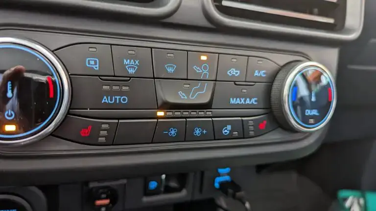
(Image credit: mavericktruckclub.com)
How Serious Is The P1464 Ford Code?
The P1464 DTC code’s severity is generally low, and it typically doesn’t impact immediate driveability or safety in Ford vehicles. While it relates to the AC system‘s self-test process, it doesn’t affect critical vehicle functions.
So can you are able to continue to drive with this code? The answer is YES. However, addressing the issue promptly is advised to prevent potential long-term AC problems and maintain optimal comfort.
What Are The Symptoms Of P1464 Code On Your Ford?
Identifying the P1464 code’s presence can be crucial in addressing potential AC system issues. Here are the key symptoms associated with this DTC:
- Check engine light illuminated
- Bad AC performance
Read more: Complete List Of Ford OBD2 Codes for FREE Download
What Are The P1464 Ford Code’s Potential Causes?
Let’s explore the common causes behind this P1464 Ford code:
- A/C or defrost on during self-test
- A/CCS circuit short to voltage
- Faulty A/C demand switch
- Damaged Wide Open Throttle A/C Cutoff (WAC) relay
Note: If the A/C or defrost functions were active during the self-test, it’s recommended to deactivate them and then repeat the self-test process.
How To Diagnose And Fix The P1464 Ford Code?
In this section, I will guide you through the process of addressing the issue, along with detailing the necessary tools and parts required for the task.
Essential Tools And Parts
To address the P1464 DTC code in your Ford vehicle’s AC system, you might need the following tools and parts:
Fixing Nissan P1464: Step-by-step Procedure
Resolving the P1464 DTC code in your Ford vehicle involves a systematic approach to identifying and addressing the underlying issue. Here’s a step-by-step guide on how to fix this code:
Step 1: Turn off A/C and defrost
If the air conditioning (A/C) or defrost functions were active during the self-test when the code was triggered, start by turning them off.
Step 2: Rerun the self-test
After disabling the A/C and defrost, rerun the self-test procedure. This can sometimes reset the system and clear the code if it was triggered due to temporary conditions.
Step 3: Inspect wiring and connectors
Inspect the wiring and connectors associated with both the A/C demand switch and the A/C control module, searching for indications of damage, corrosion, or connections that have become loose.
Step 4: Test the A/C demand switch
Using specialized equipment, test the A/C demand switch’s readings to ensure they are within the expected range. Replace the sensor if it’s providing inaccurate readings.
Step 5: Check WAC Relay Harness
Examine the wiring harness of the WAC relay for any signs of damage. Repair or replace the harness as needed.
Step 6: Clear the Code
After making necessary repairs, use an OBD-II scanner to clear the P1464 code from the vehicle’s memory. This step will also reset the check engine light.
Step 7: Test Drive
Take your vehicle for a test drive to ensure the code doesn’t reappear and that the A/C system is operating smoothly.
Read more: P1131 Ford: Symptoms, Causes, and How to Fix
Estimated Cost For Fixing P1464 On Ford Vehicles
If you’re not confident in your DIY skills or if the tasks involved seem challenging, it’s important to consider seeking the expertise of a professional mechanic. Complex automotive systems require precision and experience to diagnose and fix effectively. Attempting tasks beyond your comfort level could lead to further issues or safety concerns. Your safety and the optimal functioning of your vehicle are paramount, so if in doubt, don’t hesitate to consult a skilled professional who can handle the task with confidence.
Here’s a general breakdown of estimated costs for the outlined repairs. Please note that these figures are rough estimates and the actual expenses may fluctuate based on a range of factors.
| Repair Task | Estimated Cost |
| Wiring and Connectors Repair | $50 to $100 |
| A/C Demand Switch Replacement | $20 to $100 |
| Throttle A/C Cutoff Relay Fixing | $10 to $50 |
P1464 Ford Infographic
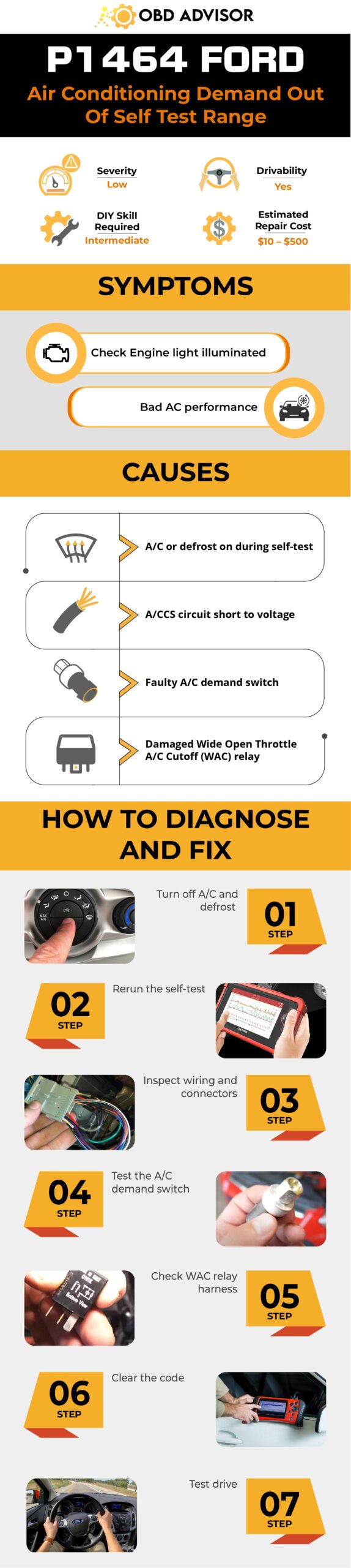
Conclusion
With the insights provided in this article, tackling the P1464 DTC in your Ford vehicle’s AC system becomes more manageable. Though the severity is typically low, taking action promptly is advised to prevent potential future issues. Whether you’re a confident DIYer or prefer professional assistance, the outlined steps offer a path to restoring your AC system’s optimal function.
If you found this article useful, consider sharing it with others who might benefit. Feel free to leave your comments below; your experiences and feedback are valuable. Together, we can ensure comfortable and hassle-free journeys in our Ford vehicles.
Reference Sources
- 2005 Ford Pickup F150 P1464 – PRODEMAND
- HOW DO AIR CONDITIONING SYSTEMS WORK IN A CAR? – Universal Technical Institute
P1701 Nissan Code: Get It Fixed With Ease Like Never Before
P1701 Nissan Code: Get It Fixed With Ease Like Never Before
Hey there! Stumbled upon the P1701 Nissan code, huh? If you find yourself scratching your head trying to decipher its meaning, you’re in the right place.
In this comprehensive guide, we’ll dig deep into the meaning of the P1701 Nissan code, its severity, causes, and the telltale symptoms to watch out for.
But that’s not all – I’ll also provide you with expert tips on diagnosing the issue and fixing it easily.
So, grab your toolbox, and let’s get started!
P1701 Nissan: A Quick Overview
Below is a summary of the P1701 Nissan Code. Check it out!
- Definition: Transmission Control Module (Power Supply)
- Severity: Medium
- DIY Skill Level: Intermediate
- Continue To Drive?: Yes
- Estimated Repair Cost: $75-$200
What Does The P1701 Code Mean On Nissan?
According to the manufacturer’s manual, the P1701 Nissan code is often triggered when the power supply to the transmission control module (TCM) is deliberately shut off. In simpler terms, this code is like a secret message from your vehicle, telling you there’s a hiccup in the power supply to the TCM.
Think of the TCM as the brain of your transmission system, responsible for things like gear shifting and controlling solenoids. Here’s the deal: The TCM relies on a steady and reliable power supply to work its magic.
But sometimes, things go awry. The P1701 code pops up when there’s an interruption or disconnection in the power supply to the TCM. This can happen when you mess with the battery, remove it, or if there’s a pesky wiring issue in the TCM circuit.
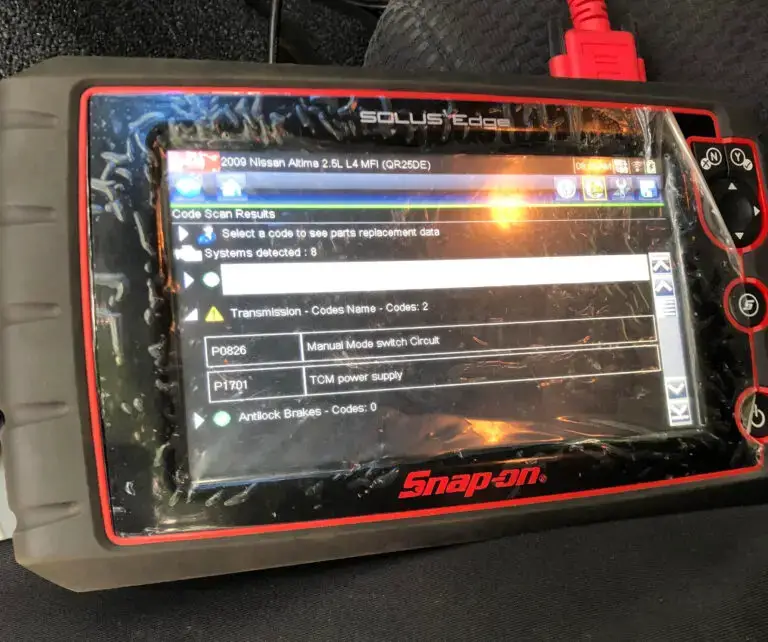
Note: Friendly reminder! Sometimes, the P1701 code doesn’t indicate a real problem. When you intentionally cut off the power supply to the TCM, this message might appear on the screen.
To tell the difference between intentional power interruptions and actual malfunctions, consider the situation in which the code appears. If it shows up without you intentionally cutting off the power supply, it’s likely pointing to a genuine malfunction that needs your attention.
Additionally, it’s worth noting that the P1701 code most commonly appears in the following Nissan models: Altima, Maxima, Murano (2005, 2007), Rogue (2008, 2009, 2011, 2013), Sentra, Altima (2008, 2009, 2011, 2012), Nissan Juke, Sentra (2008, 2010, 2011, 2012), and X-Trail. This code is frequently associated with the P0826 code.
The Severity Of P1701: Is Your Nissan In Danger?
The severity level of the P1701 code can be considered medium. While it doesn’t indicate an immediate danger to your Nissan, it shouldn’t be ignored.
You can continue to drive with the code present, but it is recommended for the short term only. It’s important to address the issue as soon as possible to prevent potential transmission problems.
Listen To Your Car: Recognizing Symptoms Of P1701
Common symptoms associated with the P1701 Nissan code include:
- Illuminated check engine light (CEL) or service engine soon (SES) warning light
- Battery light on
- Transmission-related issues, such as rough shifting, slipping, or hesitation
Read more: 4 Most common transmission control module symptoms
Solving The Puzzle: Common Causes Of P1701 Nissan Code
Based on my experience dealing with Nissan vehicles, the P1701 code is often caused by harness or connector issues.
Picture this: open or shorted circuits in the battery or ignition switch or a glitch in the TCM circuit. Those pesky wires! Sometimes they get damaged—frayed or broken, you know. And loose or corroded connectors? They can mess with the electrical connections, triggering the P1701 code.
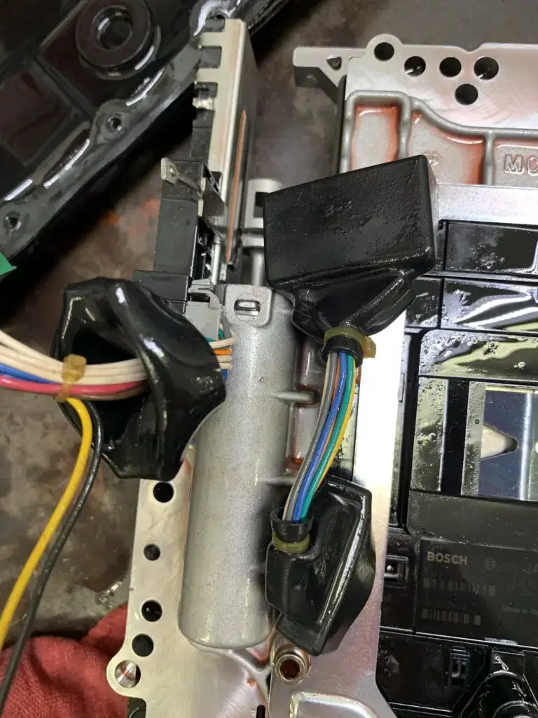
(Image credit: JustAnswer)
In rare cases, I’ve also seen instances where the TCM itself can go wrong, leading to this code. However, harness and connector issues tend to be more common culprits.
Read more: 6 Easy Ways To Find What Transmission You Have [with Transmission Lookup Tool]
Fixing P1701: Step-by-Step Repair And Diagnosis
Now that we’ve uncovered the common causes behind the P1701 Nissan code, it’s time to roll up our sleeves and dive into the world of repairs.
An effective way to tackle the P1701 code is by examining the harnesses and connectors associated with the battery, ignition switch, and TCM. Look for damage, loose connections, or corrosion.
Let’s dive into the nitty-gritty details with our step-by-step procedure below.
Essential Tools And Parts
- Wire connectors
- Nissan ignition switch
- Multimeter
- Inspection mirror
- Electrical tape
- Pullers
- Screwdriver
- Electrical cleaner
Step-by-step Procedure
Step 1: Use a multimeter to verify the TCM power source. Check the voltage at specific terminals of the TCM harness connector.
Step 2: Inspect the TCM ground circuit. Check the continuity between specific terminals of the TCM harness connector and ground.
Step 3: Confirm the TCM power circuit by measuring the voltage at specific terminals of the TCM harness connector.
Step 4: Examine the harnesses between the TCM and IPDM E/R, as well as between the TCM and the battery, ensuring continuity between specific terminals. If any damaged or faulty components are found, repair or replace them accordingly.
Step 5: Check the continuity between specific terminals of the TCM harness connector and ground. Then, inspect and replace faulty components, such as fuses or the ignition switch, as needed.
Step 6: Detect malfunctioning items by inspecting the TCM connector pin terminals for damage or loose connections with the harness connector. Repair or replace any faulty or damaged components/parts found during this inspection.
Please note that specific Nissan models may have additional information or variations related to this code. To ensure accuracy, refer to your vehicle’s service manual and consult relevant Technical Service Bulletins (TSBs). Those documents might have specific directions on checking fuses, battery voltage, terminal locations, and other relevant details.
DIY Repair Level And Estimated Costs For Fixing P1701 Code In Nissan Vehicles
The above procedure requires an intermediate level of automotive repair knowledge and experience. It involves performing various electrical tests, checking harnesses, and potentially replacing damaged components. If you have experience in automotive diagnostics and repair, you can confidently tackle this repair.
However, if you are unsure or lack experience, seeking professional assistance’s always a good idea. This approach can help you avoid unnecessary expenses resulting from inaccurate diagnoses or improper repairs.
To give you a general idea of the estimated repair costs for the P1701 code in Nissan vehicles, here’s a breakdown of the main repair tasks and their associated costs:
| Repair Task | Estimated Cost Range |
| Diagnostic Fee | $80 – $150 |
| Wiring Harness Repair/Replacement | $200 – $500 |
| Fuse Replacement | $10 – $50 |
| Ignition Switch Replacement | $100 – $300 |
| TCM Replacement | $400 – $700 |
| Professional Labor (per hour) | $80 – $150 |
Please keep in mind that these are rough estimates, and the actual costs can vary depending on factors such as your specific Nissan model, labor rates in your area, and the extent of the repair required.
It’s always recommended to consult with local repair shops or dealerships to get more accurate and tailored cost estimates for your specific situation.
P1701 Nissan Infographic
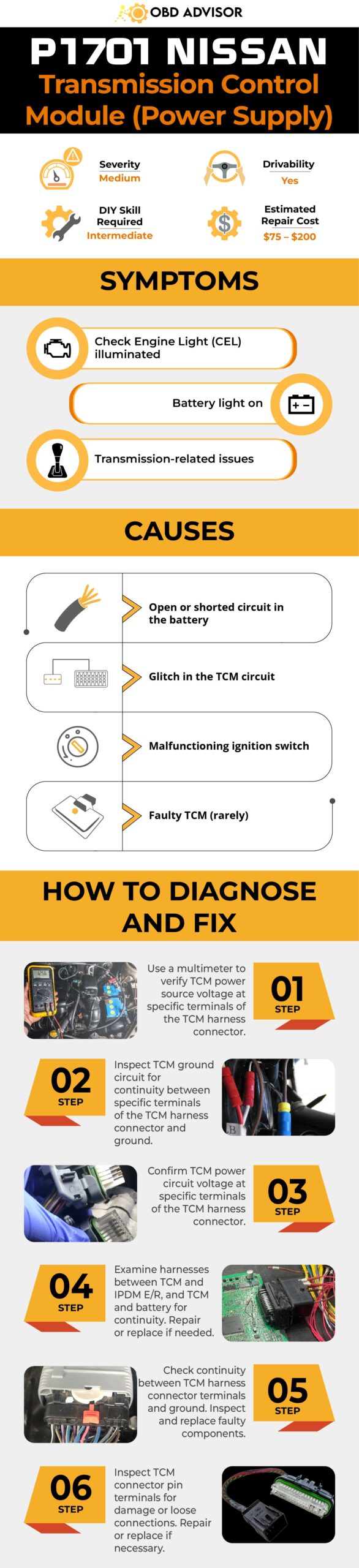
Final Thoughts
In a nutshell, promptly addressing the P1701 Nissan code is crucial to avoid potential transmission troubles.
Get to grips with its meaning, symptoms, and causes to make savvy decisions about the repairs needed. Remember to arm yourself with the right tools, follow the steps carefully, and don’t hesitate to seek pro help if required.
Never underestimate the importance of nipping that P1701 code in the bud to keep your Nissan purring like a well-oiled machine.
Got any questions or tales to share?
Drop a comment or pass on this article to fellow gearheads who might find it handy.
Let’s keep the conversation rolling and lend a hand on our automotive adventures!
Reference Sources
- Nialtima, P1701 Transmission Control Module (Power Supply)
- JustAnswer, Code P1701: No Symptoms or Transmission Issues
- 2CarPros, Transmission Codes
P1715 Nissan Code Solved: Tips For Dealing With Transmission Issues
P1715 Nissan Code Solved: Tips For Dealing With Transmission Issues
Welcome, fellow Nissan owners and avid mechanics!
Today, we’re here to uncover the secrets of a common trouble code that might have left you scratching your head: P1715 Nissan.
If you’ve encountered this code during a scan or noticed unusual behavior in your Nissan vehicle, fear not!
In this blog post, we’ll explore P1715: its meaning, severity, symptoms, causes, as well as diagnosis and repair process. Gain a clear understanding of this code and learn how to address it in your Nissan vehicle.
Let’s dive in!
P1715 Nissan: A Quick Overview
Here’s a quick overview of the P1715 code for Nissan. Check it out!
- Definition: Input Speed Sensor (Primary Speed Sensor/TCM Output)
- Severity: Medium
- DIY Skill Level: Advanced
- Continue To Drive?: Yes (at a safe speed)
- Estimated Repair Cost: $100 – $500
Understanding The P1715 Code In Nissan Vehicles
The P1715 code is a diagnostic trouble code commonly encountered in Nissan vehicles. It relates to issues of the input speed sensor and its circuit, which are crucial components of the transmission system. Let’s explore what this code means and how it can be triggered.
In Nissan vehicles, the input speed sensor monitors how fast the transmission’s input shaft rotates. It provides essential information to the transmission control module (TCM) about the transmission’s input speed. This data helps the TCM make decisions regarding gear shifting, torque converter lock-up, and overall transmission performance.
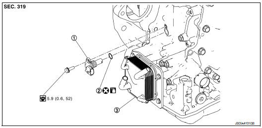
(Credit: nirogue.com)
When the input speed sensor circuit malfunctions or fails to provide accurate data, it triggers the P1715 code. It’s worth noting that the P1715 code is commonly found in Nissan models including the Nissan Rogue, Sentra, Altima, Murano, Pathfinder, and Versa.
Additionally, the P1715 code is often associated with other codes like P1778, which indicates critical CVT failure, and P0776, which relates to pressure control solenoid performance. It’s important to address the P1715 code promptly to prevent further damage to the transmission system.
Oh No! How Serious Is The P1715 Code?
The P1715 code has a moderate severity level. While it’s not considered a critical issue that requires immediate action, it shouldn’t be ignored either. Driving with the P1715 code present may lead to irregular shifting, decreased fuel efficiency, and potential transmission issues.
Always prioritize safety and drive at a safe speed. It’s highly recommended to address the code as soon as possible to prevent further damage to the transmission system.
Even though you can still drive with the code, you should have a qualified mechanic inspect your vehicle at your earliest convenience. They will diagnose the underlying cause and perform the necessary repairs to ensure your car continues to perform well and stays reliable for the long haul.
Remember, timely attention to the P1715 code can help avoid more severe transmission problems down the road.
Read more: P1701 Nissan Code: Transmission Control Module (Power Supply)
Common Symptoms Of The P1715 Code
When the P1715 code is triggered in a Nissan vehicle, it can manifest through various symptoms, including:
- Illuminated Check Engine Light
- Irregular shifting or hesitation during gear changes
- Harsh or delayed engagement when shifting gears
- Decreased fuel efficiency
- Transmission slipping or jerking
If the P1715 code is accompanied by the P0776 code, you may also experience the following:
- Hesitation and/or reduced power
If the P1715 code is together with the P1778 code, you may observe the following:
- Check Engine Light, AWD light, and ABS light all coming on
- Codes being triggered only when the transmission is cold and disappearing when warm
Causes Of The P1715 Code In Nissan Vehicles
The P1715 code in Nissan vehicles can be caused by several factors, such as:
- Open or shorted CAN communication line
- Open or shorted input speed sensor circuit
- Faulty input speed sensor
- TCM malfunction
Let’s Get Technical: Diagnose & Resolve P1715 Nissan Code
When dealing with the P1715 code in Nissan vehicles, the main solution typically involves the following steps:
Diagnostic Tools And Essential Parts
- OBD-II scanner
- Mechanical CVT repair tools
- Replacement input speed sensor (if necessary)
- TCM reprogramming or replacement tools (if necessary)
Step-by-Step Guide To Repairing The P1715 Nissan Code
- Use an OBD-II scanner or code reader to retrieve and note any additional codes present in the system.
- Inspect the wiring and connectors related to the input speed sensor circuit for any damage, loose connections, or corrosion.
- Test the input speed sensor using a multimeter to ensure it is functioning properly.
- If the sensor is faulty, replace it with a new one, ensuring proper alignment and positioning.
- Perform mechanical CVT repair if needed, addressing any internal issues or failures. This may involve:
- Replacing the CVT belt or chain if worn or damaged
- Repairing or replacing pulleys or cones if they are faulty
- Repairing or replacing the valve body if it is damaged
- Replacing faulty bearings within the CVT
- If the P1715 code persists, consider reprogramming or replacing the TCM to ensure proper communication and functionality.
Notes: It is crucial to follow manufacturer guidelines and consult service manuals for specific procedures and specifications during CVT repair and TCM replacement.
DIY Repair Level And Estimated Costs
The diagnostics and repairs for the P1715 code, particularly mechanical CVT repair, and TCM replacement, often require advanced automotive knowledge and specialized tools. You should consult with an experienced mechanic or authorized dealership for these repairs.
Costs for repairing the P1715 Nissan code can vary significantly depending on the extent of the issue, the specific vehicle model, and labor rates. It is advisable to consult with a professional for an accurate cost estimate. Below is a breakdown:
| Repair Task | Estimated Cost Range |
| Wiring and Connectors Repair/Replacement | $100 – $500 |
| Input Speed Sensor Replacement | $100 – $300 |
| Mechanical CVT Repair | $500 – $1500 |
| TCM Reprogramming | $100 – $300 |
| TCM Replacement | $300 – $800 |
P1715 Nissan Infographic
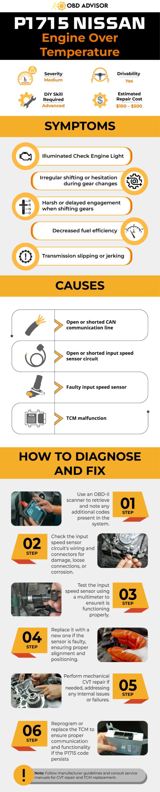
Final Thoughts
In a nutshell, fixing the P1715 Nissan code requires a careful approach and targeted repairs. But don’t worry! You don’t have to face it alone.
Reach out to a skilled mechanic or authorized dealership who can guide you through the process with expertise and a friendly smile.
If you found this information helpful, why not spread the love?
Share it with your friends and family who might be dealing with the same issue.
And hey, we’re all ears for your thoughts and experiences too! Drop us a comment below, and let’s keep the conversation rolling.
Reference Sources
- Nissan North America, 2018, Technical Service Bulletin AT18-009.
- Nissan Rogue, Service Manual: P1715 input speed sensor.
- Nissan Sentra, Service Manual: P1715 input speed sensor.
- Nissan Altima, Service Manual: P1715 input speed sensor.
- JustAnswer, Code P1715 Question – Answered by Nissan Mechanic Ron.
P25A2 Code: Expert Explanation And Recommendations
P25A2 Code: Expert Explanation And Recommendations
Have you seen the Malfunction Indicator Light (MIL) illuminated with code P25A2? This possibly indicates a problem with the Brake System Control Module (BSCM) or the brake system.
These are essential parts of your car, and a problem with them can be dangerous. Therefore, it is crucial to understand what the code P25A2 means and what you should do if you see it.
In this article, I’ll explain what the code means, discuss the possible causes, and share my advice on what you should do.
So, read on to learn more!
P25A2 Code: An Overview
The P25A2 code can be a bit confusing, but here’s a breakdown of it:
- Definition: Brake System Control Module Requested MIL Illumination
- Severity: Medium
- DIY Skill Level: Advanced
- Continue To Drive?: Yes
- Estimated Repair Cost: $50 – $200
What Does The P25A2 Code Mean?
The P25A2 code is a generic diagnostic trouble code (DTC) defined as “Brake System Control Module Requested MIL Illumination.” This code is not specific to any particular vehicle make or model, but it is commonly triggered in GM vehicles such as the Chevy Silverado, Volt, Corvette, and GMC Sierra.
This DTC suggests that there is a fault or malfunction detected within the brake system control module, which has triggered the module to request the illumination of the MIL. The brake system control module monitors and controls various aspects of the vehicle’s braking system, including ABS (Anti-lock Braking System) and traction control.
When a fault or malfunction is detected within the brake system, such as a sensor reading out of range or a valve not functioning as expected, the brake system control module may set the P25A2 code and request the illumination of the MIL.
The P25A2 code is often associated with other codes which further clarify the issue, such as:
- P0606: PCM / ECM Processor Fault
- C0021: Brake Booster Performance (Subfault)
- C05D2: Brake Master Cylinder Piston Excessive Travel Detected
- U0139: Lost Communication with Suspension Control Module “B”
How Serious Is The P25A2 Code?
When it comes to the severity level of the P25A2 code, it is generally considered medium. In general, the code doesn’t necessarily pose an immediate danger to your vehicle or a complete failure of the braking system.
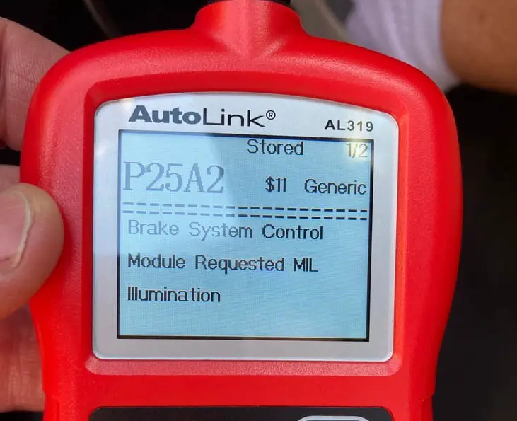
(Image credit: Corvette Forum)
Despite the code being present, it is generally safe to continue driving. However, to ensure the continued safe operation of your vehicle, having your car inspected and diagnosed by a qualified mechanic at your earliest convenience is recommended.
Read more: GM OBD2 Codes List For FREE Download [Generic + Manufacturer-specific]
Warning Signs Of The P25A2 Code
The P25A2 code may manifest through various symptoms, including:
- Illumination of the check engine light and/or ABS warning light
- Brake system performance issues
Possible Causes Of The P25A2 Code
The code P25A2 can be triggered by several potential causes, such as:
- Malfunctioning brake pedal position sensor
- Faulty wheel speed sensors
- Problem with the brake system wiring
- Wiring or connection issues within the BSCM
- BSCM’s software glitch
- Faulty BSCM
Read more: C0035 Code: Understanding Wheel Speed Sensor Issues
What to Do If You See The P25A2 Code?
As a mechanic, I strongly recommend that you seek professional help if you encounter the P25A2 code. Additionally, it is important to refrain from attempting to fix the code yourself, as it can be a complex situation, particularly for a DIY-er.
There are a few reasons why it is important to take your car to a qualified mechanic or ask for help from your nearest car dealer:
- The P25A2 code often appears associated with other codes, making it difficult to diagnose and fix on your own.
- There are many technical service bulletins (TSBs) related to this code, which your car may be covered by. For example, in 2020, GM had a TSB called PIT5735D to address the P25A2 code associated with U0422, U0420, U0151, and other complex U-codes. A mechanic can apply the TSB and recommend the best action to fix your car.
- The BSCM is a critical safety component, and it is important to have it repaired by a qualified mechanic with the proper tools and knowledge.
Additionally, some of the repairs that may be needed to fix the P25A2 code include:
- Updating the software
- Repair wiring issues
- Repairing or replacing a faulty braking-related components (wheel speed sensor, brake actuator, brake line, etc)
- Replace the BSCM
Final Thoughts
To wrap up, understanding the P25A2 code and its impact on your vehicle’s brake system is crucial for maintaining safety on the road. While it is a medium severity code, we recommend seeking professional assistance by taking your car to an authorized dealer or qualified mechanic. They have the expertise and resources to diagnose and address the issue.
We hope this article has helped you understand the P25A2 code. If you found this information helpful, please share it with others who may benefit. Feel free to leave a comment below to share your experiences or ask any questions.
Happy driving!
Reference Sources
How a Car Works, How the braking system works.
P051B Code: A Comprehensive Guide for Vehicle Owners
P051B Code: A Comprehensive Guide for Vehicle Owners
Welcome, vehicle owners! If you’ve encountered your vehicle’s P051B error code, you’ve arrived at the right place.
In this guide, we’ll explore the details of the P051B code, its meaning, severity, symptoms, causes, and the necessary diagnosis and repair steps. As experienced mechanics with a wealth of knowledge, we’re here to share our expertise and assist you in resolving this issue.
So, let’s dive in!
P051B Code: Quick Overview
Here is an overview of the P051B code. Take a look!
Definition: Crankcase Pressure Sensor Circuit Range/Performance
Severity: High
DIY Skill Level: Intermediate
Continue To Drive?: No
Estimated Repair Cost: $100 – $300
What Does The P051B Mean?
The P051B error code indicates a problem with the Crankcase Pressure Sensor Circuit Range/Performance. This code is commonly found in various car brands, including Ford equipped with EcoBoost engines, Dodge with Cummin engines, etc.
The Crankcase Pressure Sensor is an essential part of the vehicle’s emission control system. It works with the Positive Crankcase Ventilation (PCV) system, which manages the pressure and circulation of gases within the engine crankcase.Under normal operating conditions, the Crankcase Pressure Sensor monitors the pressure levels within the crankcase. If the sensor detects that the pressure deviates from the expected range, it sends a signal to the engine control module (ECM) or powertrain control module (PCM), triggering the P051B error code.
It’s worth noting that the P051B code is often associated with code P04DB, which indicates a problem with the Crankcase Ventilation System Disconnected. These codes are closely related, as a malfunction in the crankcase ventilation system can impact the sensor’s readings, leading to the P051B code being triggered.
Is it Safe to Continue Driving With The P051B?
The P051B code is considered to be of high severity level. Ignoring or continuing to drive with the P051B code can have severe consequences, including engine performance degradation, reduced fuel efficiency, and the risk of further damage to crucial engine components.
It is crucial to address this code promptly to prevent further complications and ensure your vehicle’s safe and optimal operation. We strongly advise against driving with the P051B code present and diagnosis and repair as soon as possible.
Signs of The P051B Code
The following are common symptoms associated with the P051B error code:
- Illuminated Malfunction Indicator Lamp (MIL) or Check Engine Light
- Reduced engine performance or power
- Engine misfires or rough idle
- Decreased fuel efficiency
What Triggers the P051B Code?
The P051B error code can be caused by various factors, including:
- Engine over-filled with oil
- Faulty or malfunctioning crankcase pressure sensor
- Dirty/bad positive crankcase ventilation valve
- Water intrusion in crankcase pressure sensor
- Issues with the wiring or connectors related to the sensor
- Crankcase ventilation system problems: broken hoses, blown valve cover gasket, failed oil fill cap, v.v
- PCM or ECM software or programming issues
How To Diagnose And Fix The P051B Code
In this section, we will provide you with the necessary tools and parts required for diagnosing and repairing the P051B error code. We will then guide you through a step-by-step procedure to address the issue effectively.
Essential Tools and Parts
- OBD-II scanner or code reader
- Basic hand tools (such as wrenches, sockets, and screwdrivers)
- Crankcase pressure sensor (if necessary)
- Positive crankcase ventilation valve
- Vacuum hose/connector
- Electrical connectors and wiring repair kit
Step-by-Step Procedure
- Retrieve Diagnostic Trouble Codes:
Connect an OBD-II scanner or code reader to retrieve the trouble codes and identify the P051B code.
- Check the engine oil:
Use the dipstick to check the engine oil. Make sure it’s not overfilled. Drain the excess oil if needed.
- Visual inspection of the Positive Crankcase Ventilation (PCV) System:
- Inspect the PCV valve, hoses, and connections for any signs of leaks, damage, or restrictions. Ensure that the PCV valve maintenance schedule has been followed.
- Verify that the correct PCV valve part number is being used.
- Check the cleanliness and correct routing of the fresh air tube and related hoses.
- If any concerns are found during the inspection, repair or replace the affected components.
- Check for Leaks:
- Inspect the oil cap, throttle body, PCV hose, vacuum lines and the air intake system for any leaks or damages.
- Repair or replace the faulty parts if needed.
- Inspect the wiring and connectors related to the crankcase pressure sensor:
- Inspect the wiring and connectors related to the crankcase pressure sensor for any visible damage, loose connections, or corrosion.
- If wiring issues are found, repair or replace the damaged wiring and ensure proper connections.
- Test the Crankcase Pressure Sensor:
- Use a multimeter to test the crankcase pressure sensor. Ensure to consult the manufacturer’s specifications for testing procedures.
- If the reading is out of range, replace it with a new one and make sure proper installation.
- Clear code and test drive:
Clear the error codes using the OBD-II scanner and test the vehicle to verify if the P051B code reoccurs.
Note: It is recommended to consult the vehicle’s service manual or seek professional guidance for specific instructions and testing procedures tailored to your vehicle’s make and model.
DIY Repair Level And Estimated Costs
The level of DIYer skill required to address the P051B error code can vary from immediate to advanced. It is important to consider your mechanical skills and experience when deciding whether to tackle the diagnosis and repair yourself.
While some individuals may feel confident in performing the diagnosis and repair themselves, others may prefer to seek assistance from a professional mechanic. It is important to assess your capabilities and comfort level before proceeding with DIY repairs.
Below is a table of estimated costs for repairing the P051B error code:
| Repair Task | Estimated Cost Range |
| Crankcase Pressure Sensor Replacement | $50 – $200 |
| Wiring Repair | $50 – $200 |
| Vacuum Leak Repair | $100 – $300 |
| Professional Diagnostic Fee | $75 – $150 |
Please note that these estimated costs are intended to provide a general idea and can vary depending on the vehicle make and model, location, and labor rates. It’s always recommended to consult local mechanics or obtain quotes from automotive repair shops to get a more accurate estimate tailored to your situation.
Final Thoughts
Now, you have a comprehensive understanding of the P051B error code and how to address it. By recognizing the symptoms, understanding the causes, and following the step-by-step repair procedure, you are equipped to tackle this issue confidently. Remember, it is crucial to address the P051B code promptly to prevent further complications and ensure the safe operation of your vehicle.
If you found this guide helpful, feel free to share it with other car enthusiasts who may benefit from this knowledge. We also encourage you to leave your comments or questions below. Your feedback is valuable, and we’re here to provide further assistance or clarify any doubts you may have.
Keep your vehicle running smoothly and stay informed about other car-related topics. Safe travels!
Reference:
Howstuffworks – How Does a Positive Crankcase Ventilation (PCV) System Work?